WO2017163295A1 - Réfrigérateur - Google Patents
Réfrigérateur Download PDFInfo
- Publication number
- WO2017163295A1 WO2017163295A1 PCT/JP2016/058885 JP2016058885W WO2017163295A1 WO 2017163295 A1 WO2017163295 A1 WO 2017163295A1 JP 2016058885 W JP2016058885 W JP 2016058885W WO 2017163295 A1 WO2017163295 A1 WO 2017163295A1
- Authority
- WO
- WIPO (PCT)
- Prior art keywords
- shelf
- rail
- depth direction
- refrigerator
- disposed
- Prior art date
- Legal status (The legal status is an assumption and is not a legal conclusion. Google has not performed a legal analysis and makes no representation as to the accuracy of the status listed.)
- Ceased
Links
Images






Classifications
-
- F—MECHANICAL ENGINEERING; LIGHTING; HEATING; WEAPONS; BLASTING
- F25—REFRIGERATION OR COOLING; COMBINED HEATING AND REFRIGERATION SYSTEMS; HEAT PUMP SYSTEMS; MANUFACTURE OR STORAGE OF ICE; LIQUEFACTION SOLIDIFICATION OF GASES
- F25D—REFRIGERATORS; COLD ROOMS; ICE-BOXES; COOLING OR FREEZING APPARATUS NOT OTHERWISE PROVIDED FOR
- F25D25/00—Charging, supporting, and discharging the articles to be cooled
- F25D25/02—Charging, supporting, and discharging the articles to be cooled by shelves
Definitions
- the present invention relates to a refrigerator, and more particularly, to a structure of a shelf disposed in a refrigerator storage chamber and a structure of a member that supports the shelf.
- Patent Document 1 There has been proposed a refrigerator storage room in which a shelf on which stored items are placed and a rail that supports the shelf are arranged (see, for example, Patent Document 1).
- the front side portion of the shelf is disposed on the front side of the front end of the rail.
- the stored item In order to take out the stored item on the shelf, the stored item may come into contact with the shelf when the stored item is pulled out to the front side of the refrigerator.
- the stored item and the shelf may come into contact with each other.
- the shelf rotates about the position of the front end of the rail. There is. If the shelf rotates, the stored items on the shelf may move or fall over.
- the present invention has been made to solve the above-described problems, and an object thereof is to provide a refrigerator that prevents the shelves arranged in the storage chamber from rotating.
- the refrigerator according to the present invention includes a housing in which a storage chamber is formed, a plate-shaped shelf disposed in the storage chamber, a first rail portion provided in the storage chamber and supporting one side end of the shelf.
- a second rail portion provided in the storage chamber and supporting the other side end of the shelf, wherein the first rail portion is disposed on one side end of the shelf, and the depth direction of the storage chamber
- a first upper rail formed to extend to the shelf, and a first lower rail that is disposed below one side end of the shelf and is formed to extend in the depth direction, and is in contact with the lower surface of the shelf
- the second rail portion is disposed on the other side end of the shelf, and is disposed below the other side end of the shelf, the second upper rail formed to extend in the depth direction of the storage chamber, A second lower rail formed to extend in the depth direction and in contact with the lower surface of the shelf, wherein the first upper rail is disposed in the depth direction
- a first convex portion is provided opposite to the upper surface of one side end of the shelf,
- the refrigerator according to the present invention since the above configuration is provided, it is possible to prevent the shelf arranged in the storage chamber from rotating.
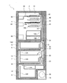
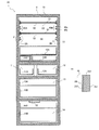
- FIG. 2 is a cross-sectional view taken along the line AA shown in FIG. It is a longitudinal cross-sectional view in the surface orthogonal to the cross section shown in FIG.
- FIG. 7A It is a figure which shows the state which opened the refrigerator compartment door 3 and the refrigerator compartment door 4 of the refrigerator 1 which concerns on embodiment of this invention to the angle of 90 degree
- FIG. 9B It is a figure which shows the various dimensions of the refrigerator 1 in the state which opened the refrigerator compartment door 3 and the refrigerator compartment door 4 to the angle of 90 degree
- FIG. It is a figure which shows the modification 2 of the refrigerator 1 which concerns on embodiment of this invention, Comprising: It is a figure of the state which mounted the shelf 250 on the rail part 240.
- FIG. It is a figure which shows the state which removed the shelf 250 shown to FIG. 12A from the rail part 240.
- FIG. 1 is a perspective view of a refrigerator 1 according to the present embodiment.
- FIG. 2 is a cross-sectional view taken along line AA shown in FIG. 3A is a longitudinal sectional view in a plane orthogonal to the cross section shown in FIG. 2, and
- FIG. 3B is an explanatory view of the inner box 2t2 and the like.
- FIG. 1 schematically shows a part of the internal structure of the refrigerator 1 (for example, the ice making chamber 11).
- Fig.3 (a) is not the longitudinal cross-sectional view in doors of storage rooms, such as the refrigerator compartment door 3, but the longitudinal cross-sectional view in the housing
- FIG. 3B is a cross-sectional view taken along the line A1-A1 shown in FIG.
- the refrigerator 1 includes a housing 2 in which a storage room for storing stored items is formed.
- the housing 2 includes, for example, a resin inner box 2t2 and a steel outer box 2t1 positioned outside the inner box 2t2.
- a heat insulating material 2t3 is disposed between the inner box 2t2 and the outer box 2t1.
- the heat insulating material 2t3 either one of foamed urethane or the like, a vacuum heat insulating material, or both may be used.
- a refrigerator compartment 10 an ice making compartment 11, a switching compartment 12, a freezer compartment 13, and a vegetable compartment 14 are formed.
- one or more of the refrigerating room 10, the ice making room 11, the switching room 12, the freezing room 13, and the vegetable room 14 may be referred to as a storage room for convenience.
- the housing 2 is provided with a first rail portion 40A described later, and includes a first surface 2A that partitions the storage chamber (refrigeration chamber 10) side and the heat insulating material 2t3 side.
- the housing 2 is provided with a second rail portion 40B, is opposed to the first surface 2A, and is a second surface that partitions the storage chamber (refrigeration chamber 10) side and the heat insulating material 2t3 side. 2B (these are referred to as configuration A7).
- casing 2 contains the 3rd surface part 2C formed in the back of the storage room (refrigeration room 10).
- the refrigerator 1 does not necessarily have the configuration A7.
- the first rail portion 40A and the second rail portion 40B may be provided on the side wall surfaces in the refrigerator compartment 10 other than the first surface 2A and the second surface 2B.
- the rail part 40 and the 1st surface 2A and the 2nd surface 2B may be comprised integrally as demonstrated in this Embodiment, and a different body may be sufficient as it.
- the refrigerator compartment door 3 and the refrigerator compartment door 4 are arranged in front of the refrigerator compartment 10, the ice making compartment door 5 is arranged in front of the ice making compartment 11, and the switching compartment door 6 is arranged in front of the switching compartment 12.
- a freezer compartment door 7 is arranged in front of the freezer compartment 13, and a vegetable compartment door 8 is arranged in front of the vegetable compartment 14.
- a refrigerator compartment duct 30, a switching compartment duct 31, and a vegetable compartment duct 32 are formed in the housing 2.
- the refrigerator compartment door 3 and the refrigerator compartment door 4 are rotary doors.
- An operation panel 9 is provided on the outer surface of the refrigerator compartment door 3.
- the ice making room door 5, the switching room door 6, the freezing room door 7, and the vegetable room door 8 are drawer type doors.
- this drawer-type door for example, a structure in which a frame fixed to the door is slid on rails formed horizontally on the left and right inner wall surfaces of the storage chamber can be employed. Thereby, a drawer-type door can be moved to the front-back direction (depth direction), and a storage chamber can be opened and closed.
- a shelf 50 on which stored items are placed and a rail portion 40 that supports the shelf 50 are arranged.
- the shelf 50 is a flat member.
- the shelf 50 is supported in the casing 2 by the rail portion 40 in parallel to the horizontal plane.
- the rail portion 40 includes a first rail portion 40A that supports one side end of the shelf 50 and a second rail portion 40B that supports the other side end of the shelf 50. That is, the rail part 40 is provided with the 1st rail part 40A and the 2nd rail part 40B which make a pair.
- two shelves 50 are provided in the refrigerator 1. That is, the shelf 50 is provided in the rail part 40 arrange
- the shelf 50 and the rail part 40 are arranged in multiple numbers, it is not limited to it, One may be sufficient. Further, the shelf 50 may be provided on all of the plurality of rail portions 40 or may be provided on one of the plurality of rail portions 40.
- the refrigerator compartment 10 is provided with a plurality of door pockets 60 on which stored items are placed in a state where the refrigerator compartment door 3 and the refrigerator compartment door 4 are closed.
- the door pocket 60 is attached to the refrigerator compartment door 3 and the refrigerator compartment door 4.
- a sliding type case 10A and a sliding type case 10B arranged under the case 10A are arranged.
- the refrigerator compartment 10 is provided with an ice-making water tank 10C in which water used for generating ice is stored.
- a case 10B is disposed on the side of the ice making water tank 10C, and a case 10A is disposed on the case 10B.
- An ice making device (not shown) that generates ice is disposed in the ice making chamber 11.
- the ice making chamber 11 is provided with an ice making case 11A for storing the generated ice.
- a switching chamber case 12 ⁇ / b> A for placing stored items is arranged in the switching chamber 12.
- the switching chamber 12 has various refrigeration temperature zones (for example, about ⁇ 18 ° C.), refrigeration temperature zones (for example, about 3 ° C.), chilled temperature zones (for example, about 0 ° C.), soft freezing temperature zones (for example, about ⁇ 7 ° C.), etc.
- the cold insulation temperature zone can be switched to the temperature zone.
- a freezer compartment case 13A for placing stored items and a freezer compartment case 13B arranged under the freezer compartment case 13A are arranged. Furthermore, in the vegetable compartment 14, a vegetable compartment case 14A and a vegetable compartment case 14B on which stored items are placed are arranged.
- the casing 2 of the refrigerator 1 is equipped with a compressor 20 that compresses the refrigerant and a heat exchanger 21 that functions as an evaporator.
- the compressor 20 is provided in a machine room 15 that is a space formed at the bottom of the housing 2.
- the heat exchanger 21 is a cooler in the refrigerator 1 and is disposed above the compressor 20.
- coolant which function as a heat radiator in the refrigerator 1 is mounted, for example.
- the refrigerator 1 is equipped with the refrigerating cycle comprised by connecting the compressor 20, the heat radiating pipe, the pressure reduction mechanism, and the heat exchanger 21.
- the decompression mechanism for example, a capillary tube or the like can be employed.
- the casing 2 of the refrigerator 1 is equipped with a cooling fan 22 that supplies air (cold air) cooled by the heat exchanger 21 to each room such as the refrigerator compartment 10.
- the cooling fan 22 is disposed on the heat exchanger 21.
- the cold air blown from the cooling fan 22 is supplied to the refrigerating room 10, the ice making room 11, the switching room 12, and the freezing room 13 through the refrigerating room duct 30 and the switching room duct 31.
- the vegetable compartment 14 is supplied through a return air passage (not shown) through which the cold air in the refrigerator compartment 10 passes. Then, the cold air in the vegetable compartment 14 is returned to the heat exchanger 21 via the vegetable compartment duct 32.
- a temperature detection sensor that detects the temperature of the storage room, the number of rotations of the cooling fan 22, the damper for the cold room based on the temperature detected by the temperature detection sensor 24 and a control device that controls opening and closing of the switching chamber damper 23 are mounted.
- the temperature detection sensor can be composed of, for example, a thermistor.
- the control device also performs operation, stop, rotation speed control, and the like of the compressor 20, and includes, for example, a control board on which a microcomputer is mounted.
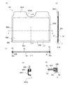
- FIG. 4 is an explanatory diagram of the shelf 50 of the refrigerator 1 according to the present embodiment.
- FIG. 4A is a top view of the shelf 50.
- FIG. 4B is a CC cross-sectional view shown in FIG.
- FIG. 4C is a DD cross-sectional view shown in FIG.
- FIG. 4D is an enlarged view of the region E shown in FIG.
- the shelf 50 is a plate-like member arranged in the storage chamber.
- the case where the shelf 50 is arranged in the refrigerator compartment 10 is shown as an example, and therefore the storage compartment corresponds to the refrigerator compartment 10.
- the shelf 50 is roughly divided into four ends. That is, the shelf 50 includes a front end 50t1, one side end 50t2, the other side end 50t3, and a rear end 50t4.
- the front end 50t1 and the rear end 50t4 intersect the side end 50t2 and the side end 50t3.
- the shelf 50 includes a shelf body 50A made of plate-like glass and a resin portion 50B made of resin, and the resin portion 50B is provided with a stopper 50c (hereinafter referred to as configuration A1). ).
- the resin part 50B is provided so as to cover the peripheral edge of the shelf body 50A.
- the resin portion 50B is provided at one side end, the other side end, the front end, and the rear end of the shelf body 50A.
- One side end, the other side end, the front end, and the rear end of the shelf main body 50A correspond to the one side end 50t2, the other side end 50t3, the front end 50t1, and the rear end 50t4 of the shelf 50.
- the resin portion 50B is in contact with the upper surface S4 of the first lower rail 40b1 and the upper surface S4 of the second lower rail 40b2 in a state where the resin portion 50B is arranged on the first rail portion 40A and the second rail portion 40B. Since the rail portion 40 has a structure including a first upper rail 40a1 and a first lower rail 40b1, the rail portion 40 has a concave structure. Moreover, in this Embodiment, in order that the illumination light in the refrigerator 1 may spread easily in a storage chamber, the shelf main body 50A is comprised with glass.
- the strength of the shelf main body 50A may be greatly reduced due to the properties of glass.
- the concave structure is formed in the rail part 40.
- the resin part 50B is provided in the shelf body 50A, it is possible to prevent the user's fingers from being damaged or the housing 2 from being damaged by the end surface of the shelf body 50A.
- a stopper 50c protruding downward is formed on the lower surface S2 of the shelf 50.
- the resin portion 50B is formed with a stopper 50c protruding downward.
- the stopper 50c is formed in the part provided in one side end of the shelf main body 50A, and the other side end, respectively.
- the present invention is not limited to this.
- it may be provided on the lower surface S2 of the shelf body 50A.
- the vertical dimension of the stopper 50c is preferably about 5 mm, for example.
- the formation position of the stopper 50c is limited to the resin portion 50B, but is not limited thereto.
- the stopper 50c may be formed continuously from one side end 50t2 to the other side end 50t3. Moreover, although the stopper 50c demonstrated the aspect formed in both the one side end of the shelf main body 50A, and the other side end in this Embodiment, one side may be sufficient.
- the front end 50t1 of the shelf 50 faces the refrigerator compartment door 3, the refrigerator compartment door 4, the door pocket 60, and the like in a state where the refrigerator compartment door 3 and the refrigerator compartment door 4 are closed.
- a part of the resin portion 50B is provided at the front end 50t1.
- the front end 50t1 is formed in a straight line.
- One side end 50t2 of the shelf 50 is supported by the first rail portion 40A provided on the first surface 2A.
- the upper surface S1 of the side end 50t2 faces the lower surface S3 of the first upper rail 40a1 of the first rail portion 40A.
- the lower surface S2 of the side end 50t2 is supported in contact with the upper surface S4 of the first lower rail 40b1 of the first rail portion 40A.
- the other side end 50t3 of the shelf 50 is supported by the second rail portion 40B provided on the second surface 2B.
- the upper surface S1 of the side end 50t3 faces the lower surface S3 of the first upper rail 40a1 of the second rail portion 40B.
- the lower surface S2 of the side end 50t3 contacts and is supported by the upper surface S4 of the first lower rail 40b1 of the second rail portion 40B.
- the rear end 50t4 of the shelf 50 faces the third surface portion 2C in a state where the shelf 50 is inserted to the back of the rail portion 40.
- a recess 50t40 is formed at the center of the rear end 50t4 so as not to interfere with the refrigerator compartment duct 30.
- FIG. 5 is an explanatory diagram of the rail portion 40 of the refrigerator 1 according to the present embodiment.
- FIG. 6A is a diagram illustrating a state in which the shelf 50 is placed on the rail portion 40 of the refrigerator 1 according to the present embodiment.
- 6B is a diagram illustrating various dimensional relationships between the rail portion 40 and the shelf 50 illustrated in FIG. 6A.
- FIG. 7A is a diagram illustrating a state in which the shelf 50 is pulled up with respect to the rail portion 40 of the refrigerator 1 according to the present embodiment.
- FIG. 7B is a diagram showing various dimensional relationships between the rail portion 40 and the shelf 50 shown in FIG. 7A.
- FIG. 5A is an explanatory diagram of a main part of the refrigerator compartment 10, and is a view of the refrigerator compartment 10 as viewed from the front side.
- FIGS. 5B1 and 5B2 are explanatory views of the first rail portion 40A shown in the region G1 of FIG.
- FIG. 5B1 is a longitudinal sectional view
- FIG. 5B2 is a side view.
- FIGS. 5C1 and 5C2 are explanatory diagrams of the second rail portion 40B shown in the region G2 of FIG.
- FIG. 5C1 is a longitudinal sectional view
- FIG. 5C2 is a side view.
- the first rail portion 40A includes a pair of rails arranged vertically. That is, the first rail portion 40A is disposed on one side end 50t2 of the shelf 50, and the first upper rail 40a1 formed so as to extend in the depth direction of the refrigerator compartment 10 and one of the shelf 50 It includes a first lower rail 40b1 that is disposed under the side end 50t2 and that extends in the depth direction and contacts the lower surface S2 of the shelf 50.
- the 2nd rail part 40B is also provided with a pair of rail arrange
- the second rail portion 40B is disposed on the other side end 50t3 of the shelf 50 and is formed so as to extend in the depth direction of the refrigerator compartment 10, and the other side end of the shelf 50.
- first upper rail 40a1 and the second upper rail 40a2 are referred to as an upper rail 40a for convenience of description, and the first lower rail 40b1 and the second lower rail 40b2 are referred to as lower for convenience of description.
- first lower rail 40b1 and the second lower rail 40b2 are referred to as lower for convenience of description.
- rail 40b Sometimes referred to as rail 40b.
- the first upper rail 40a1 is disposed on the back side in the depth direction, and is provided with a first convex portion 40c1 that faces the upper surface S1 of one side end 50t2 of the shelf 50.
- the second upper rail 40a2 is disposed on the far side in the depth direction, and is provided with a second convex portion 40c2 that faces the upper surface S1 of the other side end 50t3 of the shelf 50.
- the first protrusion 40c1 and the second protrusion 40c2 may be referred to as a protrusion 40c for convenience of description.
- a stopper 50c that protrudes downward is formed on the lower surface S2 of the shelf 50, and at least one of the upper surface S4 of the first lower rail 40b1 and the upper surface S4 of the second lower rail 40b2 has a first surface.
- An insertion portion 40f is formed in front of the convex portion 40c1 and the second convex portion 40c2 in the depth direction and into which the stopper 50c is inserted.
- a first recess 40g1 is formed on the upper surface S4 of the first lower rail 40b1 so as to face the first protrusion 40c1 and to be formed under the first protrusion 40c1 and extend in the depth direction. Has been.
- a second recess 40g2 is formed on the upper surface S4 of the second lower rail 40b2 so as to face the second protrusion 40c2 and to be formed below the second protrusion 40c2 and extend in the depth direction. (These are referred to as configuration A2).
- the first recess 40g1 and the second recess 40g2 may be referred to as the recess 40g for convenience of description.
- first and second concave portions 40g1 and 40c1 and the second convex portion 40c1 and the second convex portion 40c2 and the upper surface S1 of the shelf 50 interfere with each other and the front end of the shelf 50 is not pulled up.
- 40g2 is formed. That is, since the concave portion 40g is formed, the shelf 50 can be easily attached to and detached from the rail portion 40 even if the stopper 50c is formed.
- the depth of the recess 40g is preferably about 1 mm, for example. In the present embodiment, the case where two stoppers 50c and two insertion portions 40f are formed has been described as an example. However, the present invention is not limited to this and may be one.
- the front end 40d of the first upper rail 40a1 is disposed deeper in the depth direction than the front end 40e of the first lower rail 40b1, and the front end 40d of the second upper rail 40a2 is the front end of the second lower rail 40b2. It arrange
- the front end 50t1 is less likely to contact the front end of the upper rail 40a, and the shelf 50 can be easily attached and detached.
- the front end of the first lower rail 40b1 and the front end of the second lower rail 40b2 are the front ends of the shelf 50 in a state where the shelf 50 is disposed at the innermost part of the first rail portion 40A and the second rail portion 40B. It arrange
- the refrigerator 1 employs the configuration A4 and has a structure in which the shelf 50 is easily rotated after the shelf 50 is pulled out from the lower rail 40b.
- the refrigerator 1 has the first and second convex portions 40c1 and 40c2 so that the shelf 50 does not rotate around the front end of the lower rail 40b when stored items, user's fingers, etc. come into contact with the shelf 50. Is included.
- the first convex portion 40c1 and the second convex portion 40c2 are each formed with a tapered surface TS at the front portion in the depth direction, and the tapered surface TS is inclined downward toward the back from the near side in the depth direction. (This is referred to as configuration A5).
- the formation of the tapered surface TS has the following effects. That is, when the user inserts the shelf 50 between the upper rail 40a and the lower rail 40b and moves the shelf 50 in the depth direction, the shelf 50, the first protrusion 40c1, and the second protrusion Even if the portion 40c2 comes into contact, the shelf 50 and the rail portion 40 can be prevented from being damaged.
- a plurality of rails 40 are arranged in the refrigerator 1 so as to line up in the vertical direction (this is referred to as configuration A6). Thereby, the position of the shelf 50 can be changed.
- the shelf body 50A can be manufactured by insert molding including a shelf body 50A made of glass and a resin portion 50B made of resin.
- the shelf body 50A is preferably tempered glass so as not to be damaged, and more preferably a scatter glass attached on one side or both sides.
- the resin portion 50B is desirably made of polypropylene that is excellent in resistance to foods, detergents, and organic solvents and is inexpensive, but other resins can also be employed.
- the dimension D1 has shown the distance from the front end 40d to the front end of the convex part 40c among the upper rails 40a.
- the dimension D2 indicates the distance from the front end 40d to the tapered surface TS of the convex portion 40c in the upper rail 40a.
- the dimension d1 indicates the distance from the stopper 50c to the front end of the recess 40g.
- the dimension d2 indicates the distance from the front end of the recess 40g to the rear end 50t4 of the shelf 50.
- the dimension C1 indicates the distance from the upper surface S1 of the shelf 50 to the lower surface S3 of the upper rail 40a.
- the dimension C2 indicates the distance from the lower surface S2 of the shelf 50 to the bottom surface of the recess 40g. That is, the dimension C2 corresponds to the depth of the recess 40g.
- the dimension H1 has shown the distance from the convex part 40c to the upper surface S4 of the lower rail 40b.
- the dimension h ⁇ b> 1 indicates the thickness of the shelf 50.
- the dimension h2 indicates the distance from the lower surface S2 of the shelf 50 to the bottom surface of the insertion portion 40f. That is, the dimension h2 corresponds to the depth of the insertion portion 40f.
- the rail part 40 and the shelf 50 of the refrigerator 1 have the following dimensional relationship, for example.
- the state shown in FIG. 6B can be shifted to the state shown in FIG. 7B. That is, the stopper 50c can be removed from the insertion portion 40f by pulling up the shelf 50 while preventing the shelf 50 from being lifted by the action of the convex portion 40c.
- FIG. 8A is a diagram showing a state in which the refrigerator compartment door 3 and the refrigerator compartment door 4 of the refrigerator 1 according to the present embodiment are opened to an angle of 90 degrees with respect to the reference plane LP.
- FIG. 8B is a diagram illustrating a state in which the shelf 50 is pulled out to the near side of the refrigerator 1 from the state of FIG. 8A.
- FIGS. 8A and 8B and FIGS. 9A to 9C an operation when the shelf 50 is taken out from the refrigerator compartment 10 as a storage compartment will be described.
- the refrigerator compartment door 3 and the refrigerator compartment door 4 are opened about 90 degrees with respect to the reference plane LP.
- the refrigerator compartment door 3 and the refrigerator compartment door 4 are not necessarily opened to 180 ° with respect to the reference plane LP. That is, since the cupboard, the wall of a house, etc. are arrange
- FIG. 8B shows a state where the user pulls out the shelf 50 from the state shown in FIG. 8A and the front end 50t1 of the shelf 50 and the refrigerator compartment door 3 and the refrigerator compartment door 4 are in contact with each other.
- the rear end 50t4 of the shelf 50 is located on the front side of the front end 40e of the lower rail 40b.
- the shelf 50 can be rotated so that the front end 50t1 moves downward from the state shown in FIG. 8B (see FIG. 9C).
- the shelf 50 can be moved up and down with the shelf 50 being rotated. That is, the shelf 50 can be placed on a rail portion 40 different from the rail portion 40 on which the shelf 50 was originally placed.
- FIG. 9A is a diagram illustrating various dimensions of the refrigerator 1 in a state in which the refrigerator compartment door 3 and the refrigerator compartment door 4 are closed.
- FIG. 9B is a diagram illustrating various dimensions of the refrigerator 1 in a state where the refrigerator compartment door 3 and the refrigerator compartment door 4 are opened to an angle of 90 degrees with respect to the reference plane LP.
- FIG. 9C is a diagram showing various dimensions of the refrigerator 1 in a state where the shelf 50 shown in FIG. 9B is rotated.
- 9A to 9C the convex portion 40c is not shown for convenience of explanation.
- 9A to 9C show an example of the refrigerator 1 provided with five rail portions 40.
- FIG. 9A to 9C show an example in which at least one of the upper rail 40a and the lower rail 40b of the rail portion 40 adjacent vertically is integrated.
- the dimension x1 is a width dimension in the front-rear direction of the refrigerator 1 and is, for example, 700 mm.
- the dimension x2 is a dimension in the front-rear direction (depth direction) of the casing 2 of the refrigerator 1, and is, for example, 640 mm.
- the dimension x3 is a dimension from the front end portion of the housing 2 in a state where the refrigerator compartment door 3 and the refrigerator compartment door 4 are closed to the refrigerator compartment door 3 and the refrigerator compartment door 4, and is, for example, 10 mm.
- the dimension x4 is a dimension of the thickness of the refrigerator compartment door 3 and the refrigerator compartment door 4, and is 50 mm, for example.
- the dimension x5 is a dimension from the back surface part of the housing
- the dimension x6 is a dimension of the thickness of the back surface portion of the housing 2 and is, for example, 50 mm.
- the dimension x7 is a width dimension in the front-rear direction of the shelf 50, and is, for example, 350 mm.
- the dimension x8 is a dimension from the rear end 50t4 to the third surface portion 2C in a state where the shelf 50 is disposed at the innermost portion of the rail portion 40, and is, for example, 10 mm.
- the dimension x9 is a dimension from the door pocket 60 in a state where the refrigerator compartment door 3 and the refrigerator compartment door 4 are closed to the front end 50t1 of the shelf 50 arranged in the innermost portion of the rail portion 40, for example, 10 mm.
- the dimension x10 is a dimension in the front-rear direction of the door pocket 60, and is, for example, 180 mm.
- the dimension x11 is a dimension from the refrigerator compartment door 3 and the refrigerator compartment door 4 to the front end 50t1 of the shelf 50 in a state where the refrigerator compartment door 3 and the refrigerator compartment door 4 are opened at an angle of 90 ° with respect to the reference plane LP. Yes, for example, 210 mm.
- the dimension x12 is a width dimension in the front-rear direction of the shelf 50, and is, for example, 350 mm.
- the shelf 50 corresponding to the dimension x12 has shown the state pulled out until it contacted with the refrigerator compartment door 3 and the refrigerator compartment door 4.
- the dimension x13 is a dimension from the front end portion of the housing 2 to the refrigerator compartment door 3 and the refrigerator compartment door 4 in a state where the refrigerator compartment door 3 and the refrigerator compartment door 4 are opened at an angle of 90 ° with respect to the reference plane LP. For example, 30 mm.
- the dimension x14 is a width dimension in the front-rear direction of the lower rail 40b, and is 245 mm, for example.
- the dimension x15 is a dimension from the rear end 50t4 of the shelf 50 to the innermost part of the rail portion 40 in a state in which the shelf 50 is pulled out until it contacts the refrigerator compartment door 3 and the refrigerator compartment door 4, and is 210 mm, for example. .
- the dimension x16 is a dimension from the front end 40e of the lower rail 40b to the refrigerator compartment door 3 and the refrigerator compartment door 4 in a state where the refrigerator compartment door 3 and the refrigerator compartment door 4 are opened at an angle of 90 ° with respect to the reference plane LP. For example, it is 320 mm.
- a distance x17 indicates a horizontal distance from the front end 50t1 to the rear end 50t4 of the shelf 50.
- the shelf 50 corresponding to the distance x17 is in the following state.
- the shelf 50 is pulled out until it comes into contact with the refrigerator compartment door 3 and the refrigerator compartment door 4, and the shelf This is a state in which 50 is rotated until it contacts the front end 40d of the upper rail 40a.
- the shelf 50 is moved to the front side until the rear end 50t4 of the shelf 50 comes to the front side of the front end 40e of the lower rail 40b.
- the shelf 50 can move about 10 mm in the front-rear direction.
- the shelf 50 can be moved in the vertical direction after the shelf 50 is moved forward until the rear end 50t4 of the shelf 50 comes to the front side of the front end 40e of the lower rail 40b. Therefore, the shelf 50 can be moved to the rail part 40 different from the rail part 40 on which the shelf 50 is initially placed.
- the shelf 50 and the convex portion 40c can be provided even if the shelf 50 is in contact with stored items and user's fingers held by the user. Can prevent the shelf 50 from rotating and the shelf 50 from rotating about the front end of the lower rail 40b. That is, even if a downward load is applied to the shelf 50, the rear end 50t4 of the shelf 50 can be prevented from floating. Since the refrigerator 1 which concerns on this Embodiment can prevent the shelf 50 rotating, it can prevent that stored goods etc. fall.
- the 1st convex part 40c1 and the 2nd convex part 40c2 were demonstrated as what is the same shape, it is not limited to it, A different shape may be sufficient.
- the protrusion amount of the first protrusion 40c1 and the second protrusion 40c2 may be different, and the width in the depth direction may be different.
- the 1st recessed part 40g1 and the 2nd recessed part 40g2 were demonstrated as what is the same shape, it is not limited to it, A different shape may be sufficient.
- the rail portion 40 has been described as having the convex portion 40c formed integrally, the present invention is not limited thereto, and the rail portion 40 and the convex portion 40c may be separate.
- FIG. 10 is a first modification of the refrigerator 1 according to the present embodiment.
- FIG. 11 is an explanatory diagram of the shelf 150 shown in FIG.
- FIG. 11A is a top view of the shelf 150.
- FIG. 11B is a cross-sectional view taken along the line HH shown in FIG.
- FIG. 11C is a JJ cross-sectional view shown in FIG.
- FIG.11 (d) is an enlarged view of the area
- FIG. 11E is an enlarged view of the region K shown in FIG.
- the shelf 150 includes a shelf body 50A and an impact absorbing portion 50C connected to the front end of the shelf body 50A.
- the shock absorbing portion 50C includes a first surface portion 50C1 and a second surface portion 50C2.
- the rear end of the first surface portion 50C1 is connected to the front end of the shelf body 50A.
- the second surface portion 50C2 is connected to the front end of the first surface portion 50C1, and is formed so as to extend downward from the connection portion with the front end of the first surface portion 50C1 (the configuration B1). Called).
- the first surface portion 50C1 it is possible to increase the placement area of the stored items on the shelf 150.
- the area of the front end 50t1 of the shelf 150 is increased by forming the second surface portion 50C2. For this reason, even if the front end 50t1 collides with the door pocket 60, for example, it is possible to avoid the shelf 150 and the door pocket 60 from being damaged.
- the shock absorbing portion 50C may be formed of an elastic body (this is referred to as configuration B2). Thereby, when the shelf 150 and the door pocket 60 collide, the shock absorbing portion 50C is more easily bent, and the shelf 150 and the door pocket 60 can be more reliably avoided from being damaged.
- the aspect of the shelf 150 is not limited to the above.
- the shock absorbing portion 50C is made of an elastic body. That is, the shelf 150 includes a shelf body 50A and an impact absorbing portion 50C connected to the front end of the shelf body 50A.
- the impact absorbing portion 50C has a first surface portion whose rear end is connected to the front end of the shelf body 50A.
- 50C1 is comprised with the elastic body (this is called the structure B3).
- the impact absorbing portion 50C may be formed so as to cover the resin portion 50B.
- the impact absorbing portion 50C may be made of soft polypropylene.
- PVC vinyl chloride resin
- hard PVC may be adopted for the resin part 50B.
- the refrigerator 1 according to the modified example 1 includes the configuration B1 and at least one of the configurations A1 to A7 described in the embodiment.
- the refrigerator 1 according to the modification 1 includes the configuration B1 and the configuration B2, and at least one of the configurations A1 to A7 described in the embodiment.
- the refrigerator 1 according to the modified example 1 includes the configuration B3 and at least one of the configurations A1 to A7 described in the embodiment.
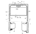
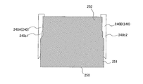
- FIG. 12A is a diagram showing a second modification of the refrigerator 1 according to the present embodiment, and is a diagram showing a state in which the shelf 250 is placed on the rail portion 240.
- FIG. 12B is a diagram illustrating a state where the shelf 250 illustrated in FIG. 12A is removed from the rail portion 240. Note that the description of the housing 2 and the like is omitted in FIGS. 12A and 12B.
- the rail part 240 includes a first rail part 240A and a second rail part 240B.
- the first rail portion 240A includes a first upper rail (not shown) and a first lower rail 240b1.
- the second rail portion 240B includes a second upper rail (not shown) and a second lower rail 240b2.
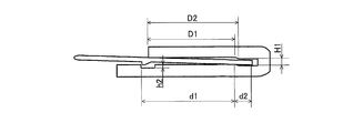
- the first lower rail 240b1 and the second lower rail 240b2 have a first interval Dt1 in the front interval in the depth direction, and a first interval Dt1 in the front portion in the depth direction. Is also a small second interval Dt2.
- the shelf 250 is formed with a wide portion 251 having a width d1 larger than the first interval Dt1 and a depth direction deeper than the wide portion 251, a width d2 smaller than the wide portion 251, and the first 2 and a back portion 252 having a width d2 larger than the interval Dt2 (referred to as configuration C).
- the shelf 250 can be rotated without pulling the shelf 250 to the front end of the rail portion 240 when the shelf 250 is attached or detached. Therefore, it becomes easy to avoid contact between the shelf 250 and the refrigerator compartment door 3 and the refrigerator compartment door 4. That is, the user can easily attach and detach the shelf 250.
- the refrigerator 1 according to the modified example 2 includes the configuration C and at least one of the configurations A1 to A7 described in the embodiment.
- the refrigerator 1 according to the second modification includes the configuration C, at least one of the configurations B1 to B3 described in the first modification, and at least one of the configurations A1 to A7 described in the embodiment.
- Refrigerator 2 housing, 2A 1st surface, 2B 2nd surface, 2C 3rd surface, 3 cold room door, 4 cold room door, 5 ice making room door, 6 switching room door, 7 freezer room door, 8 Vegetable room door, 10 cold room, 10A case, 10B case, 10C ice making water tank, 11 ice making room, 11A ice making case, 12 switching room, 12A switching room case, 13 freezing room, 13A freezing room case, 13B freezing room case , 14 vegetable room, 14A vegetable room case, 14B vegetable room case, 15 machine room, 20 compressor, 21 heat exchanger, 22 cooling fan, 23 switching room damper, 24 cold room damper, 30 cold room duct, 31 switching room duct, 32 vegetable room duct, 40 rail section, 40A first rail section, 40B second rail section, 40a upper rail, 0a1, first upper rail, 40a2, second upper rail, 40b lower rail, 40b1, first lower rail, 40b2, second lower rail, 40c convex portion, 40c1, first convex portion, 40,
Landscapes
- Engineering & Computer Science (AREA)
- Chemical & Material Sciences (AREA)
- Combustion & Propulsion (AREA)
- Physics & Mathematics (AREA)
- Mechanical Engineering (AREA)
- Thermal Sciences (AREA)
- General Engineering & Computer Science (AREA)
- Refrigerator Housings (AREA)
Abstract
La présente invention concerne un réfrigérateur équipé de rails (40A, 40B) qui sont disposés dans un compartiment de stockage de façon à supporter les extrémités latérales d'une étagère. Les rails comprennent : des rails supérieurs (40a) qui sont agencés au-dessus des extrémités latérales de l'étagère et qui sont formés de façon à s'étendre dans la direction de la profondeur du compartiment de stockage ; et des rails inférieurs (40b) qui sont agencés sous les extrémités latérales de l'étagère et qui sont formés de façon à s'étendre dans la direction de la profondeur du compartiment de stockage, et qui entrent en contact avec la surface inférieure de l'étagère. Les rails supérieurs sont pourvus de saillies (40c) qui sont agencées à l'arrière dans la direction de la profondeur du compartiment de stockage et qui font face à la surface supérieure des extrémités latérales de l'étagère.
Priority Applications (3)
| Application Number | Priority Date | Filing Date | Title |
|---|---|---|---|
| JP2018506510A JP6534491B2 (ja) | 2016-03-22 | 2016-03-22 | 冷蔵庫 |
| CN201690000310.6U CN207147046U (zh) | 2016-03-22 | 2016-03-22 | 冰箱 |
| PCT/JP2016/058885 WO2017163295A1 (fr) | 2016-03-22 | 2016-03-22 | Réfrigérateur |
Applications Claiming Priority (1)
| Application Number | Priority Date | Filing Date | Title |
|---|---|---|---|
| PCT/JP2016/058885 WO2017163295A1 (fr) | 2016-03-22 | 2016-03-22 | Réfrigérateur |
Publications (1)
| Publication Number | Publication Date |
|---|---|
| WO2017163295A1 true WO2017163295A1 (fr) | 2017-09-28 |
Family
ID=59900069
Family Applications (1)
| Application Number | Title | Priority Date | Filing Date |
|---|---|---|---|
| PCT/JP2016/058885 Ceased WO2017163295A1 (fr) | 2016-03-22 | 2016-03-22 | Réfrigérateur |
Country Status (3)
| Country | Link |
|---|---|
| JP (1) | JP6534491B2 (fr) |
| CN (1) | CN207147046U (fr) |
| WO (1) | WO2017163295A1 (fr) |
Cited By (4)
| Publication number | Priority date | Publication date | Assignee | Title |
|---|---|---|---|---|
| CN110411129A (zh) * | 2019-07-01 | 2019-11-05 | 合肥华凌股份有限公司 | 搁架组件及制冷设备 |
| WO2023135787A1 (fr) * | 2022-01-17 | 2023-07-20 | 三菱電機株式会社 | Réfrigérateur |
| JP2024033355A (ja) * | 2022-08-30 | 2024-03-13 | 国立大学法人大阪大学 | 医薬品用保冷庫 |
| WO2024075963A1 (fr) * | 2022-10-07 | 2024-04-11 | 삼성전자주식회사 | Réfrigérateur |
Citations (6)
| Publication number | Priority date | Publication date | Assignee | Title |
|---|---|---|---|---|
| JP2004116967A (ja) * | 2002-09-30 | 2004-04-15 | Hitachi Home & Life Solutions Inc | 冷蔵庫 |
| JP2005121328A (ja) * | 2003-10-20 | 2005-05-12 | Mitsubishi Electric Corp | 冷蔵庫 |
| JP2007044107A (ja) * | 2005-08-08 | 2007-02-22 | Okamura Corp | 棚板への前縁部材の取付構造 |
| US20090206717A1 (en) * | 2006-05-10 | 2009-08-20 | Koo Bon-Young | Installation structure of shelf assembly for refrigerator and refrigerator comprising the same |
| US20100181884A1 (en) * | 2009-01-16 | 2010-07-22 | Whirlpool Corporation | Refrigerator shelf with glass receiving slot |
| JP2013204881A (ja) * | 2012-03-28 | 2013-10-07 | Sharp Corp | 冷蔵庫 |
Family Cites Families (4)
| Publication number | Priority date | Publication date | Assignee | Title |
|---|---|---|---|---|
| DE58906490D1 (de) * | 1988-10-28 | 1994-02-03 | Klinotec Med Tech | Schrankanordnung. |
| DE4133453A1 (de) * | 1991-10-09 | 1993-04-15 | Licentia Gmbh | Kuehlgeraet mit abstellplatte |
| US5893620A (en) * | 1993-07-26 | 1999-04-13 | Whirlpool Corporation | Multiple shelf support system in common refrigerator liner |
| KR100702996B1 (ko) * | 2005-08-11 | 2007-04-06 | 엘지전자 주식회사 | 냉장고용 선반어셈블리의 장착구조 |
-
2016
- 2016-03-22 WO PCT/JP2016/058885 patent/WO2017163295A1/fr not_active Ceased
- 2016-03-22 JP JP2018506510A patent/JP6534491B2/ja not_active Expired - Fee Related
- 2016-03-22 CN CN201690000310.6U patent/CN207147046U/zh not_active Expired - Fee Related
Patent Citations (6)
| Publication number | Priority date | Publication date | Assignee | Title |
|---|---|---|---|---|
| JP2004116967A (ja) * | 2002-09-30 | 2004-04-15 | Hitachi Home & Life Solutions Inc | 冷蔵庫 |
| JP2005121328A (ja) * | 2003-10-20 | 2005-05-12 | Mitsubishi Electric Corp | 冷蔵庫 |
| JP2007044107A (ja) * | 2005-08-08 | 2007-02-22 | Okamura Corp | 棚板への前縁部材の取付構造 |
| US20090206717A1 (en) * | 2006-05-10 | 2009-08-20 | Koo Bon-Young | Installation structure of shelf assembly for refrigerator and refrigerator comprising the same |
| US20100181884A1 (en) * | 2009-01-16 | 2010-07-22 | Whirlpool Corporation | Refrigerator shelf with glass receiving slot |
| JP2013204881A (ja) * | 2012-03-28 | 2013-10-07 | Sharp Corp | 冷蔵庫 |
Cited By (6)
| Publication number | Priority date | Publication date | Assignee | Title |
|---|---|---|---|---|
| CN110411129A (zh) * | 2019-07-01 | 2019-11-05 | 合肥华凌股份有限公司 | 搁架组件及制冷设备 |
| WO2023135787A1 (fr) * | 2022-01-17 | 2023-07-20 | 三菱電機株式会社 | Réfrigérateur |
| JPWO2023135787A1 (fr) * | 2022-01-17 | 2023-07-20 | ||
| JP7668906B2 (ja) | 2022-01-17 | 2025-04-25 | 三菱電機株式会社 | 冷蔵庫 |
| JP2024033355A (ja) * | 2022-08-30 | 2024-03-13 | 国立大学法人大阪大学 | 医薬品用保冷庫 |
| WO2024075963A1 (fr) * | 2022-10-07 | 2024-04-11 | 삼성전자주식회사 | Réfrigérateur |
Also Published As
| Publication number | Publication date |
|---|---|
| JPWO2017163295A1 (ja) | 2018-06-07 |
| JP6534491B2 (ja) | 2019-06-26 |
| CN207147046U (zh) | 2018-03-27 |
Similar Documents
| Publication | Publication Date | Title |
|---|---|---|
| EP3009775B1 (fr) | Réfrigérateur | |
| US9574819B2 (en) | Refrigerator | |
| US20150192347A1 (en) | Refrigerator | |
| KR20140047360A (ko) | 도어가스켓의 응결 방지용 냉장고 | |
| WO2017163295A1 (fr) | Réfrigérateur | |
| JP4848332B2 (ja) | 冷蔵庫 | |
| JP5882808B2 (ja) | 冷蔵庫 | |
| JP2015017736A (ja) | 冷蔵庫 | |
| WO2018109937A1 (fr) | Réfrigérateur | |
| JP5783983B2 (ja) | 冷蔵庫 | |
| JP6723441B2 (ja) | 冷蔵庫 | |
| US20150192351A1 (en) | Refrigerator | |
| JP6719646B2 (ja) | 冷蔵庫 | |
| TW202334596A (zh) | 冰箱 | |
| JP2014013112A (ja) | 冷蔵庫 | |
| JP5960447B2 (ja) | 冷蔵庫 | |
| JP2013057472A (ja) | 冷蔵庫 | |
| JP2017083046A (ja) | 冷蔵庫 | |
| JP5378322B2 (ja) | 冷蔵庫 | |
| JP2007064593A (ja) | 冷蔵庫 | |
| JP2006194571A (ja) | 冷蔵庫 | |
| JP6236623B2 (ja) | 冷蔵庫 | |
| JP2024058181A (ja) | 冷蔵庫 | |
| JP2020122633A (ja) | 冷蔵庫、ガラス部材 | |
| JP2024058180A (ja) | 冷蔵庫 |
Legal Events
| Date | Code | Title | Description |
|---|---|---|---|
| ENP | Entry into the national phase |
Ref document number: 2018506510 Country of ref document: JP Kind code of ref document: A |
|
| NENP | Non-entry into the national phase |
Ref country code: DE |
|
| 121 | Ep: the epo has been informed by wipo that ep was designated in this application |
Ref document number: 16895333 Country of ref document: EP Kind code of ref document: A1 |
|
| 122 | Ep: pct application non-entry in european phase |
Ref document number: 16895333 Country of ref document: EP Kind code of ref document: A1 |