WO2017163302A1 - Appareil de commande - Google Patents
Appareil de commande Download PDFInfo
- Publication number
- WO2017163302A1 WO2017163302A1 PCT/JP2016/058928 JP2016058928W WO2017163302A1 WO 2017163302 A1 WO2017163302 A1 WO 2017163302A1 JP 2016058928 W JP2016058928 W JP 2016058928W WO 2017163302 A1 WO2017163302 A1 WO 2017163302A1
- Authority
- WO
- WIPO (PCT)
- Prior art keywords
- cpu
- shared memory
- error
- access
- circuit
- Prior art date
- Legal status (The legal status is an assumption and is not a legal conclusion. Google has not performed a legal analysis and makes no representation as to the accuracy of the status listed.)
- Ceased
Links
Images


Classifications
-
- G—PHYSICS
- G06—COMPUTING OR CALCULATING; COUNTING
- G06F—ELECTRIC DIGITAL DATA PROCESSING
- G06F15/00—Digital computers in general; Data processing equipment in general
- G06F15/16—Combinations of two or more digital computers each having at least an arithmetic unit, a program unit and a register, e.g. for a simultaneous processing of several programs
- G06F15/163—Interprocessor communication
- G06F15/167—Interprocessor communication using a common memory, e.g. mailbox
-
- G—PHYSICS
- G06—COMPUTING OR CALCULATING; COUNTING
- G06F—ELECTRIC DIGITAL DATA PROCESSING
- G06F11/00—Error detection; Error correction; Monitoring
- G06F11/07—Responding to the occurrence of a fault, e.g. fault tolerance
- G06F11/0703—Error or fault processing not based on redundancy, i.e. by taking additional measures to deal with the error or fault not making use of redundancy in operation, in hardware, or in data representation
- G06F11/0706—Error or fault processing not based on redundancy, i.e. by taking additional measures to deal with the error or fault not making use of redundancy in operation, in hardware, or in data representation the processing taking place on a specific hardware platform or in a specific software environment
- G06F11/0721—Error or fault processing not based on redundancy, i.e. by taking additional measures to deal with the error or fault not making use of redundancy in operation, in hardware, or in data representation the processing taking place on a specific hardware platform or in a specific software environment within a central processing unit [CPU]
-
- G—PHYSICS
- G06—COMPUTING OR CALCULATING; COUNTING
- G06F—ELECTRIC DIGITAL DATA PROCESSING
- G06F11/00—Error detection; Error correction; Monitoring
- G06F11/07—Responding to the occurrence of a fault, e.g. fault tolerance
- G06F11/0703—Error or fault processing not based on redundancy, i.e. by taking additional measures to deal with the error or fault not making use of redundancy in operation, in hardware, or in data representation
- G06F11/0766—Error or fault reporting or storing
- G06F11/0772—Means for error signaling, e.g. using interrupts, exception flags, dedicated error registers
-
- G—PHYSICS
- G06—COMPUTING OR CALCULATING; COUNTING
- G06F—ELECTRIC DIGITAL DATA PROCESSING
- G06F9/00—Arrangements for program control, e.g. control units
- G06F9/06—Arrangements for program control, e.g. control units using stored programs, i.e. using an internal store of processing equipment to receive or retain programs
- G06F9/46—Multiprogramming arrangements
- G06F9/52—Program synchronisation; Mutual exclusion, e.g. by means of semaphores
-
- G—PHYSICS
- G06—COMPUTING OR CALCULATING; COUNTING
- G06F—ELECTRIC DIGITAL DATA PROCESSING
- G06F9/00—Arrangements for program control, e.g. control units
- G06F9/06—Arrangements for program control, e.g. control units using stored programs, i.e. using an internal store of processing equipment to receive or retain programs
- G06F9/46—Multiprogramming arrangements
- G06F9/54—Interprogram communication
- G06F9/544—Buffers; Shared memory; Pipes
-
- G—PHYSICS
- G06—COMPUTING OR CALCULATING; COUNTING
- G06F—ELECTRIC DIGITAL DATA PROCESSING
- G06F11/00—Error detection; Error correction; Monitoring
- G06F11/07—Responding to the occurrence of a fault, e.g. fault tolerance
- G06F11/0703—Error or fault processing not based on redundancy, i.e. by taking additional measures to deal with the error or fault not making use of redundancy in operation, in hardware, or in data representation
- G06F11/0751—Error or fault detection not based on redundancy
Definitions
- Embodiments of the present invention relate to a control device.
- a control apparatus including a processor that executes a predetermined task is known.
- a plurality of processors may be provided.
- each processor may be configured to transmit and receive data via one shared memory.
- each processor in order to acquire data from other processors, each processor periodically and repeatedly accesses the shared memory in addition to the preset task, and the data from the other processors is written into the shared memory. It is necessary to perform processing to check whether or not. For this reason, conventionally, the processing load when transmitting and receiving data via the shared memory may increase.
- the control device includes a first device including a first control unit, a second device including a second control unit, a shared memory, and a first circuit.
- the shared memory is configured to be shared by the first device and the second device.
- the first circuit is configured to acquire information related to access from the second device when the second control unit accesses the shared memory, and output the acquired information related to access to the first device. .
- FIG. 1 is an exemplary block diagram illustrating a configuration of a control device according to the first embodiment.
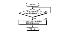
- FIG. 2 is an exemplary flowchart showing processing executed by the diagnostic circuit according to the first embodiment.
- FIG. 3 is an exemplary flowchart showing processing executed by the monitoring circuit according to the first embodiment.
- FIG. 4 is an exemplary flowchart showing processing executed by the CPU of the master device according to the first embodiment.
- FIG. 5 is an exemplary block diagram illustrating a configuration of a control device according to the second embodiment.
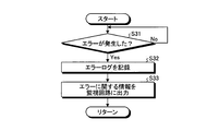
- FIG. 6 is an exemplary flowchart showing processing executed by the diagnostic circuit according to the second embodiment.
- FIG. 7 is an exemplary flowchart showing processing executed by the monitoring circuit according to the second embodiment.
- FIG. 8 is an exemplary flowchart showing processing executed by the CPU of the master device according to the second embodiment.
- the control device 100 is a controller used in the instrumentation field, the electric control field, the power field, and the like.
- the control device 100 includes a mother board 10, a master device 20, and a plurality of slave devices 30.
- the master device 20 and the slave device 30 are connected to the motherboard 10.
- the master device 20 is an example of a “first device”
- the slave device 30 is an example of a “second device”.
- FIG. 1 shows an example in which three slave devices 30 are provided, the number of slave devices 30 may be four or more, or may be two or less.
- the motherboard 10 includes a shared memory 11 and an arbitration circuit 12.
- the shared memory 11 is configured to be shared by the master device 20 and the slave device 30. That is, the master device 20 and the slave device 30 are configured to transmit and receive data via the shared memory 11.
- the arbitration circuit 12 is configured to arbitrate competition for access to the shared memory 11. That is, the arbitration circuit 12 is configured to avoid contention between the access to the shared memory 11 by the master device 20 and the access to the shared memory 11 by the slave device 30.
- the master device 20 includes a CPU (Central Processing Unit) 21 configured to be able to perform various processes based on data acquired from the slave device 30 via the shared memory 11.
- the master device 20 is connected to the host device 40 and is configured to be able to output the result of processing by the CPU 21 to the host device 40.
- the CPU 21 is an example of a “first control unit”.
- the slave device 30 is connected to an input / output device (I / O device) 50.
- the slave device 30 includes a CPU 31 configured to perform various processes based on data input via the I / O device 50 and to output the processing results to the shared memory 11.
- the CPU 31 is an example of a “second control unit”.
- the slave device 30 also includes a peripheral device 32 such as a memory.
- the motherboard 10 acquires information related to the access from the slave device 30, and transmits the acquired information related to access to the master device 20. And a monitoring circuit 13 configured to do so.
- the monitoring circuit 13 is configured by hardware such as an FPGA (Field Programmable Gate Array).
- the monitoring circuit 13 is an example of a “first circuit”.
- the information related to access includes information indicating the address of the shared memory 11 accessed by the CPU 31, information indicating whether the access performed by the CPU 31 is data writing or data reading, and the like. For example, information relating to such access is obtained by monitoring a bus (see a straight line L with an arrow in FIG. 1) between the CPU 31 and the shared memory 11 and intercepting a signal output from the CPU 31 to the shared memory 11. It can be obtained by.
- the slave device 30 acquires the information related to the access by monitoring the bus (see the straight line L with an arrow in FIG. 1) between the CPU 31 and the shared memory 11, and the acquired access.
- a diagnostic circuit 33 configured to transmit information about the to the monitoring circuit 13.
- the diagnostic circuit 33 is configured by hardware such as an FPGA (Field Programmable Gate Array).
- the diagnostic circuit 33 is an example of a “second circuit”.
- the master device 20 includes a register 22 configured to store information related to access acquired from the monitoring circuit 13.
- the CPU 21 of the master device 20 is configured to access the shared memory 11 based on the register 22.
- the diagnostic circuit 33 monitors information indicating the address of the shared memory 11 to which the CPU 31 has written data as information related to access. It is configured to output to the circuit 13. Then, the monitoring circuit 13 writes in the register 22 of the master device 20 information that can specify which CPU 31 has written the data in which address of the shared memory 11 based on the information acquired from the diagnostic circuit 33. It is configured.
- the register 22 is configured to output an interrupt signal to the CPU 21 when the above information is written by the diagnostic circuit 33. Then, when an interrupt signal is input from the register 22, the CPU 21 temporarily stops processing currently being performed, reads information from the register 22, and accesses the shared memory 11 based on the read information, whereby the CPU 31 Is configured to acquire data written to the shared memory 11 from the shared memory 11.
- the diagnostic circuit 33 first determines whether or not the CPU 31 of the slave device 30 has accessed the shared memory 11 in step S1. More specifically, the diagnostic circuit 33 monitors the bus between the CPU 31 and the shared memory 11 (see a straight line L with an arrow in FIG. 1), and a signal indicating that the CPU 31 has accessed the shared memory 11 is a bus. It is determined whether it is output above. The process in step S1 is repeated until it is determined by the CPU 31 that the shared memory 11 has been accessed. If it is determined in step S1 that the CPU 31 has accessed the shared memory 11, the process proceeds to step S2.
- step S2 the diagnostic circuit 33 outputs information related to the access to the shared memory 11 performed by the CPU 31 to the monitoring circuit 13 of the motherboard 10.
- the information related to access includes information indicating the address of the shared memory 11 accessed by the CPU 31, information indicating whether the access performed by the CPU 31 is data writing or data reading, and the like.
- Information regarding access is generated based on a signal intercepted from a bus between the CPU 31 and the shared memory 11 (see a straight line L with an arrow in FIG. 1). Then, the process returns.
- the monitoring circuit 13 first determines in step S11 whether or not information related to access to the shared memory 11 performed by the CPU 31 of the slave device 30 has been input from the diagnostic circuit 33. to decide. The process of step S11 is repeated until it is determined that information related to access is input from the diagnostic circuit 33. If it is determined in step S11 that information related to access has been input from the diagnostic circuit 33, the process proceeds to step S12.
- step S ⁇ b> 12 the monitoring circuit 13 outputs information related to access input from the diagnostic circuit 33 to the register 22 of the master device 20. For example, when the CPU 31 of the slave device 30 writes data to the shared memory 11, the monitoring circuit 13 writes information or the like that can specify to which address of the shared memory 11 the CPU 31 has written data to the register 22. Then, the process returns.
- the CPU 21 first determines whether or not the information related to the access to the shared memory 11 performed by the CPU 31 is stored in the register 22 in step S21. For example, assuming that the register 22 is configured to output an interrupt signal to the CPU 21 when information related to access is stored, the CPU 21 inputs the interrupt signal from the register 22 to itself in step S21. It is determined whether or not. The process in step S21 is repeated until it is determined that information related to access is stored in the register 22. If it is determined in step S21 that information related to access is stored in the register 22, the process proceeds to step S22.
- step S22 the CPU 21 accesses the shared memory 11 based on the information stored in the register 22. For example, when the CPU 31 writes data to the shared memory 11 to pass data to the master device 20, the register 22 monitors information that can identify the address of the shared memory 11 to which the CPU 31 has written data. In step S22, the CPU 21 reads the information written in the register 22 by the monitoring circuit 13 from the register 22 and accesses the shared memory 11 based on the read information in step S22. The data written to 11 is acquired from the shared memory 11. Then, the process returns.
- the control device 100 when the CPU 31 of the slave device 30 accesses the shared memory 11, the control device 100 according to the first embodiment acquires information related to the access from the slave device 30 and relates to the acquired access.
- a monitoring circuit 13 that outputs information to the master device 20 is provided.
- the slave device 30 acquires information related to access by monitoring a bus (see the straight line L with an arrow in FIG. 1) between the CPU 31 and the shared memory 11, and information related to the acquired access. Is provided to the monitoring circuit 13. Thereby, the information regarding access can be easily acquired only by intercepting the signal output to the bus between the CPU 31 and the shared memory 11 by the diagnostic circuit 33. That is, since it is not necessary for the CPU 31 to perform the process of outputting the information related to access to the monitoring circuit 13, the processing load on the CPU 31 can be reduced.
- the master device 20 includes a register 22 that stores information related to access acquired from the monitoring circuit 13, and the CPU 21 of the master device 20 accesses the shared memory 11 based on the register 22. It is configured as follows. As a result, it is possible to easily acquire information related to the access performed by the CPU 31 of the slave device 30 to the shared memory 11 only by monitoring the register 22. Thereby, access to the shared memory 11 can be performed efficiently.
- the control device 100a according to the second embodiment includes a motherboard 10a, a master device 20a, and a plurality of slave devices 30a, like the control device 100 according to the first embodiment.
- the master device 20a is an example of a “first device”
- the slave device 30a is an example of a “second device”.
- FIG. 5 shows an example in which three slave devices 30a are provided, the number of slave devices 30a may be four or more, or may be two or less.
- the motherboard 10a according to the second embodiment includes a shared memory 11, an arbitration circuit 12, and a monitoring circuit 13a.
- the monitoring circuit 13a is an example of a “first circuit”.
- the master device 20a according to the second embodiment includes a CPU 21a and a register 22.
- the CPU 21a is an example of a “first control unit”.
- the slave device 30a according to the second embodiment includes a CPU 31a, a peripheral device 32, and a diagnostic circuit 33a.
- the CPU 31a is an example of a “second control unit”
- the diagnostic circuit 33a is an example of a “second circuit”.
- the diagnostic circuit 33a acquires information on errors that may occur in the CPU 31a by monitoring the bus (see the straight line L with an arrow in FIG. 5) between the CPU 31a and the shared memory 11. Is configured to do.
- the diagnostic circuit 33a sends an output signal from the CPU 31a to the bus (FIG. 5). It is configured to determine whether or not the CPU 31a is performing an operation deviating from the above setting by intercepting via a straight line L with an arrow).
- the diagnostic circuit 33a determines that the CPU 31a is performing an operation deviating from the above setting, that is, when it is determined that some error has occurred in the CPU 31a, the details of the error are recorded as the error log 34. At the same time, information related to the error is output to the monitoring circuit 13a of the motherboard 10a.
- the monitoring circuit 13a is configured to output the acquired information about the error to the master device 20a when the information about the error is acquired from the slave device 30a. More specifically, when the monitoring circuit 13a obtains the information related to the error from the slave device 30a, the monitoring circuit 13a sets information that can identify which slave device 30a has an error in the CPU 31a of the master device 20a. It is configured to write to the register 22.
- the CPU 21a is configured to perform exception processing based on the register 22. More specifically, the register 22 is configured to output an interrupt signal to the CPU 21a when the above information is written by the diagnostic circuit 33a. Then, when an interrupt signal is input from the register 22, the CPU 21a is configured to temporarily stop the currently performed process and perform an exception process. Examples of exception processing include processing for initializing the slave device 30a including the CPU 31a in which an error has occurred, and processing for disconnecting the slave device 30a including the CPU 31a in which an error has occurred from the system.
- the diagnostic circuit 33a first determines in step S31 whether or not an error has occurred in the CPU 31a of the slave device 30a. More specifically, the diagnostic circuit 33a monitors the bus (see the straight line L with an arrow in FIG. 5) between the CPU 31a and the shared memory 11, and intercepts an output signal from the CPU 31a from the bus, thereby It is determined whether or not the operation is out of the setting. The process of step S31 is repeated until it is determined that an error has occurred in the CPU 31a. If it is determined in step S31 that an error has occurred in the CPU 31a, the process proceeds to step S32.
- step S32 the diagnostic circuit 33a records an error log 34 indicating details of an error that has occurred in the CPU 31a. Then, the process proceeds to step S33.
- step S33 the diagnostic circuit 33a outputs information related to the error that has occurred in the CPU 31a to the monitoring circuit 13a of the motherboard 10a.
- Information about the error is generated based on a signal intercepted from the bus between the CPU 31a and the shared memory 11 (see a straight line L with an arrow in FIG. 5). Then, the process returns.
- the monitoring circuit 13a first determines in step S41 whether or not information regarding an error that has occurred in the CPU 31a of the slave device 30a has been input from the diagnostic circuit 33a. The process of step S41 is repeated until it is determined that information regarding an error has been input from the diagnostic circuit 33a. If it is determined in step S41 that information regarding an error has been input from the diagnostic circuit 33a, the process proceeds to step S42.
- step S42 the monitoring circuit 13a outputs information related to the error input from the diagnostic circuit 33a to the register 22 of the master device 20a. More specifically, the monitoring circuit 13a writes in the register 22 information that can specify which slave device 30a has an error in the CPU 31a. Then, the process returns.
- the CPU 21a first determines whether or not information regarding an error that has occurred in the CPU 31a is stored in the register 22 in step S51. For example, assuming that the register 22 is configured to output an interrupt signal to the CPU 21a when information relating to an error is stored, the CPU 21a receives the interrupt signal from the register 22 itself in step S51. It is determined whether or not. The process of step S51 is repeated until it is determined that the information regarding the error is stored in the register 22. If it is determined in step S51 that information related to the error has been stored in the register 22, the process proceeds to step S52.
- step S52 the CPU 21a executes exception processing based on the information regarding the error stored in the register 22. That is, when an error occurs in the CPU 31a, the monitoring circuit 13a writes in the register 22 information that can specify which slave device 30a has an error in the CPU 31a. The information written in the register 22 by the monitoring circuit 13a is read from the register 22, and exception processing is performed on the slave device 30a having the CPU 31a specified based on the read information. Examples of exception processing include processing for initializing the slave device 30a including the CPU 31a in which the error has occurred and processing for disconnecting the slave device 30a including the CPU 31a in which the error has occurred from the system as described above. Conceivable. Then, the process returns.
- the control device 100a when an error occurs in the CPU 31a of the slave device 30a, acquires information related to the error from the slave device 30a, and acquires the acquired information related to the error to the master device 20a. Is provided with a monitoring circuit 13a. Thereby, it is possible to reduce the processing burden when detecting whether or not errors have occurred.
- each processor detects whether or not an error has occurred using a so-called healthy counter using a common storage medium (shared memory). It was. For example, each time a predetermined task ends normally, each processor stores data indicating that no error has occurred in the shared memory, and monitors the stored data to each other. , It was detected whether or not errors occurred with each other. As described above, conventionally, each processor has to perform various processes in addition to a preset task in order to detect whether or not an error has occurred. There was a thing.
- control device 100a since the control device 100a according to the second embodiment includes the monitoring circuit 13a as described above, the fact that an error has occurred in the CPU 31a is mastered by the monitoring circuit 13a, which is hardware independent of the CPU 31a. The device 20a is notified. Therefore, according to the second embodiment, since it is not necessary to periodically perform a process of repeatedly accessing the shared memory 11 in order to detect whether or not an error has occurred, the processing load can be reduced. Can do.
- the slave device 30a acquires information about the error by monitoring the bus (see the straight line L with an arrow in FIG. 5) between the CPU 31a and the shared memory 11, and information about the acquired error Is provided to the monitoring circuit 13a.
- the information regarding an error can be easily acquired only by intercepting the signal output to the bus between the CPU 31a and the shared memory 11 by the diagnostic circuit 33a. That is, since it is not necessary to cause the CPU 31a to perform processing for outputting information relating to the error to the monitoring circuit 13a, the processing load on the CPU 31a can be reduced.
- the error log 34 indicates in detail what kind of operation the CPU 31a has performed. Can be recorded.
- the master device 20a includes a register 22 that stores information about an error acquired from the monitoring circuit 13a.
- the CPU 21a is configured to execute exception processing based on the register 22. Yes. As a result, it is possible to easily obtain information regarding the error only by monitoring the register 22.
Landscapes
- Engineering & Computer Science (AREA)
- Theoretical Computer Science (AREA)
- Physics & Mathematics (AREA)
- General Engineering & Computer Science (AREA)
- General Physics & Mathematics (AREA)
- Software Systems (AREA)
- Computer Hardware Design (AREA)
- Quality & Reliability (AREA)
- Debugging And Monitoring (AREA)
- Hardware Redundancy (AREA)
Abstract
L'invention porte, dans un mode de réalisation, sur un appareil de commande qui est pourvu : d'un premier appareil comprenant une première unité de commande ; d'un second appareil comprenant une seconde unité de commande ; d'une mémoire partagée et d'un premier circuit. La mémoire partagée est configurée de sorte à être partagée par les premier et second appareils. Le premier circuit est conçu pour acquérir, lorsque la seconde unité de commande a accès à la mémoire partagée, des informations concernant l'accès, auprès du second appareil, et pour transmettre, au premier appareil, les informations acquises concernant l'accès.
Priority Applications (3)
| Application Number | Priority Date | Filing Date | Title |
|---|---|---|---|
| PCT/JP2016/058928 WO2017163302A1 (fr) | 2016-03-22 | 2016-03-22 | Appareil de commande |
| CN201680002199.9A CN107835990A (zh) | 2016-03-22 | 2016-03-22 | 控制装置 |
| US15/511,201 US20190012292A1 (en) | 2016-03-22 | 2016-03-22 | Control device |
Applications Claiming Priority (1)
| Application Number | Priority Date | Filing Date | Title |
|---|---|---|---|
| PCT/JP2016/058928 WO2017163302A1 (fr) | 2016-03-22 | 2016-03-22 | Appareil de commande |
Publications (1)
| Publication Number | Publication Date |
|---|---|
| WO2017163302A1 true WO2017163302A1 (fr) | 2017-09-28 |
Family
ID=59900040
Family Applications (1)
| Application Number | Title | Priority Date | Filing Date |
|---|---|---|---|
| PCT/JP2016/058928 Ceased WO2017163302A1 (fr) | 2016-03-22 | 2016-03-22 | Appareil de commande |
Country Status (3)
| Country | Link |
|---|---|
| US (1) | US20190012292A1 (fr) |
| CN (1) | CN107835990A (fr) |
| WO (1) | WO2017163302A1 (fr) |
Families Citing this family (2)
| Publication number | Priority date | Publication date | Assignee | Title |
|---|---|---|---|---|
| EP4213024A1 (fr) * | 2022-01-12 | 2023-07-19 | Bull SAS | Procédé de partage d'image, programme d'ordinateur et système mettant en oeuvre un tel procédé |
| CN115617560A (zh) * | 2022-11-02 | 2023-01-17 | 地平线征程(杭州)人工智能科技有限公司 | 一种芯片监控方法及装置 |
Citations (5)
| Publication number | Priority date | Publication date | Assignee | Title |
|---|---|---|---|---|
| JPS5537643A (en) * | 1978-09-08 | 1980-03-15 | Fujitsu Ltd | Multiprocessor system trouble processing system |
| JPH0384640A (ja) * | 1989-08-29 | 1991-04-10 | Fujitsu Ltd | 障害情報通知方式 |
| JP2004078683A (ja) * | 2002-08-20 | 2004-03-11 | Toshiba Corp | コンピュータシステムおよび共有メモリ制御方法 |
| JP2014026347A (ja) * | 2012-07-24 | 2014-02-06 | Auto Network Gijutsu Kenkyusho:Kk | 監視装置、コンピュータプログラム及び監視方法 |
| JP2016066273A (ja) * | 2014-09-25 | 2016-04-28 | 株式会社東芝 | 制御装置 |
-
2016
- 2016-03-22 CN CN201680002199.9A patent/CN107835990A/zh not_active Withdrawn
- 2016-03-22 WO PCT/JP2016/058928 patent/WO2017163302A1/fr not_active Ceased
- 2016-03-22 US US15/511,201 patent/US20190012292A1/en not_active Abandoned
Patent Citations (5)
| Publication number | Priority date | Publication date | Assignee | Title |
|---|---|---|---|---|
| JPS5537643A (en) * | 1978-09-08 | 1980-03-15 | Fujitsu Ltd | Multiprocessor system trouble processing system |
| JPH0384640A (ja) * | 1989-08-29 | 1991-04-10 | Fujitsu Ltd | 障害情報通知方式 |
| JP2004078683A (ja) * | 2002-08-20 | 2004-03-11 | Toshiba Corp | コンピュータシステムおよび共有メモリ制御方法 |
| JP2014026347A (ja) * | 2012-07-24 | 2014-02-06 | Auto Network Gijutsu Kenkyusho:Kk | 監視装置、コンピュータプログラム及び監視方法 |
| JP2016066273A (ja) * | 2014-09-25 | 2016-04-28 | 株式会社東芝 | 制御装置 |
Also Published As
| Publication number | Publication date |
|---|---|
| US20190012292A1 (en) | 2019-01-10 |
| CN107835990A (zh) | 2018-03-23 |
Similar Documents
| Publication | Publication Date | Title |
|---|---|---|
| US8874959B2 (en) | Information processing apparatus, image forming apparatus, and information processing program | |
| US8645767B2 (en) | Scalable I/O adapter function level error detection, isolation, and reporting | |
| US8656228B2 (en) | Memory error isolation and recovery in a multiprocessor computer system | |
| WO2016127600A1 (fr) | Procédé et appareil de gestion d'exception | |
| US9411695B2 (en) | Provisioning memory in a memory system for mirroring | |
| WO2017163302A1 (fr) | Appareil de commande | |
| CN111190548B (zh) | 一种基于SPDK的ceph分布式存储性能提升方法、装置及设备 | |
| JP6241323B2 (ja) | スイッチ装置、情報処理装置、情報処理装置の制御方法および情報処理装置の制御プログラム | |
| US9672173B2 (en) | Shared PCI interrupt line management | |
| JP2016066273A (ja) | 制御装置 | |
| JP2005149501A (ja) | Dmaを使用して拡張カードでメモリをテストするためのシステムおよび方法 | |
| US10210110B2 (en) | Associating data buses and management bus connections for peripheral devices | |
| US8032720B2 (en) | Memory access monitoring apparatus and related method | |
| JP2014186423A (ja) | 監視システム | |
| JP2012163995A (ja) | 情報処理装置 | |
| JP2005149503A (ja) | Dmaを使用してメモリをテストするためのシステムおよび方法 | |
| US20110145655A1 (en) | Input/output hub to input/output device communication | |
| CN116775125A (zh) | 用于无异常地处理无效浮点运算的系统和方法 | |
| US20160077942A1 (en) | Storage system and test method for testing pci express interface | |
| CN113176964B (zh) | 基于mpu的ssd固件检错方法、装置、计算机设备及存储介质 | |
| TWI854647B (zh) | 匯流排異常檢測和處理方法、裝置、系統、設備及媒體 | |
| US20160378096A1 (en) | Numerical controller and numerical control system in which the controller is connected by network | |
| JP2013025440A (ja) | 情報処理装置および障害処理方法 | |
| US11003474B2 (en) | Semiconductor device for providing a virtualization technique | |
| JP2011164669A (ja) | メモリアクセス制御システムおよびメモリアクセス制御方法 |
Legal Events
| Date | Code | Title | Description |
|---|---|---|---|
| NENP | Non-entry into the national phase |
Ref country code: DE |
|
| 121 | Ep: the epo has been informed by wipo that ep was designated in this application |
Ref document number: 16895338 Country of ref document: EP Kind code of ref document: A1 |
|
| 122 | Ep: pct application non-entry in european phase |
Ref document number: 16895338 Country of ref document: EP Kind code of ref document: A1 |
|
| NENP | Non-entry into the national phase |
Ref country code: JP |