WO2017163305A1 - Système de circulation de milieu thermique - Google Patents
Système de circulation de milieu thermique Download PDFInfo
- Publication number
- WO2017163305A1 WO2017163305A1 PCT/JP2016/058948 JP2016058948W WO2017163305A1 WO 2017163305 A1 WO2017163305 A1 WO 2017163305A1 JP 2016058948 W JP2016058948 W JP 2016058948W WO 2017163305 A1 WO2017163305 A1 WO 2017163305A1
- Authority
- WO
- WIPO (PCT)
- Prior art keywords
- heat medium
- heat
- conduit
- heating
- circuit
- Prior art date
- Legal status (The legal status is an assumption and is not a legal conclusion. Google has not performed a legal analysis and makes no representation as to the accuracy of the status listed.)
- Ceased
Links
Images


Classifications
-
- F—MECHANICAL ENGINEERING; LIGHTING; HEATING; WEAPONS; BLASTING
- F24—HEATING; RANGES; VENTILATING
- F24D—DOMESTIC- OR SPACE-HEATING SYSTEMS, e.g. CENTRAL HEATING SYSTEMS; DOMESTIC HOT-WATER SUPPLY SYSTEMS; ELEMENTS OR COMPONENTS THEREFOR
- F24D3/00—Hot-water central heating systems
-
- F—MECHANICAL ENGINEERING; LIGHTING; HEATING; WEAPONS; BLASTING
- F24—HEATING; RANGES; VENTILATING
- F24H—FLUID HEATERS, e.g. WATER OR AIR HEATERS, HAVING HEAT-GENERATING MEANS, e.g. HEAT PUMPS, IN GENERAL
- F24H4/00—Fluid heaters characterised by the use of heat pumps
- F24H4/02—Water heaters
Definitions
- the present invention relates to a heat medium circulation system that performs a heating operation for circulating a heat medium to a heater.
- a hot water heating and hot water supply device disclosed in the following Patent Document 1 includes a heat source device that heats a fluid, a circulation unit that circulates the fluid heated by the heat source device, a hot water storage tank that stores hot water, and a flow path switching unit. It is possible to carry out heating operation and heat storage operation.
- the technique of Patent Document 1 has the following problems.
- the flow rate of the heat medium passing through the radiator or the heating appliance is equal to or lower than the flow rate passing through the heat source device.
- it is desirable that the flow rate of the heat medium passing through the heater is high.
- it is desirable that the flow rate of the heat medium passing through the heat pump type heating device is low.
- the present invention has been made to solve the above-described problems, and an object of the present invention is to provide a heat medium circulation system capable of reducing the temperature unevenness of the heater and achieving a highly efficient operation. .
- a heat medium circulation system is a heat medium circulation system that performs a heating operation for circulating a heat medium to a heating appliance, a heating unit that heats the heat medium, and a heating unit that passes through the heating unit and the heating appliance during the heating operation.
- a first valve device for varying a ratio between a flow rate of the heat medium flowing through one circuit and a flow rate of the heat medium flowing through the second circuit passing through the heating appliance without passing through the heating means, and means for controlling the first valve device Are provided.
- the heat medium circulation system of the present invention it is possible to reduce both the temperature unevenness of the heater and a highly efficient operation.
- FIG. 1 is a diagram illustrating a heat medium circulation system according to a first embodiment.
- FIG. 3 is a diagram showing a heating operation in a first mode in the first embodiment. It is a figure which shows the heating operation of the 2nd mode in Embodiment 1.
- FIG. 3 is a diagram illustrating a bypass operation in the first embodiment.
- FIG. 5 is a diagram showing a heating operation in a third mode in the first embodiment. It is a figure which shows the thermal storage driving
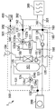
- FIG. 1 is a diagram illustrating a heat medium circulation system according to the first embodiment.
- the heat medium circulation system 1 of Embodiment 1 shown in FIG. 1 is a heat pump hot water supply / heating system.
- the heat medium circulation system 1 includes a tank unit 100, a heat pump device 200, and a control device 500.
- the tank unit 100 and the heat pump device 200 are connected via a first conduit 121, a third conduit 123, and electrical wiring (not shown).
- the tank unit 100 may be installed outdoors or indoors.
- the heat pump apparatus 200 may be installed outdoors.
- the heat medium circulation system 1 of the present embodiment has a configuration in which the heat pump device 200 and the tank unit 100 are separated. Not only in such a configuration, the tank unit 100 and the heat pump device 200 may be integrated.
- the heat pump device 200 is an example of a heating unit that heats a liquid heat medium.
- the heat pump apparatus 200 includes a compressor that compresses a refrigerant, a heat exchanger, a decompression device that decompresses the refrigerant, an evaporator that evaporates the refrigerant, and a refrigerant circuit (circular refrigerant pipe that connects these devices in an annular shape). (Not shown).
- Refrigerant may be CO 2.
- the heat pump device 200 operates a heat pump cycle, that is, a refrigeration cycle with this refrigerant circuit.
- the heat exchanger exchanges heat between the high-temperature and high-pressure refrigerant compressed by the compressor and the heat medium.
- the decompression device expands the high-pressure refrigerant after passing through the heat exchanger into a low-pressure refrigerant.
- the decompression device may be an expansion valve.
- the evaporator exchanges heat between the low-pressure refrigerant and the fluid.
- the fluid may be, for example, outside air, groundwater, drainage, or solar hot water.
- the heat pump apparatus 200 may include a blower, a pump, and the like (not shown) that send the fluid to the evaporator.
- the heat medium may be water.
- the heat medium may be a liquid heat medium other than water, such as an aqueous calcium chloride solution, an aqueous ethylene glycol solution, or alcohol.
- the heating means is not limited to the heat pump device 200.
- the heating means may be a combustion heating device that heats with the combustion heat of a fuel such as gas, kerosene, heavy oil, or coal.
- the heating means may be a device that heats the heat medium by solar heat.
- the tank unit 100 includes a heat storage tank 101 that stores a heat medium.
- a temperature stratification is formed in which the upper side is high temperature and the lower side is low temperature.
- the heater 300 for heating the room and the tank unit 100 are connected via external conduits 301 and 302.
- the heat medium circulation system 1 can perform a heating operation.
- the heating operation is an operation in which the heat medium is circulated to the heating appliance 300.
- the heater 300 may include, for example, at least one of a floor heating panel installed under the floor, a radiator or panel heater installed on an indoor wall surface, and a fan convector.
- a plurality of heating appliances 300 may be connected.
- the connection method when a plurality of heating appliances 300 are connected may be any of a combination of series, parallel, series, and parallel. When a plurality of heating appliances 300 are provided, their types may be the same or different.
- the control device 500 is an example of a control unit that controls the operation of the heat medium circulation system 1. Each actuator and each sensor included in the heat medium circulation system 1 are electrically connected to the control device 500. In the illustrated configuration, a control device 500 is disposed in the tank unit 100.
- Each function of the control device 500 may be realized by a processing circuit.
- the processing circuit of the control device 500 may include at least one processor 501 and at least one memory 502.
- each function of the control device 500 may be realized by software, firmware, or a combination of software and firmware.
- At least one of software and firmware may be described as a program.
- At least one of software and firmware may be stored in at least one memory 502.
- the at least one processor 501 may realize each function of the control device 500 by reading and executing a program stored in the at least one memory 502.
- the at least one memory 502 may include a nonvolatile or volatile semiconductor memory, a magnetic disk, or the like.
- the processing circuit of the control device 500 may include at least one dedicated hardware.
- the processing circuit may be, for example, a single circuit, a composite circuit, a programmed processor, a parallel programmed processor, an ASIC (Application Specific Integrated Circuit), or an FPGA (Field- Programmable Gate Array) or a combination thereof.
- the function of each part of the control device 500 may be realized by a processing circuit. Further, the functions of the respective units of the control device 500 may be collectively realized by a processing circuit. A part of each function of the control device 500 may be realized by dedicated hardware, and the other part may be realized by software or firmware.
- the processing circuit may realize each function of the control device 500 by hardware, software, firmware, or a combination thereof.
- the configuration is not limited to the configuration in which the operation of the heat medium circulation system 1 is controlled by a single control device, and the operation of the heat medium circulation system 1 may be controlled by cooperation of a plurality of control devices. .
- a user interface device such as a remote controller 400 may be connected to the control device 500.
- the remote controller 400 may be installed indoors.
- Remote controller 400 may be in a room with heating appliance 300.
- the remote controller 400 may be integrated with the heating appliance 300.
- the remote controller 400 and the control device 500 may be connected so as to be able to perform data communication in both directions by wireless or wired.
- the user may input a command related to the operation of the heat medium circulation system 1 and a change in the set value to the remote controller 400.
- the remote controller 400 may transmit the input information to the control device 500.
- the remote controller 400 may include a room temperature sensor.
- the remote controller 400 may transmit information regarding the current room temperature and the target room temperature set by the user to the control device 500.
- the control device 500 may control the operation of the heat medium circulation system 1 based on the information received from the remote controller 400.
- the heat medium circulation system 1 includes a heat medium circuit network.
- the network is formed by a group of conduits described later.
- the tank unit 100 includes a pump 122, a first valve device 132, and a second valve device 124.
- the pump 122 causes the heating medium of the network to flow.
- the first valve device 132 and the second valve device 124 switch the path through which the heat medium flows in the circuit network.
- the first valve device 132 has a first inlet 132a, a second inlet 132b, a first outlet 132c, and a second outlet 132d.
- the first valve device 132 may be a four-way valve.
- the second valve device 124 has an inlet 124a, a first outlet 124b, and a second outlet 124c.
- the second valve device 124 may be a three-way valve.
- the tank unit 100 includes connection ports 161 and 162.
- the external conduit 301 connects between the outlet of the heat medium of the heating appliance 300 and the connection port 161.
- the external conduit 302 connects between the connection port 162 and the inlet of the heat medium of the heater 300.
- the heat medium is sent from the tank unit 100 to the heater 300 through the external conduit 302.
- the heat medium that has passed through the heating appliance 300 returns to the tank unit 100 through the external conduit 301.
- the first conduit 121 connects between the outlet of the pump 122 and the inlet of the heat medium of the heat pump device 200. A part of the first conduit 121 passes through a space outside the tank unit 100 and the heat pump device 200.
- the second conduit 163 connects between the connection port 161 and the inlet of the pump 122. The heat medium returned from the heater 300 through the external conduit 301 is guided to the inlet of the pump 122 through the second conduit 163.
- the third conduit 123 connects between the heat medium outlet of the heat pump device 200 and the inlet 124a of the second valve device 124. A part of the third conduit 123 passes through a space outside the tank unit 100 and the heat pump device 200.
- the tank upper pipe 125 connects between the first outlet 124 b of the second valve device 124 and the upper part of the heat storage tank 101.
- the fourth conduit 131 connects the second outlet 124c of the second valve device 124 and the first inlet 132a of the first valve device 132.
- the tank lower pipe 120 connects between the lower part of the heat storage tank 101 and the branch part 165 located in the middle of the second conduit 163.
- the fifth conduit 164 has one end connected to the first outlet 132 c of the first valve device 132 and the other end connected to the connection port 162.
- the fifth conduit 164 passes the heat medium toward the heater 300. The heat medium is sent to the heating appliance 300 through the fifth conduit 164 and the external conduit 302.
- the sixth conduit 127 connects between the branching portion 166 in the middle of the first conduit 121 and the second inlet 132b of the first valve device 132.
- the seventh conduit 134 connects between the second outlet 132 d of the first valve device 132 and the branch portion 165 at a position in the middle of the second conduit 163.
- the branch portion 165 to which the seventh conduit 134 is connected is located at the same position as the branch portion 165 to which the tank lower pipe 120 is connected, but is not limited to such a configuration, The position may be different.
- the temperature of the heat medium supplied from the tank unit 100 to the heating appliance 300 is referred to as “supply temperature”.
- the supply temperature can be detected by the supply temperature sensor 133 installed in the fifth conduit 164.
- the tank unit 100 includes a heat source conduit 150, a pump 151, a hot water supply heat exchanger 152, a water supply pipe 153, and a hot water supply pipe 154.
- the hot water supply heat exchanger 152 exchanges heat between the high-temperature heat medium supplied from the heat storage tank 101 and the water supplied from the water supply pipe 153.
- the heat source conduit 150 connects between the upper part of the heat storage tank 101 and the inlet of the heat medium of the hot water supply heat exchanger 152 and between the outlet of the heat medium of the hot water heat exchanger 152 and the lower part of the heat storage tank 101. And a portion.
- a pump 151 is connected to a heat source conduit 150 on the way between the outlet of the heat medium of the hot water supply heat exchanger 152 and the lower part of the heat storage tank 101.
- the upstream side of the water supply pipe 153 is connected to a water source such as a water supply.
- the downstream end of the water supply pipe 153 is connected to the water inlet of the hot water supply heat exchanger 152.
- the upstream end of the hot water supply pipe 154 is connected to the hot water outlet of the hot water supply heat exchanger 152.
- the downstream side of the hot water supply pipe 154 is connected to a hot water tap (not shown).
- the operation is as follows.
- the control device 500 may detect the presence or absence of a water flow using a flow switch or a flow sensor (not shown) installed in the water supply pipe 153.
- the pump 151 is operated, and a high-temperature heat medium is supplied from the upper part of the heat storage tank 101 to the hot water supply heat exchanger 152.
- Water heated by the hot water supply heat exchanger 152 is supplied to the hot water tap through the hot water supply pipe 154.
- the heat medium whose temperature has decreased while passing through the hot water supply heat exchanger 152 flows into the lower part of the heat storage tank 101.
- the pump 122 and the pump 151 may have variable output or rotational speed.
- the pump 122 and the pump 151 may include a DC motor of a pulse width modulation control type that can change an output or a rotation speed by a speed command voltage from the control device 500.
- the first valve device 132 includes a first state in which the first inlet 132a is in communication with the first outlet 132c, a second state in which the first inlet 132a is in communication with the second outlet 132d, and a second inlet 132b in the first outlet 132c. And a fourth state in which both the first inlet 132a and the second inlet 132b are in communication with the first outlet 132c.
- the first valve device 132 includes an actuator (not shown) for performing the switching.
- the actuator may be a stepping motor, for example.
- the second valve device 124 has a first state in which the inlet 124a communicates with the first outlet 124b and blocks the second outlet 124c, and a second state in which the inlet 124a communicates with the second outlet 124c and blocks the first outlet 124b. You can switch between states.
- the second valve device 124 includes an actuator (not shown) for performing the switching.
- the actuator may be a stepping motor, for example.
- the heating operation performed by the heat medium circulation system 1 of the present embodiment includes a first mode and a second mode.
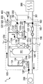
- FIG. 2 is a diagram showing the heating operation in the first mode in the first embodiment.
- the heating operation in the first mode will be described with reference to FIG.
- the controller 500 controls as follows during the heating operation in the first mode.
- the first valve device 132 is in the first state.
- the 2nd valve apparatus 124 will be in a 2nd state.
- the heat pump device 200 and the pump 122 are operated.
- the heat medium discharged from the pump 122 is a first conduit 121, a heat pump device 200, a third conduit 123, a second valve device 124, a fourth conduit 131, a first valve device 132, a fifth conduit 164, an external conduit 302, It returns to the pump 122 via the heating appliance 300, the external conduit 301, and the second conduit 163 in this order.
- a circuit in which the heat medium circulates in such a path is hereinafter referred to as a “first circuit”.
- the first circuit is a circuit that passes through the heat pump device 200 and the heating appliance 300.
- the flow rate of the heat medium that passes through the heat pump device 200 is equal to the flow rate of the heat medium that passes through the heating appliance 300.
- the difference between the temperature of the heat medium exiting from the heat pump apparatus 200, that is, the temperature after heating, and the temperature of the heat medium entering the heat pump apparatus 200, that is, the temperature before heating, is large. desirable. That is, in order to increase the operating efficiency of the heat pump apparatus 200, it is desirable to relatively reduce the flow rate of the heat medium passing through the heat pump apparatus 200.
- the control device 500 may operate the pump 122 so that the flow rate of the heat medium passing through the heat pump device 200 becomes a relatively low value, for example, 3 L / min.
- the supply temperature to the heater 300 is relatively high.
- the heating appliance 300 including a radiator is not easily affected by temperature unevenness.
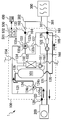
- FIG. 3 is a diagram showing the heating operation in the second mode in the first embodiment.
- the heating operation in the second mode will be described with reference to FIG.
- the control device 500 controls as follows.
- the first valve device 132 is in the fourth state.
- the 2nd valve apparatus 124 will be in a 2nd state.
- the heat pump device 200 and the pump 122 are operated.
- the flow of the heat medium discharged from the pump 122 is bifurcated at the branching section 166.
- a part of the flow of the heat medium discharged from the pump 122 flows into the sixth conduit 127.
- the remaining flow of the heat medium discharged from the pump 122 passes through the first conduit 121 as it is to the heat pump device 200.
- the heat medium directed to the heat pump device 200 flows through the first circuit described above.
- the heat medium flowing into the sixth conduit 127 returns to the pump 122 via the first valve device 132, the fifth conduit 164, the external conduit 302, the heating appliance 300, the external conduit 301, and the second conduit 163 in this order.
- a circuit in which the heat medium circulates in such a path is hereinafter referred to as a “second circuit”.
- the second circuit is a circuit that passes through the heating appliance 300 without passing through the heat pump device 200.
- the heat medium flowing through the first circuit and the heat medium flowing through the second circuit merge at the first valve device 132.
- the heat medium flowing through the first circuit is heated by the heat pump device 200.
- the heat medium flowing through the second circuit is not heated.
- the temperature of the heat medium flowing from the fourth conduit 131 of the first circuit into the first valve device 132 is higher than the temperature of the heat medium flowing into the first valve device 132 from the sixth conduit 127 of the second circuit.
- the high-temperature heat medium from the fourth conduit 131 and the low-temperature heat medium from the sixth conduit 127 are mixed in the first valve device 132, and then heated through the fifth conduit 164 and the external conduit 302. 300. Therefore, the supply temperature to the heating appliance 300 is lower than the temperature of the heat medium after being heated by the heat pump device 200.
- the first valve device 132 corresponds to a junction between the first circuit and the second circuit.
- the supply temperature sensor 133 is an example of a unit that detects the temperature of the heat medium from the junction to the heating appliance 300.
- the temperature of the heat medium decreases while passing through the heater 300.
- the temperature of the heat medium near the outlet of the heater 300 is lower than the temperature of the heat medium near the inlet of the heater 300.
- the difference between the temperature near the entrance of the heating appliance 300 and the temperature near the exit of the heating appliance 300 increases. If the flow rate of the heat medium passing through the heating appliance 300 is lowered, the temperature unevenness of the heating appliance 300 may occur. In order to reduce the temperature unevenness of the heater 300, it is desirable that the flow rate of the heat medium passing through the heater 300 is relatively high.
- the flow rate of the heat medium that passes through the heating appliance 300 is higher than the flow rate of the heat medium that passes through the heat pump device 200. Since the flow rate of the heat medium passing through the heating appliance 300 can be made higher than that in the first mode heating operation, the temperature unevenness of the heating appliance 300 can be reduced. In addition, the flow rate of the heat medium passing through the heat pump device 200 can be reduced. For this reason, the operating efficiency of the heat pump device 200 can be increased.
- a heater 300 including a floor heating panel may be easily affected by temperature unevenness.
- the heating device 300 including the floor heating panel it is desirable to lower the supply temperature of the heat medium as compared to, for example, the heating device 300 including the radiator.
- the heating appliance 300 including the floor heating panel it is preferable to mainly perform the heating operation in the second mode.
- the flow rate of the heat medium passing through the heat pump device 200 that is, the flow rate of the first circuit may be, for example, 3 L / min.
- the flow rate of the heat medium passing through the heating appliance 300 that is, the total flow rate of the first circuit and the second circuit may be, for example, 10 L / min. In this case, the flow rate of the second circuit is 7 L / min.
- the temperature unevenness of the heating appliance 300 can be more reliably reduced.
- the heating operation in the second mode corresponds to an operation in which a heat medium flows through both the first circuit and the second circuit.
- the ratio between the flow rate of the heat medium flowing through the first circuit and the flow rate of the heat medium flowing through the second circuit is 3: 7.
- the ratio between the flow rate of the heat medium flowing through the first circuit and the flow rate of the heat medium flowing through the second circuit is 10: 0. That is, the heating operation in the first mode corresponds to an operation in which the heat medium is passed through the first circuit without flowing the heat medium through the second circuit.
- the first valve device 132 can switch between the first mode heating operation and the second mode heating operation.
- the first valve device 132 can change the ratio of the flow rate of the heat medium flowing through the first circuit and the flow rate of the heat medium flowing through the second circuit. Therefore, the state of heating operation can be controlled more appropriately according to the situation.
- the flow rate of the heat medium passing through the heat pump device 200 is kept low.
- the flow rate of the heat medium passing through the heating appliance 300 can be increased or decreased. For this reason, it is possible to improve both the operating efficiency of the heat pump device 200 and to adjust the flow rate of the heat medium passing through the heating appliance 300.
- the first valve device 132 may be capable of continuously varying the ratio between the flow rate of the heat medium flowing through the first circuit and the flow rate of the heat medium flowing through the second circuit.
- the first valve device 132 may be capable of varying the ratio of the flow rate of the heat medium flowing through the first circuit and the flow rate of the heat medium flowing through the second circuit in multiple stages, that is, in a stepped manner.
- the control device 500 may control the first valve device 132 so that the supply temperature detected by the supply temperature sensor 133 falls within the target temperature range.
- the control device 500 controls the ratio of the flow rate of the heat medium flowing through the first circuit and the flow rate of the heat medium flowing through the second circuit so that the supply temperature detected by the supply temperature sensor 133 falls within the target temperature range. May be.
- the target temperature range may be determined according to the target room temperature set by the user and the current room temperature. By doing as mentioned above, the supply temperature to the heating appliance 300 can be controlled with higher accuracy.
- the ratio of the flow rate of the heat medium flowing through the first circuit and the flow rate of the heat medium flowing through the second circuit during the heating operation in the second mode may be, for example, between 1: 9 and 9: 1.
- the first valve device 132 sets the ratio of the flow rate of the heat medium flowing through the first circuit to the flow rate of the heat medium flowing through the second circuit between two different points between 1: 9 and 9: 1. It may be variable.
- the first valve device 132 may be configured such that the ratio between the flow rate of the heat medium flowing through the first circuit and the flow rate of the heat medium flowing through the second circuit cannot be 10: 0.
- the heat medium circulation system 1 may not be capable of heating operation in the first mode.
- the first valve device 132 only needs to be able to vary the ratio of the flow rate of the heat medium flowing through the first circuit and the flow rate of the heat medium flowing through the second circuit between at least two different points.
- the heat medium circulation system 1 can perform a bypass operation.
- the bypass operation is an operation in which a heat medium is passed through the bypass circuit.
- the bypass circuit is a circuit that passes through the heat pump device 200 without passing through the heat storage tank 101 and the heating appliance 300.
- FIG. 4 is a diagram illustrating a bypass operation in the first embodiment. Hereinafter, the bypass operation will be described with reference to FIG.
- the control device 500 controls as follows.
- the first valve device 132 is in the second state.
- the 2nd valve apparatus 124 will be in a 2nd state.
- the pump 122 is operated.
- the heat pump device 200 may be operated or may not be operated.
- the heat medium discharged from the pump 122 includes a first conduit 121, a heat pump device 200, a third conduit 123, a second valve device 124, a fourth conduit 131, a first valve device 132, a seventh conduit 134, a branching portion 165, It returns to the pump 122 via the second conduit 163 in this order.
- control device 500 When an abnormality such as an external factor or piping blockage occurs, there is a possibility that the heat medium cannot be circulated smoothly through the heating appliance 300.
- control device 500 generates a state in which the heat medium cannot be smoothly circulated in heating appliance 300 based on the circulation flow rate of the heat medium detected by flow sensor 126 during the heating operation. Can be detected.
- the control device 500 shifts to the bypass operation by switching the first valve device 132 from the first state or the fourth state to the second state. May be. By doing so, poor circulation of the heat medium can be reliably avoided, and the heat pump device 200 and the pump 122 can be more reliably protected.
- bypass operation is not limited to the above example performed using the first valve device 132.
- a bypass conduit (not shown) connecting between the second conduit 163 and the fifth conduit 164 and an on-off valve (not shown) for opening and closing the bypass conduit may be provided, and the bypass operation may be performed using the bypass conduit. .
- the heating operation performed by the heat medium circulation system 1 of the present embodiment further includes a third mode.
- FIG. 5 is a diagram showing the heating operation in the third mode in the first embodiment.
- the heating operation in the third mode will be described with reference to FIG.
- the heating operation in the third mode corresponds to an operation in which the heat medium is supplied to the second circuit without supplying the heat medium to the first circuit.
- the control device 500 controls as follows.
- the first valve device 132 is in the third state.
- the pump 122 is operated. Since the heat medium does not circulate in the second valve device 124, the second valve device 124 may be in any state. Since the heat medium does not circulate in the heat pump apparatus 200, the heat pump apparatus 200 may not be operated.
- the heat pump device 200 may perform a defrosting operation which will be described later.
- the heat medium circulates in the second circuit. That is, the heat medium discharged from the pump 122 is in the order of the branch portion 166, the sixth conduit 127, the first valve device 132, the fifth conduit 164, the external conduit 302, the heating appliance 300, the external conduit 301, and the second conduit 163. And return to the pump 122.
- the heat pump device 200 including an evaporator that absorbs heat from the outside air may perform a defrosting operation for removing frost attached to the evaporator.
- frost adhering to the evaporator is melted using the heat of the high-temperature refrigerant compressed by the compressor.
- the heat pump device 200 may switch the refrigerant circuit so that the high-temperature refrigerant compressed by the compressor flows to the evaporator.
- the heat pump device 200 cannot heat the heat medium.
- the control device 500 may control as follows. When the defrosting operation becomes necessary during the execution of the heating operation in the first mode or the second mode, the mode shifts to the heating operation in the third mode, and during the heating operation in the third mode, A defrosting operation may be performed. That is, the heating operation in the third mode and the defrosting operation of the heat pump device 200 may be performed in parallel. By doing so, the heating operation can be continued during the defrosting operation.
- the heating operation performed by the heat medium circulation system 1 of the present embodiment may further include a fourth mode.
- the heating operation in the fourth mode is an operation in which the heating operation in the first mode or the second mode and the heating operation in the third mode are alternately performed.
- FIG. 6 is a diagram showing a heat storage operation in the first embodiment.
- the heat storage operation is an operation in which the heat medium heated by the heat pump device 200 is stored in the heat storage tank 101.
- the heat storage operation will be described with reference to FIG.
- the control device 500 controls as follows.
- the second valve device 124 is in the first state.
- the heat pump device 200 and the pump 122 are operated.
- the first valve device 132 may be in the first state or in the second state. From the viewpoint of preventing a high-temperature heat medium from being unexpectedly supplied to the heating appliance 300 when the second valve device 124 does not switch to the first state due to a failure, the first valve device 132 is in the second state. It is desirable to keep it.
- heat storage operation it is as follows.
- the lower heat medium in the heat storage tank 101 flows out to the tank lower pipe 120.
- the heat medium reaches the heat pump device 200 via the branching portion 165, the second conduit 163, the pump 122, and the first conduit 121 in this order.
- the heat medium heated by the heat pump device 200 flows into the upper portion of the heat storage tank 101 through the third conduit 123, the second valve device 124, and the tank upper pipe 125 in this order.
- a path through which the heat medium flows is referred to as a “heat storage circuit”.
- the temperature of the heat medium flowing out from the heat pump device 200 is referred to as “exit temperature”.
- the outlet temperature can be detected by the outlet temperature sensor 128 installed in the third conduit 123.
- the control device 500 may control the operation of at least one of the pump 122 and the heat pump device 200 so that the outlet temperature detected by the outlet temperature sensor 128 becomes equal to the target temperature.
- the control device 500 may determine a target temperature for the heat storage operation according to information input to the remote controller 400.
- the control device 500 may perform the bypass operation of FIG. 4 after starting the heat pump device 200 and before starting the heat storage operation. In the bypass operation, the control device 500 may shift to the heat storage operation by switching the second valve device 124 after a predetermined time has elapsed or after the outlet temperature reaches the target temperature.
- control device 500 may perform the bypass operation of FIG. By doing so, the heat exchanger inside the heat pump apparatus 200 can be quickly cooled.
- the control device 500 ends the heating operation.
- the control device 500 may be configured as follows. First, the control device 500 stops the operation of the heat pump device 200 while continuing the operation of the pump 122. Next, the control device 500 compares the outlet temperature detected by the outlet temperature sensor 128 with the target temperature of the heat storage operation. When the outlet temperature is equal to or higher than the target temperature for the heat storage operation, the control device 500 switches the second valve device 124 to the first state and continues the operation of the pump 122. That is, a heat medium is passed through the heat storage circuit.
- the first valve device 132 may be in the first state or in the second state.
- the first valve device 132 is set as the second state. It is desirable to keep it. The following effects are acquired by doing as mentioned above. At the end of the heating operation, the residual heat of the heat medium in the conduit and the residual heat of the heat pump device 200 can be recovered in the heat storage tank 101. In that case, the temperature of the upper part of the thermal storage tank 101 does not fall.
- the heat medium can be circulated by the common pump 122 in any of the heating operation, the heat storage operation, and the bypass operation. For this reason, the number of pumps for flowing the heat medium can be reduced.
- Heat medium circulation system 100 tank unit, 101 heat storage tank, 120 tank lower pipe, 121 first conduit, 122 pump, 123 third conduit, 124 second valve device, 124a inlet, 124b first outlet, 124c second outlet , 125 tank upper pipe, 126 flow sensor, 127 sixth conduit, 128 outlet temperature sensor, 131 fourth conduit, 132 first valve device, 132a first inlet, 132b second inlet, 132c first outlet, 132d second outlet , 133 supply temperature sensor, 134 seventh conduit, 150 heat source conduit, 151 pump, 152 hot water heat exchanger, 153 water supply pipe, 154 hot water supply pipe, 161, 162 connection port, 163 second conduit, 164 fifth conduit, 165 166 bifurcation 200 heat pump apparatus, 300 heaters, 301 and 302 external conduit, 302 external conduit, 500 controller
Landscapes
- Engineering & Computer Science (AREA)
- Physics & Mathematics (AREA)
- Thermal Sciences (AREA)
- Chemical & Material Sciences (AREA)
- Combustion & Propulsion (AREA)
- Mechanical Engineering (AREA)
- General Engineering & Computer Science (AREA)
- Steam Or Hot-Water Central Heating Systems (AREA)
- Heat-Pump Type And Storage Water Heaters (AREA)
Abstract
L'invention concerne un système de circulation de milieu thermique (1) qui réalise une opération de chauffage pour faire circuler un milieu thermique vers un appareil de chauffage (300). Le système de circulation de milieu thermique (1) comprend : un dispositif de pompe à chaleur (200) qui chauffe le milieu thermique ; un premier dispositif de soupape (132) qui, pendant l'opération de chauffage, varie le rapport entre le débit du milieu thermique s'écoulant à travers un premier circuit, qui passe à travers le dispositif de pompe à chaleur (200) et l'appareil de chauffage (300), et le débit du milieu thermique s'écoulant à travers un second circuit, qui évite le dispositif de pompe à chaleur (200) et passe à travers l'appareil de chauffage (300) ; et un dispositif de commande (500) qui commande le premier dispositif de soupape (132).
Priority Applications (1)
| Application Number | Priority Date | Filing Date | Title |
|---|---|---|---|
| PCT/JP2016/058948 WO2017163305A1 (fr) | 2016-03-22 | 2016-03-22 | Système de circulation de milieu thermique |
Applications Claiming Priority (1)
| Application Number | Priority Date | Filing Date | Title |
|---|---|---|---|
| PCT/JP2016/058948 WO2017163305A1 (fr) | 2016-03-22 | 2016-03-22 | Système de circulation de milieu thermique |
Publications (1)
| Publication Number | Publication Date |
|---|---|
| WO2017163305A1 true WO2017163305A1 (fr) | 2017-09-28 |
Family
ID=59900026
Family Applications (1)
| Application Number | Title | Priority Date | Filing Date |
|---|---|---|---|
| PCT/JP2016/058948 Ceased WO2017163305A1 (fr) | 2016-03-22 | 2016-03-22 | Système de circulation de milieu thermique |
Country Status (1)
| Country | Link |
|---|---|
| WO (1) | WO2017163305A1 (fr) |
Cited By (1)
| Publication number | Priority date | Publication date | Assignee | Title |
|---|---|---|---|---|
| EP3779285A4 (fr) * | 2018-04-12 | 2021-04-21 | Mitsubishi Electric Corporation | Système de chauffage |
Citations (6)
| Publication number | Priority date | Publication date | Assignee | Title |
|---|---|---|---|---|
| JPS6272523U (fr) * | 1985-10-23 | 1987-05-09 | ||
| JP2006046702A (ja) * | 2004-07-30 | 2006-02-16 | Daikin Ind Ltd | 暖房装置 |
| JP2007333340A (ja) * | 2006-06-16 | 2007-12-27 | Corona Corp | ヒートポンプ式給湯装置 |
| JP2012013346A (ja) * | 2010-07-02 | 2012-01-19 | Panasonic Corp | 温水暖房給湯装置 |
| JP2012207882A (ja) * | 2011-03-30 | 2012-10-25 | Mitsubishi Electric Corp | 温水暖房機 |
| JP2014016075A (ja) * | 2012-07-06 | 2014-01-30 | Denso Corp | ハイブリッドシステム |
-
2016
- 2016-03-22 WO PCT/JP2016/058948 patent/WO2017163305A1/fr not_active Ceased
Patent Citations (6)
| Publication number | Priority date | Publication date | Assignee | Title |
|---|---|---|---|---|
| JPS6272523U (fr) * | 1985-10-23 | 1987-05-09 | ||
| JP2006046702A (ja) * | 2004-07-30 | 2006-02-16 | Daikin Ind Ltd | 暖房装置 |
| JP2007333340A (ja) * | 2006-06-16 | 2007-12-27 | Corona Corp | ヒートポンプ式給湯装置 |
| JP2012013346A (ja) * | 2010-07-02 | 2012-01-19 | Panasonic Corp | 温水暖房給湯装置 |
| JP2012207882A (ja) * | 2011-03-30 | 2012-10-25 | Mitsubishi Electric Corp | 温水暖房機 |
| JP2014016075A (ja) * | 2012-07-06 | 2014-01-30 | Denso Corp | ハイブリッドシステム |
Cited By (1)
| Publication number | Priority date | Publication date | Assignee | Title |
|---|---|---|---|---|
| EP3779285A4 (fr) * | 2018-04-12 | 2021-04-21 | Mitsubishi Electric Corporation | Système de chauffage |
Similar Documents
| Publication | Publication Date | Title |
|---|---|---|
| US9228765B2 (en) | Refrigeration cycle device | |
| US10697648B2 (en) | Heating and hot water supply system | |
| US10401038B2 (en) | Heat pump system | |
| JP6645593B2 (ja) | 熱媒体循環システム | |
| JP6520802B2 (ja) | 蓄熱システム | |
| EP3540324B1 (fr) | Système de circulation de milieu chauffant | |
| JP2010084975A (ja) | 暖房装置 | |
| JP6012530B2 (ja) | 貯湯式給湯装置 | |
| WO2017163305A1 (fr) | Système de circulation de milieu thermique | |
| JP2009264714A (ja) | ヒートポンプ温水システム | |
| JP5160141B2 (ja) | 給湯システム | |
| JP6143614B2 (ja) | 熱機器 | |
| JP2010266127A (ja) | ヒートポンプ式空調装置 | |
| JP2012007858A (ja) | ヒートポンプ式給湯機 | |
| JP2009109061A (ja) | 暖房パネルを備えたヒートポンプ式空調装置 | |
| WO2017158685A1 (fr) | Système de circulation de milieu chauffant | |
| JP6102793B2 (ja) | ヒートポンプ式暖房給湯装置 | |
| KR20110060096A (ko) | 냉매사이클 연동 물 순환 시스템 및 그 제어 방법 | |
| KR20090085371A (ko) | 히트 펌프 급탕기 및 그 제어 방법 | |
| JP2010084974A (ja) | 暖房装置 | |
| JP2011163572A (ja) | ヒートポンプ式暖房給湯装置 | |
| JP2018179455A (ja) | 温水式床暖房システムおよび温水式床暖房システムの運転方法 | |
| JP2015232425A (ja) | 貯湯式給湯機 | |
| JP2018004125A (ja) | 給湯システム |
Legal Events
| Date | Code | Title | Description |
|---|---|---|---|
| NENP | Non-entry into the national phase |
Ref country code: DE |
|
| 121 | Ep: the epo has been informed by wipo that ep was designated in this application |
Ref document number: 16895341 Country of ref document: EP Kind code of ref document: A1 |
|
| 122 | Ep: pct application non-entry in european phase |
Ref document number: 16895341 Country of ref document: EP Kind code of ref document: A1 |
|
| NENP | Non-entry into the national phase |
Ref country code: JP |