WO2017163312A1 - Dispositif de commande d'ascenseur et procédé de commande d'ascenseur - Google Patents
Dispositif de commande d'ascenseur et procédé de commande d'ascenseur Download PDFInfo
- Publication number
- WO2017163312A1 WO2017163312A1 PCT/JP2016/058992 JP2016058992W WO2017163312A1 WO 2017163312 A1 WO2017163312 A1 WO 2017163312A1 JP 2016058992 W JP2016058992 W JP 2016058992W WO 2017163312 A1 WO2017163312 A1 WO 2017163312A1
- Authority
- WO
- WIPO (PCT)
- Prior art keywords
- reactive current
- threshold
- power
- elevator
- elevator control
- Prior art date
- Legal status (The legal status is an assumption and is not a legal conclusion. Google has not performed a legal analysis and makes no representation as to the accuracy of the status listed.)
- Ceased
Links
Images

Classifications
-
- B—PERFORMING OPERATIONS; TRANSPORTING
- B66—HOISTING; LIFTING; HAULING
- B66B—ELEVATORS; ESCALATORS OR MOVING WALKWAYS
- B66B1/00—Control systems of elevators in general
- B66B1/24—Control systems with regulation, i.e. with retroactive action, for influencing travelling speed, acceleration, or deceleration
- B66B1/28—Control systems with regulation, i.e. with retroactive action, for influencing travelling speed, acceleration, or deceleration electrical
- B66B1/30—Control systems with regulation, i.e. with retroactive action, for influencing travelling speed, acceleration, or deceleration electrical effective on driving gear, e.g. acting on power electronics, on inverter or rectifier controlled motor
-
- H—ELECTRICITY
- H02—GENERATION; CONVERSION OR DISTRIBUTION OF ELECTRIC POWER
- H02M—APPARATUS FOR CONVERSION BETWEEN AC AND AC, BETWEEN AC AND DC, OR BETWEEN DC AND DC, AND FOR USE WITH MAINS OR SIMILAR POWER SUPPLY SYSTEMS; CONVERSION OF DC OR AC INPUT POWER INTO SURGE OUTPUT POWER; CONTROL OR REGULATION THEREOF
- H02M7/00—Conversion of AC power input into DC power output; Conversion of DC power input into AC power output
- H02M7/02—Conversion of AC power input into DC power output without possibility of reversal
- H02M7/04—Conversion of AC power input into DC power output without possibility of reversal by static converters
- H02M7/12—Conversion of AC power input into DC power output without possibility of reversal by static converters using discharge tubes with control electrode or semiconductor devices with control electrode
-
- H—ELECTRICITY
- H02—GENERATION; CONVERSION OR DISTRIBUTION OF ELECTRIC POWER
- H02M—APPARATUS FOR CONVERSION BETWEEN AC AND AC, BETWEEN AC AND DC, OR BETWEEN DC AND DC, AND FOR USE WITH MAINS OR SIMILAR POWER SUPPLY SYSTEMS; CONVERSION OF DC OR AC INPUT POWER INTO SURGE OUTPUT POWER; CONTROL OR REGULATION THEREOF
- H02M7/00—Conversion of AC power input into DC power output; Conversion of DC power input into AC power output
- H02M7/42—Conversion of DC power input into AC power output without possibility of reversal
- H02M7/44—Conversion of DC power input into AC power output without possibility of reversal by static converters
- H02M7/48—Conversion of DC power input into AC power output without possibility of reversal by static converters using discharge tubes with control electrode or semiconductor devices with control electrode
-
- H—ELECTRICITY
- H02—GENERATION; CONVERSION OR DISTRIBUTION OF ELECTRIC POWER
- H02M—APPARATUS FOR CONVERSION BETWEEN AC AND AC, BETWEEN AC AND DC, OR BETWEEN DC AND DC, AND FOR USE WITH MAINS OR SIMILAR POWER SUPPLY SYSTEMS; CONVERSION OF DC OR AC INPUT POWER INTO SURGE OUTPUT POWER; CONTROL OR REGULATION THEREOF
- H02M7/00—Conversion of AC power input into DC power output; Conversion of DC power input into AC power output
- H02M7/66—Conversion of AC power input into DC power output; Conversion of DC power input into AC power output with possibility of reversal
- H02M7/68—Conversion of AC power input into DC power output; Conversion of DC power input into AC power output with possibility of reversal by static converters
Definitions
- the present invention relates to an elevator control device and an elevator control method for improving control performance in elevator-specific travel control in which power running operation and regenerative operation are frequently switched.
- a short circuit prevention time Td for preventing a short circuit between devices is provided.
- the short-circuit prevention time Td cannot be shortened in proportion to the higher switching frequency in relation to the stable drive of the inverter and converter.
- Patent Document 1 realizes an operation that suppresses an increase in overhead voltage in the case of regeneration and suppresses a decrease in overhead voltage in the case of powering.
- Patent Document 1 The configuration as disclosed in Patent Document 1 is not appropriate from the following viewpoint to be applied to a converter that frequently switches between power running / regenerative operation, such as an elevator. That is, in an elevator control device, if the following characteristics of switching are poor, the desired output improvement performance cannot be obtained, and if the switching is not smooth, the running characteristics of the car are impaired, and the control performance is further improved. is required.
- the present invention has been made to solve the above-described problems, and an elevator control device and an elevator control capable of improving the tracking characteristics of switching between power running / regenerative operation and the traveling characteristics of the elevator.
- the purpose is to obtain a method.
- An elevator control device includes a converter that converts an AC power supplied via a reactor into a DC power and supplies the DC power to a motor of a hoist that drives the elevator, and an AC current of the AC power
- An elevator control device comprising: a controller that supplies a DC power source corresponding to a target value to a motor by performing switching of a converter while controlling a power factor by separating components into an active current and a reactive current.
- a reactive current command value is generated by setting a first threshold so as to make it difficult for the current to flow, and the second threshold is set so that the reactive current flows more easily during regenerative operation than during power running operation. And generates a reactive current command value to set the value.
- an elevator control method includes a converter that converts an alternating current power supplied via a reactor into a direct current power and supplies the direct current power to a motor of a hoist that drives the elevator, and an alternating current power supply
- An elevator control device comprising a controller that supplies a DC power source corresponding to a target value to a motor by switching a converter while controlling a power factor by separating an AC current component into an active current and a reactive current.
- An elevator control method that is applied and executed by a controller, comprising: a first step for determining whether the elevator is in a power running operation or a regenerative operation; and a reactive current command value for controlling the reactive current
- the reactive current command value is generated by setting the first threshold so that the reactive current is less likely to flow during powering operation than during regenerative operation.
- the timing at which the power running operation state and the regenerative operation state are switched during one run from the start to the stop is determined, and an appropriate reactive current command is generated according to each operation state. It has a configuration that can. As a result, it is possible to obtain an elevator control device and an elevator control method capable of improving the follow-up characteristics of switching between power running / regenerative operation and the traveling characteristics of the elevator.
- FIG. 1 is an overall configuration diagram of an elevator system including an elevator control device according to Embodiment 1 of the present invention. It is the figure which showed the time change of the effective electric current command IP * during the traveling control by the control apparatus of the elevator which concerns on Embodiment 1 of this invention. It is the figure which showed the threshold value change process performed with the reactive current control circuit contained in the controller of the control apparatus of the elevator which concerns on Embodiment 1 of this invention. It is the figure which showed the threshold value change process different from previous FIG. 5 performed with the reactive current control circuit contained in the controller of the control apparatus of the elevator which concerns on Embodiment 1 of this invention.
- FIG. 1 is a circuit configuration diagram including a control device for a PWM converter according to Embodiment 1 of the present invention.
- the PWM converter 1 is composed of a diode bridge circuit connected in reverse parallel with the self-extinguishing switch element, and an AC power source V AC is connected to the AC input side via an AC reactor 2.
- a filter capacitor 4 and a load 5 are connected in parallel on the DC output side of the PWM converter 1.
- the current detection circuit 6 detects the DC voltage V of the PWM converter 1.
- the voltage control circuit 7 compares the voltage command V * and the DC voltage V, and outputs an effective current command I P * so as to reduce the deviation.
- Phase detection circuit 9 the voltage of the AC power source, and outputs a phase signal theta PS.
- FIG. 1 illustrates the case where the current of the R phase and S phase of the three phases is detected by the current detector
- the present invention is not limited to such a configuration.
- the same effect can be obtained by adopting a configuration that detects the current of any two phases or all three phases of the three phases.
- Active current control circuit 14 the active current command I P * outputted from the voltage control circuit 7, based on a deviation between the active current I P computed by the current detection circuit 17, the effective voltage command e of PWM converter 1 Calculate P * .
- reactive current control circuit 15 a reactive current command I Q * calculated by the reactive current reference circuit 18 to be described later, based on a deviation between the reactive current I Q computed by the current detection circuit 17, PWM converter 1 The reactive voltage command e Q * is calculated.
- PWM control circuit 16 an active voltage instruction e P *, a reactive voltage command e Q *, and a power supply voltage V AC phase signal theta PS, outputs a switching command SW of the PWM converter 1 to the self-extinguishing type switching elements To do.
- the voltage control circuit 7, the active current control circuit 14, the reactive current control circuit 15, the PWM control circuit 16, and the reactive current reference circuit 18 send the switching command SW based on the detection results of the detection circuits.
- the technique for calculating the reactive current command I Q * by the reactive current reference circuit 18 has the technical feature of the present invention, and will be described in detail with reference to FIG. .
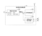
- FIG. 2 is a diagram showing an internal configuration of the reactive current reference circuit 18 according to the first embodiment of the present invention.
- the reactive current reference circuit 18 in the first embodiment includes a threshold determination circuit 18a, a square sum component calculation circuit 18b, and a power factor control circuit 18c.
- the threshold determination circuit 18a uses the following equation (1) to calculate the effective current command I P When * is negative, that is, during regenerative operation in which the PWM converter 1 reversely converts DC power into AC power, the threshold value used for power factor control in the subsequent stage is calculated by using the following equation (2).
- I P * ⁇ 0, threshold Vlim (1)
- I P * ⁇ 0, threshold Vlim ⁇ Vd (2)
- Vlim is a component determined by a voltage limit value that can be output by the PWM converter 1.
- ⁇ Vd is a correction voltage component of the vertical short circuit prevention time Td, and is calculated, for example, as the following expression (3).
- ⁇ Vd DC bus voltage [V] ⁇ upper and lower short-circuit prevention time [sec] ⁇ Switching frequency [Hz] (3)
- the square sum component calculation circuit 18b calculates the square sum of the effective voltage command e P * and the reactive voltage command e Q * . Then, the power factor control circuit 18c generates the reactive current command Iq * based on the deviation between the threshold calculated by the threshold determination circuit 18a and the square sum calculated by the square sum component calculation circuit 18b.
- the threshold is calculated so that Vlim and ⁇ Vd are also in the same dimension as the square sum component. Further, in the case of comparison using the square root signal of the sum of squares, the threshold is calculated so that Vlim and ⁇ Vd have the same dimensions as the square root signal.
- Td correction in the PWM converter 1 turns into surplus output on the power running side and acts as insufficient output on the regeneration side. Further, in order to improve the voltage utilization rate of the PWM converter 1, an operation corresponding to field weakening control referred to by a motor is performed by passing a reactive current.
- the PWM converter 1 when the PWM converter 1 has a high switching frequency, the ratio of the Td correction voltage increases, leading to a decrease in the voltage utilization rate. Therefore, in the present invention, it is determined whether the PWM converter 1 is in the power running operation or the regenerative operation based on the active current command value or the like, and the threshold for power factor control that takes into account the Td correction voltage is dynamically determined according to the determination result. It is changed and set.
- the reactive current command Ip * can be generated in accordance with the power running operation / regenerative operation with better tracking accuracy than in the past, and the voltage utilization factor of the converter can be improved.
- the AC reactor 2 can be reduced in size when the PWM converter is operated at a high switching frequency using a high-speed switching device such as SiC. In addition, it is possible to perform power conversion without deteriorating the voltage utilization rate more than necessary.
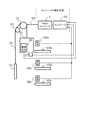
- FIG. 3 is an overall configuration diagram of an elevator system including the elevator control device according to Embodiment 1 of the present invention.
- the controller 30 in FIG. 3 corresponds to the controller 30 that controls the PWM converter 1 shown in FIG.
- the load 5 in FIG. 1 corresponds to the motor of the hoisting machine 31.
- the motor of the hoisting machine 31 will be described simply as the hoisting machine 31.
- the cage 35 is connected by a main rope 33, and the main rope 33 is wound around a hoisting machine 31 and connected to a weight 34 via a deflecting wheel 32.
- the hoisting machine 31 obtains a drive command 39 from the controller 30 and moves the car 35 up and down.
- the drive command 39 travels so that the car 35 is directed to the target landing when the passenger operates each of the landing operation panels 38a to 38c in the landings 40a to 40c or the in-car operation panel 36 in the car 35.
- the direction is set and commanded from the controller 30.
- the scale device 37 installed in the car or the like detects the load in the car 35 so that it can be determined whether the movement of the car is powering or regenerating. Then, the controller 30 can determine whether the elevator is started in the power running operation or the regenerative operation based on the traveling direction and the load in the car 35.
- the controller 30 transmits the determination result of powering / regeneration to the threshold value determination circuit 18a in the reactive current reference circuit 18 shown in FIG. That is, the reactive current reference circuit 18 can know whether the power running operation or the regenerative operation is activated from the determination result based on the traveling direction and the load in the car 35 at the time of activation.
- the reactive current reference circuit 18 appropriately changes the threshold for power factor control as described above, so that elevator control is executed at a high switching frequency. The reduction of the voltage utilization rate can be suppressed.
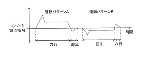
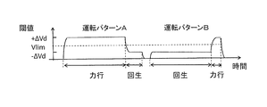
- FIG. 4 is a diagram showing a time change of the effective current command I P * during the traveling control of the elevator according to Embodiment 1 of the present invention. More specifically, FIG. 4 shows the time transition of the converter current command value in the following two operation patterns A and B.
- Driving pattern A Driving pattern starting from powering operation from the first floor to the second floor by powering operation, and switching from powering operation to regenerative operation when arriving at the second floor
- driving pattern B Starting from regenerative operation from the second floor to the third floor, starting operation by regenerative operation, and driving pattern that switches from regenerative operation to power running operation when arriving at the third floor
- the control by the controller 30 when executing such an operation pattern A or operation pattern B will be described below, divided into STEP1 to STEP3.
- ⁇ STEP 1> Processing at Start-up
- the controller 30 is started as a power running operation or a regenerative operation depending on the combination of the load in the car 35 detected by the scale device 37 and the traveling direction of the car 35. It can be judged. Specifically, the controller 30 can determine whether the operation is a power running operation or a regenerative operation in the following cases 1 to 4.
- Case 1 When the load in the car is greater than or equal to the weight of the weight 34 and the traveling direction is the upward direction, it is determined as power running.
- Case 2 The load in the car is less than the weight of the weight 34, and When the traveling direction is the upward direction, it is determined as regenerative operation.
- Case 3 When the load in the car is heavier than the weight 34 and when the traveling direction is the downward direction, it is determined as regenerative operation.
- Case 4 Car When the internal load is equal to or less than the weight of the weight 34 and the traveling direction is the descending direction, it is determined that the power running operation is performed.
- the controller 30 uses the threshold value corresponding to the power running operation or the regenerative operation determined in STEP 1 until the deceleration to stop at the target floor is started after the start.
- the reactive current command I Q * is generated and the elevator traveling control is executed.
- ⁇ STEP 3> The travel control after the start of deceleration
- the controller 30 switches from the acceleration or constant speed state to the deceleration state, thereby switching from the power running operation to the regenerative operation as shown in FIG. Estimate when to switch to driving. It should be noted that the controller 30 can estimate the timing at which the operating state is switched from the information of the operating pattern, and detect it from the positive and negative values of the active current command I P * as described above with reference to FIG. Is also possible.
- the controller 30 uses the above equation (1) during the power running operation, and uses the above equation (2) during the regenerative operation, and switches the threshold according to the operation state, and then the appropriate reactive current. Generate directives.
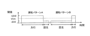
- FIG. 5 is a diagram showing threshold change processing executed by the reactive current control circuit 18 included in the controller 30 of the elevator control apparatus according to Embodiment 1 of the present invention. Specifically, the result of the threshold value changing process corresponding to the operation patterns A and B shown in FIG. 4 is shown.
- the controller 30 adds ⁇ Vd corresponding to the correction voltage component of the vertical short circuit prevention time Td to Vlim according to the above equation (1) during the power running operation.
- the threshold is dynamically changed and set.
- the controller 30 dynamically changes and sets the threshold value by subtracting ⁇ Vd from Vlim according to the above equation (2).
- FIG. 6 is a diagram showing a threshold value changing process different from FIG. 5 executed by the reactive current control circuit 18 included in the controller 30 of the elevator control apparatus according to Embodiment 1 of the present invention. It is. Specifically, in the threshold value changing process shown in FIG. 6, in addition to the process in FIG. 5, the threshold value is changed to a ramp function or a low-pass filter at the time of switching to further improve the control characteristics. I am trying.
- the threshold value can be prevented from being changed in a staircase pattern at a stroke, and the change amount of the threshold value per unit time can be limited to within the allowable value.
- the threshold value is switched smoothly, it is possible to suppress the occurrence of unpleasant vibrations in the car 35 and realize a smooth movement of the car.
- the first embodiment it is possible to provide a reactive current control circuit that realizes a control performance with higher accuracy than conventional in control of an elevator in which power running operation and regenerative operation are frequently switched. That is, a configuration is realized in which the switching timing between the power running operation / regenerative operation is predicted during the elevator traveling, and an appropriate reactive current command can be generated according to the operation state.
- the power running operation or the regenerative operation is specified by the load in the car and the traveling direction. Further, at the time of deceleration, the switching timing is predicted from the operation pattern information or the value of the active current command. In addition, when setting the power factor control threshold value for generating the reactive current command at the switching timing, the correction amount addition / subtraction is switched according to the value corresponding to the correction voltage component of the upper / lower short-circuit prevention time. .
- SiC is cited as an example of a high-speed switching device.
- a wide band gap semiconductor having a larger band gap than silicon other than SiC, for example, a gallium nitride material or diamond is used. is there.
- a bridge circuit composed of a self-extinguishing switch element and a diode formed of such a wide band gap semiconductor has a high withstand voltage and a high allowable current density. For this reason, it is possible to reduce the size of the bridge circuit. By using the reduced size of the bridge circuit, it is possible to reduce the size of the semiconductor module incorporating the bridge circuit.
- the heat sink fins can be downsized and the water cooling section can be air cooled, so that the semiconductor module can be further downsized.
- the switching frequency can be increased, the inductance capacity can also be reduced, and as an elevator control device, the AC reactor can be further reduced in size.
- both the self-extinguishing switch element and the diode be formed of a wide band gap semiconductor, but either the self-extinguishing switch element or the diode is formed of a wide band gap semiconductor. May be. Even in this case, the above-described effects can be obtained.
Landscapes
- Engineering & Computer Science (AREA)
- Power Engineering (AREA)
- Automation & Control Theory (AREA)
- Elevator Control (AREA)
- Inverter Devices (AREA)
- Rectifiers (AREA)
Abstract
L'invention porte sur un dispositif de commande d'ascenseur qui comporte : un convertisseur ; et un régulateur pour permettre de fournir une alimentation électrique en courant continu correspondant à une valeur cible à un moteur d'une machine de levage par exécution d'une commutation du convertisseur tout en commandant le facteur de puissance par division d'un composant de courant alternatif en un courant actif et un courant réactif. Lors de la génération d'une valeur d'instruction de courant réactif, le régulateur génère la valeur d'instruction de courant réactif de telle manière que : quand un ascenseur est dans une opération d'alimentation, une valeur de réglage d'opération d'alimentation qui rend la circulation d'un courant réactif plus difficile que quand l'ascenseur est dans une opération régénérative soit réglée à titre de valeur seuil ; et quand l'ascenseur est dans l'opération régénérative, une valeur de réglage d'opération régénérative qui rend la circulation d'un courant réactif plus facile que quand l'ascenseur est dans l'opération d'alimentation soit réglée à titre de valeur seuil.
Priority Applications (3)
| Application Number | Priority Date | Filing Date | Title |
|---|---|---|---|
| JP2018506656A JP6611909B2 (ja) | 2016-03-22 | 2016-03-22 | エレベータの制御装置およびエレベータの制御方法 |
| PCT/JP2016/058992 WO2017163312A1 (fr) | 2016-03-22 | 2016-03-22 | Dispositif de commande d'ascenseur et procédé de commande d'ascenseur |
| CN201680083523.4A CN109104893B (zh) | 2016-03-22 | 2016-03-22 | 电梯的控制装置和电梯的控制方法 |
Applications Claiming Priority (1)
| Application Number | Priority Date | Filing Date | Title |
|---|---|---|---|
| PCT/JP2016/058992 WO2017163312A1 (fr) | 2016-03-22 | 2016-03-22 | Dispositif de commande d'ascenseur et procédé de commande d'ascenseur |
Publications (1)
| Publication Number | Publication Date |
|---|---|
| WO2017163312A1 true WO2017163312A1 (fr) | 2017-09-28 |
Family
ID=59900099
Family Applications (1)
| Application Number | Title | Priority Date | Filing Date |
|---|---|---|---|
| PCT/JP2016/058992 Ceased WO2017163312A1 (fr) | 2016-03-22 | 2016-03-22 | Dispositif de commande d'ascenseur et procédé de commande d'ascenseur |
Country Status (3)
| Country | Link |
|---|---|
| JP (1) | JP6611909B2 (fr) |
| CN (1) | CN109104893B (fr) |
| WO (1) | WO2017163312A1 (fr) |
Citations (4)
| Publication number | Priority date | Publication date | Assignee | Title |
|---|---|---|---|---|
| JPS5882971A (ja) * | 1981-11-13 | 1983-05-18 | 株式会社日立製作所 | 直流エレベ−タ−の制御装置 |
| JPH04285472A (ja) * | 1991-03-15 | 1992-10-09 | Toshiba Corp | Pwmコンバ―タの制御方法及び装置 |
| JP2005073362A (ja) * | 2003-08-22 | 2005-03-17 | Rikogaku Shinkokai | 電力変換装置、モータドライブ装置、btbシステムおよび系統連系インバータシステム |
| JP2006223051A (ja) * | 2005-02-10 | 2006-08-24 | Mitsubishi Electric Corp | コンバータの制御方法及び装置、並びにその装置を用いた交流電動機の制御装置及びその交流電動機の制御装置を用いたエレベータの制御装置 |
Family Cites Families (3)
| Publication number | Priority date | Publication date | Assignee | Title |
|---|---|---|---|---|
| JP2004023934A (ja) * | 2002-06-19 | 2004-01-22 | Hitachi Ltd | 電源システム |
| JP5186586B2 (ja) * | 2011-09-01 | 2013-04-17 | 株式会社松井製作所 | 駆動制御装置、電気機器及び駆動制御方法 |
| JP5664588B2 (ja) * | 2012-04-20 | 2015-02-04 | 株式会社安川電機 | 電源回生装置および電力変換装置 |
-
2016
- 2016-03-22 WO PCT/JP2016/058992 patent/WO2017163312A1/fr not_active Ceased
- 2016-03-22 JP JP2018506656A patent/JP6611909B2/ja active Active
- 2016-03-22 CN CN201680083523.4A patent/CN109104893B/zh active Active
Patent Citations (4)
| Publication number | Priority date | Publication date | Assignee | Title |
|---|---|---|---|---|
| JPS5882971A (ja) * | 1981-11-13 | 1983-05-18 | 株式会社日立製作所 | 直流エレベ−タ−の制御装置 |
| JPH04285472A (ja) * | 1991-03-15 | 1992-10-09 | Toshiba Corp | Pwmコンバ―タの制御方法及び装置 |
| JP2005073362A (ja) * | 2003-08-22 | 2005-03-17 | Rikogaku Shinkokai | 電力変換装置、モータドライブ装置、btbシステムおよび系統連系インバータシステム |
| JP2006223051A (ja) * | 2005-02-10 | 2006-08-24 | Mitsubishi Electric Corp | コンバータの制御方法及び装置、並びにその装置を用いた交流電動機の制御装置及びその交流電動機の制御装置を用いたエレベータの制御装置 |
Also Published As
| Publication number | Publication date |
|---|---|
| JPWO2017163312A1 (ja) | 2018-12-20 |
| JP6611909B2 (ja) | 2019-11-27 |
| CN109104893B (zh) | 2020-06-23 |
| CN109104893A (zh) | 2018-12-28 |
Similar Documents
| Publication | Publication Date | Title |
|---|---|---|
| JP5363112B2 (ja) | エレベータ用の巻上モータを規格外の電源で連続的に駆動するシステムおよび方法 | |
| WO2007013448A1 (fr) | Ascenseur | |
| JP5307394B2 (ja) | エレベータの制御装置 | |
| JP6533548B2 (ja) | 乗客コンベア | |
| JP5404606B2 (ja) | エレベータの制御システム | |
| US7588125B2 (en) | Elevator control device | |
| JP4397721B2 (ja) | エレベータの制御装置 | |
| JP2009215012A (ja) | エレベータの非常時減速制御システム | |
| EP3083468B1 (fr) | Stratégie pwm pour un entraînement à récupération multiniveau | |
| CN102482049B (zh) | 电梯控制装置 | |
| JP6611909B2 (ja) | エレベータの制御装置およびエレベータの制御方法 | |
| JP6115644B2 (ja) | エレベータ制御装置 | |
| JP2016167966A (ja) | 負荷適応型ブースト電圧を供給するインバータ | |
| JP2010168139A (ja) | エレベーター制御装置 | |
| JP2014009041A (ja) | エレベーター制御装置 | |
| JP7184129B1 (ja) | エレベーターの制御装置及びエレベーターの制御方法 | |
| JP5095223B2 (ja) | エレベータ装置 | |
| HK1156014A1 (en) | Device of an method for speed control of elevator |
Legal Events
| Date | Code | Title | Description |
|---|---|---|---|
| WWE | Wipo information: entry into national phase |
Ref document number: 2018506656 Country of ref document: JP |
|
| 121 | Ep: the epo has been informed by wipo that ep was designated in this application |
Ref document number: 16895348 Country of ref document: EP Kind code of ref document: A1 |
|
| 122 | Ep: pct application non-entry in european phase |
Ref document number: 16895348 Country of ref document: EP Kind code of ref document: A1 |