WO2017163339A1 - Dispositif de climatisation - Google Patents
Dispositif de climatisation Download PDFInfo
- Publication number
- WO2017163339A1 WO2017163339A1 PCT/JP2016/059205 JP2016059205W WO2017163339A1 WO 2017163339 A1 WO2017163339 A1 WO 2017163339A1 JP 2016059205 W JP2016059205 W JP 2016059205W WO 2017163339 A1 WO2017163339 A1 WO 2017163339A1
- Authority
- WO
- WIPO (PCT)
- Prior art keywords
- heat exchanger
- temperature
- refrigerant
- refrigerant mixture
- azeotropic refrigerant
- Prior art date
- Legal status (The legal status is an assumption and is not a legal conclusion. Google has not performed a legal analysis and makes no representation as to the accuracy of the status listed.)
- Ceased
Links
Images








Classifications
-
- F—MECHANICAL ENGINEERING; LIGHTING; HEATING; WEAPONS; BLASTING
- F25—REFRIGERATION OR COOLING; COMBINED HEATING AND REFRIGERATION SYSTEMS; HEAT PUMP SYSTEMS; MANUFACTURE OR STORAGE OF ICE; LIQUEFACTION SOLIDIFICATION OF GASES
- F25B—REFRIGERATION MACHINES, PLANTS OR SYSTEMS; COMBINED HEATING AND REFRIGERATION SYSTEMS; HEAT PUMP SYSTEMS
- F25B1/00—Compression machines, plants or systems with non-reversible cycle
-
- C—CHEMISTRY; METALLURGY
- C09—DYES; PAINTS; POLISHES; NATURAL RESINS; ADHESIVES; COMPOSITIONS NOT OTHERWISE PROVIDED FOR; APPLICATIONS OF MATERIALS NOT OTHERWISE PROVIDED FOR
- C09K—MATERIALS FOR MISCELLANEOUS APPLICATIONS, NOT PROVIDED FOR ELSEWHERE
- C09K5/00—Heat-transfer, heat-exchange or heat-storage materials, e.g. refrigerants; Materials for the production of heat or cold by chemical reactions other than by combustion
- C09K5/02—Materials undergoing a change of physical state when used
- C09K5/04—Materials undergoing a change of physical state when used the change of state being from liquid to vapour or vice versa
-
- C—CHEMISTRY; METALLURGY
- C09—DYES; PAINTS; POLISHES; NATURAL RESINS; ADHESIVES; COMPOSITIONS NOT OTHERWISE PROVIDED FOR; APPLICATIONS OF MATERIALS NOT OTHERWISE PROVIDED FOR
- C09K—MATERIALS FOR MISCELLANEOUS APPLICATIONS, NOT PROVIDED FOR ELSEWHERE
- C09K5/00—Heat-transfer, heat-exchange or heat-storage materials, e.g. refrigerants; Materials for the production of heat or cold by chemical reactions other than by combustion
- C09K5/02—Materials undergoing a change of physical state when used
- C09K5/04—Materials undergoing a change of physical state when used the change of state being from liquid to vapour or vice versa
- C09K5/041—Materials undergoing a change of physical state when used the change of state being from liquid to vapour or vice versa for compression-type refrigeration systems
-
- C—CHEMISTRY; METALLURGY
- C09—DYES; PAINTS; POLISHES; NATURAL RESINS; ADHESIVES; COMPOSITIONS NOT OTHERWISE PROVIDED FOR; APPLICATIONS OF MATERIALS NOT OTHERWISE PROVIDED FOR
- C09K—MATERIALS FOR MISCELLANEOUS APPLICATIONS, NOT PROVIDED FOR ELSEWHERE
- C09K5/00—Heat-transfer, heat-exchange or heat-storage materials, e.g. refrigerants; Materials for the production of heat or cold by chemical reactions other than by combustion
- C09K5/02—Materials undergoing a change of physical state when used
- C09K5/04—Materials undergoing a change of physical state when used the change of state being from liquid to vapour or vice versa
- C09K5/041—Materials undergoing a change of physical state when used the change of state being from liquid to vapour or vice versa for compression-type refrigeration systems
- C09K5/044—Materials undergoing a change of physical state when used the change of state being from liquid to vapour or vice versa for compression-type refrigeration systems comprising halogenated compounds
- C09K5/045—Materials undergoing a change of physical state when used the change of state being from liquid to vapour or vice versa for compression-type refrigeration systems comprising halogenated compounds containing only fluorine as halogen
-
- F—MECHANICAL ENGINEERING; LIGHTING; HEATING; WEAPONS; BLASTING
- F24—HEATING; RANGES; VENTILATING
- F24F—AIR-CONDITIONING; AIR-HUMIDIFICATION; VENTILATION; USE OF AIR CURRENTS FOR SCREENING
- F24F11/00—Control or safety arrangements
- F24F11/30—Control or safety arrangements for purposes related to the operation of the system, e.g. for safety or monitoring
-
- F—MECHANICAL ENGINEERING; LIGHTING; HEATING; WEAPONS; BLASTING
- F24—HEATING; RANGES; VENTILATING
- F24F—AIR-CONDITIONING; AIR-HUMIDIFICATION; VENTILATION; USE OF AIR CURRENTS FOR SCREENING
- F24F11/00—Control or safety arrangements
- F24F11/70—Control systems characterised by their outputs; Constructional details thereof
-
- F—MECHANICAL ENGINEERING; LIGHTING; HEATING; WEAPONS; BLASTING
- F25—REFRIGERATION OR COOLING; COMBINED HEATING AND REFRIGERATION SYSTEMS; HEAT PUMP SYSTEMS; MANUFACTURE OR STORAGE OF ICE; LIQUEFACTION SOLIDIFICATION OF GASES
- F25B—REFRIGERATION MACHINES, PLANTS OR SYSTEMS; COMBINED HEATING AND REFRIGERATION SYSTEMS; HEAT PUMP SYSTEMS
- F25B1/00—Compression machines, plants or systems with non-reversible cycle
- F25B1/005—Compression machines, plants or systems with non-reversible cycle of the single unit type
-
- F—MECHANICAL ENGINEERING; LIGHTING; HEATING; WEAPONS; BLASTING
- F25—REFRIGERATION OR COOLING; COMBINED HEATING AND REFRIGERATION SYSTEMS; HEAT PUMP SYSTEMS; MANUFACTURE OR STORAGE OF ICE; LIQUEFACTION SOLIDIFICATION OF GASES
- F25B—REFRIGERATION MACHINES, PLANTS OR SYSTEMS; COMBINED HEATING AND REFRIGERATION SYSTEMS; HEAT PUMP SYSTEMS
- F25B13/00—Compression machines, plants or systems, with reversible cycle
-
- F—MECHANICAL ENGINEERING; LIGHTING; HEATING; WEAPONS; BLASTING
- F25—REFRIGERATION OR COOLING; COMBINED HEATING AND REFRIGERATION SYSTEMS; HEAT PUMP SYSTEMS; MANUFACTURE OR STORAGE OF ICE; LIQUEFACTION SOLIDIFICATION OF GASES
- F25B—REFRIGERATION MACHINES, PLANTS OR SYSTEMS; COMBINED HEATING AND REFRIGERATION SYSTEMS; HEAT PUMP SYSTEMS
- F25B41/00—Fluid-circulation arrangements
- F25B41/30—Expansion means; Dispositions thereof
- F25B41/37—Capillary tubes
-
- F—MECHANICAL ENGINEERING; LIGHTING; HEATING; WEAPONS; BLASTING
- F25—REFRIGERATION OR COOLING; COMBINED HEATING AND REFRIGERATION SYSTEMS; HEAT PUMP SYSTEMS; MANUFACTURE OR STORAGE OF ICE; LIQUEFACTION SOLIDIFICATION OF GASES
- F25B—REFRIGERATION MACHINES, PLANTS OR SYSTEMS; COMBINED HEATING AND REFRIGERATION SYSTEMS; HEAT PUMP SYSTEMS
- F25B49/00—Arrangement or mounting of control or safety devices
- F25B49/02—Arrangement or mounting of control or safety devices for compression type machines, plants or systems
-
- F—MECHANICAL ENGINEERING; LIGHTING; HEATING; WEAPONS; BLASTING
- F25—REFRIGERATION OR COOLING; COMBINED HEATING AND REFRIGERATION SYSTEMS; HEAT PUMP SYSTEMS; MANUFACTURE OR STORAGE OF ICE; LIQUEFACTION SOLIDIFICATION OF GASES
- F25B—REFRIGERATION MACHINES, PLANTS OR SYSTEMS; COMBINED HEATING AND REFRIGERATION SYSTEMS; HEAT PUMP SYSTEMS
- F25B49/00—Arrangement or mounting of control or safety devices
- F25B49/02—Arrangement or mounting of control or safety devices for compression type machines, plants or systems
- F25B49/022—Compressor control arrangements
-
- F—MECHANICAL ENGINEERING; LIGHTING; HEATING; WEAPONS; BLASTING
- F25—REFRIGERATION OR COOLING; COMBINED HEATING AND REFRIGERATION SYSTEMS; HEAT PUMP SYSTEMS; MANUFACTURE OR STORAGE OF ICE; LIQUEFACTION SOLIDIFICATION OF GASES
- F25B—REFRIGERATION MACHINES, PLANTS OR SYSTEMS; COMBINED HEATING AND REFRIGERATION SYSTEMS; HEAT PUMP SYSTEMS
- F25B9/00—Compression machines, plants or systems, in which the refrigerant is air or other gas of low boiling point
- F25B9/002—Compression machines, plants or systems, in which the refrigerant is air or other gas of low boiling point characterised by the refrigerant
-
- C—CHEMISTRY; METALLURGY
- C09—DYES; PAINTS; POLISHES; NATURAL RESINS; ADHESIVES; COMPOSITIONS NOT OTHERWISE PROVIDED FOR; APPLICATIONS OF MATERIALS NOT OTHERWISE PROVIDED FOR
- C09K—MATERIALS FOR MISCELLANEOUS APPLICATIONS, NOT PROVIDED FOR ELSEWHERE
- C09K2205/00—Aspects relating to compounds used in compression type refrigeration systems
- C09K2205/10—Components
- C09K2205/12—Hydrocarbons
- C09K2205/126—Unsaturated fluorinated hydrocarbons
-
- C—CHEMISTRY; METALLURGY
- C09—DYES; PAINTS; POLISHES; NATURAL RESINS; ADHESIVES; COMPOSITIONS NOT OTHERWISE PROVIDED FOR; APPLICATIONS OF MATERIALS NOT OTHERWISE PROVIDED FOR
- C09K—MATERIALS FOR MISCELLANEOUS APPLICATIONS, NOT PROVIDED FOR ELSEWHERE
- C09K2205/00—Aspects relating to compounds used in compression type refrigeration systems
- C09K2205/34—The mixture being non-azeotropic
-
- F—MECHANICAL ENGINEERING; LIGHTING; HEATING; WEAPONS; BLASTING
- F24—HEATING; RANGES; VENTILATING
- F24F—AIR-CONDITIONING; AIR-HUMIDIFICATION; VENTILATION; USE OF AIR CURRENTS FOR SCREENING
- F24F2140/00—Control inputs relating to system states
- F24F2140/20—Heat-exchange fluid temperature
-
- F—MECHANICAL ENGINEERING; LIGHTING; HEATING; WEAPONS; BLASTING
- F25—REFRIGERATION OR COOLING; COMBINED HEATING AND REFRIGERATION SYSTEMS; HEAT PUMP SYSTEMS; MANUFACTURE OR STORAGE OF ICE; LIQUEFACTION SOLIDIFICATION OF GASES
- F25B—REFRIGERATION MACHINES, PLANTS OR SYSTEMS; COMBINED HEATING AND REFRIGERATION SYSTEMS; HEAT PUMP SYSTEMS
- F25B2400/00—Component parts or details not otherwise provided for in this subclass
- F25B2400/04—Refrigeration circuit bypassing means
- F25B2400/0405—Refrigeration circuit bypassing means for desuperheaters
-
- F—MECHANICAL ENGINEERING; LIGHTING; HEATING; WEAPONS; BLASTING
- F25—REFRIGERATION OR COOLING; COMBINED HEATING AND REFRIGERATION SYSTEMS; HEAT PUMP SYSTEMS; MANUFACTURE OR STORAGE OF ICE; LIQUEFACTION SOLIDIFICATION OF GASES
- F25B—REFRIGERATION MACHINES, PLANTS OR SYSTEMS; COMBINED HEATING AND REFRIGERATION SYSTEMS; HEAT PUMP SYSTEMS
- F25B2400/00—Component parts or details not otherwise provided for in this subclass
- F25B2400/13—Economisers
-
- F—MECHANICAL ENGINEERING; LIGHTING; HEATING; WEAPONS; BLASTING
- F25—REFRIGERATION OR COOLING; COMBINED HEATING AND REFRIGERATION SYSTEMS; HEAT PUMP SYSTEMS; MANUFACTURE OR STORAGE OF ICE; LIQUEFACTION SOLIDIFICATION OF GASES
- F25B—REFRIGERATION MACHINES, PLANTS OR SYSTEMS; COMBINED HEATING AND REFRIGERATION SYSTEMS; HEAT PUMP SYSTEMS
- F25B2600/00—Control issues
- F25B2600/02—Compressor control
- F25B2600/025—Compressor control by controlling speed
-
- F—MECHANICAL ENGINEERING; LIGHTING; HEATING; WEAPONS; BLASTING
- F25—REFRIGERATION OR COOLING; COMBINED HEATING AND REFRIGERATION SYSTEMS; HEAT PUMP SYSTEMS; MANUFACTURE OR STORAGE OF ICE; LIQUEFACTION SOLIDIFICATION OF GASES
- F25B—REFRIGERATION MACHINES, PLANTS OR SYSTEMS; COMBINED HEATING AND REFRIGERATION SYSTEMS; HEAT PUMP SYSTEMS
- F25B2600/00—Control issues
- F25B2600/25—Control of valves
- F25B2600/2501—Bypass valves
-
- F—MECHANICAL ENGINEERING; LIGHTING; HEATING; WEAPONS; BLASTING
- F25—REFRIGERATION OR COOLING; COMBINED HEATING AND REFRIGERATION SYSTEMS; HEAT PUMP SYSTEMS; MANUFACTURE OR STORAGE OF ICE; LIQUEFACTION SOLIDIFICATION OF GASES
- F25B—REFRIGERATION MACHINES, PLANTS OR SYSTEMS; COMBINED HEATING AND REFRIGERATION SYSTEMS; HEAT PUMP SYSTEMS
- F25B2600/00—Control issues
- F25B2600/25—Control of valves
- F25B2600/2509—Economiser valves
-
- F—MECHANICAL ENGINEERING; LIGHTING; HEATING; WEAPONS; BLASTING
- F25—REFRIGERATION OR COOLING; COMBINED HEATING AND REFRIGERATION SYSTEMS; HEAT PUMP SYSTEMS; MANUFACTURE OR STORAGE OF ICE; LIQUEFACTION SOLIDIFICATION OF GASES
- F25B—REFRIGERATION MACHINES, PLANTS OR SYSTEMS; COMBINED HEATING AND REFRIGERATION SYSTEMS; HEAT PUMP SYSTEMS
- F25B2700/00—Sensing or detecting of parameters; Sensors therefor
- F25B2700/21—Temperatures
- F25B2700/2101—Temperatures in a bypass
-
- F—MECHANICAL ENGINEERING; LIGHTING; HEATING; WEAPONS; BLASTING
- F25—REFRIGERATION OR COOLING; COMBINED HEATING AND REFRIGERATION SYSTEMS; HEAT PUMP SYSTEMS; MANUFACTURE OR STORAGE OF ICE; LIQUEFACTION SOLIDIFICATION OF GASES
- F25B—REFRIGERATION MACHINES, PLANTS OR SYSTEMS; COMBINED HEATING AND REFRIGERATION SYSTEMS; HEAT PUMP SYSTEMS
- F25B2700/00—Sensing or detecting of parameters; Sensors therefor
- F25B2700/21—Temperatures
- F25B2700/2103—Temperatures near a heat exchanger
-
- F—MECHANICAL ENGINEERING; LIGHTING; HEATING; WEAPONS; BLASTING
- F25—REFRIGERATION OR COOLING; COMBINED HEATING AND REFRIGERATION SYSTEMS; HEAT PUMP SYSTEMS; MANUFACTURE OR STORAGE OF ICE; LIQUEFACTION SOLIDIFICATION OF GASES
- F25B—REFRIGERATION MACHINES, PLANTS OR SYSTEMS; COMBINED HEATING AND REFRIGERATION SYSTEMS; HEAT PUMP SYSTEMS
- F25B2700/00—Sensing or detecting of parameters; Sensors therefor
- F25B2700/21—Temperatures
- F25B2700/2117—Temperatures of an evaporator
- F25B2700/21174—Temperatures of an evaporator of the refrigerant at the inlet of the evaporator
-
- F—MECHANICAL ENGINEERING; LIGHTING; HEATING; WEAPONS; BLASTING
- F25—REFRIGERATION OR COOLING; COMBINED HEATING AND REFRIGERATION SYSTEMS; HEAT PUMP SYSTEMS; MANUFACTURE OR STORAGE OF ICE; LIQUEFACTION SOLIDIFICATION OF GASES
- F25B—REFRIGERATION MACHINES, PLANTS OR SYSTEMS; COMBINED HEATING AND REFRIGERATION SYSTEMS; HEAT PUMP SYSTEMS
- F25B2700/00—Sensing or detecting of parameters; Sensors therefor
- F25B2700/21—Temperatures
- F25B2700/2117—Temperatures of an evaporator
- F25B2700/21175—Temperatures of an evaporator of the refrigerant at the outlet of the evaporator
Definitions
- the present invention relates to an air conditioner, and more particularly to an air conditioner using a non-azeotropic refrigerant mixture.
- a mixed refrigerant in which GWP is lowered by mixing a refrigerant composed of a single component with another refrigerant having a lower global warming potential (GWP). May be used.
- Patent Document 1 detects a refrigerant state in a refrigerant circuit when the operation is stopped in a refrigeration apparatus having a refrigerant circuit using a non-azeotropic refrigerant mixture including refrigerants having different boiling points.
- Patent Document 1 detects a refrigerant state in a refrigerant circuit when the operation is stopped in a refrigeration apparatus having a refrigerant circuit using a non-azeotropic refrigerant mixture including refrigerants having different boiling points.
- a configuration for detecting refrigerant leakage is disclosed.
- the refrigerant used in the air conditioner may leak from, for example, a pipe connection.
- a refrigerant having a lower boiling point hereinafter, also referred to as a “low-boiling refrigerant” among the refrigerants included in the non-azeotropic refrigerant mixture is more likely to be vaporized and is likely to leak. . Therefore, the composition ratio of the non-azeotropic mixed refrigerant can change with the passage of time after the non-azeotropic mixed refrigerant is filled in the air conditioner.
- the composition ratio of the non-azeotropic refrigerant mixture changes, the characteristics of the non-azeotropic refrigerant mixture can change. Therefore, for example, it may be difficult to continue the optimum superheat degree control. If the air conditioner is continuously operated in such a state, sufficient air conditioning capability cannot be obtained, and the possibility that the air conditioner will break down increases. Therefore, it is necessary to detect a change in the composition ratio of the non-azeotropic refrigerant mixture.
- Patent Document 1 Japanese Patent Application Laid-Open No. 8-54161
- Patent Document 2 by utilizing the fact that the temperature, pressure, and amount of refrigerant leakage in the refrigerant circuit have a predetermined relationship, refrigerant leakage is measured from the measured temperature and pressure.
- a configuration for detection is disclosed.
- Patent Document 1 Japanese Patent Laid-Open No. 8-54161
- the present invention has been made to solve the above-described problems, and an object of the present invention is to provide an air conditioner capable of detecting a change in the composition ratio of a non-azeotropic refrigerant mixture while suppressing manufacturing costs. Is to provide.
- An air conditioner includes a non-azeotropic refrigerant mixture including a first refrigerant and a second refrigerant having a boiling point higher than that of the first refrigerant, a compressor, a first heat exchanger, a second heat exchanger, It is comprised so that it may circulate in the 1st circulation direction of the order of 1 expansion valve and a 3rd heat exchanger.
- the air conditioner includes a first bypass channel, a second bypass channel, and a notification unit.
- the first bypass flow path branches from the first flow path connecting the second heat exchanger and the first expansion valve, and passes through the first pressure reducer and the second heat exchanger in this order to suck the compressor. Connected to the second flow path connected to the mouth.
- the second bypass flow path branches off from the third flow path connecting the first heat exchanger and the second heat exchanger, passes through the second pressure reducer, and passes through the first pressure reducer and the second heat exchanger.
- the notification unit warns the user when the ratio of the first refrigerant determined from the first difference between the first temperature and the second temperature and the second difference between the third temperature and the fourth temperature is different from the appropriate value. It is comprised so that it may alert
- the first temperature is the temperature of the non-azeotropic refrigerant mixture between the first heat exchanger and the second heat exchanger.
- the second temperature is the temperature of the non-azeotropic refrigerant mixture between the second heat exchanger and the first expansion valve.
- the third temperature is the temperature of the non-azeotropic refrigerant mixture between the first pressure reducer and the first connection point.
- the fourth temperature is the temperature of the non-azeotropic refrigerant mixture between the second pressure reducer and the first connection point.
- the ratio of the low boiling point refrigerant can be determined from the difference in temperature, a pressure sensor is not necessary for determining the ratio. As a result, it is possible to detect a change in the composition ratio of the non-azeotropic refrigerant mixture while suppressing the manufacturing cost.
- FIG. 5 is a Ph diagram showing the relationship between pressure and enthalpy for a single refrigerant and a non-azeotropic refrigerant mixture. It is a flowchart for demonstrating the process of superheat degree control. It is a figure which shows the correspondence of the absolute value of a temperature difference, and the ratio of the low boiling point refrigerant
- FIG. 3 is a Ph diagram showing the relationship between the pressure of the non-azeotropic refrigerant mixture and enthalpy in Embodiment 1. 3 is a flowchart for illustrating superheat degree control performed in the first embodiment.
- 6 is a functional block diagram illustrating a configuration of an air conditioner according to a modification of the first embodiment. It is a flowchart for demonstrating the process which controls an expansion valve.
- 6 is a functional block diagram illustrating a configuration during cooling operation of an air-conditioning apparatus according to Embodiment 2.
- FIG. It is a functional block diagram which shows the structure at the time of the heating operation of the air conditioning apparatus which concerns on Embodiment 2.
- FIG. FIG. 6 is a Ph diagram showing the relationship between the pressure of a non-azeotropic refrigerant mixture and enthalpy in the air-conditioning apparatus according to Embodiment 2.
- 5 is a flowchart for illustrating superheat degree control performed in a second embodiment.
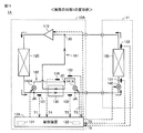
- FIG. 1 is a functional block diagram showing the configuration of the air-conditioning apparatus 1 according to Embodiment 1. As shown in FIG. 1, the air conditioner 1 includes an outdoor unit 10 and an indoor unit 11.
- the outdoor unit 10 includes a compressor 110, a first heat exchanger 120, a second heat exchanger 130, a first bypass passage 161, a capillary 141, a second bypass passage 162, a capillary 142, A control device 12 and a notification unit 13 are included.
- the indoor unit 11 includes an expansion valve 140 and a third heat exchanger 150.
- the control device 12 may be included in the indoor unit 11, or may not be included in either the outdoor unit 10 or the indoor unit 11.
- the refrigerant circulates in the order of the compressor 110, the first heat exchanger 120, the second heat exchanger 130, the expansion valve 140, and the third heat exchanger 150.
- the first heat exchanger 120 functions as a condenser.
- the second heat exchanger 130 connected between the first heat exchanger 120 and the expansion valve 140 cools the liquid refrigerant (liquid refrigerant) from the first heat exchanger 120.
- the third heat exchanger 150 receives the liquid refrigerant from the second heat exchanger 130 and functions as an evaporator.
- the air conditioner 1 performs cooling by absorbing heat from room air by the third heat exchanger 150.
- the compressor 110 is controlled in its drive frequency f by the control device 12 to control its capacity (the amount of refrigerant discharged per unit time).
- the compressor 110 receives a gaseous refrigerant (gas refrigerant) from the third heat exchanger 150, compresses it, and outputs it.
- the gas refrigerant discharged from the compressor 110 is condensed and a liquid refrigerant is output.
- the first heat exchanger 120 releases heat (condensation heat) to the outside when the gas refrigerant condenses.
- the first bypass channel 161 branches off from a connection point JA between the second heat exchanger 130 and the expansion valve 140.
- the first bypass flow path 161 connects the flow path connected to the suction port of the compressor 110, that is, the third heat exchanger 150 and the compressor 110 via the capillary 141 and the second heat exchanger 130 in this order. Connected to the flow path.
- the liquid refrigerant from the connection point JA is decompressed in a heat-insulating state by the capillary 141, and a part of the liquid refrigerant boils at a low temperature.
- the refrigerant from the capillary 141 is a gas-liquid two-phase refrigerant (wet vapor).
- the second heat exchanger 130 increases the supercooling degree of the liquid refrigerant by absorbing the heat of the liquid refrigerant from the first heat exchanger 120 into the wet steam from the capillary 141.
- the pipe through which the liquid refrigerant from the first heat exchanger 120 and the pipe through which the wet steam from the capillary flow are substantially parallel to each other, and from the first heat exchanger 120
- the liquid refrigerant is arranged so that the flow of the liquid refrigerant is opposite to the flow of the wet steam from the capillary. That is, both the pipes are arranged such that the flow of the liquid refrigerant from the first heat exchanger 120 and the flow of the wet steam from the capillary 141 are opposed to each other.
- the second heat exchanger 130 is, for example, a double tube heat exchanger.
- the second heat exchanger 130 corresponds to the third heat exchanger of the present invention.
- the expansion valve 140 adiabatically expands the liquid refrigerant from the second heat exchanger 130 to reduce the pressure.
- the opening degree of the expansion valve 140 is adjusted by the control device 12. Wet steam is output from the expansion valve 140.
- the expansion valve 140 is, for example, an electronically controlled expansion valve (LEV: Linear Expansion Valve).
- the third heat exchanger 150 evaporates the liquid refrigerant contained in the wet steam from the expansion valve 140.
- a gas refrigerant is output from the third heat exchanger 150.
- the liquid refrigerant evaporates by taking heat (evaporation heat) from the indoor air.
- the second bypass flow path 162 branches off from a connection point JB between the first heat exchanger 120 and the second heat exchanger 130.
- the second bypass flow path 162 is connected to the connection point JC between the capillary 141 and the second heat exchanger 130 via the capillary 142.
- a part of the liquid refrigerant from the connection point JB is boiled at a low temperature by being decompressed by the capillary 142 in an adiabatic state.
- the refrigerant from the capillary 142 is wet steam, and merges with the wet steam from the capillary 141 at the connection point JC.
- the refrigerant from the connection point JC merges with the refrigerant from the third heat exchanger 150 at the connection point JD between the third heat exchanger 150 and the compressor 110, and is sucked into the compressor 110.
- the temperature sensor 131 measures the temperature T1 of the refrigerant flowing between the connection point JB and the second heat exchanger 130.
- the temperature sensor 132 measures the temperature T2 of the refrigerant flowing between the second heat exchanger 130 and the connection point JA.
- the temperature sensor 133 measures the temperature T3 of the refrigerant flowing between the capillary 141 and the connection point JC.
- the temperature sensor 134 measures the temperature T4 of the refrigerant flowing between the capillary 142 and the connection point JC.
- the temperature sensor 151 measures the temperature T5 of the refrigerant flowing between the expansion valve 140 and the third heat exchanger 150.
- the temperature sensor 152 measures the temperature T6 of the refrigerant flowing between the third heat exchanger 150 and the compressor 110.
- the temperature sensors 131 to 134, 151, and 152 are, for example, thermistors.
- the control device 12 includes a control unit 121 and a storage unit 122.
- the control unit 121 includes a computer such as a CPU (Central Processing Unit).
- the storage unit 122 includes a nonvolatile memory such as a flash memory.
- the storage unit 122 is, for example, an OS (Operating System) that is read and executed by the control unit 121, various application programs (for example, a program for controlling the degree of superheat), and various data (for example, Data on the characteristics of the refrigerant, such as isotherms, saturated liquid lines and saturated vapor lines).
- OS Operating System
- the control device 12 receives signals from the temperature sensors 131 to 134, 151, and 152, and sets the target superheat degree of the refrigerant output from the first heat exchanger 120.
- the control device 12 adjusts the opening degree of the expansion valve 140 so that the superheat degree of the refrigerant flowing between the first heat exchanger 120 and the compressor 110 approaches the target superheat degree (superheat degree control).
- reports the warning containing the content instruct
- the contents of the notification are, for example, that a refrigerant leak has occurred, that the refrigerant has been misfilled, or that it is a maintenance time.
- the notification unit 13 includes, for example, a speaker capable of outputting a message, a monitor capable of displaying a message, a lamp, and a communication device capable of transmitting a message.
- Examples of the refrigerant used in the air conditioner 1 include a non-azeotropic refrigerant mixture including R32 as a low boiling point refrigerant and R1234yf as another refrigerant.
- the non-azeotropic refrigerant mixture used in the air conditioner 1 may include R1123 or R1234ze in order to lower the GWP value.
- the non-azeotropic refrigerant mixture used in the air conditioning apparatus 1 may include three or more types of refrigerants. Below, the case where a low boiling-point refrigerant
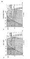
- FIG. 2 is a Ph diagram (a) of a single refrigerant and a Ph diagram (b) of a non-azeotropic refrigerant mixture.
- a curve LC is a saturated liquid line of a single refrigerant.
- a curve GC is a saturated vapor line of a single refrigerant.
- Point CP is the critical point of a single refrigerant.
- Curves IA, IB, and IC are isotherms at temperatures TA, TB, and TC (TA ⁇ TB ⁇ TC), respectively.
- the curve LC1 is a saturated liquid line of a non-azeotropic refrigerant mixture.
- a curve GC1 is a saturated vapor line of the non-azeotropic refrigerant mixture.
- Point CP1 is a critical point of the non-azeotropic refrigerant mixture.
- Curves IA1, IB1, and IC1 are isotherms of temperatures TA, TB, and TC, respectively.
- the critical point is a point indicating a limit of a range in which a phase change can occur between the liquid refrigerant and the gas refrigerant, and is an intersection of the saturated liquid line and the saturated vapor line.
- the refrigerant pressure becomes higher than the pressure at the critical point, no phase change occurs between the liquid refrigerant and the gas refrigerant.
- the refrigerant In the region where the enthalpy is lower than the saturated liquid line, the refrigerant is a liquid. In the region sandwiched between the saturated liquid line and the saturated vapor line, the refrigerant is in a gas-liquid two-phase state (wet steam). In the region where the enthalpy is higher than the saturated vapor line, the refrigerant is a gas.
- the pressure of the isotherm decreases as the enthalpy increases in the wet steam region.
- the dotted line indicating the pressure P1 intersects with the isotherm in the order of the isotherm IA1 (temperature TA), IB1 (temperature TB), and IC1 (temperature TC) as the enthalpy increases. Since TA ⁇ TB ⁇ TC, when the pressure is substantially constant, the temperature of the wet vapor of the non-azeotropic refrigerant mixture increases as the enthalpy increases.
- the temperature difference between the point on the saturated liquid line and the point on the saturated vapor line at the same pressure is referred to as a temperature gradient.
- the temperature difference between the point SL1 on the saturated liquid line LC1 and the point SG1 on the saturated vapor line GC1 is a temperature gradient.
- the refrigerant used in the air conditioner 1 may leak from, for example, a pipe connection.
- a non-azeotropic refrigerant mixture including a plurality of types of refrigerants a low-boiling refrigerant is easier to vaporize, and therefore, is more likely to leak than other refrigerants constituting the non-azeotropic refrigerant mixture. Therefore, the composition ratio of the non-azeotropic refrigerant mixture may change with the passage of time after the non-azeotropic refrigerant mixture is filled in the air conditioner 1.
- FIG. 3 is a flowchart for explaining the superheat degree control process performed by the control device 12.
- the controller 12 receives the temperatures T5 and T6 from the temperature sensors 151 and 152 in step (hereinafter, simply referred to as “S”) S10, and outputs them from the third heat exchanger 150.
- the target superheat degree of the non-azeotropic refrigerant mixture is set, and the process proceeds to step S20.
- the control device 12 adjusts the opening degree of the expansion valve 140 so that the superheat degree of the non-azeotropic refrigerant mixture at the time when the evaporation process is finished approaches the target superheat degree, and ends the process.
- the composition ratio of the non-azeotropic refrigerant mixture changes, the characteristics of the non-azeotropic refrigerant mixture, such as the temperature gradient, change. For this reason, for example, the optimum superheat degree of the non-azeotropic refrigerant mixture at the time when the evaporation process is completed changes, and it is difficult to continue the optimum superheat degree control unless the target superheat degree is reset. If the air conditioner 1 is continuously operated in such a state, sufficient air conditioning capability cannot be obtained, and the possibility that the air conditioner 1 breaks down increases. Therefore, when the change in the composition ratio of the non-azeotropic refrigerant mixed in the air conditioner 1 changes, it is necessary to reset the target superheat degree.
- the temperature and pressure of the non-azeotropic refrigerant mixture are measured, and the leakage of the low-boiling refrigerant is determined from the relationship between the temperature, pressure, and the amount of leakage of the low-boiling refrigerant.
- a method for calculating for example, the temperature and pressure of the non-azeotropic refrigerant mixture are measured, and the leakage of the low-boiling refrigerant is determined from the relationship between the temperature, pressure, and the amount of leakage of the low-boiling refrigerant.
- the pressure sensor necessary for measuring the pressure is often larger and more expensive than the temperature sensor. According to the above method, since a pressure sensor is required, it may be difficult to suppress the manufacturing cost of the air conditioner 1.
- the ratio of the low boiling point refrigerant is calculated by utilizing the fact that the temperature gradient of the non-azeotropic refrigerant mixture changes when the ratio of the low boiling point refrigerant changes. Specifically, the ratio of the low boiling point refrigerant is calculated from the correspondence relationship between the difference between the temperatures T1 and T2, the difference between the temperatures T3 and T4, and the ratio of the low boiling point refrigerant of the non-azeotropic refrigerant mixture. Since it is temperature that needs to be measured in order to calculate the ratio of the low-boiling refrigerant, a pressure sensor is not necessary for calculating the ratio of the low-boiling refrigerant. As a result, according to Embodiment 1, a change in the composition ratio of the non-azeotropic refrigerant mixture can be detected, and the manufacturing cost of the air conditioner 1 can be suppressed.
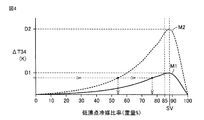
- FIG. 4 is a diagram showing a correspondence relationship between the absolute value ⁇ T12 of the difference between the temperatures T1 and T2, the absolute value ⁇ T34 of the difference between the temperatures T3 and T4, and the ratio of the low boiling point refrigerant in the non-azeotropic refrigerant mixture.
- a curve M1 is a diagram illustrating a correspondence relationship between the absolute value ⁇ T34 and the ratio of the low boiling point refrigerant when the absolute value ⁇ T12 is 10K.
- a curve M2 is a diagram illustrating a correspondence relationship between the absolute value ⁇ T34 and the ratio of the low boiling point refrigerant when the absolute value ⁇ T12 is 20K. The correspondence relationship between the absolute values ⁇ T12 and ⁇ T34 shown in FIG.
- FIG. 4 shows the corresponding relationship when the absolute value ⁇ T12 is 10K and 20K, the corresponding relationship when the absolute value ⁇ T12 is another value can be calculated in the same manner.
- the absolute value ⁇ T34 when the absolute value ⁇ T12 is 10K and 20K, the absolute value ⁇ T34 is maximum in the range of the low boiling point refrigerant ratio of 85% to 90% in any case.
- the maximum value D2 of the absolute value ⁇ T34 when the absolute value ⁇ T12 is 20K is larger than the maximum value D1 of the absolute value ⁇ T34 when the absolute value ⁇ T12 is 10K.
- the range in which the absolute value ⁇ T34 changes is larger when the absolute value ⁇ T12 is 20K.
- the range in which the absolute value ⁇ T34 changes tends to increase.
- the ratio of the low boiling point refrigerant can be calculated.
- the absolute value ⁇ T12 is determined by setting the ratio of the low-boiling refrigerant to a reference ratio SV or less (for example, 85% in FIG. 5) where ⁇ T34 is maximum, if the absolute value ⁇ T34 increases, The ratio also increases monotonously. Therefore, when the ratio of the low boiling point refrigerant is smaller than the reference ratio, when the absolute values ⁇ T12 and ⁇ T34 are determined, the ratio of the low boiling point refrigerant is also uniquely determined.
- the ratio of the low boiling point refrigerant in the non-azeotropic refrigerant mixture charged into the air conditioner 1 is made simpler. be able to.
- the upper limit of the low boiling point refrigerant in the non-azeotropic refrigerant mixture charged in the air conditioner 1 is not limited to 85%, and can be appropriately calculated by actual machine experiments or simulations.
- FIG. 5 is a Ph diagram showing the relationship between the pressure of the non-azeotropic refrigerant mixture and enthalpy in the air conditioner 1 of FIG.
- the circulation of the non-azeotropic refrigerant mixture in the air conditioner 1 is represented as a cycle C1 that returns from the point R11 to the point R11 via the point R12, the point R13, the point R14, and the point R15.
- the state change from the point R11 to the point R12 represents the process of compression of the non-azeotropic refrigerant mixture by the compressor 110.
- the state change from the point R12 to the point R13 represents the process of refrigerant condensation by the first heat exchanger 120.
- the state change from the point R13 to the point R14 represents a process of cooling the non-azeotropic refrigerant mixture by the second heat exchanger 130.
- the state change from the point R14 to the point R15 represents the process of adiabatic expansion of the non-azeotropic refrigerant mixture by the expansion valve 140.
- the state change from the point R15 to the point R11 represents the process of evaporation of the non-azeotropic refrigerant mixture by the third heat exchanger 150.
- the non-azeotropic refrigerant mixture flowing between the expansion valve 140 and the third heat exchanger 150 is the starting point of the evaporation process by the third heat exchanger 150 at the point R15 in FIG. Is in a state.
- the non-azeotropic refrigerant mixture flowing between the third heat exchanger 150 and the compressor 110 is in a state of a point R11 in FIG. 5 which is an end point of the evaporation process by the third heat exchanger 150.
- the non-azeotropic refrigerant mixture flowing between the connection point JB and the second heat exchanger 130 is the one before cooling by the second heat exchanger 130, it is in a state of a point R13 in FIG.
- the non-azeotropic refrigerant mixture that flows between the capillary 142 and the connection point JC is a non-azeotropic refrigerant mixture in the state of the point R13 that is decompressed by the capillary 141 in an adiabatic state.
- the enthalpy is almost equal to the enthalpy at point R13 in FIG.
- the capillary 141 is connected to a flow path between the third heat exchanger 150 and the compressor 110 via the second bypass flow path 162 and the first bypass flow path 161.
- the pressure of the non-azeotropic refrigerant mixture flowing between the capillary 141 and the connection point JC is substantially equal to the pressure at the point R11 corresponding to the refrigerant state between the third heat exchanger 150 and the compressor 110.
- the pressure during the evaporation process by the third heat exchanger 150 is substantially constant.
- the non-azeotropic refrigerant mixture flowing between the capillary 141 and the connection point JC is in a state of a point R16 where the enthalpy is substantially equal to the point R13 in the evaporation process by the third heat exchanger 150.
- the non-azeotropic refrigerant mixture flowing between the second heat exchanger 130 and the connection point JA is after cooling by the second heat exchanger 130, it is in a state of a point R14 in FIG.
- the non-azeotropic refrigerant mixture flowing between the capillary 141 and the connection point JC is a non-azeotropic refrigerant mixture in the state of the point R14 decompressed by the capillary 142 in an adiabatic state.
- the enthalpy is approximately equal to the enthalpy at point R14.
- the enthalpy of the point R14 is substantially equal to the enthalpy of the state of the point R15 obtained by adiabatically expanding the state of the point R14.
- the capillary 142 is connected to a flow path between the third heat exchanger 150 and the compressor 110 via the first bypass flow path 161.
- the pressure of the non-azeotropic refrigerant mixture flowing between the capillary 142 and the connection point JC is the pressure at the point R11 corresponding to the state of the non-azeotropic refrigerant mixture between the third heat exchanger 150 and the compressor 110. Almost equal.
- Point R11 is the end point of the evaporation process by the third heat exchanger 150.
- the pressure of the evaporation process is almost constant.
- the pressure at point R11 is substantially equal to the pressure at point R15, which is the starting point of the evaporation process.
- the enthalpy at point R15 is approximately equal to the enthalpy at point R14. It can be said that the non-azeotropic refrigerant mixture flowing between the capillary 142 and the connection point JC is in a state of a point R15 in FIG.
- the absolute value ⁇ T12 of the difference between the temperatures T1 and T2 the absolute value ⁇ T34 of the difference between the temperatures T3 and T4, and the ratio of the low boiling point refrigerant are in a predetermined relationship (see FIG. 4).
- the ratio of the low boiling point refrigerant is calculated from the absolute value ⁇ T12 and the absolute value ⁇ T34.
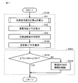
- FIG. 6 is a flowchart for illustrating superheat degree control performed in control device 12 of FIG. The processing shown in FIG. 6 is performed periodically or when a predetermined event occurs by a main routine (not shown) performed by the control device 12 for controlling the air conditioner 1.
- S10 in FIG. 3 includes S11 to S14 in FIG.
- S20 in FIG. 3 includes S21 and S22 in FIG.
- the control device 12 calculates the ratio wt of the low boiling point refrigerant in S11, and advances the process to S12.
- the control device 12 calculates the temperature gradient ⁇ TG at the pressure in the evaporation process from the ratio wt of the low boiling point refrigerant, and advances the process to S13.
- the temperature gradient ⁇ TG is the difference between the temperature at point SG1 and the temperature at point SL1 in FIG.
- control device 12 sets target superheat degree SH from temperatures T5 and T6 in S13, and advances the process to S14.
- the controller 12 determines whether or not the temperature difference ⁇ T65 is equal to the sum of the temperature gradient ⁇ TG and the target superheat degree SH in S21.
- S21 when the absolute value of the difference between the temperature difference ⁇ T65 and the sum of the temperature gradient ⁇ TG and the target superheat degree SH is smaller than the threshold, the temperature difference ⁇ T65 and the sum of the temperature gradient ⁇ TG and the target superheat degree SH are equal. You may judge.
- control device 12 advances the process to S22.
- the control device 12 controls the opening degree of the expansion valve 140 so that the temperature difference ⁇ T65 becomes equal to the sum of the temperature gradient ⁇ TG and the target superheat degree SH, and then returns the process to the main routine.
- control device 12 returns the process to the main routine.
- the optimum target superheat degree at the timing can be set. As a result, optimal superheat degree control can be continued.
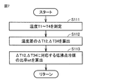
- FIG. 7 is a flowchart for explaining the low boiling point refrigerant ratio calculation process performed in S11 of FIG.
- the processing shown in FIG. 7 is performed as necessary by a main routine (not shown) performed by the control device 12 for controlling the air conditioner 1 or a subroutine (not shown) called from the main routine.
- the control device 12 measures temperatures T1 to T4 (see FIG. 1) in S111, and advances the process to S112.
- ) and ⁇ T34 (
- the control device 12 calculates the low boiling point refrigerant ratio wt corresponding to the absolute values ⁇ T12 and ⁇ T34 using the relationship between the absolute values ⁇ T12 and ⁇ T34 and the low boiling point refrigerant ratio wt (see FIG. 4). To the main routine or subroutine.
- the ratio wt of the low boiling point refrigerant can be calculated using the temperature sensor without using the pressure sensor.
- the low boiling point refrigerant ratio calculation process is performed.
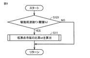
- the reference frequency fs1 is determined according to the resolution of the temperature sensors 133 and 134. That is, when the drive frequency f is lower than the reference frequency fs1, the range in which the absolute value ⁇ T34 changes becomes small, and the change in the ratio wt of the low boiling point refrigerant is captured as the change in the absolute value ⁇ T34 with the resolution of the temperature sensors 133 and 134. Can be difficult.
- FIG. 8 is a flowchart for explaining a process for calculating the ratio of the low boiling point refrigerant according to the drive frequency f of the compressor 110, which is performed in the control device 12 of FIG.
- the processing shown in FIG. 8 is performed as necessary by a main routine (not shown) performed by the control device 12 for controlling the air conditioner 1 or a subroutine (not shown) called from the main routine.
- S11 in FIG. 8 is the process shown in FIG.
- control device 12 determines whether or not the drive frequency f of the compressor 110 is greater than the reference frequency fs1 in S121. If drive frequency f is greater than reference frequency fs1 (YES in S121), control device 12 calculates a low-boiling-point refrigerant ratio wt in S11, and returns the process to the main routine or subroutine. In S11, the process shown in FIG. 5 is performed. When drive frequency f is equal to or lower than reference frequency fs1 (NO in S121), control device 12 returns the process to the main routine or subroutine.
- the change in the low boiling point refrigerant ratio wt can be captured as the change in the absolute value ⁇ T34 by the resolution of the temperature sensors 133 and 134, and the low boiling point refrigerant ratio wt. Can be calculated. As a result, it is possible to improve the calculation accuracy of the ratio wt of the low boiling point refrigerant.
- the ratio of the low boiling point refrigerant is smaller than the ratio (proper value) of the low boiling point refrigerant in the non-azeotropic refrigerant mixture when the air conditioner 1 is filled.
- coolant with which the filling to the air conditioning apparatus 1 is assumed is filled, the ratio and the appropriate value of the low boiling point refrigerant
- coolant may differ.
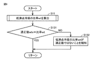
- FIG. 9 is a flowchart for explaining processing performed by the control device 12 of FIG. 1 to notify the user that the ratio of the low boiling point refrigerant is different from the appropriate value.
- the processing shown in FIG. 9 is performed periodically or when a predetermined event occurs by a main routine (not shown) performed by the control device 12 for controlling the air conditioner 1.
- the control device 12 calculates the ratio wt of the low boiling point refrigerant in S11, and advances the process to S131.
- the control device 12 determines whether or not the low-boiling-point refrigerant ratio wt is equal to the appropriate value wtv.
- the absolute value of the difference between the low-boiling-point refrigerant ratio wt and the appropriate value wtv is smaller than the threshold value, it may be determined that both are equal.
- the control device 12 When the low boiling point refrigerant ratio wt is not equal to the appropriate value wtv (NO in S131), the control device 12 notifies the notification unit 13 to notify that the low boiling point refrigerant ratio wt is not the appropriate value wtv in S132. Control and return processing to the main routine. Examples of the notification method include voice, lighting of a lamp, and transmission of a message. When the ratio wt of the low boiling point refrigerant is equal to the appropriate value wtv (YES in S131), the control device 12 returns the process to the main routine.
- the user can know that the ratio of the low-boiling-point refrigerant has changed during the operation of the air conditioner 1.
- the user can quickly respond to an abnormality related to the refrigerant, such as leakage of a low-boiling-point refrigerant or incorrect charging of the refrigerant.
- the ratio of the low boiling point refrigerant in the non-azeotropic refrigerant mixture circulating in the air conditioner 1 is changed, there may be no abnormality.
- the user intentionally changes the refrigerant of the air conditioner 1 to a refrigerant having a lower GWP. Therefore, it is desirable that the appropriate value wtv can be reset by the user to, for example, the value input by the user or the ratio wt of the low-boiling-point refrigerant at the time of notification in S113.
- FIG. 10 also shows a decrease in the ratio of the low-boiling refrigerant with time (a), a decrease in the amount of the non-azeotropic refrigerant mixture (b), and a decrease in the coefficient of performance (COP) (c).
- COP is an index that serves as a measure of the energy consumption efficiency of the air conditioner 1, and means that the larger the value, the better the energy consumption efficiency of the air conditioner 1.
- the ratio of the low boiling point refrigerant decreases with time as shown in FIG.
- the ratio of the low boiling point refrigerant decreases, as shown in FIG. 10B, the total amount of the non-azeotropic refrigerant mixture also decreases.
- the COP of the air conditioner 1 also decreases as shown in FIG. A decrease in COP means a decrease in air conditioning capability of the air conditioner 1. If the COP is too low, air conditioning operation is often difficult. Therefore, when the COP falls below the lower limit value cps, the air conditioning operation is usually forcibly stopped.
- an index value relating to a decreasing tendency of the non-azeotropic refrigerant mixture (dotted line portion in FIG. 10A) is calculated from the calculation history of the ratio of the low boiling refrigerant continuously calculated, Using the index value, the ratio of the low boiling point refrigerant after a predetermined time has elapsed is predicted. If air-conditioning operation at the predicted low boiling point refrigerant ratio becomes difficult, the user is prompted to perform maintenance including, for example, filling and replacing of non-azeotropic refrigerant mixture or maintenance of piping.
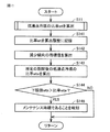
- FIG. 11 is a flowchart for explaining a maintenance time determination process performed in the control device 12 of FIG.
- the processing shown in FIG. 11 is performed periodically or when a predetermined event occurs by a main routine (not shown) performed by the control device 12 for controlling the air conditioner 1.
- the storage unit 122 stores a calculation history of the low boiling point refrigerant ratio wt.
- the control device 12 calculates the ratio wt of the low-boiling refrigerant in S11, and advances the process to S141.
- the control device 12 records the ratio wt in the calculation history, and advances the process to S142.
- the control device 12 uses the calculation history in S142 to calculate, for example, a rate of decrease in the ratio of the low boiling point refrigerant per day as an index value relating to the decreasing tendency of the ratio of the low boiling point refrigerant, and advances the process to S143.
- the controller 12 calculates the low-boiling-point refrigerant ratio wete after one month, for example, in S143, and advances the process to S144.
- the control device 12 determines whether or not the ratio weight predicted in S144 is smaller than the lower limit value wts. It is desirable that the lower limit value wts be a ratio of the low boiling point refrigerant corresponding to the COP at a level where the air conditioning operation becomes difficult.
- the lower limit value wts can be appropriately determined by actual machine experiments or simulations.
- the control device 12 controls the notification unit 13 to notify the user that it is a maintenance time in S145, and returns the process to the main routine.
- Examples of the notification method include voice, lighting of a lamp, and transmission of a message.
- the control device 12 returns the process to the main routine.
- the pipe through which the liquid refrigerant from the first heat exchanger 120 and the pipe through which the wet steam from the capillary 141 flow are the first heat.
- the flow of the liquid refrigerant from the exchanger 120 and the flow of the wet steam from the capillary 141 are arranged so as to face each other.
- a temperature gradient occurs in wet steam under a constant pressure, and the temperature rises with an increase in enthalpy.
- the wet steam from the capillary 141 proceeds through the piping inside the second heat exchanger 130 while receiving heat from the liquid refrigerant from the first heat exchanger 120. Therefore, the temperature of the wet steam from the capillary 141 rises as it travels through the piping of the second heat exchanger 130.
- the liquid refrigerant from the first heat exchanger 120 advances through the piping inside the second heat exchanger 130 while applying heat to the liquid refrigerant from the capillary 141. Therefore, the temperature of the liquid refrigerant from the first heat exchanger 120 decreases as it proceeds through the piping of the second heat exchanger 130. Since the flow of the liquid refrigerant from the first heat exchanger 120 and the flow of the wet steam from the capillary 141 are in opposite directions, the temperature difference between the liquid refrigerant from the first heat exchanger 120 and the wet steam from the capillary 141. Can be kept substantially constant from one end of the second heat exchanger 130 to the other end.
- the non-azeotropic refrigerant mixture can continue heat exchange stably while passing through the second heat exchanger 130.
- the efficiency of heat exchange can be improved as compared with the case where the flow of the wet steam from the liquid refrigerant from the first heat exchanger 120 and the wet steam from the capillary 141 are in the same direction.
- the size of the second heat exchanger 130 is larger than when the flow of the liquid refrigerant from the first heat exchanger 120 and the flow of the wet steam from the capillary 141 are in the same direction. Can be reduced.
- the air conditioning capability of the air conditioner 1 can be improved.
- the temperature sensor 131 has been described for measuring the temperature T1 of the refrigerant flowing between the connection point JB and the second heat exchanger 130.
- the refrigerant whose temperature is measured by the temperature sensor 131 may be any refrigerant that flows between the first heat exchanger 120 and the second heat exchanger 130.
- the temperature sensor 131 may measure the temperature of the refrigerant flowing between the first heat exchanger 120 and the connection point JB.
- the temperature sensor 132 demonstrated the case where the temperature T2 of the refrigerant
- the refrigerant whose temperature is measured by the temperature sensor 132 may be any refrigerant that flows between the second heat exchanger 130 and the expansion valve 140.
- the temperature sensor 132 may measure the temperature of the refrigerant flowing between the connection point JA and the expansion valve 140.
- the ratio of the low boiling point refrigerant in the non-azeotropic refrigerant mixture circulating in the air conditioner 1 can be calculated without using a pressure sensor. As a result, it is possible to detect a change in the composition ratio of the non-azeotropic refrigerant mixture while suppressing the manufacturing cost of the air conditioner 1.
- FIG. 12 is a functional block diagram showing a configuration of an air-conditioning apparatus 1A according to a modification of the first embodiment.
- the difference between the air conditioners 1 and 1A is that the capillaries 141 and the capillaries 142 in the air conditioner 1 are replaced with expansion valves 141A and 142A in the air conditioner 1A, and the openings of the expansion valves 141A and 142A. Is controlled by the control device 12A. Since the configuration other than these is the same as that of the air conditioner 1, description thereof will not be repeated.
- the non-azeotropic refrigerant mixture is bypassed to the compressor 110 in such a case, the amount of the non-azeotropic refrigerant mixture passing through the third heat exchanger 150 becomes too small, and the air conditioning capability of the air conditioner 1A Can be significantly reduced.
- the first bypass flow path and the second bypass flow are closed by closing the expansion valves 141A and 142A.
- a non-azeotropic refrigerant mixture is not bypassed to the compressor 110 using the flow path.
- the reference frequency fs2 can be calculated by an actual machine experiment or simulation.
- the reference frequency fs2 is preferably calculated as a drive frequency corresponding to the capacity of the compressor 110 such that the pressure loss in the third heat exchanger 150 hardly affects the air conditioning capability of the air conditioner 1. .
- FIG. 13 is a flowchart for explaining processing for controlling the expansion valves 141A and 142A performed by the control device 12A of FIG.
- it is necessary to calculate the ratio of the low boiling point refrigerant by a main routine (not shown) performed by the control device 12A for controlling the air conditioner 1A or a subroutine (not shown) called from the main routine. Done in some cases.
- control device 12A determines whether or not the drive frequency f of the compressor 110 is greater than the reference frequency fs2 in S151.
- drive frequency f is greater than reference frequency fs2 (YES in S151)
- control device 12A adjusts the opening degree of expansion valves 141A and 142A in S152, respectively, and decompression of the non-azeotropic refrigerant mixture by expansion valves 141A and 142A is performed. If so, the process proceeds to S11.
- the control device 12A calculates the ratio wt of the low boiling point refrigerant in S11, and returns the process to the main routine or subroutine.
- drive frequency f is equal to or lower than reference frequency fs2 (NO in S151)
- control device 12A sets the opening of each of expansion valves 141A and 142A to 0 in S153, and returns the process to the main routine or subroutine.
- the ratio of the low boiling point refrigerant in the non-azeotropic refrigerant mixture circulating in the air conditioner 1A can be calculated without using a pressure sensor. As a result, it is possible to detect a change in the composition ratio of the non-azeotropic refrigerant mixture while suppressing the manufacturing cost of the air conditioner 1.
- Embodiment 1A the air conditioning of the air conditioner 1A when the capacity of the compressor 110 is reduced to such an extent that the pressure loss in the third heat exchanger 150 hardly affects the air conditioning capacity of the air conditioner 1A. A decrease in ability can be suppressed.
- Embodiment 2 In Embodiment 1, the case where the cooling operation is performed by circulating the refrigerant in the order of the compressor 110, the first heat exchanger 120, the expansion valve 140, and the third heat exchanger 150 has been described. In the second embodiment, a case where the cooling operation and the heating operation can be switched will be described.
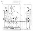
- FIG. 14 is a functional block diagram showing the configuration of the air-conditioning apparatus 2 according to Embodiment 2 during the cooling operation.
- FIG. 15 is a functional block diagram illustrating a configuration of the air-conditioning apparatus 2 according to Embodiment 2 during a heating operation.
- the air conditioner 2 further includes an expansion valve 240 and a four-way valve 170 that switches the refrigerant flow path in addition to the configuration of the air conditioner 1.
- Control device 22 further receives signals from temperature sensors 251 and 252.
- the control device 22 adjusts the opening degree of the expansion valves 140 and 240.
- the temperature sensor 251 measures the temperature T7 of the refrigerant flowing between the expansion valve 240 and the first heat exchanger 120.
- the temperature sensor 252 measures the temperature T8 of the refrigerant flowing between the first heat exchanger 120 and the compressor 110. Since other configurations are the same as those in the first embodiment, description thereof will not be repeated.
- the four-way valve 170 is controlled by the control device 22 to form a flow path so that the non-azeotropic refrigerant mixture from the third heat exchanger 150 flows to the compressor 110.
- the non-azeotropic refrigerant mixture from the compressor 110 is formed to flow to the first heat exchanger 120.
- the control device 22 controls the expansion valve 240 during the cooling operation so that the opening degree of the expansion valve 240 is larger than the reference opening degree so that the decompression by the expansion valve 240 is hardly performed.
- the non-azeotropic refrigerant mixture circulates in the order of the compressor 110, the first heat exchanger 120, the second heat exchanger 130, the expansion valve 140, and the third heat exchanger 150.
- the first heat exchanger 120 functions as a condenser
- the third heat exchanger 150 functions as an evaporator.
- the Ph diagram during the cooling operation is the same as the Ph diagram (see FIG. 5) in the first embodiment.
- the control device 22 performs the superheat degree control process shown in FIG. 6 during the cooling operation as in the first embodiment.
- the four-way valve 170 is controlled by the control device 22 to form a flow path so that the non-azeotropic refrigerant mixture from the first heat exchanger 120 flows to the compressor 110.
- a flow path is formed so that the refrigerant from the compressor 110 flows to the third heat exchanger 150.
- the control device 22 controls the expansion valve 140 during the heating operation so that the opening degree of the expansion valve 140 is larger than the reference opening degree so that the decompression by the expansion valve 140 is hardly performed.
- the non-azeotropic refrigerant mixture circulates in the order of the compressor 110, the third heat exchanger 150, the second heat exchanger 130, the expansion valve 240, and the first heat exchanger 120.
- the first heat exchanger 120 functions as an evaporator
- the third heat exchanger 150 functions as a condenser.
- FIG. 16 is a Ph diagram showing the relationship between the pressure of the non-azeotropic refrigerant mixture and enthalpy in the air conditioner 2 of FIG.
- the circulation of the non-azeotropic refrigerant mixture in the air conditioner 2 is represented as a cycle C2 that returns from the point R21 to the point R21 via the point R22, the point R23, the point R24, and the point R25.
- the state change from the point R21 to the point R22 represents a process of compression of the non-azeotropic refrigerant mixture by the compressor 110.
- the state change from the point R22 to the point R23 represents the process of condensing the non-azeotropic refrigerant mixture by the third heat exchanger 150.
- the state change from the point R23 to the point R24 represents the process of cooling the non-azeotropic refrigerant mixture by the second heat exchanger 130.
- the state change from the point R24 to the point R25 represents a process of adiabatic expansion of the non-azeotropic refrigerant mixture by the expansion valve 240.
- the state change from the point R25 to the point R21 represents the process of evaporation of the non-azeotropic refrigerant mixture by the first heat exchanger 120.
- the non-azeotropic refrigerant mixture flowing between the expansion valve 240 and the first heat exchanger 120 is in a state of a point R25 that is the starting point of the evaporation process by the first heat exchanger 120.
- the non-azeotropic refrigerant mixture flowing between the compressor 110 and the third heat exchanger 150 is in a state of a point R21 that is the end point of the evaporation process by the first heat exchanger 120.
- the non-azeotropic refrigerant mixture flowing between the second heat exchanger 130 and the connection point JB is after being cooled by the second heat exchanger 130, and thus is in a state of point R24.
- the non-azeotropic refrigerant mixture flowing between the capillary 142 and the connection point JC is a non-azeotropic refrigerant mixture in the state of the point R24 decompressed in an adiabatic state by the expansion valve 141A.
- the enthalpy is equal to the enthalpy at point R24.
- the expansion valve 141 ⁇ / b> A is connected to a flow path between the first heat exchanger 120 and the compressor 110 via the second bypass flow path 162 and the first bypass flow path 161.
- the pressure of the non-azeotropic refrigerant mixture whose temperature T4 is measured by the temperature sensor 134 is approximately equal to the pressure at the point R21 corresponding to the refrigerant state between the first heat exchanger 120 and the compressor 110.
- Point R ⁇ b> 21 is an end point of the evaporation process by the first heat exchanger 120.
- the pressure of the evaporation process by the first heat exchanger 120 is substantially constant.
- the pressure at point R21 is substantially equal to the pressure at point R25, which is the starting point of the evaporation process.
- the enthalpy of point R25 is equal to the enthalpy of point R24.
- the non-azeotropic refrigerant mixture flowing between the capillary 142 and the connection point JC is in a state of point R25.
- the non-azeotropic refrigerant mixture flowing between the connection point JA and the second heat exchanger 130 is before cooling by the second heat exchanger 130, it is in a state of point R23.
- the non-azeotropic refrigerant mixture flowing between the capillary 141 and the connection point JC is the one after the non-azeotropic refrigerant mixture in the state of the point R23 has been decompressed in the adiabatic state by the capillary 142.
- the enthalpy is approximately equal to the enthalpy at point R23.
- the expansion valve 142 ⁇ / b> A is connected to the flow path between the first heat exchanger 120 and the compressor 110 via the first bypass flow path 161.
- the pressure of the non-azeotropic refrigerant mixture flowing between the capillary 141 and the connection point JC is the pressure of the point R21 corresponding to the state of the non-azeotropic refrigerant mixture between the first heat exchanger 120 and the compressor 110. Almost equal.
- Point R21 is the end point of the evaporation process. The pressure of the evaporation process is almost constant.
- the non-azeotropic refrigerant mixture flowing between the capillary 141 and the connection point JC is in a state of a point R26 where the enthalpy is substantially equal to the point R23 in the evaporation process.
- a temperature gradient has occurred.
- the absolute value ⁇ T12 of the difference between the temperatures T1 and T2, the absolute value ⁇ T34 of the difference between the temperatures T3 and T4, and the ratio of the low-boiling refrigerant have a predetermined correspondence relationship ( The ratio of the low-boiling-point refrigerant is calculated by utilizing the fact that it exists in FIG.
- the correspondence used for calculating the ratio of the low boiling point refrigerant in the cooling operation can be used as it is in the heating operation. .
- FIG. 17 is a flowchart for explaining the superheat degree control performed in the control device 22 according to the second embodiment.
- the processing shown in FIG. 17 is performed periodically or when a predetermined event occurs by a main routine (not shown) performed by the control device 22 for controlling the air conditioner 2.
- the control device 22 calculates the ratio wt of the low boiling point refrigerant in S11, and advances the process to S12.
- the controller 22 calculates the temperature gradient ⁇ TG in S12, and advances the process to S13.
- the temperature gradient ⁇ TG is the difference between the temperature at the point SG2 and the temperature at the point SL2 in FIG.
- control device 22 sets target superheat degree SH in S13, and advances the process to S14.
- control device 22 determines whether or not temperature difference ⁇ T87 is equal to the sum of temperature gradient ⁇ TG and target superheat degree SH.
- the temperature difference ⁇ T87, the temperature gradient ⁇ T, and the sum of the target superheat degree SH are It may be determined that they are equal.
- control device 22 advances the process to S22A.
- the control device 22 controls the opening degree of the expansion valve 240 so that the temperature difference ⁇ T87 becomes equal to the sum of the temperature gradient ⁇ TG and the target superheat degree SH, and then returns the process to the main routine.
- control device 22 returns the process to the main routine.
- the ratio of the low boiling point refrigerant in the non-azeotropic refrigerant mixture circulating in the air conditioner 2 can be calculated without using a pressure sensor. As a result, it is possible to detect a change in the composition ratio of the non-azeotropic refrigerant mixture while suppressing the manufacturing cost of the air conditioner 1.
- the ratio of the low boiling point refrigerant can be calculated.
- Embodiments 1 and 2 have described the case where the non-azeotropic refrigerant mixture circulates in the air conditioner.
- the refrigerant circulating through the air conditioner may be a single refrigerant. Even when the refrigerant circulating through the air conditioner is a single refrigerant, air conditioning by the air conditioners 1 and 2 is possible.
Landscapes
- Engineering & Computer Science (AREA)
- Chemical & Material Sciences (AREA)
- Physics & Mathematics (AREA)
- Thermal Sciences (AREA)
- Mechanical Engineering (AREA)
- General Engineering & Computer Science (AREA)
- Combustion & Propulsion (AREA)
- Chemical Kinetics & Catalysis (AREA)
- Materials Engineering (AREA)
- Organic Chemistry (AREA)
- Air Conditioning Control Device (AREA)
Abstract
Priority Applications (4)
| Application Number | Priority Date | Filing Date | Title |
|---|---|---|---|
| US16/078,822 US11175072B2 (en) | 2016-03-23 | 2016-03-23 | Air conditioner |
| GB1813532.7A GB2563162B (en) | 2016-03-23 | 2016-03-23 | Air conditioner |
| PCT/JP2016/059205 WO2017163339A1 (fr) | 2016-03-23 | 2016-03-23 | Dispositif de climatisation |
| JP2018506679A JP6567167B2 (ja) | 2016-03-23 | 2016-03-23 | 空気調和装置 |
Applications Claiming Priority (1)
| Application Number | Priority Date | Filing Date | Title |
|---|---|---|---|
| PCT/JP2016/059205 WO2017163339A1 (fr) | 2016-03-23 | 2016-03-23 | Dispositif de climatisation |
Publications (1)
| Publication Number | Publication Date |
|---|---|
| WO2017163339A1 true WO2017163339A1 (fr) | 2017-09-28 |
Family
ID=59901289
Family Applications (1)
| Application Number | Title | Priority Date | Filing Date |
|---|---|---|---|
| PCT/JP2016/059205 Ceased WO2017163339A1 (fr) | 2016-03-23 | 2016-03-23 | Dispositif de climatisation |
Country Status (4)
| Country | Link |
|---|---|
| US (1) | US11175072B2 (fr) |
| JP (1) | JP6567167B2 (fr) |
| GB (1) | GB2563162B (fr) |
| WO (1) | WO2017163339A1 (fr) |
Families Citing this family (5)
| Publication number | Priority date | Publication date | Assignee | Title |
|---|---|---|---|---|
| WO2019049255A1 (fr) * | 2017-09-07 | 2019-03-14 | 三菱電機株式会社 | Dispositif de climatisation |
| CN109386985B (zh) * | 2018-10-22 | 2020-07-28 | 广东美的暖通设备有限公司 | 两管制喷气增焓室外机及多联机系统 |
| JP7012208B2 (ja) * | 2019-01-18 | 2022-01-28 | パナソニックIpマネジメント株式会社 | 冷凍サイクル装置及びそれを備えた液体加熱装置 |
| WO2020174619A1 (fr) * | 2019-02-27 | 2020-09-03 | 三菱電機株式会社 | Dispositif de climatisation |
| JP7216308B2 (ja) * | 2021-03-31 | 2023-02-01 | ダイキン工業株式会社 | 冷凍サイクル装置 |
Citations (3)
| Publication number | Priority date | Publication date | Assignee | Title |
|---|---|---|---|---|
| JP2005114184A (ja) * | 2003-10-03 | 2005-04-28 | Hitachi Ltd | 冷媒充填装置及び冷媒充填方法 |
| JP2011179697A (ja) * | 2010-02-26 | 2011-09-15 | Panasonic Corp | 冷凍サイクル装置および冷温水装置 |
| WO2013111177A1 (fr) * | 2012-01-24 | 2013-08-01 | 三菱電機株式会社 | Unité de climatisation |
Family Cites Families (20)
| Publication number | Priority date | Publication date | Assignee | Title |
|---|---|---|---|---|
| US933682A (en) * | 1908-07-03 | 1909-09-07 | Gardner Tufts Voorhees | Multiple-effect receiver. |
| US4947655A (en) * | 1984-01-11 | 1990-08-14 | Copeland Corporation | Refrigeration system |
| US4643002A (en) * | 1985-09-26 | 1987-02-17 | Carrier Corporation | Continuous metered flow multizone air conditioning system |
| US5095712A (en) * | 1991-05-03 | 1992-03-17 | Carrier Corporation | Economizer control with variable capacity |
| US5228301A (en) * | 1992-07-27 | 1993-07-20 | Thermo King Corporation | Methods and apparatus for operating a refrigeration system |
| JP3140923B2 (ja) * | 1994-11-25 | 2001-03-05 | 三菱電機株式会社 | 冷媒循環システムおよび冷凍・空調装置 |
| JPH0854161A (ja) | 1994-08-11 | 1996-02-27 | Sanyo Electric Co Ltd | 冷凍装置の冷媒漏洩検出方法 |
| JPH08254363A (ja) | 1995-03-15 | 1996-10-01 | Toshiba Corp | 空調制御装置 |
| JP3140333B2 (ja) * | 1995-07-14 | 2001-03-05 | 株式会社クボタ | ヒートポンプ装置 |
| JPH11159895A (ja) | 1997-11-28 | 1999-06-15 | Hitachi Ltd | 空気調和装置 |
| DE60037445T2 (de) * | 1999-10-18 | 2008-12-04 | Daikin Industries, Ltd. | Kältevorrichtung |
| JP3749092B2 (ja) * | 2000-07-25 | 2006-02-22 | 三菱電機株式会社 | 冷媒封入方法および空気調和機 |
| AU2003213443B2 (en) * | 2002-03-18 | 2005-05-05 | Daikin Industries, Ltd. | Pressure control device of air conditioner and air conditioner having the device |
| KR100569547B1 (ko) * | 2002-08-02 | 2006-04-10 | 다이킨 고교 가부시키가이샤 | 냉동 장치 |
| US6758054B2 (en) * | 2002-11-19 | 2004-07-06 | Delphi Technologies, Inc. | Dual evaporator air conditioning system and method of use |
| JP2004218964A (ja) * | 2003-01-16 | 2004-08-05 | Matsushita Electric Ind Co Ltd | 冷凍装置 |
| US6817205B1 (en) * | 2003-10-24 | 2004-11-16 | Carrier Corporation | Dual reversing valves for economized heat pump |
| US7000423B2 (en) * | 2003-10-24 | 2006-02-21 | Carrier Corporation | Dual economizer heat exchangers for heat pump |
| US6892553B1 (en) * | 2003-10-24 | 2005-05-17 | Carrier Corporation | Combined expansion device and four-way reversing valve in economized heat pumps |
| JP6790966B2 (ja) * | 2017-03-31 | 2020-11-25 | ダイキン工業株式会社 | 空気調和装置 |
-
2016
- 2016-03-23 WO PCT/JP2016/059205 patent/WO2017163339A1/fr not_active Ceased
- 2016-03-23 US US16/078,822 patent/US11175072B2/en active Active
- 2016-03-23 JP JP2018506679A patent/JP6567167B2/ja active Active
- 2016-03-23 GB GB1813532.7A patent/GB2563162B/en not_active Expired - Fee Related
Patent Citations (3)
| Publication number | Priority date | Publication date | Assignee | Title |
|---|---|---|---|---|
| JP2005114184A (ja) * | 2003-10-03 | 2005-04-28 | Hitachi Ltd | 冷媒充填装置及び冷媒充填方法 |
| JP2011179697A (ja) * | 2010-02-26 | 2011-09-15 | Panasonic Corp | 冷凍サイクル装置および冷温水装置 |
| WO2013111177A1 (fr) * | 2012-01-24 | 2013-08-01 | 三菱電機株式会社 | Unité de climatisation |
Also Published As
| Publication number | Publication date |
|---|---|
| GB2563162A (en) | 2018-12-05 |
| JP6567167B2 (ja) | 2019-08-28 |
| GB2563162B (en) | 2020-10-21 |
| JPWO2017163339A1 (ja) | 2018-12-13 |
| US11175072B2 (en) | 2021-11-16 |
| US20190049155A1 (en) | 2019-02-14 |
| GB201813532D0 (en) | 2018-10-03 |
Similar Documents
| Publication | Publication Date | Title |
|---|---|---|
| US10018388B2 (en) | Heat source side unit and refrigeration cycle apparatus | |
| US20230134047A1 (en) | Refrigeration cycle apparatus and refrigeration apparatus | |
| JP6567167B2 (ja) | 空気調和装置 | |
| CN105627649B (zh) | 冷冻循环装置 | |
| US10082324B2 (en) | Refrigeration apparatus having leakage or charge deficiency determining feature | |
| JP6656402B2 (ja) | 冷凍サイクル装置 | |
| JP6594599B1 (ja) | 空気調和装置 | |
| JP2017053566A (ja) | 冷凍サイクル装置 | |
| JP5893151B2 (ja) | 空調給湯複合システム | |
| JP5908183B1 (ja) | 空気調和装置 | |
| JPWO2020208714A1 (ja) | 冷凍装置 | |
| JP3463710B2 (ja) | 非共沸混合冷媒搭載の冷凍装置 | |
| WO2013168199A1 (fr) | Climatiseur | |
| JP2943613B2 (ja) | 非共沸混合冷媒を用いた冷凍空調装置 | |
| JP2948105B2 (ja) | 非共沸混合冷媒を用いた冷凍空調装置 | |
| JP6739664B2 (ja) | 冷凍空調装置及び制御装置 | |
| JP6896076B2 (ja) | 冷凍サイクル装置 | |
| JP5672290B2 (ja) | 空気調和機 | |
| WO2017179210A1 (fr) | Dispositif de réfrigération | |
| JP2007139244A (ja) | 冷凍装置 | |
| JP6762422B2 (ja) | 冷凍サイクル装置 | |
| WO2023002520A1 (fr) | Dispositif à cycle frigorifique et dispositif de climatisation | |
| JP6758075B2 (ja) | 空気調和機及び冷媒量判定方法 | |
| JP7341337B2 (ja) | 冷熱源ユニット、冷凍サイクル装置および冷凍機 | |
| JP7630648B2 (ja) | 冷凍サイクル装置 |
Legal Events
| Date | Code | Title | Description |
|---|---|---|---|
| ENP | Entry into the national phase |
Ref document number: 201813532 Country of ref document: GB Kind code of ref document: A Free format text: PCT FILING DATE = 20160323 |
|
| WWE | Wipo information: entry into national phase |
Ref document number: 1813532.7 Country of ref document: GB |
|
| WWE | Wipo information: entry into national phase |
Ref document number: 2018506679 Country of ref document: JP |
|
| NENP | Non-entry into the national phase |
Ref country code: DE |
|
| 121 | Ep: the epo has been informed by wipo that ep was designated in this application |
Ref document number: 16895375 Country of ref document: EP Kind code of ref document: A1 |
|
| 122 | Ep: pct application non-entry in european phase |
Ref document number: 16895375 Country of ref document: EP Kind code of ref document: A1 |