WO2017163479A1 - Dispositif de détection de charge - Google Patents
Dispositif de détection de charge Download PDFInfo
- Publication number
- WO2017163479A1 WO2017163479A1 PCT/JP2016/082850 JP2016082850W WO2017163479A1 WO 2017163479 A1 WO2017163479 A1 WO 2017163479A1 JP 2016082850 W JP2016082850 W JP 2016082850W WO 2017163479 A1 WO2017163479 A1 WO 2017163479A1
- Authority
- WO
- WIPO (PCT)
- Prior art keywords
- load detection
- electrode
- detection sensor
- elastic support
- sheet
- Prior art date
- Legal status (The legal status is an assumption and is not a legal conclusion. Google has not performed a legal analysis and makes no representation as to the accuracy of the status listed.)
- Ceased
Links
Images






Classifications
-
- G—PHYSICS
- G05—CONTROLLING; REGULATING
- G05B—CONTROL OR REGULATING SYSTEMS IN GENERAL; FUNCTIONAL ELEMENTS OF SUCH SYSTEMS; MONITORING OR TESTING ARRANGEMENTS FOR SUCH SYSTEMS OR ELEMENTS
- G05B19/00—Program-control systems
- G05B19/02—Program-control systems electric
- G05B19/18—Numerical control [NC], i.e. automatically operating machines, in particular machine tools, e.g. in a manufacturing environment, so as to execute positioning, movement or co-ordinated operations by means of program data in numerical form
- G05B19/406—Numerical control [NC], i.e. automatically operating machines, in particular machine tools, e.g. in a manufacturing environment, so as to execute positioning, movement or co-ordinated operations by means of program data in numerical form characterised by monitoring or safety
-
- B—PERFORMING OPERATIONS; TRANSPORTING
- B60—VEHICLES IN GENERAL
- B60N—SEATS SPECIALLY ADAPTED FOR VEHICLES; VEHICLE PASSENGER ACCOMMODATION NOT OTHERWISE PROVIDED FOR
- B60N2/00—Seats specially adapted for vehicles; Arrangement or mounting of seats in vehicles
- B60N2/70—Upholstery springs ; Upholstery
- B60N2/7094—Upholstery springs
-
- B—PERFORMING OPERATIONS; TRANSPORTING
- B60—VEHICLES IN GENERAL
- B60N—SEATS SPECIALLY ADAPTED FOR VEHICLES; VEHICLE PASSENGER ACCOMMODATION NOT OTHERWISE PROVIDED FOR
- B60N2/00—Seats specially adapted for vehicles; Arrangement or mounting of seats in vehicles
- B60N2/90—Details or parts not otherwise provided for
-
- B—PERFORMING OPERATIONS; TRANSPORTING
- B60—VEHICLES IN GENERAL
- B60N—SEATS SPECIALLY ADAPTED FOR VEHICLES; VEHICLE PASSENGER ACCOMMODATION NOT OTHERWISE PROVIDED FOR
- B60N2/00—Seats specially adapted for vehicles; Arrangement or mounting of seats in vehicles
- B60N2/002—Seats provided with an occupancy detection means mounted therein or thereon
- B60N2/0021—Seats provided with an occupancy detection means mounted therein or thereon characterised by the type of sensor or measurement
-
- H—ELECTRICITY
- H01—ELECTRIC ELEMENTS
- H01H—ELECTRIC SWITCHES; RELAYS; SELECTORS; EMERGENCY PROTECTIVE DEVICES
- H01H13/00—Switches having rectilinearly-movable operating part or parts adapted for pushing or pulling in one direction only, e.g. push-button switch
- H01H13/02—Details
- H01H13/12—Movable parts; Contacts mounted thereon
- H01H13/14—Operating parts, e.g. push-button
- H01H13/16—Operating parts, e.g. push-button adapted for operation by a part of the human body other than the hand, e.g. by foot
-
- B—PERFORMING OPERATIONS; TRANSPORTING
- B60—VEHICLES IN GENERAL
- B60N—SEATS SPECIALLY ADAPTED FOR VEHICLES; VEHICLE PASSENGER ACCOMMODATION NOT OTHERWISE PROVIDED FOR
- B60N2/00—Seats specially adapted for vehicles; Arrangement or mounting of seats in vehicles
- B60N2/002—Seats provided with an occupancy detection means mounted therein or thereon
- B60N2/0021—Seats provided with an occupancy detection means mounted therein or thereon characterised by the type of sensor or measurement
- B60N2/003—Seats provided with an occupancy detection means mounted therein or thereon characterised by the type of sensor or measurement characterised by the sensor mounting location in or on the seat
- B60N2/0032—Seats provided with an occupancy detection means mounted therein or thereon characterised by the type of sensor or measurement characterised by the sensor mounting location in or on the seat mounted on springs
-
- B—PERFORMING OPERATIONS; TRANSPORTING
- B60—VEHICLES IN GENERAL
- B60N—SEATS SPECIALLY ADAPTED FOR VEHICLES; VEHICLE PASSENGER ACCOMMODATION NOT OTHERWISE PROVIDED FOR
- B60N2210/00—Sensor types, e.g. for passenger detection systems or for controlling seats
- B60N2210/40—Force or pressure sensors
- B60N2210/46—Electric switches
Definitions
- the present invention relates to a load detection device and is suitable for detecting a load applied according to seating or the like.
- an alarm system that warns that a seat belt is not worn when riding is put into practical use.
- a warning is issued when the seat belt is not detected while a person is seated.
- a load detection device that detects a load applied in accordance with the seating may be used.
- Some of such load detection devices are arranged under the seat cushion of the seat.
- the seat cushion In the seat, there are a case where the seat cushion is arranged on the seat pan and a case where the seat cushion is arranged on a plurality of S springs fixed to the frame.
- the load detection device In a seat in which a seat cushion is disposed on a plurality of S springs, the load detection device may be used while being locked to the S springs.
- Patent Document 1 listed below describes such a load detection device.
- the load detection device described in Patent Literature 1 includes a pedestal that is locked to an S spring, and a membrane switch that is disposed on the pedestal via a spacer.
- the following configuration can be considered. That is, it is conceivable to provide the switch with a pressing member that turns on the load detection sensor when the pressure receiving surface that receives the pressure from the seat cushion of the seat is pressed.
- the pressure member becomes unstable due to the movement of the pressing member, and there is a concern that abnormal noise may occur due to contact with other members according to the movement of the pressing member.
- an object of the present invention is to provide a load detection device that can appropriately detect a load while suppressing the occurrence of abnormal noise.
- a load detection device has a load detection sensor and a pressure receiving surface that receives pressure from a seat cushion, and the load detection sensor is configured by pressing the pressure receiving surface against the seat cushion.
- a pressing member for pressing and an elastic support portion for supporting the pressing member from the load detection sensor side are provided.
- a pressure detection surface of the pressing member is opposed to the lower surface of a seat cushion such as a seat or a bed, and the pressure detection member is pressed from the pressing member.
- an elastic support part to support. Since the pressing member is supported from the load detection sensor side by the elastic support portion, when the load is not applied to the load detection sensor, the pressing member moves and contacts other members, and abnormal noise caused by the contact is generated. Occurrence can be prevented. Further, the movement when the pressing member presses the load detection sensor in response to the pressing from the seat cushion is also alleviated.
- the load detection device can appropriately detect the load while suppressing the occurrence of abnormal noise.
- the said pressure receiving surface moves with respect to the said mounting surface so that the angle with respect to the mounting surface in which the said load detection sensor is mounted changes.
- the pressure receiving surface can follow the inclination. Therefore, the pressure receiving surface is appropriately pressed against the lower surface of the seat cushion, and the load can be detected appropriately.
- the load detection sensor includes: a first electrode sheet including at least one first electrode; and a second electrode that is disposed closer to the pressing member than the first electrode sheet and faces the first electrode.
- the second electrode sheet includes a metal plate on the pressing member side, and a part of the metal plate is used as the elastic support portion.
- the second electrode sheet since the second electrode sheet includes a metal plate on the pressing member side, the flexibility does not easily change even when the temperature changes. Therefore, even when the environmental temperature around the load detection device changes, the bending method of the metal plate pressed by the pressing member is hardly changed. Moreover, since a part of metal plate is an elastic support part, even when the environmental temperature around a load detection apparatus changes, the elastic force of an elastic support part does not change easily. Therefore, according to the load detection device, erroneous detection such as seating can be suppressed even when the environmental temperature changes.
- the second electrode sheet is made of a metal plate, and a portion of the metal plate that faces the first electrode through the opening is the second electrode, and the other portion of the metal plate is the elastic support. It is preferable to be a part.
- the metal plate plays a role as an electrode constituting one of the switches and a role as a support portion for supporting the pressing member. For this reason, it is possible to appropriately detect the load while suppressing the generation of abnormal noise while suppressing the number of parts of the load detection sensor.
- the second electrode sheet includes an insulating sheet on which the second electrode is provided and the metal plate disposed on a surface of the insulating sheet on the pressing member side.
- the load detection device can be reduced in size and space.
- connection maintaining unit that maintains electrical connection even when an external pressure is not applied between a part of the first electrode sheet and a part of the second electrode sheet is configured, and the first component that configures the connection maintaining unit It is preferable that a part of the two-electrode sheet also serves as the elastic support portion.
- the circuit formed on the first electrode sheet and the circuit formed on the second electrode sheet are always in a conductive state via the connection maintaining unit. For this reason, even when the number of switches connected in series in the circuit in the load detection sensor is an odd number, in the load detection sensor, only one of the first electrode sheet and the second electrode sheet is used as the pair of terminals of the circuit. Can be arranged.
- a part of the second electrode sheet constituting the connection maintaining portion also serves as an elastic support portion, a force acts on the elastic support portion on the first electrode sheet side as a repulsive force, and the connection maintaining portion is configured. A force acts on the first electrode sheet side also in a part of the two-electrode sheet.
- connection state of a connection maintenance part can be made stronger.
- the metal plate plays a role of arranging the pair of terminals on one electrode sheet and a role as a support portion for supporting the pressing member. For this reason, it is possible to appropriately detect the load while suppressing the generation of abnormal noise while suppressing the number of parts of the load detection sensor.
- the elastic support part is a plate-like member made of metal provided between the load detection sensor and the pressing member, and the plate-like member is curved in an arch shape toward the pressing member side, and the plate It is preferable that the entire member is the elastic support portion.
- the pressing member that presses the load detection sensor by being pressed by the seat cushion is supported by a plate-like member that curves in an arch shape toward the pressing member side. For this reason, the change in the load applied to the load detection sensor from the pressing member is likely to depend on the plate-like member that supports the pressing member. Further, since this plate-like member is made of metal, it is difficult to reduce deterioration as compared with the case of being made of resin or the like. Therefore, even if the pressing member is continuously pressed from the seat cushion for a long period of time, a change in load applied from the pressing member to the load detection sensor can be reduced by the plate-like member. As a result, the load can be detected appropriately.
- the plate-like member is formed of a bimetal that is deformed so as to be separated from the insulating sheet as the temperature rises.
- the insulation sheet is easily deformed as the temperature rises, and the load detection sensor is easily turned on with a weak force as the temperature rises.
- Metals do not change flexibility even when the temperature changes, but the flexibility does not change at all. For this reason, if the metal plate is formed of a bimetal that is deformed so as to move away from the insulating sheet as the temperature rises, when the temperature rises, the insulating sheet is easily bent or the load detection sensor is turned on with a weak force. It is possible to suppress a change in load detection due to the ease and the separation of the metal plate from the insulating sheet. Therefore, the load can be detected more appropriately.
- the portion where the elastic support portion supports the pressing member is located above the load detection sensor.
- the size can be reduced as compared with the case where the elastic support portion supports the pressing member below the load detection sensor.
- FIG. 6 is a cross-sectional view taken along line XX of the load detection sensor of FIG. 5.
- FIG. 6 is a cross-sectional view taken along line YY of the load detection sensor of FIG. 5.
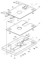
- FIG. 1 is an exploded view showing a configuration of a load detection device in the first embodiment
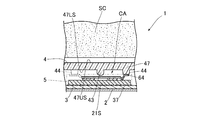
- FIG. 2 is a cross section showing a state in which the load detection device 1 is attached to an S spring of a seat device.
- FIG. FIG. 2 is a cross-sectional view of the load detection device 1 on a surface along the left-right direction of the seat device, and the load detection sensor 5 is simplified in order to avoid complication of the drawing.
- the load detection device 1 includes a pedestal 2 and a load detection sensor unit SU placed on the pedestal 2 as main components.
- the pedestal 2 has a placement portion 21 on which the load detection sensor unit SU is placed and a pair of hook portions 22 connected to the placement portion 21.
- the upper surface of the mounting portion 21 is a mounting surface 21S on which the load detection sensor unit SU is mounted. Further, the mounting portion 21 is formed with a plurality of through holes 23 penetrating from the mounting surface 21S to the lower surface of the mounting portion 21 (the surface opposite to the mounting surface 21S).
- the pedestal 2 is formed by molding a metal plate, for example, and in this case, the plate thickness is set to 0.8 mm, for example.
- the pair of hook portions 22 are locking portions for locking the base 2 to the S spring 100, and are provided at positions facing each other with the mounting portion 21 in between. These hook portions 22 are respectively fitted into a pair of adjacent S springs 100 among a plurality of S springs 100 stretched side by side in an opening of a frame in a vehicle seat device.
- the pair of hook portions 22 are formed so as to be fitted in a pair of S springs 100 arranged in the lateral direction of the seat device and adjacent in the lateral direction.
- the placement portion 21 is positioned below the seat cushion SC placed on the plurality of S springs 100, Further, when the plurality of S springs are viewed from above, the placing portion 21 is disposed between the pair of S springs 100. With the pair of hook portions 22 fitted into the pair of S springs 100 as described above, the placement surface 21S is positioned below the lower end of each S spring 100 in the present embodiment.
- the load detection sensor unit SU includes a housing 3, a housing cover 4, and a load detection sensor 5 as main components.
- the housing 3 has a connector part 31 connected to a vehicle control unit (not shown) and a sensor housing part 32 connected to the connector part 31.
- the sensor housing portion 32 has a bottom wall 37 and a frame wall 38, and a housing space CA for housing the load detection sensor 5 is formed by the bottom wall 37 and the frame wall 38.
- the frame wall 38 is subjected to a blanking process in order to suppress deformation during resin molding.
- a pair of fixing pins 33 and a pair of connection pins 34 are provided on the bottom wall 37 of the sensor housing portion 32.
- the pair of fixing pins 33 are pins for fixing the load detection sensor 5 accommodated in the housing 3.
- the pair of connection pins 34 are electrically connected to the connector terminals of the connector portion 31 and are also electrically connected to the load detection sensor 5 to electrically connect the connector terminals and the load detection sensor 5. It is a pin for. In FIG. 1, the connector terminals of the connector portion 31 are omitted.
- a pair of projecting pieces 35 are provided on the outer surface of the frame wall 38 of the sensor housing portion 32.
- the pair of protruding pieces 35 are provided so as to be arranged in the lateral direction of the seat.
- a plurality of hook pieces 36 that are fitted into the respective through holes 23 of the base 2 are provided at the lower end of the frame wall 38. The hook pieces 36 are fitted into the respective through holes 23 of the pedestal 2, whereby the housing 3 is fixed to the pedestal 2, and the load detection sensor unit SU is placed on the placement surface 21 ⁇ / b> S of the pedestal 2 as described above.
- the housing cover 4 is a pressing member that presses the load detection sensor 5 when pressed by the seat cushion SC.
- the housing cover 4 has a top wall 47 and a frame wall 48, and the accommodation space CA of the sensor housing portion 32 is covered by the top wall 47 and the frame wall 48.
- a pair of arms 41 is provided at the lower end of the frame wall 48 of the housing cover 4.
- Each arm 41 is formed with an opening 42 into which a protruding piece 35 provided on the frame wall 38 of the sensor housing portion 32 in the housing 3 is fitted.
- the housing cover 4 is locked to the housing 3 by fitting the pair of projecting pieces 35 of the housing 3 into the respective openings 42 of the pair of arms 41. That is, in a state where the housing cover 4 is locked to the housing 3, the pair of arms 41 sandwich the housing 3 from the lateral direction of the seat.
- the top wall 47 of the housing cover 4 is provided with a switch pressing portion 43 that protrudes from a lower surface 47LS that is a surface facing the bottom wall 37 of the sensor housing portion 32 in the housing 3.
- the tip of the switch pressing portion 43 has a convex curved surface.
- the tip of the switch pressing portion 43 is positioned above the switch of the load detection sensor 5.
- a gap GA is formed between the top wall 47 of the housing cover 4 and the frame wall 38 of the housing 3.
- the seat cushion SC is made of foamed urethane resin.
- the material of the housing cover 4 include resins such as polycarbonate (PC), polyimide (PI), polybutylene terephthalate (PBT), phenol resin, and epoxy resin.
- the upper surface 47US of the top wall 47 of the housing cover 4 faces the lower surface of the seat cushion SC with a predetermined distance therebetween.
- the upper surface 47US is a pressure receiving surface that receives pressure from the seat cushion SC. Note that the upper surface 47US of the top wall 47 of the housing cover 4 and the lower surface of the seat cushion SC may be in contact with each other.
- the top wall 47 of the housing cover 4 is larger than the switch of the load detection sensor 5 pressed by the switch pressing portion 43, and the switch pressing portion 43 is smaller than the switch of the load detection sensor 5.
- the switch of the load detection sensor 5 is positioned inside the range surrounded by the edge of the top surface 47S. Further, when the upper surface 47 ⁇ / b> S of the housing cover 4 is viewed from the front, the switch pressing portion 43 is located inside the range surrounded by the switch side surface of the load detection sensor 5.
- a first electrode 56e and a second electrode 57e which will be described later, are switches of the load detection sensor 5, and the side surfaces of the switches of the load detection sensor 5 are perpendicular to the thickness directions of the first electrode 56e and the second electrode 57e. It is a side surface of the electrode.
- a gap GA is formed between the top wall 47 of the housing cover 4 and the frame wall 38 of the housing 3.
- the housing cover 4 has an upper surface so that the angle of the upper surface 47US, which is a pressure receiving surface with respect to the mounting surface 21S, changes when viewed along the direction of the mounting surface 21S on which the load detection sensor unit SU is mounted.
- the entire 47US can move in the front-rear direction and the left-right direction with respect to the placement surface 21S.
- the pair of arms 41 of the housing cover 4 sandwich the housing 3 from the lateral direction of the seat device as described above, the angle at which the housing cover 4 rotates is larger in the front-rear direction than in the left-right direction of the seat.
- the upper surface 47US is not divided, the entire upper surface 47US moves.
- FIG. 3 is a diagram showing the relationship between the load and the angle of the lower surface of the seat cushion with respect to the horizontal plane when a person sitting on the seat device sits normally and when sitting in front.
- the angle of the lower surface of the seat cushion remains a change of less than 0.5 degrees forward and backward with respect to the initial state in the range of the load up to 500N. This tendency is considered to be the same even if the load exceeds 500 N as long as the person is seated normally.
- the angle of the lower surface of the seat cushion changes by about 5 degrees as compared with the initial state in the range of the load up to 500N.
- the moving angle of the housing cover 4 is 5 degrees or less.
- the upper surface 47US of the housing cover 4 also moves within 5 degrees.
- the angle of the lower surface of the cushion seat changes within a range of less than 0.5 degrees forward and backward with reference to the initial state in regular seating. Therefore, when the change in the inclination angle of the lower surface of the seat cushion is 0.5 degrees or more, there is a high possibility that the person sitting on the seat device is sitting in front.
- the upper surface 47US of the housing cover 4 also moves at 0.5 degrees or more with respect to the initial state, so that the upper surface 47US is inclined at least corresponding to at least part of the change in the inclination angle of the lower surface of the seat cushion due to the front seat. it can.
- the housing cover 4 has a pressure receiving surface so that the angle of the entire upper surface 47US, which is the pressure receiving surface, with respect to the mounting surface 21S changes when viewed along the direction of the mounting surface 21S on which the load detection sensor is mounted.
- the entire upper surface 47US moves relative to the placement surface 21S.
- the elastic support portion 64 (FIG. 1) constituting the load detection sensor 5 supports the housing cover 4 by lifting the housing cover 4.
- the portion where the elastic support portion 64 supports the housing cover 4 is located above the load detection sensor 5.
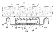
- FIG. 4 is a diagram illustrating a state in which the load detection sensor 5 supports the housing cover 4.
- FIG. 4 is a cross-sectional view of the load detection device 1 on a surface along the front-rear direction of the seat device.
- the load detection sensor 5 is simplified in FIG.
- the front end of the support base 44 has a planar shape, and the height from the lower surface 47LS to the front end of each support base 44 is lower than the height from the lower surface 47LS to the front end of the switch pressing portion 43. That is, the tip of each support base 44 is located above the tip of the switch pressing portion 43.
- the housing cover 4 In a state in which the housing cover 4 covers the housing 3 and the protruding pieces 35 are fitted in the respective openings 42, the tips of the support bases 44 abut against a part of the elastic support portion 64 of the load detection sensor 5.
- the housing cover 4 is supported by the support portion 64.
- the housing cover 4 moves as a whole with respect to the mounting surface 21S so that the angle of the entire upper surface 47US with respect to the mounting surface 21S on which the load detection sensor is mounted changes as described above.
- the load detection sensor 5 moves the housing cover 4 in a state where the entire upper surface 47US moves with respect to the placement surface 21S so that the angle of the entire upper surface 47US with respect to the placement surface 21S on which the load detection sensor is placed changes. It has the elastic support part 64 to support.
- FIG. 5 is an exploded view showing the configuration of the load detection sensor 5.
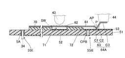
- 6 is a sectional view taken along line XX of the load detection sensor 5 shown in FIG. 5
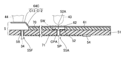
- FIG. 7 is a sectional view taken along line YY of the load detection sensor 5 shown in FIG.
- the load detection sensor 5 includes a first electrode sheet 50, a second electrode sheet 60, and a spacer 70 as main components.
- the first electrode sheet 50 includes, for example, an insulating substrate 51 that does not have flexibility.
- Examples of the material of the substrate 51 include phenol resin and epoxy resin.
- the first electrode 52 and the first contact portion 53 are disposed on one surface F1 of the substrate 51 that faces the second electrode sheet 60.
- the first electrode 52 is one electrode constituting the switch SW, and is, for example, a circular metal printing layer.
- the first contact portion 53 is formed by connecting a substantially rectangular contact area AR1 that is in contact with the second electrode sheet 60 and a non-contact area AR2 that is not in contact with the second electrode sheet 60 to each other.
- the other surface F2 opposite to the one surface F1 is a lower surface of the load detection sensor 5, and a resistor 54 is disposed on the other surface F2.
- the resistor 54 is a resistor for detecting disconnection.
- the resistor 54 is constituted by a chip resistor.
- the substrate 51 is formed with a plurality of through holes penetrating from one surface F1 to the other surface F2 of the substrate 51.
- the first sheet through hole 55 ⁇ / b> A is a sheet through hole in which an opening is located in a region where the first electrode 52 is disposed on one surface F ⁇ b> 1 of the substrate 51.
- a first conductive member CPA is provided in the first sheet through hole 55A, and the circuit portion and the first electrode 52 arranged on the other surface F2 of the substrate 51 via the first conductive member CPA. Are electrically connected. Thereby, the first conductive member CPA and the resistor 54 are electrically connected, and as a result, the first electrode 52 and the resistor 54 are electrically connected.
- the first conductive member CPA is provided on the inner peripheral surface of the first sheet through hole 55A, and an air hole SP surrounded by the first conductive member CPA is provided in the first sheet through hole 55A. It is formed.
- the second sheet through hole 55B is a sheet through hole in which an opening is located in a region where the first contact portion 53 is disposed on one surface F1 of the substrate 51.
- the opening of the second sheet through hole 55B is positioned in the non-contact area AR2 of the first contact portion 53.
- the second conductive member CPB is filled in the second sheet through hole 55B. Via this second conductive member CPB, the circuit part disposed on the other surface F2 of the substrate 51 and the non-contact area AR2 of the first contact portion 53 are electrically connected, and the other surface F2 of the substrate 51 is connected. , The second conductive member CPB is connected to the resistor 54. Therefore, the resistor 54 and the first contact portion 53 are electrically connected. Since the first electrode 52 and the resistor 54 are electrically connected as described above, the first electrode 52, the resistor 54, and the first contact portion 53 are electrically connected in series in this order.
- the fixing through holes 55 ⁇ / b> C and 55 ⁇ / b> D are through holes through which a pair of fixing pins 33 provided on the bottom wall 37 of the sensor housing portion in the housing 3 are inserted.
- the diameters of the fixing through holes 55 ⁇ / b> C and 55 ⁇ / b> D are approximately the same as the outer diameter of the pair of fixing pins 33.
- the pin through holes 55E and 55F are through holes through which a pair of connection pins 34 provided in the housing 3 are inserted.
- a terminal 5A which is one end portion of the electric circuit in the load detection sensor 5, is provided inside the pin through hole 55E, and the other end portion of the electric circuit in the load detection sensor 5 is provided in the pin through hole 55F.
- a terminal 5B is provided. The terminal 5A is electrically connected to the contact point between the first electrode 52 and the resistor 54, and the terminal 5B is electrically connected to the contact point between the resistor 54 and the first contact part 53.
- the terminals 5A and 5B are provided along the inner peripheral surfaces of the corresponding pin through holes 55E and 55F, and the width of the space surrounded by the terminals 5A and 5B is approximately the same as the outer diameter of the connection pin 34. It is said. When the pair of pin through holes 55E and 55F is inserted, the terminal 5A and one connection pin 34 are electrically connected, and the terminal 5B and the other connection pin 34 are electrically connected.
- the second electrode sheet 60 mainly includes a metal plate 61, a second electrode 62, a second contact portion 63, and an elastic support portion 64 (64A to 64C).
- the metal plate 61 is a thin metal plate having flexibility.
- the metal plate 61 has a vertical width shorter than the vertical width of the substrate 51, and is a thin, substantially rectangular parallelepiped having a horizontal width equal to the horizontal width of the substrate 51. It is made into a shape.
- the material of the metal plate 61 is not particularly limited as long as it is a metal, and examples thereof include copper and stainless steel.
- the metal plate 61 is formed with fixing through holes 65C and 65D penetrating from one surface of the metal plate 61 to the other surface.
- the fixing through holes 65 ⁇ / b> C and 65 ⁇ / b> D are through holes through which a pair of fixing pins 33 provided on the bottom wall of the sensor housing portion in the housing 3 are inserted, and are formed in the substrate 51 of the first electrode sheet 50. It has the same shape and size as the holes 55C and 55D. Further, the arrangement positions of the second electrode 62 and the second contact portion 63 with respect to the fixing through holes 65C and 65D, and the first electrode 52 and the first contact portion 53 with respect to the fixing through holes 55C and 55D in the first electrode sheet 50 are provided. When the first electrode sheet 50 and the metal plate 61 are overlapped with each other, the fixing through hole 55C and the fixing through hole 65C overlap each other, and the fixing through hole 55D The fixing through holes 65D overlap each other.
- the second electrode 62 is the other electrode constituting the switch SW.
- the second electrode 62 is a portion facing the first electrode 52 through the spacer 70 in the metal plate 61. That is, a part of the metal plate 61 also serves as the second electrode 62.
- a metal layer made of the same material as or different from that of the metal plate 61 may be disposed as a second electrode 62 at a portion of the metal plate 61 that faces the first electrode 52 via the spacer 70.
- the second contact part 63 is one member constituting the connection maintaining part AP, and is formed as a leaf spring in the present embodiment. That is, the metal plate 61 is provided with a pair of notches 61A and 61B (FIG. 1) extending from one end on the short side to the other end side of the metal plate 61 with a predetermined interval therebetween. A belt-like portion sandwiched between 61A and 61B (FIG. 1) is the second contact portion 63. Further, the second contact portion 63 is bent so that the cross section along the thickness direction of the metal plate 61 is V-shaped.
- the second contact part 63 is moved away from the turning point P, and the spring piece C1 extending inclined from the turning point P located on the first electrode sheet 50 side toward the root side of the second contact part 63. Accordingly, it has a spring piece C2 that is inclined so as to be separated from the spring piece C1 and extends to the distal end side of the second contact portion 63.
- the turning point P is a portion that contacts the first contact portion 53 of the first electrode sheet 50.
- a portion of the metal plate 61 that is different from the portion that is the second electrode 62 is the second contact portion 63.
- the position where the second contact portion 63 is formed is a position that overlaps the contact area AR1 of the first contact portion 53 when the first electrode sheet 50 and the second electrode sheet 60 are overlapped.
- the shape of the leaf spring formed as the second contact portion 63 may be, for example, a trapezoid whose base width is larger than the width of the open end, and various shapes other than a rectangle and a trapezoid are applicable. is there.
- a metal layer made of the same material as or different from the metal plate 61 may be disposed on the first electrode sheet 50 side in the metal plate 61.
- the elastic support portion 64 is a member that supports the housing cover 4 and has elasticity.
- the elastic support portion 64 supports the housing cover 4 at three locations. That is, in the present embodiment, the elastic support portion 64A located on one short side of the metal plate 61, and the virtual straight line LN passing through the longitudinal direction of the elastic support portion 64A on the other short side of the metal plate 61 (see FIG. A pair of elastic support portions 64B and 64C are provided so as to sandwich 1).
- the elastic support portion 64A is a portion that supports one portion of the housing cover 4 and is formed as a leaf spring using the second contact portion 63 as a part. That is, the elastic support portion 64 ⁇ / b> A includes the spring pieces C ⁇ b> 1 and the spring pieces C ⁇ b> 2 in the second contact portion 63, and a placing piece C ⁇ b> 3 extending from the spring pieces C ⁇ b> 2 substantially parallel to the sheet surface of the metal plate 61.
- the placement piece C3 is positioned higher than the sheet surface of the metal plate main body and is a portion on which one of the plurality of support bases 44 provided on the lower surface 47LS of the housing cover 4 is placed.
- the metal plate main body is a portion of the metal plate 61 other than the second contact portion 63 and the elastic support portion 64 (64A to 64C).
- the elastic support portions 64B and 64C are portions that support two locations opposite to the elastic support portion 64A with respect to the metal plate body, and are formed as leaf springs.
- the elastic support portions 64B and 64C include a spring piece C12 that is inclined and extends from the metal plate main body, and a mounting piece C13 that extends from the spring piece C12 to be substantially parallel to the sheet surface of the metal plate 61.
- the placement piece C13 has the same height as the placement piece C3, and is a portion on which one of the plurality of support bases 44 provided on the lower surface 47LS of the housing cover 4 is placed.
- the spacer 70 is a thin insulating member that is sandwiched between the first electrode sheet 50 and the second electrode sheet 60.
- the spacer 70 has substantially the same shape as that obtained by removing the second contact portion 63 from the metal plate 61.
- the material of the spacer 70 include resins such as PET, PBT, and PEN.
- An opening 71 is formed in the spacer 70.
- the opening 71 is between the first electrode 52 disposed on the substrate 51 and the second electrode 62 of the metal plate 61 facing the first electrode 52, and the first electrode 52 and the second electrode 62 in the vertical direction. It is formed at a position overlapping the two electrodes 62.
- the size of the opening 71 is slightly smaller than the size of the first electrode 52.
- a slit-like opening 72 is formed in the spacer 70.
- the opening 72 is between the first contact portion 53 disposed on the substrate 51 and the second contact portion 63 of the metal plate 61 facing the first contact portion 53, and is the first contact in the vertical direction. It is formed at a position overlapping the portion 53 and the second contact portion 63.
- the size of the opening 72 is slightly larger than the size of the leaf spring formed as the second contact portion 63 in the metal plate 61.
- the spacer 70 is formed with fixing through holes 75C and 75D penetrating from one surface of the spacer 70 to the other surface.
- the fixing through holes 75C and 75D are through holes into which the fixing pins 33 provided on the bottom wall of the sensor housing portion in the housing 3 are inserted, and the fixing through holes 55C formed in the substrate 51 of the first electrode sheet 50. , 55D.
- the fixing through hole 55C, the fixing through hole 65C, and the fixing through hole 75C are overlapped with each other, and the fixing through hole 55D is fixed.
- the through hole 65D and the fixing through hole 75C overlap each other.
- the first electrode sheet 50, the second electrode sheet 60, and the spacer 70 are overlapped to constitute the load detection sensor 5.
- the first electrode 52 and the second electrode 62 face each other through the opening 71 to form a switch SW.
- the distance between the first electrode 52 and the second electrode 62 is, for example, 0.1 mm.
- the air hole SP formed in the electrode through hole 52 ⁇ / b> A communicates with the opening 71. Therefore, when the second electrode 62 is bent and contacts the first electrode 52, unnecessary air can be discharged from the air hole SP to the outside of the load detection sensor 5.
- the first sheet through hole 55A is only a hole for electrically connecting the first electrode 52 disposed on the one surface F1 of the substrate 51 and the circuit portion disposed on the other surface F2 side. It also serves as an exhaust hole for discharging the air in the opening 71 to the outside of the load detection sensor 5.
- the second contact portion 63 of the second electrode sheet 60 is formed as a leaf spring, and is plastically deformed with respect to the sheet surface of the metal plate body so as to be always inclined. is there. Therefore, as shown in FIG. 7, the second contact portion 63 passes through the opening 72 formed by the notch of the spacer 70 and is connected to the contact area AR ⁇ b> 1 of the first contact portion 53 of the first electrode sheet 50.
- the connection maintaining part AP is formed by the first contact part 53 and the second contact part 63 coming into contact with each other.
- the first contact portion 53 of the first electrode sheet 50 is one member constituting the connection maintaining portion AP that maintains the electrical connection even when no external pressure is applied to the housing cover 4 of the load detection sensor unit SU.
- the second contact portion 63 of the second electrode sheet 60 is the other member constituting the connection maintaining portion AP.
- the elastic support portion 64 of the second electrode sheet 60 is formed as a leaf spring, and is always inclined to the side opposite to the side where the second contact portion 63 is inclined with respect to the metal plate main body. It is in. For this reason, as shown in FIG. 4, when the load detection sensor 5 is arranged in the housing space CA of the housing 3 and the housing cover 4 is attached to the housing 3, the elastic support portion 64 includes the support bases of the housing cover 4. The housing cover 4 is supported at three locations so as to lift 44. As described above, the housing cover 4 has the entire upper surface 47US so that the angle of the upper surface 47US with respect to the placement surface 21S changes when viewed along the direction of the placement surface 21S on which the load detection sensor 5 is placed.
- the elastic support part 64 supports the housing cover 4 in a state where the entire upper surface 47US moves relative to the placement surface 21S so that the angle of the upper surface 47US with respect to the placement surface 21S changes.
- the pair of fixing pins 33 in the housing 3 are fixed through holes 55 ⁇ / b> C and 55 ⁇ / b> D in the first electrode sheet 50, and fixed through holes 75 ⁇ / b> C and 75 ⁇ / b> D in the spacer 70. And it is fixed to the housing 3 by being inserted through the fixing through holes 65C and 65D of the second electrode sheet 60 in order. At this time, the substrate 51 and the bottom wall 37 of the housing 3 are located between the first electrode 52 and the mounting surface 21 ⁇ / b> S of the base 2. Further, in a state where the load detection sensor 5 is fixed to the housing 3 and the housing 3 is placed on the pedestal 2, the first electrode 52 and the second electrode 62 are respectively S springs 100 to which the pedestal 2 is locked. It is located below the lower end of.
- the pair of connection pins 34 are inserted into the pin through holes 55E and 55F of the first electrode sheet 50, respectively.
- the terminals 5A and 5B provided in the pin through holes 55E and 55F come into contact with the corresponding connection pins 34 and are electrically connected to the connector terminals of the connector portion 31 of the housing 3 via the connection pins 34.
- the support base 44 of the housing cover 4 contacts the elastic support part 64 of the load detection sensor 5 by attaching the housing cover 4.
- the elastic support portion 64 supports the housing cover 4 in a state where the entire upper surface 47US moves relative to the mounting surface 21S so that the angle of the upper surface 47US with respect to the mounting surface 21S changes.
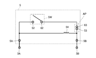
- FIG. 8 is a diagram showing an equivalent circuit of the load detection sensor 5 fixed to the housing 3.
- a switch SW first electrode 52 and second electrode 62
- a connection maintaining unit AP first contact point
- the switch SW is electrically connected between the pair of terminals 5A and 5B, and is connected to connector terminals 3A and 3B provided on the connector portion 31 of the housing 3 via the pair of terminals 5A and 5B. Since the resistor 54 is electrically connected to the first electrode 52 and the first contact portion 53 as described above, the resistor 54 is electrically connected to the switch SW in parallel. Therefore, when the switch SW is turned on, the resistance value between the terminals 5A and 5B is lower than when the switch SW is turned off.
- the lower surface of the seat cushion SC moves downward due to the load of the person.
- the lower surface of the seat cushion SC may be inclined with respect to the S spring surfaces including the respective S springs 100 due to human load.
- the lower surface of the seat cushion SC contacts the upper ends of the pair of hook portions 22. Therefore, even if the lower surface of the seat cushion SC is inclined with respect to the S spring surface as described above, the upper ends of the pair of hook portions 22 press the lower surface of the seat cushion SC, so The slope is relaxed to some extent.
- the lower surface of the seat cushion SC moves downward, the lower surface of the seat cushion SC comes into contact with the upper surface 47US of the housing cover 4 while being deformed by being pressed by the upper ends of the pair of hook portions 22.
- the lower surface of the seat cushion SC may be inclined to some extent while the inclination is relaxed as described above.
- the lower surface of the seat cushion SC is also inclined with respect to the mounting surface 21S of the base 2 locked to the S spring 100, and the housing of the load detection sensor unit SU fixed on the mounting surface 21S.
- the lower surface of the seat cushion SC is also inclined with respect to the upper surface 47US of the cover 4.
- the housing cover 4 can follow the seat cushion SC. It moves so that the angle with respect to the mounting surface 21S changes. Therefore, the upper surface 47US of the housing cover 4 can come into surface contact with the lower surface of the seat cushion SC.
- the gap GA is formed between the housing cover 4 and the housing 3. For this reason, when the lower surface of the seat cushion SC further moves downward, the elastic support portions 64 (64A to 64C) of the load detection sensor 5 supporting the housing cover 4 are bent downward, and the housing cover 4 has the gap GA. Move downward within range.
- FIG. 9 is a diagram illustrating an ON state of the load detection sensor 5. Due to the downward movement of the housing cover 4, the tip of the switch pressing portion 43 presses the second electrode 62, and as shown in FIG. 9, the second electrode 62 contacts the first electrode 52 and the load detection sensor 5. The switch SW is turned on. For this reason, the resistance value between the pair of terminals 5A and 5B becomes low, and the change in resistance is detected by the vehicle control unit (not shown) via the connector terminals 3A and 3B. Thus, the load applied according to the seating is detected.
- the load detection device 1 has the load detection sensor 5 and the upper surface 47US that is a pressure receiving surface that receives pressure from the seat cushion SC of the seat device, and the upper surface 47US corresponds to the seat cushion SC.
- a housing cover 4 as a pressing member that presses the load detection sensor 5 when pressed, and an elastic support portion 64 that supports the housing cover 4 from the load detection sensor 5 side are provided.
- the movement when the housing cover 4 presses the load detection sensor 5 in accordance with the press from the seat cushion SC is alleviated. Accordingly, even if the housing cover 4 may come into contact with another member according to the movement of the housing cover 4, the impact of the housing cover 4 on the other member is reduced, and as a result, abnormal noise can be suppressed.
- the load detection device 1 of the present embodiment can appropriately detect the load while suppressing the generation of abnormal noise.
- the angle of the upper surface 47US of the housing cover 4 that is a pressure receiving surface pressed against the seat cushion SC with respect to the mounting surface 21S of the base 2 changes. For this reason, even when the degree of inclination of the lower surface of the seat cushion SC changes and descends, the upper surface 47US can follow the inclination. Accordingly, the upper surface 47US is pressed in appropriate surface contact with the lower surface of the seat cushion SC. Therefore, according to the load detection apparatus 1 of this embodiment, a load can be detected appropriately.
- the load detection sensor 5 includes the first electrode sheet 50 including at least one or more first electrodes 52, and the housing cover 4 (switch pressing portion 43) than the first electrode sheet 50. ) Side, the second electrode sheet 60 including the second electrode 62 facing the first electrode 52, and the first electrode sheet 50 and the second electrode sheet 60, and at least the first electrode 52 and And a spacer 70 provided with an opening 71 between the second electrodes 62. A part of the second electrode sheet 60 is an elastic support part 64.
- the load detection device 1 can be reduced in size and space.
- the second electrode sheet 60 includes a metal plate 61 on the housing cover 4 (switch pressing portion 43) side, and a part of the metal plate 61 serves as an elastic support portion 64. ing.
- the second electrode sheet 60 includes the metal plate 61 on the housing cover 4 (switch pressing portion 43) side, so that the flexibility does not easily change even when the temperature changes. Therefore, even when the environmental temperature around the load detection device 1 changes, the bending method of the metal plate 61 pressed by the switch pressing portion 43 is not so likely to change. In addition, since a part of the metal plate 61 is the elastic support portion 64, even when the environmental temperature around the load detection device 1 changes, the elastic force of the elastic support portion 64 hardly changes. Therefore, according to this load detection apparatus 1, even if the environmental temperature changes, erroneous detection such as seating can be suppressed.
- the second electrode sheet 60 of the load detection sensor 5 is made of a metal plate 61.
- a portion of the metal plate 61 that faces the first electrode 52 through the opening 71 of the spacer 70 is a second electrode 62, and another portion of the metal plate 61 is an elastic support portion 64.
- the metal plate 61 plays a role as an electrode constituting one of the switches SW and a role as a support portion for supporting the housing cover 4. Therefore, the load detection device 1 according to the present embodiment can appropriately detect the load while suppressing the generation of abnormal noise while suppressing the number of parts of the load detection sensor 5.
- connection maintaining unit AP is configured that maintains electrical connection even when external pressure is not applied between a part of the first electrode sheet 50 and a part of the second electrode sheet 60. Is done.
- the circuit formed on the first electrode sheet 50 and the circuit formed on the second electrode sheet 60 are always in a conductive state via the connection maintaining part AP. Therefore, even when the series number of switches SW connected in series in the circuit in the load detection sensor 5 is an odd number, in the load detection sensor 5, the pair of terminals 5 ⁇ / b> A and 5 ⁇ / b> B of the circuit are arranged only in the first electrode sheet 50. be able to.
- a part of the metal plate 61 constituting the connection maintaining part AP also serves as the elastic support part 64A.
- a force acts on the elastic support portion 64A as a repulsive force on the first electrode sheet 50 side, and a force acts on a part of the second electrode sheet 60 constituting the connection maintaining portion AP on the first electrode sheet 50 side. . Therefore, the connection state of the connection maintaining unit AP can be made stronger.
- the metal plate 61 plays a role of arranging the pair of terminals 5 ⁇ / b> A and 5 ⁇ / b> B on the first electrode sheet 50 and a role as a support portion for supporting the housing cover 4. For this reason, it is possible to appropriately detect the load while suppressing the generation of abnormal noise while further suppressing the number of parts of the load detection sensor 5.
- the portion where the elastic support portion 64 supports the housing cover 4 is located above the load detection sensor 5. For this reason, it becomes possible to achieve size reduction as compared with the case where the elastic support portion supports the pressing member below the load detection sensor 5.
- the 2nd electrode sheet 60 consists of the metal plate 61 as mentioned above. For this reason, since there is little influence by the heat in the 2nd electrode sheet 60, even if it uses in high temperature environment or a low temperature environment, the sensitivity of the load detection sensor 5 is stabilized. Moreover, since the 2nd electrode sheet 60 is a metal, damage etc. can be reduced and durability can be improved. Furthermore, since the second contact portion 63 that is a leaf spring in the second electrode sheet 60 is also a metal, the second contact formed as the leaf spring is compared with a case where a part of the resin sheet is a leaf spring. The malleability and ductility of the part 63 can be increased. Accordingly, it is possible to reduce breakage such as breakage of the second contact portion 63 formed as a leaf spring and improve the durability of the leaf spring.
- the substrate 51 serving as the sheet of the first electrode sheet 50 penetrates from one surface F1 facing the second electrode sheet 60 to the other surface F2. It has a through hole 55A. Further, the first electrode 52 is electrically connected to a circuit portion disposed on the other surface F2 of the substrate 51 through a first conductive member CPA provided in the first sheet through hole 55A. For this reason, it becomes possible to take out one terminal 5A to the other surface F2 of the board
- circuit part can be provided on the other surface F2, it is not necessary to provide the circuit part on the one surface F1, and unevenness due to the circuit part on the one surface F1 can be reduced. Thereby, the sensitivity of the load detection sensor 5 can be stabilized.
- the opening on the one surface side of the first sheet through hole 55A is located in the region where the first electrode 52 is disposed on the one surface F1 of the substrate 51.
- the first sheet through hole 55 ⁇ / b> A has an air hole SP that communicates with the opening 71 between the first electrode 52 and the second electrode 62 via the electrode through hole 52 ⁇ / b> A provided in the first electrode 52.
- the first sheet through-hole 55 ⁇ / b> A is a connection hole for electrically connecting the first electrode 52 disposed on the one surface F ⁇ b> 1 of the substrate 51 to the circuit portion on the other surface side of the substrate 51.
- it also serves as an exhaust hole for discharging the spacer air to the outside. For this reason, durability of the board
- substrate 51 can be improved compared with the case where a connection hole and an exhaust hole are provided separately. Further, it is not necessary to provide a separate exhaust hole, and space can be saved.
- the substrate 51 serving as the sheet of the first electrode sheet 50 is located at a position different from the first sheet through-hole 55A from one surface F1 facing the second electrode sheet 60. It has the 2nd sheet penetration hole 55B which penetrates to the other field F2. Further, the first contact portion 53 is electrically connected to a circuit portion disposed on the other surface F2 of the substrate 51 through a second conductive member CPB provided in the second sheet through hole 55B. For this reason, the pair of terminals 5A and 5B can be taken out from the other surface F2 of the substrate 51. As in the present embodiment, the terminals 5A and 5B can be arranged inside the pin through holes 55E and 55F different from the first sheet through hole 55A.
- the circuit part can be provided on the other surface F2, it is not necessary to provide the circuit part on the one surface F1, and unevenness due to the circuit part on the one surface F1 can be reduced. Thereby, the sensitivity of the load detection sensor 5 can be stabilized.
- the load detection sensor 5 of the present embodiment has a resistor 54 that is disposed on the other surface F2 of the substrate 51 and connects the first electrode 52 and the first contact portion 53. For this reason, even if the thickness of the resistor 54 is large, it can be avoided that the sensitivity of the load detection device 1 is deteriorated due to the thickness.
- the circuit portion and the resistor 54 in the first electrode sheet 50 are provided on the other surface F2 of the substrate 51, and the pair of terminals 5A and 5B are provided in the pin through holes 55E and 55F. .
- components other than the 1st electrode 52 and the 1st contact part 53 can be excluded from one surface F1 of the board
- FIG. Therefore, the unevenness
- the metal plate 61 of the second electrode sheet 60 constituting the load detection sensor 5 is different from the load detection device 1 in the first embodiment. That is, the metal plate 61 in the first embodiment employs elastic support portions 64A to 64C that support the housing cover 4 at three locations. On the other hand, in this embodiment, the elastic support part which supports the housing cover 4 in two places is employ
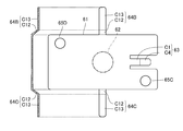
- FIG. 10 is a view and a cross-sectional view of the metal plate 61 of the load detection sensor according to the second embodiment as viewed from the upper surface side.
- the load detection sensor of the present embodiment supports the housing cover 4 by a pair of elastic support portions 64B and 64C that are different in arrangement position from the first embodiment.
- the elastic support portion 64B of the present embodiment is disposed so as to extend from an intermediate portion on one long side of the metal plate 61. Further, the elastic support portion 64 ⁇ / b> C is disposed so as to extend from an intermediate portion on the other long side of the metal plate 61.
- the elastic support portion 64A of the first embodiment formed by using the second contact portion 63 as a part is omitted, and the shape of the second contact portion 63 of the present embodiment is changed.
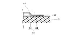
- the second contact portion 63 of the present embodiment includes a spring piece C ⁇ b> 1 and a spring piece C ⁇ b> 1 extending substantially parallel to the sheet surface of the metal plate 61. It consists of a contact piece C4.
- the contact piece C ⁇ b> 4 is a portion that contacts the first contact portion 53 of the first electrode sheet 50.
- the number and arrangement positions of the support bases 44 of the housing cover 4 are changed.
- the number of the support bases 44 in this embodiment is two, and is provided at a position corresponding to the pair of elastic support portions 64B and 64C.
- the support base 44 is arranged so as to come into contact with the mounting pieces C13 of the pair of elastic support portions 64B and 64C in the load detection sensor 5. Is done.
- the movement of the upper surface 47US, which is the pressure receiving surface of the housing cover 4, following the inclination of the bottom surface of the seat cushion SC is alleviated. Therefore, even if the housing cover 4 may come into contact with another member such as the frame wall 38 of the housing 3 according to the movement of the housing cover 4, the impact of the housing cover 4 on the other member is reduced. Can be suppressed.
- the metal plate 61 of the second electrode sheet 60 constituting the load detection sensor 5 is different from the load detection device 1 in the first embodiment. That is, in the metal plate 61 in the first embodiment, the elastic support portion 64 that supports the housing cover 4 at three locations is employed. On the other hand, in this embodiment, the elastic support part which supports the housing cover 4 in two places is employ
- FIG. 12 is a diagram showing a cross section of the metal plate 61 of the load detection sensor according to the second embodiment as viewed from the upper surface side.
- the load detection sensor of the present embodiment supports the housing cover 4 by a pair of elastic support portions 64B and 64C that are different from the first embodiment in the arrangement position.
- the elastic support portion 64B of the present embodiment is disposed so as to extend from the end portion on the short side where the second contact portion 63 is provided in the metal plate 61. Further, the elastic support portion 64C is disposed on the other short side of the metal plate 61 so as to extend from an end portion that is diagonally opposite to the elastic support portion 64B.
- the elastic support portion 64A of the first embodiment formed by using the second contact portion 63 as a part is omitted, and the second contact portion 63 of the present embodiment is, for example, a spring piece shown in FIG. C1 and contact piece C4 are comprised.
- the number and arrangement positions of the support bases 44 of the housing cover 4 are changed.
- the number of the support bases 44 in this embodiment is two, and is provided at a position corresponding to the pair of elastic support portions 64B and 64C.
- the support base 44 is arranged so as to come into contact with the mounting pieces C13 of the pair of elastic support portions 64B and 64C in the load detection sensor 5. Is done.
- the movement of the upper surface 47US, which is the pressure receiving surface of the housing cover 4, following the inclination of the bottom surface of the seat cushion SC is alleviated. Therefore, even if the housing cover 4 may come into contact with another member such as the frame wall 38 of the housing 3 according to the movement of the housing cover 4, the impact of the housing cover 4 on the other member is reduced. Can be suppressed.
- the metal plate 61 of the second electrode sheet 60 constituting the load detection sensor 5 is different from the load detection device 1 in the first embodiment. That is, in the metal plate 61 in the first embodiment, the elastic support portion 64 that supports the housing cover 4 at three locations is employed. On the other hand, in this embodiment, the elastic support part 64 which supports the housing cover 4 in one place is employ
- FIG. 13 is a diagram showing the load detection device in the fourth embodiment from the same viewpoint as FIG. 4, and FIG. 14 is a diagram showing the load detection device in the fourth embodiment from the same viewpoint as in FIG.
- the pair of elastic support portions 64B and 64C is omitted, and only the elastic support portion 64A is left. Therefore, as shown in FIG. 14, the switch pressing portion 43 is used as a reference and formed between the top wall 47 of the housing cover 4 and the frame wall 38 of the housing 3 on the side opposite to the elastic support portion 64 ⁇ / b> A side.
- the gap GA disappears, the top wall 47 and the frame wall 38 come into contact with each other, and a part of the housing cover 4 is supported by the frame wall 38.
- the movement of the upper surface 47US, which is the pressure receiving surface of the housing cover 4, following the inclination of the bottom surface of the seat cushion SC is alleviated. Therefore, even if the housing cover 4 may come into contact with another member such as the frame wall 38 of the housing 3 according to the movement of the housing cover 4, the impact of the housing cover 4 on the other member is reduced. Can be suppressed.
- the entire housing cover 4 is supported, It is preferable that the top wall 47 of the housing cover 4 and the frame wall 38 of the housing 3 are not in contact with each other.
- FIG. 15 is a diagram showing the load detection device in the fifth embodiment from the same viewpoint as in FIG. 2, and FIG. 16 is a diagram showing the configuration of the load detection sensor 5 in the fifth embodiment from the same viewpoint as in FIG. .
- the load detection sensor unit SU is configured by the housing 3, the housing cover 4, the load detection sensor 5, and the plate-like member 67 made of metal as an elastic support portion, and the load detection sensor unit SU
- the pedestal 2 constitutes the load detection device 1.
- the slit-shaped opening 72 is omitted, and a slit SR for air removal is provided.
- the 1st electrode sheet 50 in this embodiment it replaces with the board
- the insulating sheet 56 includes a sheet main body 56A and a terminal arrangement portion 56B protruding from the sheet main body.
- a plate-like terminal 5A is arranged on the same surface as the surface on which the first electrode 52 is provided in the sheet main body 56A.
- the terminal 5A is connected to the first electrode 52 via a wire and electrically connected to the connector terminal of the connector portion 31 via a lead wire or the like.
- the connection pins 34 are also omitted as with the fixing pins 33.
- resin such as PET, PBT, or PEN, is mentioned.
- the first contact portion 53, the first sheet through hole 55A, the second sheet through hole 55B, the fixing through holes 55C and 55D, and the pin through holes 55E and 55F are omitted.
- the insulating sheet 66 includes a sheet main body 66A and a terminal arrangement portion 66B protruding from the sheet main body.
- the terminal arrangement portion 66B is provided so as not to overlap with the terminal arrangement portion 56B in a direction orthogonal to the sheet surface, and the terminal arrangement portion 66B has a surface on which the second electrode 62 is provided in the sheet main body 66A.
- a plate-like terminal 5B is disposed on the same surface.
- the terminal 5B is connected to the second electrode 62 via a wire and electrically connected to the connector terminal of the connector portion 31 via a lead wire or the like.
- resin such as PET, PBT, or PEN, is mentioned.
- the second contact part 63 and the fixing through holes 65C and 65D are omitted.
- the load detection sensor 5 of the present embodiment does not have the connection maintaining unit AP and has a so-called membrane switch configuration.
- the elastic support part 64 formed in a part of the said metal plate 61 is lose
- a plate-like member 67 made of metal as an elastic support portion is newly provided. That is, in the present embodiment, a plate-like member 67 as an elastic support portion is provided separately from the load detection sensor 5.
- the plate-like member 67 is not fixed to the insulating sheet 66 but is fixed to the housing 3. As shown in FIG. 15, in the present embodiment, a pair of ribs 39 are provided at positions surrounded by the frame wall 38. The distance between the ribs 39 is smaller than the length of the plate member 67, and both ends of the plate member 67 are fixed to these ribs 39. Thereby, the plate-shaped member 67 is curved in an arch shape toward the housing cover 4 side which is a pressing member. The plate-like member 67 is larger than the pair of insulating sheets 56 and 66.
- a through hole 68 through which the switch pressing portion 43 is inserted is provided at a portion including a position where the bending rate is highest in the plate member 67.
- the switch pressing portion 43 passes through the through hole 68 of the plate member 67, and the tip of the switch pressing portion 43 is positioned between the plate member 67 and the insulating sheet 66.
- the plate-like member 67 supports the housing cover 4 in a state where the entire upper surface 47US moves with respect to the mounting surface 21S so that the angle of the upper surface 47US with respect to the mounting surface 21S changes. That is, the entire plate-like member 67 is an elastic support portion.
- the movement of the upper surface 47US, which is the pressure receiving surface of the housing cover 4, following the inclination of the bottom surface of the seat cushion SC is alleviated. Therefore, even if the housing cover 4 may come into contact with another member such as the frame wall 38 of the housing 3 according to the movement of the housing cover 4, the impact of the housing cover 4 on the other member is reduced. Can be suppressed.
- the plate-like member 67 of the present embodiment is provided between the load detection sensor 5 and the housing cover 4 (switch pressing portion 43) as a pressing member, and is made of metal.
- the plate member 67 is curved in an arch shape toward the housing cover 4 side, and the entire plate member 67 is an elastic support portion.
- the housing cover 4 that presses the load detection sensor 5 by being pressed by the seat cushion SC is supported by a plate-like member 67 that curves in an arch shape toward the housing cover 4 side.
- the change in the load applied from the housing cover 4 to the load detection sensor 5 is likely to depend on the plate-like member 67 that supports the housing cover 4.
- the plate-like member 67 is made of metal, it is difficult to reduce deterioration as compared with the case of being made of resin or the like. Therefore, even if the housing cover 4 is continuously pressed from the seat cushion SC for a long period of time, the change in the load applied to the load detection sensor 5 from the housing cover 4 by the plate member 67 can be reduced. As a result, the load can be detected appropriately.
- the plate-like member 67 supports the housing cover 4 as a whole, it is easier to support the housing cover 4 more stably than when the housing cover 4 is supported by a part of the plate-like member 67. it can.
- the material of the plate-like member 67 is made of metal, but is preferably made of bimetal that is deformed so as to be separated from the insulating sheet 66 as the temperature rises.
- the electrode is formed on the resin insulating sheet 66 as in this embodiment, the insulating sheet 66 is likely to be deformed as the temperature rises, and the switch SW is easily turned on with a weak force as the temperature rises. Become. Metals do not change flexibility even when the temperature changes, but the flexibility does not change at all.
- the plate-like member 67 is formed of a bimetal that is deformed so as to be separated from the insulating sheet 66 as the temperature rises, so that when the temperature rises, the insulating sheet 66 can be easily bent or the switch SW with a weak force. It is possible to prevent the load detection from changing due to the fact that the plate-like member 67 is separated from the insulating sheet 66. Therefore, the load can be detected more appropriately.
- the upper surface 47US is configured to move relative to the mounting surface 21S so that the angle of the upper surface 47US that is the pressure receiving surface with respect to the mounting surface 21S changes in the front-rear direction and the left-right direction of the seat device.
- the present invention is not limited to this.
- the pressure receiving surface may move relative to the mounting surface 21S so that the angle of the pressure receiving surface with respect to the mounting surface 21S changes only in the front-rear direction.
- the load detection sensor 5 may have an axis extending in the left-right direction of the seat device, and the pressure receiving surface may move only in the front-rear direction around the axis.
- the load detection sensor unit SU may have an axis extending in the front-rear direction of the seat device, and the pressure receiving surface may move only in the left-right direction around the axis.
- the pressure receiving surface may move so that the angle of the load detection sensor 5 with respect to the placement surface 21S does not change and moves up and down with respect to the placement surface 21S.
- the upper surface 47US may move with respect to the placement surface 21S so that the angle of the upper surface 47US with respect to the placement surface 21S changes equally in the front-rear direction and the left-right direction of the seat device.
- the upper surface 47US which is a pressure receiving surface, may move so as to move up and down with respect to the mounting surface 21S described above without changing the angle of the load detection sensor 5 with respect to the mounting surface 21S.
- the pressing member that presses the load detection sensor 5 is the housing cover 4.
- the housing cover 4 may be omitted, and a pressing member may be disposed on the load detection sensor 5.
- the pressing member has a pressure receiving surface that receives pressure from the seat cushion of the seat device and presses the load detection sensor 5 by pressing the pressure receiving surface, members having various configurations can be adopted. is there.
- the housing 3 is provided, but the housing 3 may be omitted. In this case, the load detection sensor 5 is directly provided on the base 2, and the housing cover 4 is locked to the base 2.
- the portion where the elastic support portion 64 supports the housing cover 4 is located above the load detection sensor 5.
- the portion of the elastic support portion 64 that supports the housing cover 4 may be changed to the load detection sensor 5 or less by changing the shape of the housing cover 4 or the like.
- the elastic support portion 64 supports the housing cover 4 in a state where the switch pressing portion 43 of the housing cover 4 and the metal plate 61 of the load detection sensor 5 are separated from each other.
- the elastic support portion 64 may support the housing cover 4 with the switch pressing portion 43 in contact with the metal plate 61.
- the said embodiment is set as the structure which the front-end
- the member that presses the switch SW and the shaft portion having the tip serving as the rotation center of the upper surface 47US may be configured separately.
- the 1st electrode 52 and the 2nd electrode 62 shall be located below each S spring 100 with which the base 2 is latched.
- the first electrode 52 and the second electrode 62 are S. It does not have to be positioned below the spring 100.
- the first electrode 52 and the second electrode 62 may be positioned between the lower end portion and the upper end portion of the S spring 100.
- the placement surface 21S on which the load detection sensor 5 is placed is positioned below the respective S springs 100 to which the base 2 is locked.
- the placement surface 21S may be higher than the lower end portion of the S spring 100 and lower than the upper end portion.
- the mounting surface. 21S is preferably positioned below the lower end of each S spring 100 to which the base 2 is locked or at the same height as the lower end of the S spring 100.
- the load detection sensor 5 is not specifically limited as long as it has a pair of electrodes.
- the load detection sensor 5 of the first embodiment to the fourth embodiment may be the load detection sensor 5 of the fifth embodiment, and the load detection sensor 5 of the fifth embodiment is the first embodiment to the fourth embodiment.
- the load detection sensor 5 may be used.
- a load detection sensor other than the load detection sensor 5 of the first to fifth embodiments may be employed.
- the load detection sensor 5 of the fifth embodiment is applied in place of the load detection sensor 5 of the first to fourth embodiments.
- the metal plate is arrange
- a two-electrode sheet is configured, and a part of the second electrode sheet is an elastic support portion.
- the 2nd electrode sheet contains the insulating sheet 66 and the metal plate arrange
- the load detection sensor unit SU may be arranged on the seat pan of the seat device by removing the base 2 and changing the shape of the housing 3.
- the load detection device of the present invention has applicability as long as it detects the presence or absence of a load on a detection target to be detected. That is, in the above-described embodiment, the load detection device is disposed below the seat cushion SC of the vehicle, and the load applied according to the seating of the person is detected. For example, the form which arrange
Landscapes
- Engineering & Computer Science (AREA)
- Aviation & Aerospace Engineering (AREA)
- Transportation (AREA)
- Mechanical Engineering (AREA)
- Human Computer Interaction (AREA)
- Manufacturing & Machinery (AREA)
- Physics & Mathematics (AREA)
- General Physics & Mathematics (AREA)
- Automation & Control Theory (AREA)
- Chair Legs, Seat Parts, And Backrests (AREA)
- Seats For Vehicles (AREA)
- Push-Button Switches (AREA)
Abstract
L'invention concerne un dispositif de détection de charge (1) comprenant : un capteur de détection de charge (5) ; un couvercle de boîtier (4) en tant qu'élément de pression, qui a une surface supérieure (47US) en tant que surface de réception de pression pour recevoir une pression provenant d'un coussin de siège (SC), et qui presse le capteur de détection de charge (5) lorsque la surface supérieure (47US) est pressée par le coussin de siège (SC) ; et une section de support élastique (64) qui supporte le couvercle de boîtier (4) à partir du côté du capteur de détection de charge (5).
Priority Applications (3)
| Application Number | Priority Date | Filing Date | Title |
|---|---|---|---|
| JP2018506759A JP6698151B2 (ja) | 2016-03-25 | 2016-11-04 | 荷重検知装置 |
| CN201621390933.7U CN206426877U (zh) | 2016-03-25 | 2016-12-16 | 载荷检测装置 |
| CN201611166568.6A CN107226000B (zh) | 2016-03-25 | 2016-12-16 | 载荷检测装置 |
Applications Claiming Priority (2)
| Application Number | Priority Date | Filing Date | Title |
|---|---|---|---|
| JP2016-061610 | 2016-03-25 | ||
| JP2016061610 | 2016-03-25 |
Publications (1)
| Publication Number | Publication Date |
|---|---|
| WO2017163479A1 true WO2017163479A1 (fr) | 2017-09-28 |
Family
ID=59901025
Family Applications (1)
| Application Number | Title | Priority Date | Filing Date |
|---|---|---|---|
| PCT/JP2016/082850 Ceased WO2017163479A1 (fr) | 2016-03-25 | 2016-11-04 | Dispositif de détection de charge |
Country Status (3)
| Country | Link |
|---|---|
| JP (1) | JP6698151B2 (fr) |
| CN (1) | CN107226000B (fr) |
| WO (1) | WO2017163479A1 (fr) |
Cited By (1)
| Publication number | Priority date | Publication date | Assignee | Title |
|---|---|---|---|---|
| KR20210035765A (ko) * | 2019-09-24 | 2021-04-01 | 위보환 | 낙상 감지기와 이를 이용한 낙상 모니터링 시스템 |
Families Citing this family (2)
| Publication number | Priority date | Publication date | Assignee | Title |
|---|---|---|---|---|
| JP7111953B2 (ja) * | 2018-04-26 | 2022-08-03 | ミツミ電機株式会社 | スイッチ |
| JP6706710B1 (ja) * | 2019-09-19 | 2020-06-10 | マレリ株式会社 | 操作パネル |
Citations (5)
| Publication number | Priority date | Publication date | Assignee | Title |
|---|---|---|---|---|
| JPS4998763U (fr) * | 1972-12-18 | 1974-08-26 | ||
| JPS5414375U (fr) * | 1977-07-01 | 1979-01-30 | ||
| JP2003234035A (ja) * | 2002-02-06 | 2003-08-22 | Alps Electric Co Ltd | 接点板およびこれを用いたスイッチ装置 |
| JP2006509337A (ja) * | 2002-12-09 | 2006-03-16 | アイイーイー インターナショナル エレクトロニクス アンド エンジニアリング エス.エイ. | 多層担体箔を有する箔型スイッチング素子 |
| JP2011105278A (ja) * | 2009-11-20 | 2011-06-02 | Aisin Seiki Co Ltd | 着座検知装置 |
Family Cites Families (4)
| Publication number | Priority date | Publication date | Assignee | Title |
|---|---|---|---|---|
| JPS5041063U (fr) * | 1973-08-14 | 1975-04-25 | ||
| JPH09240424A (ja) * | 1996-03-06 | 1997-09-16 | Denso Corp | エアバッグシステムの乗員検知装置 |
| LU92100B1 (en) * | 2012-11-19 | 2014-05-20 | Iee Sarl | B-surface seat occupancy sensor unit |
| CN206426877U (zh) * | 2016-03-25 | 2017-08-22 | 株式会社藤仓 | 载荷检测装置 |
-
2016
- 2016-11-04 JP JP2018506759A patent/JP6698151B2/ja not_active Expired - Fee Related
- 2016-11-04 WO PCT/JP2016/082850 patent/WO2017163479A1/fr not_active Ceased
- 2016-12-16 CN CN201611166568.6A patent/CN107226000B/zh not_active Expired - Fee Related
Patent Citations (5)
| Publication number | Priority date | Publication date | Assignee | Title |
|---|---|---|---|---|
| JPS4998763U (fr) * | 1972-12-18 | 1974-08-26 | ||
| JPS5414375U (fr) * | 1977-07-01 | 1979-01-30 | ||
| JP2003234035A (ja) * | 2002-02-06 | 2003-08-22 | Alps Electric Co Ltd | 接点板およびこれを用いたスイッチ装置 |
| JP2006509337A (ja) * | 2002-12-09 | 2006-03-16 | アイイーイー インターナショナル エレクトロニクス アンド エンジニアリング エス.エイ. | 多層担体箔を有する箔型スイッチング素子 |
| JP2011105278A (ja) * | 2009-11-20 | 2011-06-02 | Aisin Seiki Co Ltd | 着座検知装置 |
Cited By (2)
| Publication number | Priority date | Publication date | Assignee | Title |
|---|---|---|---|---|
| KR20210035765A (ko) * | 2019-09-24 | 2021-04-01 | 위보환 | 낙상 감지기와 이를 이용한 낙상 모니터링 시스템 |
| KR102409929B1 (ko) * | 2019-09-24 | 2022-06-16 | 위보환 | 낙상 모니터링 시스템 |
Also Published As
| Publication number | Publication date |
|---|---|
| CN107226000A (zh) | 2017-10-03 |
| CN107226000B (zh) | 2019-10-22 |
| JPWO2017163479A1 (ja) | 2018-11-08 |
| JP6698151B2 (ja) | 2020-05-27 |
Similar Documents
| Publication | Publication Date | Title |
|---|---|---|
| JP6397546B2 (ja) | 荷重検知装置 | |
| CN106458067B (zh) | 载荷检测传感器以及载荷检测传感器单元 | |
| JP6698151B2 (ja) | 荷重検知装置 | |
| JP6480545B2 (ja) | 荷重検知装置 | |
| JP6093467B1 (ja) | 荷重検知センサユニット | |
| JP6736405B2 (ja) | 荷重検知センサユニット | |
| CN206426877U (zh) | 载荷检测装置 | |
| JP6155351B1 (ja) | 荷重検知装置 | |
| JP2017187362A (ja) | 荷重検知センサ及びシート装置 | |
| JP2008080998A (ja) | 着座検知装置 | |
| JP2016091928A (ja) | キースイッチ構造 |
Legal Events
| Date | Code | Title | Description |
|---|---|---|---|
| ENP | Entry into the national phase |
Ref document number: 2018506759 Country of ref document: JP Kind code of ref document: A |
|
| NENP | Non-entry into the national phase |
Ref country code: DE |
|
| 121 | Ep: the epo has been informed by wipo that ep was designated in this application |
Ref document number: 16895502 Country of ref document: EP Kind code of ref document: A1 |
|
| 122 | Ep: pct application non-entry in european phase |
Ref document number: 16895502 Country of ref document: EP Kind code of ref document: A1 |