WO2017163527A1 - 画像処理システム、画像処理方法及びプログラム - Google Patents
画像処理システム、画像処理方法及びプログラム Download PDFInfo
- Publication number
- WO2017163527A1 WO2017163527A1 PCT/JP2016/088958 JP2016088958W WO2017163527A1 WO 2017163527 A1 WO2017163527 A1 WO 2017163527A1 JP 2016088958 W JP2016088958 W JP 2016088958W WO 2017163527 A1 WO2017163527 A1 WO 2017163527A1
- Authority
- WO
- WIPO (PCT)
- Prior art keywords
- image
- conversion data
- captured image
- captured
- image processing
- Prior art date
- Legal status (The legal status is an assumption and is not a legal conclusion. Google has not performed a legal analysis and makes no representation as to the accuracy of the status listed.)
- Ceased
Links
Images








Classifications
-
- G—PHYSICS
- G06—COMPUTING OR CALCULATING; COUNTING
- G06T—IMAGE DATA PROCESSING OR GENERATION, IN GENERAL
- G06T3/00—Geometric image transformations in the plane of the image
-
- G—PHYSICS
- G06—COMPUTING OR CALCULATING; COUNTING
- G06T—IMAGE DATA PROCESSING OR GENERATION, IN GENERAL
- G06T3/00—Geometric image transformations in the plane of the image
- G06T3/04—Context-preserving transformations, e.g. by using an importance map
- G06T3/047—Fisheye or wide-angle transformations
-
- G—PHYSICS
- G06—COMPUTING OR CALCULATING; COUNTING
- G06T—IMAGE DATA PROCESSING OR GENERATION, IN GENERAL
- G06T3/00—Geometric image transformations in the plane of the image
- G06T3/40—Scaling of whole images or parts thereof, e.g. expanding or contracting
- G06T3/4038—Image mosaicing, e.g. composing plane images from plane sub-images
-
- H—ELECTRICITY
- H04—ELECTRIC COMMUNICATION TECHNIQUE
- H04N—PICTORIAL COMMUNICATION, e.g. TELEVISION
- H04N23/00—Cameras or camera modules comprising electronic image sensors; Control thereof
-
- H—ELECTRICITY
- H04—ELECTRIC COMMUNICATION TECHNIQUE
- H04N—PICTORIAL COMMUNICATION, e.g. TELEVISION
- H04N23/00—Cameras or camera modules comprising electronic image sensors; Control thereof
- H04N23/60—Control of cameras or camera modules
-
- H—ELECTRICITY
- H04—ELECTRIC COMMUNICATION TECHNIQUE
- H04N—PICTORIAL COMMUNICATION, e.g. TELEVISION
- H04N23/00—Cameras or camera modules comprising electronic image sensors; Control thereof
- H04N23/60—Control of cameras or camera modules
- H04N23/698—Control of cameras or camera modules for achieving an enlarged field of view, e.g. panoramic image capture
-
- H—ELECTRICITY
- H04—ELECTRIC COMMUNICATION TECHNIQUE
- H04N—PICTORIAL COMMUNICATION, e.g. TELEVISION
- H04N23/00—Cameras or camera modules comprising electronic image sensors; Control thereof
- H04N23/90—Arrangement of cameras or camera modules, e.g. multiple cameras in TV studios or sports stadiums
-
- H—ELECTRICITY
- H04—ELECTRIC COMMUNICATION TECHNIQUE
- H04N—PICTORIAL COMMUNICATION, e.g. TELEVISION
- H04N23/00—Cameras or camera modules comprising electronic image sensors; Control thereof
- H04N23/95—Computational photography systems, e.g. light-field imaging systems
- H04N23/951—Computational photography systems, e.g. light-field imaging systems by using two or more images to influence resolution, frame rate or aspect ratio
-
- H—ELECTRICITY
- H04—ELECTRIC COMMUNICATION TECHNIQUE
- H04N—PICTORIAL COMMUNICATION, e.g. TELEVISION
- H04N5/00—Details of television systems
- H04N5/222—Studio circuitry; Studio devices; Studio equipment
- H04N5/262—Studio circuits, e.g. for mixing, switching-over, change of character of image, other special effects ; Cameras specially adapted for the electronic generation of special effects
- H04N5/265—Mixing
Definitions
- the present invention relates to an image processing system, an image processing method, and a program.
- the image processing apparatus first detects a connection position between a plurality of images, and corrects the conversion data based on the detection result. Next, the image processing apparatus performs rotational coordinate conversion on the corrected conversion data to generate conversion data for image composition. In this way, a method of joining a plurality of captured images with high accuracy is known even for a lens optical system with large distortion (see, for example, Patent Document 1).
- An object of one aspect of the present invention is to connect a plurality of images with higher accuracy.
- the information processing apparatus includes: An input unit for inputting at least a first captured image and a second captured image from the image capturing apparatus, An acquisition unit for respectively acquiring first conversion data used to convert the first captured image and second conversion data used to convert the second captured image; And a generation unit that generates an output image by connecting the converted images generated by conversion based on the first conversion data and the second conversion data.
- FIG. (3) explaining an example of the overlap area which concerns on one Embodiment of this invention.
- FIG. (4) explaining an example of the overlap area which concerns on one Embodiment of this invention.
- It is a flowchart which shows an example of the whole process by the information processing apparatus in the image processing system which concerns on one Embodiment of this invention.
- FIG. (1) explaining an example of the output image and captured image which concern on one Embodiment of this invention.
- Example of spherical camera> 1 and 2 are external views for explaining an example of an imaging apparatus according to an embodiment of the present invention.
- the imaging device is an omnidirectional camera 1 as illustrated.
- the imaging apparatus is the omnidirectional camera 1 illustrated will be described as an example.
- the omnidirectional camera 1 is a device that images a wide range such as 360 ° from the imaging position.
- FIG. 1 is an external view illustrating an example of an imaging apparatus.
- the omnidirectional camera 1 includes a lens 1H1, a lens 1H2, a first image sensor 1H3, a second image sensor 1H4, and a switch 1H5.
- the omnidirectional camera 1 may have a configuration including three or more optical systems such as an image sensor and a lens.
- the omnidirectional camera 1 is configured to include two imaging elements and two lenses will be described.
- the lens 1H1 and the lens 1H2 are, for example, so-called fish-eye lenses or wide-angle lenses that have an angle of view of 180 ° or more.
- the first image sensor 1H3 and the second image sensor 1H4 convert the light incident by the lens 1H1 and the lens 1H2 into an electric signal, and take a captured image. That is, the first image sensor 1H3 and the second image sensor 1H4 are, for example, a CCD (Charge Coupled Device) image sensor or a CMOS (Complementary Metal Oxide Semiconductor) image sensor.
- a captured image output by the omnidirectional camera 1 based on an image captured by the first image sensor 1H3 is referred to as a “first captured image”.
- a captured image output by the omnidirectional camera 1 based on an image captured by the second image sensor 1H4 is referred to as a “second captured image”.
- Each captured image may be an image corrected by image processing or the like after imaging.
- the switch 1H5 is a device for the user to perform an operation as a trigger for causing the omnidirectional camera 1 to start various processes. A method of using the switch 1H5 will be described later.
- FIG. 2 is a diagram for explaining an example of the overlapping area according to the embodiment of the present invention.
- the overlap area 2 is a place where the first image sensor 1H3 and the second image sensor 1H4 overlap and image, for example, as illustrated. That is, the subject in the overlap area 2 is a subject that appears in both the first captured image and the second captured image.
- the omnidirectional camera 1 causes the first image sensor 1H3 and the second image sensor 1H4 to perform exposure and image each.
- the omnidirectional camera 1 has a network I / F and the like, and the omnidirectional camera 1 is connected to an information processing apparatus such as a PC (Personal Computer). That is, the image processing system includes the omnidirectional camera 1 and the information processing apparatus. In the image processing system, for example, a plurality of captured images generated by the omnidirectional camera 1 is transmitted to the information processing apparatus, and the information processing apparatus transmits each captured image transmitted from the omnidirectional camera 1. The image processing is performed respectively.
- the omnidirectional camera 1 is a device having the following hardware configuration, for example.
- FIG. 3 is a block diagram illustrating an example of a hardware configuration of the imaging apparatus according to the embodiment of the present invention.
- the omnidirectional camera 1 includes a controller 1H10, an SDRAM (Synchronous Dynamic Access Memory) 1H6, and a storage 1H7 in addition to the hardware shown in FIGS. And have.
- SDRAM Serial Dynamic Access Memory
- the controller 1H10 includes an SRAM (Static Random Access Memory) 1H11, a ROM (Read-Only Memory) 1H12, and an image processing circuit 1H13.
- the controller 1H10 includes an SDRAM I / F (interface) 1H14, a storage I / F 1H15, and a CPU (Central Processing Unit) 1H16.
- the first image sensor 1H3 and the second image sensor 1H4 are connected to the image processing circuit 1H13.
- the SDRAM 1H6 is connected to the SDRAM I / F 1H14.
- the storage 1H7 is connected to the storage I / F 1H15.
- the switch 1H5 is connected to the CPU 1H16.
- the SRAM 1H11 and the ROM 1H12 are storage devices.
- the SRAM 1H11 stores programs used by the CPU 1H16 and the like, various data including intermediate data, and the like.
- the image processing circuit 1H13 inputs each image to be captured and performs processing for correcting an image such as white balance.
- the image processing circuit 1H13 is an ASIC (Application Specific Integrated Circuit), a PLD (Programmable Logic Device), or the like.
- SDRAM I / F 1H14 is an interface for inputting / outputting data to / from SDRAM 1H6.
- the SDRAM 1H6 is a storage device that stores various data.
- the SDRAM I / F 1H14 inputs and outputs various data such as image data used by the CPU 1H16 and the image processing circuit 1H13.
- the storage I / F 1H15 is an interface for inputting / outputting data to / from the storage 1H7.
- the storage 1H7 is a storage device that stores various data. Note that the storage I / F 1H15 causes the storage 1H7 to store data indicating an image processed by the image processing circuit 1H13, for example.
- the CPU 1H16 is an arithmetic device that performs arithmetic operations for realizing processing and a control device that controls each hardware.
- the omnidirectional camera 1 may have a hardware configuration including an arithmetic unit or the like that processes all or part of the processing inside or outside.
- the lenses of the omnidirectional camera 1, that is, the lenses 1H1 and 1H2 shown in FIG. 1, are, for example, the following lenses.
- FIG. 4 and 5 are diagrams illustrating an example of a fisheye lens according to an embodiment of the present invention.
- FIG. 4 is a cross-sectional view illustrating an example of a relationship between an incident angle and an image height in a configuration using a fisheye lens according to an embodiment of the present invention.
- FIG. 5 is a plan view showing an example of the relationship between the incident angle and the image height in the configuration using the fisheye lens according to one embodiment of the present invention.
- FIG. 5 an example of a range where light is not incident is shown as a range painted black.
- the lens 1H1 and the lens 1H2 are fisheye lenses will be described by taking the lens 1H1 as an example.
- the lens 1H1 In the case where the lens 1H1 is used, a hemispherical range from the position of the omnidirectional camera 1 is captured in the image.
- the incident angle of the light incident on the lens 1H1 is the incident angle ⁇
- the distance from the center of the image to the position where the light at the incident angle ⁇ is imaged is shown, and the relationship between the incident angle ⁇ and the image height h is shown.
- the function be a projection function f ( ⁇ ).
- the projection function f ( ⁇ ) varies from lens to lens depending on the properties and specifications of the lens 1H1.
- the projection function f ( ⁇ ) is a function in which the image height h is proportional to the incident angle ⁇ .
- the lens 1H1 is an equidistant projection type lens
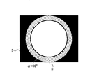
- ⁇ Example of overlapping area> 6 to 9 are diagrams for explaining an example of the overlapping area according to the embodiment of the present invention. 6 to 9, an example will be described in which the illustrated first image 3 and second image 4 are images captured by the respective image sensors, for example. Further, in the drawing, the black-colored range is a range indicating an example of a range in which light does not enter, as in FIG. Moreover, the 1st image 3 and the 2nd image 4 have a pixel used as the overlap area 2 (FIG. 2), respectively. For example, as illustrated, it is assumed that the overlapping area 2 is imaged at an incident angle ⁇ of 90 ° or more. Specifically, in the first image 3, the overlapping area 2 is a first range 31, for example, as illustrated.
- the overlapping area 2 is a second range 41, for example, as illustrated.
- the overlapping area 2 is, for example, a range in which each image is imaged in a range outside the pixel corresponding to the incident angle ⁇ of 90 °.
- the first image 3 has a first pixel indicating the overlapping area 2, and for example, the first pixel is a pixel in the first range 31.
- the second image 4 includes a second pixel indicating the overlap region 2, and the second pixel is a pixel in the second range 41, for example.
- the first pixel and the second pixel are used for calculating the joining position.
- the range used for calculating the position where the images are to be joined or the like may not be the entire range of the first range 31 and the second range 41. Specifically, the following ranges may be used in the calculation of the position where the images are joined together.
- the range used for calculating the position where the images are to be joined may be a part of the first range 31 and the second range 41.
- the first use range 32 is a part of the first range 31, and is an example in which a part of the first range 31 is used in a process such as calculation of a position where the images are joined. is there.
- the second use range 42 is a part of the second range 41, and an example in which a part of the second range 41 is used in processing such as calculation of a position where the images are to be joined is performed. It is.
- Each image has a high image height h, that is, in the image, distortion, aberration, and the like often deteriorate as the pixel is located in the outer range.
- the first use range 32 and the second use range 42 are limited to a range in which the image height h is low in the first range 31 and the second range 41. That is, the information processing apparatus or the like can calculate the position where the images are joined together with high accuracy when the first use range 32 and the second use range 42 are the ranges where the distortion and aberration are small.
- the image processing system includes an information processing apparatus having the following software configuration and an imaging apparatus.
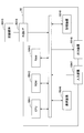
- FIG. 10 is a block diagram illustrating an example of the software configuration of the information processing apparatus in the image processing system according to the embodiment of the present invention.
- the PC 50 which is an example of an information processing apparatus having a software configuration as illustrated will be described as an example.
- the PC 50 has a kernel unit KN configured by, for example, an OS (Operating System).
- the PC 50 includes an application unit AP configured by installing image processing application software in advance.
- the PC 50 has an image output unit VE configured by installing so-called viewer application software in advance.
- the kernel unit KN is configured by, for example, a USB (Universal Serial Bus) driver or the like. That is, in the image processing system 10, the kernel unit KN connects the omnidirectional camera 1 and the PC 50 through an interface such as USB, and inputs and outputs data and the like between the PC 50 and the omnidirectional camera 1. Then, the kernel unit KN sends data input from the omnidirectional camera 1 to the application unit AP.
- a USB Universal Serial Bus
- the application unit AP performs image processing on the captured image input from the omnidirectional camera 1 by the kernel unit KN, and generates an output image to be displayed to the user UR by the image output unit VE. Details of the image processing for the captured image will be described later.
- the image output unit VE displays an output image generated by the application unit AP to the user UR. Further, the image output unit VE may input an operation from the user UR through a GUI (Graphical User Interface) or the like. For example, the image output unit VE causes the user to set a setting value related to stitching. Then, the input set value or the like is sent to the application unit AP. With such a configuration, a setting value used by the application unit AP for image processing may be input. Details of the setting values will be described later. Further, the GUI for inputting setting values and the like is not limited to being displayed by the image output unit VE, and may be displayed by other software.
- FIG. 11 is a block diagram illustrating an example of a hardware configuration of an information processing apparatus according to an embodiment of the present invention.
- the PC 50 is a computer having the following hardware configuration.
- the PC 50 includes a CPU (Central Processing Unit) 50H1, a ROM (Read-Only Memory) 50H2, and a RAM (Random Access Memory) 50H3. Further, the PC 50 includes an external I / F (interface) 50H4, a communication device 50H6, an input device 50H7, an output device 50H8, and a storage device 50H9.
- a CPU Central Processing Unit
- ROM Read-Only Memory
- RAM Random Access Memory
- the CPU 50H1 is a calculation device for performing processing and data processing, and a control device for controlling hardware.
- ROM 50H2 is a storage device that stores programs such as firmware.
- the RAM 50H3 is a storage device that serves as a work area for operations and the like.
- the external I / F 50H4 is an interface for inputting / outputting a file or the like to / from a connected recording medium 50H5 such as a USB memory.
- a connected recording medium 50H5 such as a USB memory.
- the external I / F 50H4 is a connector, a cable, a driver, or the like.
- the communication device 50H6 is a device that communicates with an external device such as the printer PR1 via a network or the like.
- the communication device 50H6 is a connector, a cable, a driver, or the like.
- the input device 50H7 is an interface for inputting data from a user operation and a connected external device.
- the input device 50H7 is a keyboard, a mouse, or a combination thereof.
- the input device 50H7 is a connector, a driver, or the like for connecting an external device such as a keyboard or an imaging device.
- the output device 50H8 is an interface for displaying data to the user and outputting data to the connected external device.
- the output device 50H8 is a display or the like.
- the output device 50H8 is a connector, a driver, or the like for connecting a display or the like.
- Storage device 50H9 stores input data and programs.
- the storage device 50H9 is a main storage device, an auxiliary storage device, or the like.
- the hardware configuration is not limited to the illustrated configuration.
- the hardware configuration may further include an arithmetic device, a control device, a storage device, or the like inside or outside.
- the information processing apparatus may be configured by a plurality of apparatuses instead of a single apparatus.
- FIG. 12 is a flowchart showing an example of overall processing by the information processing apparatus in the image processing system according to the embodiment of the present invention.
- the PC performs the following processing on the captured image input from the omnidirectional camera.
- step S101 the PC acquires conversion data.
- the conversion data is acquired for each image sensor. That is, when the omnidirectional camera 1 shown in FIG. 1 is connected to a PC, the PC acquires respective conversion data corresponding to the two respective image sensors.
- first conversion data the conversion data corresponding to the first image sensor 1H3
- second conversion data the conversion data corresponding to the second image sensor 1H4
- the PC acquires the first conversion data and the second conversion data from the omnidirectional camera 1, respectively.
- the PC since the first conversion data and the second conversion data are different for each omnidirectional camera, when a different omnidirectional camera is connected, the PC newly connects the first conversion data and the second conversion data. Obtained from a spherical camera.
- an image generated by conversion based on the first conversion data that is, an image generated by converting the first captured image
- an image generated by conversion based on the second conversion data that is, an image generated by converting the second captured image
- the conversion data may be associated with an imaging device such as a spherical camera. That is, the PC acquires and stores the respective first conversion data and second conversion data for each imaging apparatus.
- the conversion data may include identification data indicating an ID (Identification) or an identification number of the omnidirectional camera that can identify each omnidirectional camera.
- the PC acquires the identification number of the connected omnidirectional camera, and previously acquired the identification number of the connected omnidirectional camera. The identification number etc. which conversion data has are collated.
- the PC may use the conversion data specified based on the identification data. Good. That is, the PC can use the conversion data corresponding to each imaging device based on the identification data.
- the conversion data is data in the LUT (Look Up Table) format as shown below (Table 1).
- the conversion data is data that associates coordinates before conversion with coordinate values after conversion. Also, the conversion data differs for each omnidirectional camera. The omnidirectional camera has different parameters for each device. For this reason, the conversion data affected by the parameter is also different for each omnidirectional camera. Specifically, the conversion data is a so-called mesh file or the like. That is, the conversion data is data used when texture mapping is performed in OpenGL (registered trademark), for example. Further, when converted based on the conversion data, the captured image is arranged in a part of the output image, and processing such as distortion correction is performed. Details of the process using the conversion data will be described in step S103 described later.
- step S102 the PC inputs a plurality of captured images. That is, in step S102, a plurality of captured images are input from the connected omnidirectional camera. Specifically, in the example illustrated in FIG. 1, the PC inputs two captured images. That is, in the example illustrated in FIG. 1, the PC inputs the first captured image and the second captured image, respectively.
- step S103 the PC joins the converted images to generate an output image.
- the PC converts the captured image based on the conversion data to generate a converted image. Specifically, the PC performs the following conversion.
- step S103 a plurality of captured images of the format shown in FIG. 14 are input.
- each pixel included in the captured image and the output image has an angle with respect to a predetermined axis (hereinafter referred to as “vertical angle ⁇ ”) and an angle orthogonal to the vertical angle ⁇ (hereinafter referred to as “horizontal angle ⁇ ”).
- the horizontal angle ⁇ is assumed to be 0 ° to 360 °.
- the horizontal angle ⁇ may be ⁇ 180 ° to 180 °.
- the vertical angle ⁇ is assumed to be 0 ° to 180 °.
- the vertical angle ⁇ may be ⁇ 90 ° to 90 °.
- FIG. 15 is a diagram illustrating an example of conversion based on conversion data according to an embodiment of the present invention.
- FIG. 15A is a diagram illustrating an example of the output image IMGOUT.
- FIG. 15B is a diagram illustrating an example of a captured image.
- the PC converts the captured image based on the conversion data shown in Table 1 above.
- each pixel included in the captured image is mapped to coordinates on the output image IMGOUT by the PC based on the conversion data shown in Table 1 above.
- the conversion data shown in (Table 1) is data for projecting the pixels of the captured image shown in the plane coordinate system (x, y) onto the spherical coordinate system ( ⁇ , ⁇ ).
- the projection data as described in FIGS. 4 and 5 is reflected in the conversion data according to the specifications of the lens. That is, when the conversion is performed based on the conversion data, distortion aberration and the like are corrected. In the conversion, the following rotation conversion may be performed.
- FIG. 16 is a diagram illustrating an example of rotation conversion according to an embodiment of the present invention.
- FIGS. 16A and 16B For example, an example in which the output image IMGOUT is output based on a captured image as illustrated in FIGS. 16A and 16B will be described.
- the PC may perform rotation conversion that corrects “top-and-bottom reversal” by conversion.
- the PC may further perform rotation conversion that inverts the captured image shown in FIG. 16B to generate an output image IMGOUT as shown in FIG. .
- the images converted based on the conversion data are connected to generate and output an output image.
- the joining is a process as follows.
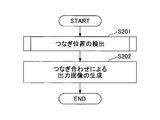
- FIG. 17 is a flowchart for explaining an example of joining by the information processing apparatus according to the embodiment of the present invention.
- the illustrated process is, for example, a process performed in S103 illustrated in FIG.
- step S201 the PC detects the connection position.
- a pixel indicating a subject imaged in the overlapping area 2 shown in FIG. 2 is detected in each of the converted captured images.
- the connection position detection is realized by the following process, for example.
- FIG. 18 is a flowchart for explaining an example of connection position detection by the information processing apparatus according to the embodiment of the present invention.
- step S201 shown in FIG. 17 the process shown in FIG. 18 is performed to detect a connection position where the first converted image and the second converted image are connected.
- step S301 and step S302 are repeatedly performed for each pixel ( ⁇ , ⁇ ) included in the overlapping area 2 (FIG. 2) related to the first converted image.
- the horizontal angle ⁇ (FIG. 13) in the spherical coordinate system ( ⁇ , ⁇ ) of the pixel ( ⁇ , ⁇ ) included in the overlapping area 2 is “0 °” to “360 °”.
- the vertical angle ⁇ (FIG.
- step S301 the PC sets an image to be searched (hereinafter referred to as “pattern image”) in pattern matching.
- pattern image an image to be searched
- the following pattern image is set.
- FIG. 19 and 20 are diagrams for explaining an example of pattern matching in connection position detection according to an embodiment of the present invention.
- a pattern image 300 as illustrated in FIG. 19 is set.
- an image having “11 ⁇ 11 pixels” with a pixel indicated by “ ⁇ ” in the figure as a central pixel is cut out from the overlapping area 2 (FIG. 2) of the first converted image, and the pattern image 300 is set.
- the horizontal angle ⁇ is connected at both ends (that is, “0 °” and “360 °”), one end and the other end are connected.
- a pixel is handled.
- the PC detects the connection position.
- the connection position is detected as follows based on the pattern image set in step S301.
- FIG. 20 shows an example of a connection position detection method by pattern matching in the overlap area 2 of the second converted image.
- the connection position is indicated by “deviation amount ( ⁇ , ⁇ )” as illustrated.
- the PC moves the pattern image 300 illustrated in FIG. 19 in the horizontal angle ⁇ and vertical angle ⁇ (in the drawing, the horizontal and vertical directions). Move.
- the PC calculates the similarity used in template matching or the like, and calculates the distance between the position where the similarity is high and the position where the pattern image 300 is currently arranged.
- the similarity is calculated by, for example, the SAD (Sum of Absolute Difference) method or the SSD (Sum of Squared Difference) method.
- the similarity may be calculated by, for example, a POC (Phase-Only Correlation) method, a ZNCC (Zero-means Normalized Cross-Correlation) method, or the like.
- the distance calculated in this way is the shift amount ( ⁇ , ⁇ ). That is, in FIG. 20, when the pattern image 300 at the “as-is position” moves by the shift amount ( ⁇ , ⁇ ), the pattern image 300 matches the image indicated by the overlapping area 2 included in the second converted image. In this way, in this example, the PC detects the position indicated by the calculated shift amount ( ⁇ , ⁇ ) as the connection position.
- step S202 the PC generates an output image by stitching.
- the output image is generated by connecting and synthesizing the first converted image and the second converted image as follows.
- FIG. 21 is a diagram illustrating an example of generation of an output image according to an embodiment of the present invention.
- a case where the first captured image IMG1 and the second captured image IMG2 as shown in the drawing are respectively converted and connected to generate the output image IMGOUT will be described as an example.
- the first captured image IMG1 and the second captured image IMG2 are converted based on the respective conversion data
- the first captured image IMG1 and the second captured image IMG2 become the first converted image IMGC1 and the second converted image IMGC2, and one of the output images IMGOUT. It arrange
- the regions where the pixels exist only in the first captured image IMG1 or the second captured image IMG2 are the respective pixels included in the first captured image IMG1 or the second captured image IMG2. Is adopted.
- a region where pixels are present in both the first captured image IMG1 and the second captured image IMG2, that is, the overlapping region 2 is the first captured image IMG1 or the second captured image IMG2.
- the pixels included in are blended and adopted. Each pixel may be corrected when employed as a pixel of the output image IMGOUT.
- the PC converts each image in the overlap area 2 so that the pixels of the first converted image IMGC1 and the second converted image IMGC2 are connected at the connection position. Deploy.
- the connecting position may be adjusted by a user operation.
- the connection position differs depending on the distance to the subject in each captured image. Specifically, it is assumed that the distance to the subject shown in each captured image is infinite in one captured image and close in the other captured image. In such a case, the connection position is often different from the case where the distance at which both are imaged is infinite. Therefore, it is desirable that the connecting position can be adjusted.
- the user views the output image IMGOUT to be output, and inputs a movement amount for moving one of the connected converted images.
- a movement amount for moving one of the connected converted images For example, first, the user views the output image IMGOUT to be output, and inputs a movement amount for moving one of the connected converted images.
- the position where the second converted image IMGC2 is arranged is moved and adjusted will be described.
- the position where the first converted image IMGC1 is arranged may be moved.
- the movement amount includes a movement amount in the ⁇ direction that moves the position where the second converted image IMGC2 is arranged (hereinafter referred to as “first movement amount P1”), and the second converted image IMGC2.
- first movement amount P1 a movement amount in the ⁇ direction that moves the position where the second converted image IMGC2 is arranged
- second movement amount P2 Is a value that indicates the amount of movement in the ⁇ direction (hereinafter referred to as “second movement amount P2”) that moves the position where is placed.
- the PC inputs at least one of the first movement amount P1 and the second movement amount P2.
- the image output unit VE FIG. 10
- the PC displays a GUI such as a scroll bar and inputs a user operation from the displayed GUI
- the PC can input the movement amount.
- the PC places the second converted image IMGC2 at the position indicated by the input movement amount. In this way, the PC can join the images with high accuracy even when there is parallax or the like.
- the second movement amount P2 is input and the connecting position is adjusted.
- the deviation is likely to occur in the ⁇ direction based on parallax or the like. That is, it is more desirable that the amount of overlapping of each converted image is adjusted by the PC. Therefore, when the second movement amount P2 is input to the PC and adjustment is performed in the ⁇ direction, the PC can connect the images with higher accuracy even if there is parallax or the like.
- FIG. 22 is a functional block diagram illustrating an example of a functional configuration of the image processing system according to the embodiment of the present invention.
- the image processing system 10 includes an omnidirectional camera 1 that is an example of an imaging device, and a PC 50 that is an example of an information processing device.
- the PC 50 includes an input unit 10F1, an acquisition unit 10F2, and a generation unit 10F3.
- the input unit 10F1 inputs at least a first captured image and a second captured image, which are captured images, from the omnidirectional camera 1 respectively.
- the input unit 10F1 is realized by, for example, the communication device 50H6 (FIG. 11) or the input device 50H7 (FIG. 11).
- the acquisition unit 10F2 acquires first conversion data used to convert the first captured image and second conversion data used to convert the second captured image, respectively.
- the acquisition unit 10F2 is realized by, for example, the communication device 50H6 (FIG. 11) or the input device 50H7 (FIG. 11).
- the generation unit 10F3 generates an output image by connecting the converted images generated by conversion based on the first conversion data and the second conversion data.
- the generation unit 10F3 is realized by, for example, the CPU 50H1 (FIG. 11).
- the PC 50 acquires the first conversion data and the second conversion data from the omnidirectional camera 1 in advance by the acquisition unit 10F2. Therefore, the PC 50 can convert the first captured image and the second captured image input by the input unit 10F1 on the PC 50 side. Therefore, the PC 50 can generate the output image by connecting the converted images by the generation unit 10F3.
- the conversion data is data reflecting the parameters of each imaging apparatus. Therefore, the conversion data differs for each imaging device. Therefore, as in the configuration shown in the figure, the PC 50 performs conversion in accordance with the parameters of each imaging device. Therefore, when the conversion data is acquired for each imaging device, the PC 50 converts each captured image to obtain higher accuracy. It is possible to connect a plurality of converted images well and generate an output image. Then, the image processing system 10 can output an output image to the user UR.
- the embodiment according to the present invention may be realized by a program including firmware. That is, the embodiment according to the present invention may be realized by a program for causing an image processing system having an information processing apparatus or one or more information processing apparatuses to execute an image processing method.
- the program is installed in the information processing apparatus or the like via a recording medium or a network.
- the recording medium is a computer-readable recording medium such as an optical disk.
- the computer-readable recording medium may be a portable recording medium such as a USB (Universal Serial Bus) memory and a semiconductor memory such as a flash memory.
Landscapes
- Engineering & Computer Science (AREA)
- Multimedia (AREA)
- Signal Processing (AREA)
- Theoretical Computer Science (AREA)
- Physics & Mathematics (AREA)
- General Physics & Mathematics (AREA)
- Computing Systems (AREA)
- Image Processing (AREA)
- Studio Devices (AREA)
Priority Applications (5)
| Application Number | Priority Date | Filing Date | Title |
|---|---|---|---|
| JP2018506784A JP6687103B2 (ja) | 2016-03-22 | 2016-12-27 | 画像処理システム、画像処理方法及びプログラム |
| EP16895550.8A EP3435652A1 (de) | 2016-03-22 | 2016-12-27 | Bildverarbeitungssystem, bildverarbeitungsverfahren und programm |
| KR1020187027055A KR20180113601A (ko) | 2016-03-22 | 2016-12-27 | 화상 처리 시스템, 화상 처리 방법 및 프로그램 |
| CN201680083721.0A CN108886562B (zh) | 2016-03-22 | 2016-12-27 | 图像处理系统、图像处理方法及计算机可读存储介质 |
| US16/135,397 US10750087B2 (en) | 2016-03-22 | 2018-09-19 | Image processing system, image processing method, and computer-readable medium |
Applications Claiming Priority (2)
| Application Number | Priority Date | Filing Date | Title |
|---|---|---|---|
| JP2016-057354 | 2016-03-22 | ||
| JP2016057354 | 2016-03-22 |
Related Child Applications (1)
| Application Number | Title | Priority Date | Filing Date |
|---|---|---|---|
| US16/135,397 Continuation US10750087B2 (en) | 2016-03-22 | 2018-09-19 | Image processing system, image processing method, and computer-readable medium |
Publications (1)
| Publication Number | Publication Date |
|---|---|
| WO2017163527A1 true WO2017163527A1 (ja) | 2017-09-28 |
Family
ID=59901044
Family Applications (1)
| Application Number | Title | Priority Date | Filing Date |
|---|---|---|---|
| PCT/JP2016/088958 Ceased WO2017163527A1 (ja) | 2016-03-22 | 2016-12-27 | 画像処理システム、画像処理方法及びプログラム |
Country Status (6)
| Country | Link |
|---|---|
| US (1) | US10750087B2 (de) |
| EP (1) | EP3435652A1 (de) |
| JP (1) | JP6687103B2 (de) |
| KR (1) | KR20180113601A (de) |
| CN (1) | CN108886562B (de) |
| WO (1) | WO2017163527A1 (de) |
Families Citing this family (5)
| Publication number | Priority date | Publication date | Assignee | Title |
|---|---|---|---|---|
| KR20180051288A (ko) * | 2016-11-08 | 2018-05-16 | 삼성전자주식회사 | 디스플레이 장치 및 그 제어 방법 |
| US10966017B2 (en) | 2019-01-04 | 2021-03-30 | Gopro, Inc. | Microphone pattern based on selected image of dual lens image capture device |
| JP7720723B2 (ja) * | 2021-05-31 | 2025-08-08 | キヤノン株式会社 | 画像処理装置、画像処理方法、及びプログラム |
| JP2024030637A (ja) * | 2022-08-24 | 2024-03-07 | キヤノン株式会社 | 電子機器および電子機器の制御方法 |
| US12501219B2 (en) | 2023-06-01 | 2025-12-16 | Gopro, Inc. | Dual-lens image capture device microphone positioning |
Citations (6)
| Publication number | Priority date | Publication date | Assignee | Title |
|---|---|---|---|---|
| JP2008048022A (ja) * | 2006-08-11 | 2008-02-28 | Canon Inc | 監視システム及び方法、並びにプログラム及び記憶媒体 |
| JP2011234172A (ja) * | 2010-04-28 | 2011-11-17 | Fujitsu Ltd | 画像処理装置、画像処理方法及び画像処理用コンピュータプログラムならびに撮像装置 |
| JP2012050515A (ja) * | 2010-08-31 | 2012-03-15 | Canon Inc | 画像処理装置および方法 |
| JP2013219617A (ja) * | 2012-04-10 | 2013-10-24 | Canon Inc | 情報処理装置、制御方法、プログラム、及び撮像システム |
| JP2015046051A (ja) * | 2013-08-28 | 2015-03-12 | 株式会社リコー | 画像処理装置、画像処理方法、プログラムおよび撮像システム |
| JP5842886B2 (ja) | 2012-09-11 | 2016-01-13 | 株式会社リコー | 画像処理装置、画像処理方法、プログラムおよび撮像システム |
Family Cites Families (22)
| Publication number | Priority date | Publication date | Assignee | Title |
|---|---|---|---|---|
| JPS5842886B2 (ja) | 1976-12-14 | 1983-09-22 | 松下電器産業株式会社 | 定電圧装置 |
| US6717608B1 (en) * | 1999-12-31 | 2004-04-06 | Stmicroelectronics, Inc. | Motion estimation for panoramic digital camera |
| US7006706B2 (en) * | 2002-04-12 | 2006-02-28 | Hewlett-Packard Development Company, L.P. | Imaging apparatuses, mosaic image compositing methods, video stitching methods and edgemap generation methods |
| WO2006022630A1 (en) * | 2004-07-26 | 2006-03-02 | Silicon Optix, Inc. | Panoramic vision system and method |
| US8391640B1 (en) * | 2008-08-29 | 2013-03-05 | Adobe Systems Incorporated | Method and apparatus for aligning and unwarping distorted images |
| CN102222337A (zh) * | 2011-06-14 | 2011-10-19 | 重庆大学 | 用于图像拼接的鱼眼图像校正方法 |
| JP6123274B2 (ja) | 2012-03-08 | 2017-05-10 | 株式会社リコー | 撮像装置 |
| JP2013214947A (ja) | 2012-03-09 | 2013-10-17 | Ricoh Co Ltd | 撮像装置、撮像システム、画像処理方法、情報処理装置、及びプログラム |
| TW201403553A (zh) * | 2012-07-03 | 2014-01-16 | Automotive Res & Testing Ct | 自動校正鳥瞰影像方法 |
| JP6079031B2 (ja) | 2012-08-01 | 2017-02-15 | 株式会社リコー | 撮像装置 |
| JP6065474B2 (ja) | 2012-09-11 | 2017-01-25 | 株式会社リコー | 撮像制御装置、撮像制御方法およびプログラム |
| JP5971207B2 (ja) | 2012-09-18 | 2016-08-17 | 株式会社リコー | 画像調整装置、画像調整方法およびプログラム |
| JP2014112302A (ja) | 2012-12-05 | 2014-06-19 | Ricoh Co Ltd | 所定領域管理システム、通信方法、及びプログラム |
| JP6044328B2 (ja) | 2012-12-26 | 2016-12-14 | 株式会社リコー | 画像処理システム、画像処理方法およびプログラム |
| CN105659287B (zh) | 2013-08-28 | 2018-08-17 | 株式会社理光 | 图像处理装置、图像处理方法和成像系统 |
| US9892493B2 (en) * | 2014-04-21 | 2018-02-13 | Texas Instruments Incorporated | Method, apparatus and system for performing geometric calibration for surround view camera solution |
| US9900505B2 (en) * | 2014-07-23 | 2018-02-20 | Disney Enterprises, Inc. | Panoramic video from unstructured camera arrays with globally consistent parallax removal |
| TWI558208B (zh) * | 2015-07-14 | 2016-11-11 | 旺玖科技股份有限公司 | 影像處理方法、影像處理裝置及顯示系統 |
| KR20170025058A (ko) * | 2015-08-27 | 2017-03-08 | 삼성전자주식회사 | 영상 처리 장치 및 이를 포함하는 전자 시스템 |
| US20170126985A1 (en) * | 2015-10-30 | 2017-05-04 | Gopro, Inc. | Enumeration of Cameras in an Array |
| US10116880B2 (en) * | 2016-02-05 | 2018-10-30 | Sintai Optical (Shenzhen) Co., Ltd. | Image stitching method and image processing apparatus |
| US10194089B2 (en) * | 2016-02-08 | 2019-01-29 | Qualcomm Incorporated | Systems and methods for implementing seamless zoom function using multiple cameras |
-
2016
- 2016-12-27 EP EP16895550.8A patent/EP3435652A1/de not_active Withdrawn
- 2016-12-27 JP JP2018506784A patent/JP6687103B2/ja active Active
- 2016-12-27 KR KR1020187027055A patent/KR20180113601A/ko not_active Abandoned
- 2016-12-27 CN CN201680083721.0A patent/CN108886562B/zh active Active
- 2016-12-27 WO PCT/JP2016/088958 patent/WO2017163527A1/ja not_active Ceased
-
2018
- 2018-09-19 US US16/135,397 patent/US10750087B2/en active Active
Patent Citations (6)
| Publication number | Priority date | Publication date | Assignee | Title |
|---|---|---|---|---|
| JP2008048022A (ja) * | 2006-08-11 | 2008-02-28 | Canon Inc | 監視システム及び方法、並びにプログラム及び記憶媒体 |
| JP2011234172A (ja) * | 2010-04-28 | 2011-11-17 | Fujitsu Ltd | 画像処理装置、画像処理方法及び画像処理用コンピュータプログラムならびに撮像装置 |
| JP2012050515A (ja) * | 2010-08-31 | 2012-03-15 | Canon Inc | 画像処理装置および方法 |
| JP2013219617A (ja) * | 2012-04-10 | 2013-10-24 | Canon Inc | 情報処理装置、制御方法、プログラム、及び撮像システム |
| JP5842886B2 (ja) | 2012-09-11 | 2016-01-13 | 株式会社リコー | 画像処理装置、画像処理方法、プログラムおよび撮像システム |
| JP2015046051A (ja) * | 2013-08-28 | 2015-03-12 | 株式会社リコー | 画像処理装置、画像処理方法、プログラムおよび撮像システム |
Non-Patent Citations (1)
| Title |
|---|
| See also references of EP3435652A4 |
Also Published As
| Publication number | Publication date |
|---|---|
| JP6687103B2 (ja) | 2020-04-22 |
| KR20180113601A (ko) | 2018-10-16 |
| JPWO2017163527A1 (ja) | 2018-12-27 |
| EP3435652A4 (de) | 2019-01-30 |
| US20190020818A1 (en) | 2019-01-17 |
| CN108886562B (zh) | 2021-07-13 |
| CN108886562A (zh) | 2018-11-23 |
| EP3435652A1 (de) | 2019-01-30 |
| US10750087B2 (en) | 2020-08-18 |
Similar Documents
| Publication | Publication Date | Title |
|---|---|---|
| US20200288059A1 (en) | Image processor, image processing method and program, and imaging system | |
| JP6467787B2 (ja) | 画像処理システム、撮像装置、画像処理方法およびプログラム | |
| JP5846549B1 (ja) | 画像処理システム、画像処理方法、プログラム、撮像システム、画像生成装置、画像生成方法およびプログラム | |
| CN108600576B (zh) | 图像处理装置、方法和系统以及计算机可读记录介质 | |
| JP6687103B2 (ja) | 画像処理システム、画像処理方法及びプログラム | |
| US20110249117A1 (en) | Imaging device, distance measuring method, and non-transitory computer-readable recording medium storing a program | |
| US20110187829A1 (en) | Image capture apparatus, image capture method and computer readable medium | |
| JP2017208619A (ja) | 画像処理装置、画像処理方法、プログラム及び撮像システム | |
| JP6812862B2 (ja) | 画像処理システム、撮像装置、画像処理方法及びプログラム | |
| JP6600936B2 (ja) | 画像処理装置、画像処理方法、画像処理システム、プログラム、及び記録媒体 | |
| TWI617195B (zh) | 影像擷取裝置及其影像拼接方法 | |
| JP2010217984A (ja) | 像検出装置及び像検出方法 | |
| US11928775B2 (en) | Apparatus, system, method, and non-transitory medium which map two images onto a three-dimensional object to generate a virtual image | |
| JP2017092756A (ja) | 画像処理装置、画像処理方法、画像投影システムおよびプログラム | |
| CN107580157B (zh) | 图像处理装置、图像处理方法 | |
| JP2014086925A (ja) | 情報処理装置、情報処理システム、およびプログラム | |
| JP6291748B2 (ja) | 撮像装置、撮像方法、及びプログラム | |
| JP2016142991A (ja) | 画像処理システム、情報処理装置、画像処理方法、及びプログラム | |
| JP2016040883A (ja) | 画像処理装置、画像処理方法、画像処理システム、及びプログラム | |
| JP6427888B2 (ja) | 画像表示システム、画像表示装置及び画像表示方法 | |
| JP6614500B2 (ja) | 画像読取装置、携帯端末、画像読取方法及び画像読取プログラム | |
| WO2017057426A1 (ja) | 投影装置、コンテンツ決定装置、投影方法、および、プログラム | |
| WO2020152810A1 (ja) | カメラ情報算出装置、システム、カメラ情報算出方法およびプログラム | |
| JP2019088015A (ja) | 画像処理システム、撮像装置、画像処理方法およびプログラム | |
| JP7135277B2 (ja) | 画像処理装置、画像処理方法及びプログラム |
Legal Events
| Date | Code | Title | Description |
|---|---|---|---|
| WWE | Wipo information: entry into national phase |
Ref document number: 2018506784 Country of ref document: JP |
|
| ENP | Entry into the national phase |
Ref document number: 20187027055 Country of ref document: KR Kind code of ref document: A |
|
| WWE | Wipo information: entry into national phase |
Ref document number: 1020187027055 Country of ref document: KR |
|
| NENP | Non-entry into the national phase |
Ref country code: DE |
|
| WWE | Wipo information: entry into national phase |
Ref document number: 2016895550 Country of ref document: EP |
|
| ENP | Entry into the national phase |
Ref document number: 2016895550 Country of ref document: EP Effective date: 20181022 |
|
| 121 | Ep: the epo has been informed by wipo that ep was designated in this application |
Ref document number: 16895550 Country of ref document: EP Kind code of ref document: A1 |