WO2017163544A1 - Dispositif de commande de communication de dispositif à dispositif, station de base, terminal radio et procédé associé à ceux-ci - Google Patents
Dispositif de commande de communication de dispositif à dispositif, station de base, terminal radio et procédé associé à ceux-ci Download PDFInfo
- Publication number
- WO2017163544A1 WO2017163544A1 PCT/JP2017/000755 JP2017000755W WO2017163544A1 WO 2017163544 A1 WO2017163544 A1 WO 2017163544A1 JP 2017000755 W JP2017000755 W JP 2017000755W WO 2017163544 A1 WO2017163544 A1 WO 2017163544A1
- Authority
- WO
- WIPO (PCT)
- Prior art keywords
- transmission
- base station
- relay terminal
- terminal
- relay
- Prior art date
- Legal status (The legal status is an assumption and is not a legal conclusion. Google has not performed a legal analysis and makes no representation as to the accuracy of the status listed.)
- Ceased
Links
Images


Classifications
-
- H—ELECTRICITY
- H04—ELECTRIC COMMUNICATION TECHNIQUE
- H04W—WIRELESS COMMUNICATION NETWORKS
- H04W72/00—Local resource management
- H04W72/50—Allocation or scheduling criteria for wireless resources
- H04W72/52—Allocation or scheduling criteria for wireless resources based on load
-
- H—ELECTRICITY
- H04—ELECTRIC COMMUNICATION TECHNIQUE
- H04W—WIRELESS COMMUNICATION NETWORKS
- H04W28/00—Network traffic management; Network resource management
- H04W28/02—Traffic management, e.g. flow control or congestion control
- H04W28/10—Flow control between communication endpoints
- H04W28/12—Flow control between communication endpoints using signalling between network elements
-
- H—ELECTRICITY
- H04—ELECTRIC COMMUNICATION TECHNIQUE
- H04W—WIRELESS COMMUNICATION NETWORKS
- H04W28/00—Network traffic management; Network resource management
- H04W28/02—Traffic management, e.g. flow control or congestion control
- H04W28/10—Flow control between communication endpoints
- H04W28/14—Flow control between communication endpoints using intermediate storage
-
- H—ELECTRICITY
- H04—ELECTRIC COMMUNICATION TECHNIQUE
- H04W—WIRELESS COMMUNICATION NETWORKS
- H04W72/00—Local resource management
- H04W72/20—Control channels or signalling for resource management
- H04W72/21—Control channels or signalling for resource management in the uplink direction of a wireless link, i.e. towards the network
-
- H—ELECTRICITY
- H04—ELECTRIC COMMUNICATION TECHNIQUE
- H04W—WIRELESS COMMUNICATION NETWORKS
- H04W88/00—Devices specially adapted for wireless communication networks, e.g. terminals, base stations or access point devices
- H04W88/02—Terminal devices
- H04W88/04—Terminal devices adapted for relaying to or from another terminal or user
-
- H—ELECTRICITY
- H04—ELECTRIC COMMUNICATION TECHNIQUE
- H04W—WIRELESS COMMUNICATION NETWORKS
- H04W92/00—Interfaces specially adapted for wireless communication networks
- H04W92/16—Interfaces between hierarchically similar devices
- H04W92/18—Interfaces between hierarchically similar devices between terminal devices
Definitions
- This disclosure relates to direct communication between devices (device-to-device (D2D) communication), and more particularly to control of side link transmission from a remote terminal to a relay terminal.
- D2D device-to-device
- D2D communication A form in which a wireless terminal communicates directly with another wireless terminal without going through an infrastructure network such as a base station is called device-to-device (D2D) communication.
- the D2D communication includes at least one of direct communication (Direct Communication) and direct discovery (Direct Discovery).
- a plurality of wireless terminals that support D2D communication form a D2D communication group autonomously or according to a network instruction, and communicate with other wireless terminals in the D2D communication group.
- Proximity-based services defined in 3GPP Release 12 is an example of D2D communication (see, for example, Non-Patent Document 1).
- ProSe direct discovery is a wireless terminal that can execute ProSe (ProSe-enabled User Equipment (UE)) and other ProSe-enabled UEs, and these two UEs have wireless communication technology (for example, Evolved Universal Universal Terrestrial Radio Access -UTRA) It is performed by the discovery procedure using only the technology (technology).
- ProSe direct discovery may be performed by three or more ProSe-enabled UEs.
- ProSe direct communication enables the establishment of a communication path between two or more ProSe-enabled UEs existing in the direct communication range after the ProSe direct discovery procedure.
- ProSe direct communication allows ProSe-enabled UEs to communicate with other ProSe-enabled UEs without going through a public land mobile communication network (Public Land Mobile Mobile Network (PLMN)) that includes a base station (eNodeB (eNB)). Allows to communicate directly with.
- PLMN Public Land Mobile Mobile Network
- eNB base station
- ProSe direct communication may be performed using the same wireless communication technology (E-UTRA technology) as that used to access the base station (eNB), or wireless technology of Wireless Local Area Network (WLAN) (ie IEEE 802.11 (radio technology) may be used.
- E-UTRA technology wireless technology
- WLAN Wireless Local Area Network
- a wireless link between wireless terminals used for direct communication or direct discovery is referred to as a side link (see, for example, Section 14 of Non-Patent Document 2).
- Sidelink transmission uses the same frame structure as the Long Term Evolution (LTE) frame structure defined for uplink and downlink, and uses a subset of uplink resources in frequency and time domain.
- the radio terminal (UE) performs side link transmission using single carrier frequency division multiplexing (Single-Carrier-FDMA (Frequency-Division-Multiple Access), SC-FDMA) similar to the uplink.
- Single-Carrier-FDMA Frequency-Division-Multiple Access
- radio resources for side link transmission are allocated to UEs by a radio access network (e.g., Evolved Universal Terrestrial Radio Access Network (E-UTRAN)).
- E-UTRAN Evolved Universal Terrestrial Radio Access Network
- the UE that has been permitted side link communication by ProSe function performs ProSe direct discovery or ProSe direct communication using radio resources allocated by the radio access network node (e.g., eNB (eNB)).
- eNB eNB
- sidelink transmission mode 1 For ProSe direct communication, two resource allocation modes, namely scheduled resource resource allocation and scheduled resource resource allocation and automatic resource resource selection are called “sidelink transmission mode 1" and “sidelink transmission mode 2", respectively. (See Section 14 of Non-Patent Document 2).
- a UE desires side link transmission
- the UE requests radio resource allocation for side link transmission from the eNB
- the eNB assigns resources for side link control and data.
- Assign to the UE Specifically, the UE sends a scheduling request to the eNB to request an uplink (UL) data transmission resource (Uplink Shared Channel (UL-SCH) resource) and assigns it with an UL grant.
- UL-SCH Uplink Shared Channel
- UL-SCH Uplink Shared Channel
- Send Sidelink Buffer Status Report (Sidelink BSR) to the eNB in the received UL data transmission resource.
- the eNB determines a side link transmission resource to be allocated to the UE based on the Sidelink BSR, and transmits a side link grant (SL grant) to the UE.
- SL grant side link grant
- SL grant is defined as Downlink Control Information (DCI) format 5.
- DCI Downlink Control Information
- SL grant (DCI format ⁇ ⁇ 5) includes contents such as Resource for PSCCH, Resource block assignment and hopping allocation, and time resource pattern index.
- Resource for PSCCH indicates a radio resource for a side link control channel (i.e., Physical Sidelink Control Channel (PSCCH)).
- Resource block assignment and hopping allocation is a set of frequency resources, that is, a set of subcarriers (resource blocks), for transmitting a sidelink data channel (ie, Physical Sidelink Shared Channel (PSSCH)) for data transmission on the sidelink, Used to determine.
- Time resource pattern index is used to determine a time resource for transmitting PSSCH, that is, a set of subframes.
- a resource block means LTE and LTE-Advanced time-frequency resources, and a plurality of OFDM (or SC-FDMA) symbols continuous in the time domain and a plurality of consecutive OFDM symbols in the frequency domain.
- one resource block includes 12 OFDM (or SC-FDMA) symbols continuous in the time domain and 12 subcarriers in the frequency domain. That is, Resource block assignment and hopping allocation and Time resource pattern index specify a resource block for transmitting PSSCH.
- the UE that is, the side link transmission terminal determines the PSCCH resource and the PSSCH resource according to SL grant.
- the UE autonomously selects a resource for side link control (PSCCH) and data (PSSCH) from the resource pool set by the eNB.
- the eNB may assign a resource pool to be used for autonomous resource selection in the System Information Block (SIB) 18 to the UE.
- SIB System Information Block
- the eNB may assign a resource pool to be used for autonomous resource selection to the UE of Radio Resource Control (RRC) _CONNECTED by dedicated RRC signaling. This resource pool may also be available when the UE is RRC_IDLE.
- RRC Radio Resource Control
- the transmitting side UE When performing direct transmission on the side link, the transmitting side UE (D2D transmitting UE) (hereinafter referred to as the transmitting terminal) uses the radio resource area (resource pool) for the sidelink control channel (ie, PSCCH) Then, scheduling assignment information (Scheduling Assignment) is transmitted.
- the scheduling allocation information is also called Sidelink, Control, Information, (SCI), format, 0.
- the scheduling assignment information includes contents such as resource, block, assignment, and hopping, allocation, time, resource, pattern, index, and modulation, and coding, Scheme (MCS).
- SCI format 0 scheduling resource assignment
- DCI resource format 5 resource grant
- the transmitting terminal transmits data on PSSCH using radio resources according to the scheduling allocation information.
- a receiving UE receives scheduling assignment information from the transmitting terminal on the PSCCH, and receives data on the PSSCH according to the scheduling assignment information.
- transmission terminal is an expression that focuses on the transmission operation of the wireless terminal, and does not mean a wireless terminal dedicated to transmission.
- the term “receiving terminal” is an expression that focuses on the receiving operation of the wireless terminal, and does not mean a terminal dedicated to reception. That is, the transmitting terminal can also perform a receiving operation, and the receiving terminal can also perform a transmitting operation.
- 3GPP Release 12 specifies a partial coverage scenario in which one UE is outside the network coverage and the other UE is within the network coverage (for example, Sections 4.4.3 and 4.5 of Non-Patent Document 1). See 4 and 5.4.4).
- UEs that are out of coverage are called remote UEs or sidelink remote controllers
- UEs that are in coverage and relay between remote UEs and networks are called ProSe UE UE-to-Network Relays or sidelink relays UEs.
- ProSe UE-to-Network Relay relays traffic (downlink and uplink) between remote UE and network (E-UTRA network (E-UTRAN) and EPC).
- ProSe UE-to-Network Relay attaches to the network as a UE, establishes a PDN connection to communicate with a ProSe function ⁇ ⁇ entity or other packet Data Network (PDN), and performs ProSe direct communication. Communicate with the ProSe function entity to get started.
- ProSe UE-to-Network Relay further performs a discovery procedure with remote UE, communicates with remote UE on the direct inter-UE interface (eg, side link or PC5 interface), and between remote UE and network To relay traffic (downlink and uplink).
- IPv4 Internet Protocol Version 4
- DHCPv4 Dynamic Host Configuration Configuration Protocol Version 4
- NAT Network Address Translation
- IPv6 IPv6
- ProSe UE-to-UE Relay is a UE that relays traffic between two remote UEs.
- the distributed relay selection architecture (see, for example, Non-Patent Documents 4-6, 8, and 9) in which the remote UE performs relay selection, and the base station (
- a centralized relay selection architecture (for example, see Non-Patent Documents 7 and 8) in which elements in a network such as eNodeB (eNB) perform relay selection has been proposed.
- the UE-to-Network Relay selection criteria consider the D2D link quality between the remote UE and the relay UE, the backhaul link quality between the relay UE and the eNB, and the D2D link quality and It has been proposed to consider both backhaul link quality (see, for example, Non-Patent Documents 4-9).
- a wireless terminal having D2D communication capability and relay capability such as ProSe UE-to-Network Relay (sidelink UE relay) is referred to as “relay terminal” or “relay UE”.
- a wireless terminal that receives a relay service by the relay UE is referred to as a “remote terminal” or a “remote UE”.
- a remote terminal can also be referred to as a relayed terminal.
- 3GPP TS 23.303 V12.7.0 (2015-12), “3rd Generation Partnership Project; Technical Technical Specification Group Services Services and System Aspects Proximity-based services (ProSe); Stage 2 Release (Release 12), December 2015 3GPP TS 36.213 V12.5.0 (2015-03), “3rd Generation Partnership Project; Technical Specification Group Radio Access Network; Evolved Universal Terrestrial Radio Access (E-UTRA); Physical layer procedures (Release 12) '', March 3GPP TR 23.713 V13.0.0 (2015-09), “3rd Generation Partnership Project; Technical Specification Group Services and System Aspects; Study on extended architecture support for proximity-based services (Release 13) '', September 3GPP® R1-152778, “Support of UE-Network relays”, Qualcomm Incorporated, May 2015 3GPP S2-150925, “UE-to-Network Relay conclusions”, Qualcomm Incorporated, April 2015 3GPP R1-153087, “Discussion on UE-to-Network Re
- the non-patent literature mentioned above determines the amount of uplink data reserved in the relay UE for transmission from the relay UE to the eNB, or determines radio resources for side link transmission from the remote UE to the relay UE. It does not describe what is considered when making adjustments. For example, if there is inconsistency in performance (eg, bandwidth, throughput) between side link transmission from remote UE to relay UE and uplink transmission from relay UE to eNB, the uplink in relay UE May cause a send buffer overflow.
- the uplink transmission buffer is used to store data transmitted on the uplink.
- the significant increase in the occupancy level of the uplink transmission buffer may be due to excessive radio resources allocated for side link transmission from the remote UE to the relay UE. Allocating radio resources that result in excess side link throughput beyond the uplink throughput of the relay UE to side link transmissions from the remote UE to the relay UE may result in wasted side link radio resources.
- One of the objectives that embodiments disclosed herein attempt to achieve is that performance between side link transmission from a remote terminal to a relay terminal and uplink transmission from the relay terminal to the base station (eg, low bandwidth) It is to provide an apparatus, a method, and a program that contribute to avoiding inconsistency of throughput. It should be noted that this object is only one of the objects that the embodiments disclosed herein intend to achieve. Other objects or problems and novel features will become apparent from the description of the present specification or the accompanying drawings.
- an apparatus for controlling device-to-device communication includes a memory and at least one processor coupled to the memory.
- the at least one processor is configured to transmit a band, throughput, or radio resource used for device-to-device (D2D) transmission from a remote terminal to a relay terminal, from the relay terminal to the base station.
- D2D device-to-device
- a method for controlling device-to-device communication includes a bandwidth, throughput, or radio resource used for device-to-device (D2D) transmission from a remote terminal to a relay terminal, wherein Adjusting based on the amount of uplink data reserved in the relay terminal for transmission from the relay terminal to the base station.
- D2D device-to-device
- the base station includes a memory and at least one processor coupled to the memory.
- the at least one processor transmits control information generated based on a buffer state of an uplink transmission buffer that stores uplink data reserved in the relay terminal for transmission from the relay terminal to the base station. Configured to send to.
- the method in the base station obtains the buffer status of an uplink transmission buffer that stores (a) uplink data reserved in the relay terminal for transmission from the relay terminal to the base station. And (b) transmitting control information generated based on the buffer status to a remote terminal.
- the relay terminal includes a memory and at least one processor coupled to the memory.
- the at least one processor remotely transmits control information generated based on a buffer state of an uplink transmission buffer that stores uplink data reserved in the relay terminal for transmission from the relay terminal to a base station. It is configured to transmit to the terminal.
- a method in a relay terminal includes: (a) a buffer state of an uplink transmission buffer that stores uplink data held in the relay terminal for transmission from the relay terminal to a base station. And (b) transmitting control information generated based on the buffer status to a remote terminal.
- the remote terminal includes a memory and at least one processor coupled to the memory.
- the at least one processor transmits control information generated based on a buffer state of an uplink transmission buffer that stores uplink data reserved in the relay terminal for transmission from the relay terminal to the base station. It is configured to receive from a terminal or the base station.
- a method at a remote terminal is generated based on a buffer state of an uplink transmission buffer that stores uplink data reserved in the relay terminal for transmission from the relay terminal to the base station. Receiving control information from the remote terminal or the base station.
- an instruction group (software code) for causing the computer to perform the method according to the second, fourth, sixth, or eighth aspect is provided. Including.
- the plurality of embodiments described below can be implemented independently or in appropriate combinations.
- the plurality of embodiments have different novel features. Therefore, these multiple embodiments contribute to solving different purposes or problems and contribute to producing different effects.
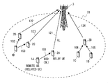
- FIG. 1 shows a configuration example of a wireless communication network according to some embodiments including this embodiment.
- FIG. 1 illustrates an example of UE-to-Network Relay (sidelink relay UE), which includes a plurality of remote UEs 1A, 1B, 1C, and 1D, and a plurality of relays UE2A, 2B, 2C, and 2D is illustrated.
- sidelink relay UE sidelink relay UE
- relay UE1 when a matter common to a plurality of remote UEs including remote UEs 1A, 1B, 1C, and 1D is described, “remote UE1” is simply referred to using reference numeral 1.
- reference numeral 2 is used to simply refer to “relay UE2”.
- the remote UE 1 has at least one radio transceiver and is configured to perform D2D communication with one or more relay UEs 2 on one or more D2D links (e.g., D2D link 101).
- the D2D link is called a PC5 interface or side link.
- the D2D communication includes at least direct communication (i.e., ProSe Direct Communication), and may further include direct discovery (i.e., ProSe Direct Discovery).
- ProSe ⁇ ⁇ Direct Communication is direct communication using side link transmission and is also called Sidelink Direct Communication.
- ProSe Direct Discovery is direct discovery using side link transmission and is also called Sidelink Direct Discovery.
- the remote UE 1 is configured to perform cellular communication within a cellular coverage (cell) 31 provided by the base station (eNB) 3.
- the relay UE2 has at least one radio transceiver, and performs cellular communication in a cellular link (eg, a cellular link 121) including an uplink and a downlink with the base station 3 in the cellular coverage 31, and a D2D link (eg , D2D link 101) and D2D communication (eg, ProSe direct discovery and ProSe direct communication) with remote UE1.
- a cellular link eg, a cellular link 121
- D2D link eg , D2D link 101
- D2D communication eg, ProSe direct discovery and ProSe direct communication
- the base station 3 is an entity arranged in a radio access network (ie, E-UTRAN), provides a cellular coverage 31 including one or more cells, and uses cellular communication technology (eg, E-UTRA technology). It is possible to communicate with the relay UE2 using the cellular link (eg, cellular link 121). Furthermore, the base station 3 is configured to perform cellular communication with the remote UE 1 in the cellular coverage 31.
- E-UTRAN radio access network
- cellular communication technology eg, E-UTRA technology
- Fig. 1 shows three relay configurations.
- one remote UE1A is connected to one relay UE2A.
- the remote UE 1A transmits data on the D2D link 101
- the relay UE 2A transmits the data received from the remote UE 1A to the base station 3 on the cellular link 121 (uplink).
- one remote UE 1B is connected to a plurality of relays UE 2B and 2C.
- the remote UE 1B transmits data on the two D2D links 102 and 103
- the relay UEs 2B and 2C transmit the data received from the remote UE 1B to the base station 3 on the cellular links 122 and 123 (uplink).
- two remote UEs 1C and 1D are connected to one relay UE2D.
- Each of the remote UEs 1C and 1D transmits data on each D2D link 104 or 105, and the relay UE 2D transmits the data received from the two remote UEs 1C and 1D to the base station 3 on the cellular link 124 (uplink).
- the relay UE 2D transmits the data received from the two remote UEs 1C and 1D to the base station 3 on the cellular link 124 (uplink).
- only one of the three relay configurations shown in FIG. 1 may be used, or two or all of the three relay configurations may be used.
- scheduled resource allocation (sidelink transmission mode 1) is used for radio resource allocation for side link transmission.
- the base station 3 determines the radio
- UL-SCH Uplink Shared Channel
- the Sidelink BSR is transmitted to the base station 3 using the received UL data transmission resource.
- the base station 3 determines a side link transmission resource to be allocated to the remote UE 1 based on the Sidelink BSR, and transmits a side link grant (SL grant, DCI format 5) to the UE.
- SL grant side link grant
- DCI format 5 side link grant
- the side link grant specifies PSSCH radio resources for the side link transmitting terminal (here, the remote UE 1) to perform direct transmission.
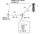
- the remote UE 1 transmits data to the relay UE 2 on the side link 201, and the relay UE 2 transmits data received from the remote UE 1 to the base station 3 on the uplink 221.
- the base station 3 determines a side link radio resource to be allocated for side link transmission from the remote UE 1 to the relay UE 2 and determines an uplink radio resource to be allocated to the uplink 221 of the relay UE 2.
- the base station 3 may determine a side link radio resource to be allocated for side link transmission from the remote UE 1 to the relay UE 2 in consideration of an uplink quality metric from the relay UE 2 to the base station 3. Good.
- the uplink quality metric of the relay UE2 relates to the performance (e.g., bandwidth or throughput) of uplink transmission from the relay UE2 to the base station 3.
- the uplink quality metric of the relay UE2 includes, for example, an estimated bandwidth of the uplink, an estimated throughput of the uplink, an estimated radio resource amount allocated to the uplink, an estimated Modulation and Coding scheme (MCS) applied to the uplink, and a relay Based on at least one of the estimated path loss from the UE 2 to the base station 3.
- the base station 3 may receive the uplink quality metric of the relay UE2 from the relay UE2. Alternatively, the base station 3 may estimate the uplink quality metric itself.
- the base station 3 ensures that the performance (eg, bandwidth or throughput) of the side link transmission from the remote UE 1 to the relay UE 2 is consistent with the performance of the uplink transmission from the relay UE 2 to the base station 3.
- radio resources to be allocated to the side link transmission may be determined.
- the base station 3 has the performance (eg, bandwidth or throughput) of one or more side link transmissions related to one relay UE2 being equal to or less than the performance of uplink transmission of the relay UE2. In this way, the radio resource to be allocated for side link transmission may be determined.
- the side link reception throughput of the relay UE 2 exceeds the uplink transmission throughput.
- the uplink throughput as estimated cannot be obtained due to the fluctuation of the quality of the uplink 221.
- the buffer amount of the uplink transmission buffer 21 in the relay UE2 increases, and in the worst case, there is a possibility that packet discard due to buffer overflow occurs.
- the uplink transmission buffer 21 is used to store data transmitted on the uplink.
- the uplink transmission buffer 21 stores uplink data waiting for transmission.
- the base station 3 transmits the band, throughput, or radio resource used for side link transmission (D2D transmission) from the remote UE 1 to the relay UE 2 from the relay UE to the base station 3. Is configured to adjust based on the amount of uplink data that is reserved in the relay UE for transmission to.
- D2D transmission side link transmission
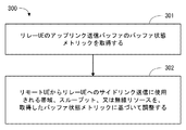
- FIG. 3 is a flowchart showing an example (processing 300) of the operation of the base station 3 according to the present embodiment.
- the base station 3 acquires the buffer status metric of the uplink transmission buffer 21 of the relay UE2.
- the buffer status metric indicates the amount of uplink data reserved in the uplink transmission buffer 21 or the occupation level of the uplink transmission buffer 21.
- the base station 3 may receive a buffer status report (buffer status information) including a buffer status metric from the relay UE2.
- the buffer status report may be sent periodically or in response to a predetermined trigger event.
- the base station 3 may calculate the buffer state metric itself. For example, the base station 3 calculates the buffer state metric of the uplink transmission buffer 630 in the relay UE2 based on the sidelink radio resource history assigned to the remote UE1 and the uplink radio resource history assigned to the relay UE2. Also good.
- the base station 3 adjusts the bandwidth, throughput, or radio resource used for side link transmission from the remote UE1 to the relay UE2 based on the acquired buffer state metric. For example, the base station 3 reduces the bandwidth, throughput, or radio resources used for side link transmission from the remote UE1 to the relay UE2 in response to an increase in the amount of uplink data reserved in the relay UE2. May be. On the contrary, the base station 3 responds to a decrease in the amount of uplink data reserved in the relay UE2 in the bandwidth, throughput, or used for the sidelink transmission from the remote UE1 to the relay UE2. Radio resources may be increased.
- the base station 3 adjusts radio resources allocated to side link transmissions from the remote UE 1 to the relay UE 2 in a scheduled resource allocation. For example, when the buffer state metric of the uplink transmission buffer 21 exceeds a predetermined threshold, the base station 3 may reduce the radio resource allocation amount for the side link transmission from the remote UE1 to the relay UE2. Specifically, in response to an increase in the amount of uplink data reserved in the relay UE2, the base station 3 reduces the radio resources allocated to the side link transmission from the remote UE1 to the relay UE2, or Allocation of radio resources for link transmission may be temporarily stopped.
- the base station 3 may lower the priority of the remote UE 1 used for side link radio resource allocation (scheduling) in response to an increase in the amount of uplink data reserved in the relay UE 2. Thereby, the bandwidth and throughput of side link transmission from the remote UE 1 to the relay UE 2 can be reduced, and therefore, it is possible to contribute to the suppression of the overflow of the uplink transmission buffer 21.
- the base station 3 may suppress transmission of a side link resource request by the remote UE 1 in response to an increase in the amount of uplink data reserved in the relay UE 2. Thereby, the bandwidth and throughput of side link transmission from the remote UE 1 to the relay UE 2 can be reduced, and therefore, it is possible to contribute to the suppression of the overflow of the uplink transmission buffer 21.
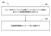
- the base station 3 may operate according to the example (processing 400) shown in FIG.
- the base station 3 generates transmission control information 230 based on the buffer state of the uplink transmission buffer 21 of the relay UE2.
- the base station 3 transmits the transmission control information 230 to the remote UE1.
- the base station 3 may transmit the transmission control information 230 periodically or aperiodically in response to a predetermined trigger event (e.g., buffer occupancy level threshold exceeded).
- the base station 3 may transmit the transmission control information 230 to the remote UE 1 in response to an increase in the amount of uplink data held in the relay UE 2.
- the transmission control information 230 may instruct the remote UE 1 that transmission of the side link resource request to the base station 3 should be suppressed.
- the transmission control information 230 may indicate a buffer status metric related to the uplink transmission buffer 21 of the relay UE2.
- the transmission control information 230 can also be called a pause signal.
- the transmission control information 230 described in the first embodiment may be transmitted from the relay UE2 to the remote UE1 instead of the base station 3. That is, the relay UE2 generates transmission control information 230 based on the buffer state of the uplink transmission buffer 21, and the generated transmission control information 230 is periodically or a predetermined trigger event (eg, exceeding the threshold of the buffer occupancy level). Depending on, it may be transmitted aperiodically.
- the transmission control information 230 may be transmitted in response to an increase in the amount of uplink data reserved in the uplink transmission buffer 21.
- the transmission control information 230 (a) reduce radio resources used for side link transmission from the remote UE1 to the relay UE2, (b) temporarily stop sidelink transmission, or (c) The remote UE 1 may be triggered to suppress transmission of the side link resource request to the base station 3.
- autonomous resource selection (sidelink transmission mode 2) is used for radio resource allocation for side link transmission.
- the base station 3 uses the SIB-18 or dedicated signaling (RRC signaling) to link the radio resource pools (PSSCH subframe pool and resource block pool) that are allowed to be used for direct transmission. Notification is made to the transmitting terminal (here, remote UE 1).
- the side link transmission terminal (remote UE1) autonomously selects a resource for side link control (PSCCH) and data (PSSCH) from the radio resource pool set by the base station 3.
- PSCCH side link control
- PSSCH data
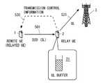
- the remote UE 1 selects a radio resource for side link transmission from the radio resource pool, and transmits data to the relay UE 2 on the side link 501 using the selected radio resource.
- the relay UE2 transmits the data received from the remote UE1 to the base station 3 on the uplink 521.
- the uplink transmission buffer 21 is used to store data transmitted on the uplink.
- the uplink transmission buffer 21 stores uplink data waiting for transmission.
- the remote UE 1 transmits the band, throughput, or radio resource used for side link transmission (D2D transmission) from the remote UE 1 to the relay UE 2 from the relay UE to the base station 3. It is configured to adjust based on the amount of uplink data reserved in the relay UE for transmission. Specifically, the remote UE 1 receives the transmission control information 530 from the relay UE 2, and adjusts the side link bandwidth, throughput, or radio resource based on the received transmission control information 530.
- the transmission control information 530 is generated based on the buffer state of the uplink transmission buffer 21 of the relay UE2.
- FIG. 6 is a flowchart showing an example of operation (process 600) of the remote UE 1 according to the present embodiment.
- Step 601 the transmission control information 530 generated based on the buffer state of the uplink transmission buffer 21 of the relay UE2 is received.
- the remote UE 1 adjusts the bandwidth, throughput, or radio resource used for side link transmission from the remote UE 1 to the relay UE 2 based on the received transmission control information 530. For example, in response to an increase in the amount of uplink data reserved in the relay UE2, the remote UE1 reduces the bandwidth, throughput, or radio resources used for sidelink transmission from the remote UE1 to the relay UE2. Also good. On the other hand, the remote UE1 responds to a decrease in the amount of uplink data held in the relay UE2 in the band, throughput, or radio used for the sidelink transmission from the remote UE1 to the relay UE2. Resources may be increased.
- FIG. 7 is a flowchart showing an example (processing 700) of the operation of the relay UE2 according to the present embodiment.
- the relay UE2 In Step 701, the relay UE2 generates transmission control information 530 based on the buffer state of the uplink transmission buffer 21.
- the relay UE2 transmits the generated transmission control information 530 to the remote UE1.
- the transmission control information 530 may indicate a buffer state metric for the uplink transmission buffer 21 of the relay UE2.
- the remote UE 1 determines an uplink estimated band or estimated throughput from the relay UE 2 to the base station 3 based on the transmission control information 530 (ie, buffer state metric), and determines the determined uplink estimated band or estimated throughput. May be used to adjust the side link bandwidth, throughput, or radio resource.
- the remote UE 1 may determine radio resources to be allocated to side link transmission so that the side link band or throughput is equal to or less than the uplink estimated band or throughput. Thereby, the bandwidth and throughput of side link transmission from the remote UE 1 to the relay UE 2 can be reduced, and therefore, it is possible to contribute to the suppression of the overflow of the uplink transmission buffer 21.
- the transmission control information 530 may be transmitted in response to an increase in the amount of uplink data reserved in the relay UE2.
- the transmission control information 530 may request the remote UE 1 to reduce the side link bandwidth, throughput, or radio resource.
- the transmission control information 530 may indicate a buffer status metric regarding the uplink transmission buffer 21.
- the transmission control information 530 triggers the remote UE1 to (a) reduce radio resources used for sidelink transmission from the remote UE1 to the relay UE2, or (b) temporarily stop the sidelink transmission. May be.
- the transmission control information 530 can also be called a pause signal. Thereby, the bandwidth and throughput of side link transmission from the remote UE 1 to the relay UE 2 can be reduced, and therefore, it is possible to contribute to the suppression of the overflow of the uplink transmission buffer 21.
- the transmission control information 530 described in the second embodiment may be transmitted from the base station 3 to the remote UE 1 instead of the relay UE 2. That is, the base station 3 generates transmission control information 530 based on the buffer state of the uplink transmission buffer 21, and the generated transmission control information 530 is periodically or predetermined trigger event (eg, a buffer occupancy level exceeding the threshold value). ) May be transmitted aperiodically. Alternatively, the base station 3 may receive the transmission control information 530 from the relay UE2 and transfer the transmission control information 530 received from the relay UE2 to the remote UE1.
- the base station 3 may receive the transmission control information 530 from the relay UE2 and transfer the transmission control information 530 received from the relay UE2 to the remote UE1.
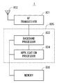
- FIG. 8 is a block diagram illustrating a configuration example of the remote UE 1.
- the relay UE2 may also have the same configuration as that shown in FIG.
- the Radio-Frequency (RF) transceiver 801 performs analog RF signal processing to communicate with the base station 3.
- Analog RF signal processing performed by the RF transceiver 801 includes frequency up-conversion, frequency down-conversion, and amplification.
- RF transceiver 801 is coupled with antenna 802 and baseband processor 803.
- the RF transceiver 801 receives modulation symbol data (or OFDM symbol data) from the baseband processor 803, generates a transmission RF signal, and supplies the transmission RF signal to the antenna 802. Further, the RF transceiver 801 generates a baseband received signal based on the received RF signal received by the antenna 802 and supplies this to the baseband processor 803.
- the RF transceiver 801 may also be used for side link communication with other UEs.
- the RF transceiver 801 may include a plurality of transceivers.
- the baseband processor 803 performs digital baseband signal processing (data plane processing) and control plane processing for wireless communication.
- Digital baseband signal processing consists of (a) data compression / decompression, (b) data segmentation / concatenation, (c) ⁇ transmission format (transmission frame) generation / decomposition, and (d) transmission path encoding / decoding. , (E) modulation (symbol mapping) / demodulation, and (f) generation of OFDM symbol data (baseband OFDM signal) by Inverse Fast Fourier Transform (IFFT).
- control plane processing includes layer 1 (eg, transmission power control), layer 2 (eg, radio resource management, hybrid automatic repeat request (HARQ) processing), and layer 3 (eg, attach, mobility, and call management). Communication management).
- the digital baseband signal processing by the baseband processor 803 includes signal processing of the Packet Data Convergence Protocol (PDCP) layer, Radio Link Control (RLC) layer, MAC layer, and PHY layer. But you can.
- the control plane processing by the baseband processor 803 may include Non-Access Stratum (NAS) protocol, RRC protocol, and MAC CE processing.
- NAS Non-Access Stratum
- the baseband processor 803 includes a modem processor (eg, Digital Signal Processor (DSP)) that performs digital baseband signal processing and a protocol stack processor (eg, Central Processing Unit (CPU), or Micro Processing Unit that performs control plane processing. (MPU)).
- DSP Digital Signal Processor
- MPU Micro Processing Unit that performs control plane processing.
- a protocol stack processor that performs control plane processing may be shared with an application processor 804 described later.
- Application processor 804 is also referred to as a CPU, MPU, microprocessor, or processor core.
- the application processor 804 may include a plurality of processors (a plurality of processor cores).
- the application processor 804 is a system software program (Operating System (OS)) read from the memory 806 or a memory (not shown) and various application programs (for example, call application, web browser, mailer, camera operation application, music playback) By executing the application, various functions of the remote UE 1 are realized.
- OS Operating System
- the baseband processor 803 and the application processor 804 may be integrated on a single chip, as shown by the dashed line (805) in FIG.
- the baseband processor 803 and the application processor 804 may be implemented as one System on Chip (SoC) device 805.
- SoC System on Chip
- An SoC device is sometimes called a system Large Scale Integration (LSI) or chipset.
- the memory 806 is a volatile memory, a nonvolatile memory, or a combination thereof.
- the memory 806 may include a plurality of physically independent memory devices.
- the volatile memory is, for example, Static Random Access Memory (SRAM), Dynamic RAM (DRAM), or a combination thereof.
- the non-volatile memory is a mask Read Only Memory (MROM), Electrically Erasable Programmable ROM (EEPROM), flash memory, hard disk drive, or any combination thereof.
- the memory 806 may include an external memory device accessible from the baseband processor 803, the application processor 804, and the SoC 805.
- Memory 806 may include an embedded memory device integrated within baseband processor 803, application processor 804, or SoC 805.
- the memory 806 may include a memory in a Universal Integrated Circuit Card (UICC).
- UICC Universal Integrated Circuit Card
- the memory 806 may store a software module (computer program) including an instruction group and data for performing processing by the remote UE 1 described in the plurality of embodiments described above.
- the baseband processor 803 or the application processor 804 is configured to read out and execute the software module from the memory 806 to perform the processing of the remote UE 1 described using the drawings in the above-described embodiment. May be.
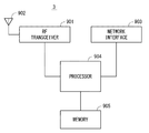
- FIG. 9 is a block diagram illustrating a configuration example of the base station 3 according to the above-described embodiment.
- the base station 3 includes an RF transceiver 901, a network interface 903, a processor 904, and a memory 905.
- the RF transceiver 901 performs analog RF signal processing to communicate with the remote UE1 and the relay UE2.
- the RF transceiver 901 may include multiple transceivers.
- RF transceiver 901 is coupled with antenna 902 and processor 904.
- the RF transceiver 901 receives modulation symbol data (or OFDM symbol data) from the processor 904, generates a transmission RF signal, and supplies the transmission RF signal to the antenna 902. Further, the RF transceiver 901 generates a baseband received signal based on the received RF signal received by the antenna 902 and supplies this to the processor 904.
- the network interface 903 is used to communicate with network nodes (e.g., Mobility Management Entity (MME) and Serving Gateway (S-GW)).
- MME Mobility Management Entity
- S-GW Serving Gateway
- the network interface 903 may include, for example, a network interface card (NIC) compliant with IEEE 802.3 series.
- NIC network interface card
- the processor 904 performs digital baseband signal processing (data plane processing) and control plane processing for wireless communication.
- the digital baseband signal processing by the processor 904 may include PDCP layer, RLC layer, MAC layer, and PHY layer signal processing.
- the control plane processing by the processor 904 may include S1 protocol, RRC protocol, and MAC-CE processing.
- the processor 904 may include a plurality of processors.
- the processor 904 may include a modem processor (e.g., DSP) that performs digital baseband signal processing and a protocol stack processor (e.g., CPU or MPU) that performs control plane processing.
- DSP digital baseband signal processing
- protocol stack processor e.g., CPU or MPU
- the memory 905 is configured by a combination of a volatile memory and a nonvolatile memory.
- the volatile memory is, for example, SRAM or DRAM or a combination thereof.
- the non-volatile memory is, for example, an MROM, PROM, flash memory, hard disk drive, or a combination thereof.
- Memory 905 may include storage located remotely from processor 904. In this case, the processor 904 may access the memory 905 via the network interface 903 or an I / O interface not shown.
- the memory 905 may store a software module (computer program) including an instruction group and data for performing processing by the base station 3 described in the plurality of embodiments.
- the processor 904 may be configured to perform the processing of the base station 3 described with reference to the drawings in the above-described embodiment by reading the software module from the memory 905 and executing the software module.
- each of the processors included in the remote UE 1, the relay UE 2, and the base station 3 causes the computer to execute the algorithm described with reference to the drawings.
- One or a plurality of programs including the instruction group is executed.
- the program can be stored and supplied to a computer using various types of non-transitory computer readable media.
- Non-transitory computer readable media include various types of tangible storage media (tangible storage medium).
- non-transitory computer-readable media are magnetic recording media (eg flexible disks, magnetic tapes, hard disk drives), magneto-optical recording media (eg magneto-optical discs), Compact Disc Read Only Memory (CD-ROM), CD-ROM R, CD-R / W, semiconductor memory (for example, mask ROM, Programmable ROM (PROM), Erasable PROM (EPROM), flash ROM, Random Access Memory (RAM)).
- the program may also be supplied to the computer by various types of temporary computer-readable media. Examples of transitory computer readable media include electrical signals, optical signals, and electromagnetic waves.
- the temporary computer-readable medium can supply the program to the computer via a wired communication path such as an electric wire and an optical fiber, or a wireless communication path.
- the processing and operation performed by the base station 3 including the allocation of the side link radio resource described in the above-described embodiment is the Digital Unit (DU) or DU and Radio Unit included in the Cloud Radio Access Network (C-RAN) architecture.
- RU may be provided in combination.
- DU is called Baseband Unit (BBU).
- RU is also called Remote Radio Head (RRH) or Remote Radio Equipment (RRE). That is, the process and operation performed by the base station 3 described in the above embodiment may be provided by any one or a plurality of radio stations (RAN nodes).
- (Appendix 1) Memory At least one processor coupled to the memory; With The at least one processor is configured to transmit a band, throughput, or radio resource used for device-to-device (D2D) transmission from a remote terminal to a relay terminal, from the relay terminal to the base station. Configured to adjust based on the amount of uplink data pending in An apparatus for controlling device-to-device communication.
- D2D device-to-device
- the at least one processor receives buffer status information indicating a buffer status metric related to an amount of data in an uplink transmission buffer of the relay terminal or an occupation level of the uplink transmission buffer, and based on the buffer status information, the bandwidth Configured to adjust the throughput, or the radio resource, The apparatus according to appendix 1.
- the at least one processor determines an uplink estimated band or estimated throughput from the relay terminal to the base station based on the buffer state information, and uses the estimated band or estimated throughput for the D2D transmission Configured to adjust the bandwidth, the throughput, or the radio resource to be The apparatus according to appendix 2.
- the at least one processor is configured to reduce the bandwidth, the throughput, or the radio resource used for the D2D transmission in response to an increase in the amount of reserved uplink data.
- the apparatus according to any one of appendices 1 to 3.
- the at least one processor is responsive to an increase in the amount of reserved uplink data, (a) reducing radio resources used for D2D transmission from the remote terminal to the relay terminal; (b) The D2D transmission is temporarily stopped, or (c) the transmission of the D2D resource request to the base station is suppressed.
- the apparatus according to appendix 5.
- Appendix 7 The apparatus is implemented in the base station; The apparatus according to any one of appendices 1 to 4.
- the at least one processor is responsive to an increase in the amount of reserved uplink data, (a) reducing radio resources allocated for D2D transmission from the remote terminal to the relay terminal; (b) the D2D Temporarily stop allocation of the radio resource to transmission, (c) lower the priority of the remote terminal used for D2D radio resource allocation, or (d) inhibit transmission of the D2D resource request by the remote terminal To be configured,
- the bandwidth, throughput, or radio resource used for device-to-device (D2D) transmission from the remote terminal to the relay terminal is reserved in the relay terminal for transmission from the relay terminal to the base station Comprising adjusting based on the amount of link data; A method for controlling device-to-device communication.
- D2D device-to-device
- a program for causing a computer to perform a method for controlling device-to-device communication The method reserves bandwidth, throughput, or radio resources used for device-to-device (D2D) transmission from a remote terminal to a relay terminal within the relay terminal for transmission from the relay terminal to a base station. Including adjusting based on the amount of uplink data being program.
- D2D device-to-device
- control information is used by the remote terminal to adjust the bandwidth, throughput, or radio resources used for D2D transmission from the remote terminal to the relay terminal.
- the base station according to attachment 11.
- the control information indicates a buffer state metric related to the amount of uplink data reserved or the occupation level of the uplink transmission buffer.
- the base station according to Appendix 11 or 12.
- the control information is transmitted in response to an increase in the amount of reserved uplink data,
- the control information includes (a) reducing radio resources used for D2D transmission from the remote terminal to the relay terminal, (b) temporarily stopping the D2D transmission, or (c) a D2D resource request. Deterring transmission to the base station to the remote terminal, 14.
- the base station according to any one of appendices 11 to 13.
- the control information indicates that the base station refuses to allocate radio resources for D2D transmission from the remote terminal to the relay terminal. 14. The base station according to any one of appendices 11 to 13.
- Appendix 17 A program for causing a computer to perform a method in a base station, The method Obtaining a buffer state of an uplink transmission buffer for storing uplink data reserved in the relay terminal for transmission from the relay terminal to the base station; and a device tool generated based on the buffer state Sending device (D2D) control information to the remote terminal; Including the program.
- D2D buffer state Sending device
- control information is used by the remote terminal to adjust the bandwidth, throughput, or radio resources used for D2D transmission from the remote terminal to the relay terminal.
- the relay terminal according to appendix 18.
- the control information indicates a buffer state metric related to the amount of uplink data reserved or the occupation level of the uplink transmission buffer.
- the relay terminal according to appendix 18 or 19.
- the control information is transmitted in response to an increase in the amount of reserved uplink data,
- the control information includes (a) reducing radio resources used for D2D transmission from the remote terminal to the relay terminal, (b) temporarily stopping the D2D transmission, or (c) a D2D resource request. Deterring transmission to the base station to the remote terminal, The relay terminal according to any one of appendices 18 to 20.
- the at least one processor is configured to send the control information to the remote terminal over a D2D link;
- the relay terminal according to any one of appendices 18 to 21.
- Appendix 24 A program for causing a computer to perform a method in a relay terminal, The method Obtaining a buffer state of an uplink transmission buffer for storing uplink data held in the relay terminal for transmission from the relay terminal to a base station; and control information generated based on the buffer state To the remote terminal, Including the program.
- the at least one processor is configured to adjust a bandwidth, throughput, or radio resource used for D2D transmission from the remote terminal to the relay terminal based on the control information.
- the remote terminal according to attachment 25.
- the control information indicates a buffer state metric related to the amount of uplink data reserved or the occupation level of the uplink transmission buffer.
- the remote terminal according to appendix 25 or 26.
- the at least one processor determines an uplink estimated band or estimated throughput from the relay terminal to the base station based on the control information, and is used for the D2D transmission in consideration of the estimated band or estimated throughput. Configured to adjust bandwidth, throughput, or radio resources, The remote terminal according to appendix 27.
- the control information is transmitted in response to an increase in the amount of reserved uplink data,
- the control information includes (a) reducing radio resources used for D2D transmission from the remote terminal to the relay terminal, (b) temporarily stopping the D2D transmission, or (c) a D2D resource request. Deterring transmission to the base station to the remote terminal, 28.
- the remote terminal according to any one of appendices 25 to 27.
- the at least one processor is configured to receive the control information from the relay terminal over a D2D link; Item 30.
- the remote terminal according to any one of appendices 25 to 29.
- a method comprising:
- Appendix 32 Adjusting the bandwidth, throughput, or radio resource used for D2D transmission from the remote terminal to the relay terminal based on the control information; The method according to appendix 31.
- Appendix 33 A program for causing a computer to perform a method in a remote terminal, In the method, control information generated based on a buffer state of an uplink transmission buffer storing uplink data reserved in the relay terminal for transmission from the relay terminal to the base station is transmitted to the remote terminal or the Including receiving from the base station, program.
Landscapes
- Engineering & Computer Science (AREA)
- Computer Networks & Wireless Communication (AREA)
- Signal Processing (AREA)
- Mobile Radio Communication Systems (AREA)
Abstract
L'invention concerne un dispositif (1 ou 3) qui ajuste la bande, le débit ou les ressources radio utilisées dans une transmission de dispositif à dispositif d'un terminal distant (1) à un terminal de relais (2) sur la base de la quantité de données de liaison montante contenues dans le terminal de relais (2) pour la transmission du terminal de relais (2) à une station de base (3). Par ce moyen, il est possible de contribuer, par exemple, à éviter une incohérence de performance entre une transmission de liaison latérale du terminal distant au terminal relais et une transmission de liaison montante du terminal relais à la station de base.
Priority Applications (2)
| Application Number | Priority Date | Filing Date | Title |
|---|---|---|---|
| JP2018507057A JP7044057B2 (ja) | 2016-03-23 | 2017-01-12 | デバイス・ツー・デバイス通信を制御するための装置及びその方法 |
| US16/086,183 US11071119B2 (en) | 2016-03-23 | 2017-01-12 | Apparatus for controlling device-to-device communication, base station, radio terminal, and method therefor |
Applications Claiming Priority (2)
| Application Number | Priority Date | Filing Date | Title |
|---|---|---|---|
| JP2016058488 | 2016-03-23 | ||
| JP2016-058488 | 2016-03-23 |
Publications (1)
| Publication Number | Publication Date |
|---|---|
| WO2017163544A1 true WO2017163544A1 (fr) | 2017-09-28 |
Family
ID=59901053
Family Applications (1)
| Application Number | Title | Priority Date | Filing Date |
|---|---|---|---|
| PCT/JP2017/000755 Ceased WO2017163544A1 (fr) | 2016-03-23 | 2017-01-12 | Dispositif de commande de communication de dispositif à dispositif, station de base, terminal radio et procédé associé à ceux-ci |
Country Status (3)
| Country | Link |
|---|---|
| US (1) | US11071119B2 (fr) |
| JP (1) | JP7044057B2 (fr) |
| WO (1) | WO2017163544A1 (fr) |
Cited By (4)
| Publication number | Priority date | Publication date | Assignee | Title |
|---|---|---|---|---|
| JP2019176266A (ja) * | 2018-03-27 | 2019-10-10 | 株式会社Kddi総合研究所 | リソース制御装置、リソース制御方法及びリソース制御プログラム |
| CN112262604A (zh) * | 2018-10-19 | 2021-01-22 | Oppo广东移动通信有限公司 | 一种车联网连接配置方法、终端及存储介质 |
| KR20220088439A (ko) * | 2020-02-12 | 2022-06-27 | 애플 인크. | 자원 재선택 및 선점 방법들 |
| CN114731174A (zh) * | 2019-12-31 | 2022-07-08 | 华为技术有限公司 | 无线通信方法及通信装置 |
Families Citing this family (12)
| Publication number | Priority date | Publication date | Assignee | Title |
|---|---|---|---|---|
| EP3669605A4 (fr) * | 2017-08-18 | 2021-01-20 | Lenovo (Beijing) Limited | Procédé et appareil de communication en liaison latérale |
| KR102505060B1 (ko) * | 2018-01-12 | 2023-03-02 | 삼성전자주식회사 | 무선 통신 시스템에서 스케줄링을 위한 장치 및 방법 |
| US11212773B2 (en) * | 2018-06-27 | 2021-12-28 | Qualcomm Incorporated | Communication of sidelink transmission pattern to wireless wide area network (WWAN) |
| JP7101595B2 (ja) * | 2018-11-05 | 2022-07-15 | 住友電気工業株式会社 | スイッチ装置、通信制御方法および通信制御プログラム |
| US11476899B2 (en) * | 2019-04-18 | 2022-10-18 | Huawei Technologies Co., Ltd. | Uplink multi-user equipment (UE) cooperative transmission |
| WO2020226386A1 (fr) * | 2019-05-03 | 2020-11-12 | 엘지전자 주식회사 | Procédé de transmission de signal de liaison latérale dans un système de communication sans fil |
| US11871454B2 (en) * | 2019-07-19 | 2024-01-09 | Qualcomm Incorporated | Handling collisions between access link and sidelink |
| US11943067B2 (en) * | 2019-10-04 | 2024-03-26 | Huawei Technologies Co., Ltd. | Devices and methods of signaling for resource selection and reservation in sidelink transmission |
| US11917605B2 (en) * | 2019-11-05 | 2024-02-27 | Qualcomm Incorporated | Multi-path diversity for uplink transmissions through sidelinks |
| WO2021193178A1 (fr) * | 2020-03-25 | 2021-09-30 | 京セラ株式会社 | Procédé de commande de communication et dispositif d'utilisateur relais |
| WO2023044826A1 (fr) * | 2021-09-24 | 2023-03-30 | Apple Inc. | Agrégation d'équipements utilisateur pour communications en liaison montante |
| EP4458107A4 (fr) * | 2021-12-31 | 2025-08-13 | Qualcomm Inc | Découverte d'équipement d'utilisateur distant et établissement de liaison pour un équipement d'utilisateur à capacité réduite |
Citations (5)
| Publication number | Priority date | Publication date | Assignee | Title |
|---|---|---|---|---|
| WO2011007388A1 (fr) * | 2009-07-15 | 2011-01-20 | 富士通株式会社 | Système de communication radio, dispositif de station de base, dispositif terminal, dispositif de station relais et procédé de communication radio dans un système de communication radio |
| JP2011097340A (ja) * | 2009-10-29 | 2011-05-12 | Mitsubishi Electric Corp | 無線通信システム、リレー局および無線リソース制御方法 |
| JP2013030908A (ja) * | 2011-07-27 | 2013-02-07 | Kyocera Corp | 無線中継装置および無線通信方法 |
| JP2013524643A (ja) * | 2010-04-02 | 2013-06-17 | インターデイジタル パテント ホールディングス インコーポレイテッド | 中継ノードを介した通信をサポートするための方法および装置 |
| WO2015046155A1 (fr) * | 2013-09-27 | 2015-04-02 | 京セラ株式会社 | Procédé de commande de transmission |
Family Cites Families (22)
| Publication number | Priority date | Publication date | Assignee | Title |
|---|---|---|---|---|
| US8462743B2 (en) * | 2008-01-25 | 2013-06-11 | Nokia Siemens Networks Oy | Method, apparatus and computer program for signaling channel quality information in a network that employs relay nodes |
| US8576714B2 (en) * | 2009-05-29 | 2013-11-05 | Futurewei Technologies, Inc. | System and method for relay node flow control in a wireless communications system |
| US8543054B2 (en) * | 2010-05-03 | 2013-09-24 | Telefonaktiebolaget L M Ericsson (Publ) | Method and apparatus for uplink scheduling using relays |
| US8811306B2 (en) * | 2010-06-22 | 2014-08-19 | Futurewei Technologies, Inc. | System and method for scheduling in a multi-hop environment |
| US9160662B2 (en) * | 2010-08-20 | 2015-10-13 | Google Technology Holdings LLC | Uplink buffer status reporting of relay stations in wireless networks |
| US8948006B2 (en) * | 2013-01-07 | 2015-02-03 | Freescale Semiconductor, Inc. | System for managing uplink quality of service (QoS) in cellular network |
| US9961719B2 (en) * | 2013-03-11 | 2018-05-01 | Zte Corporation | Integrated relay in wireless communication networks |
| US9949246B2 (en) * | 2013-09-27 | 2018-04-17 | Telefonaktiebolaget Lm Ericsson (Publ) | Device to device (D2D) control information relay |
| JP6488238B2 (ja) * | 2013-12-20 | 2019-03-20 | 京セラ株式会社 | 移動通信システム、無線通信装置、ネットワーク装置、及び無線端末 |
| US9954605B2 (en) * | 2014-07-10 | 2018-04-24 | Sony Corporation | Telecommunications apparatus and methods |
| US10064035B2 (en) * | 2014-11-07 | 2018-08-28 | Nokia Technologies Oy | Device-to-device (D2D) resource release |
| CN107079380A (zh) * | 2014-11-14 | 2017-08-18 | 株式会社Ntt都科摩 | 用户装置及d2d通信方法 |
| JPWO2016142973A1 (ja) * | 2015-03-06 | 2017-12-21 | 日本電気株式会社 | 近接サービス通信のための装置及び方法 |
| CN106465225A (zh) * | 2015-04-03 | 2017-02-22 | 华为技术有限公司 | 数据传输的方法、用户设备和基站 |
| US10356656B2 (en) * | 2015-04-07 | 2019-07-16 | Lg Electronics Inc. | Method and apparatus for performing buffer status reporting procedure for relaying in wireless communication system |
| US9942917B2 (en) * | 2015-05-14 | 2018-04-10 | Blackberry Limited | Allocating resources for a device-to-device transmission |
| US10064212B2 (en) * | 2015-05-14 | 2018-08-28 | Blackberry Limited | Transmitting a scheduling request for a device-to-device transmission |
| EP3125643B1 (fr) * | 2015-07-31 | 2019-04-03 | Panasonic Intellectual Property Corporation of America | Système d'allocation de resources amélioré pour des équipements utilisateurs agissant en relais de communication pour d'autres equipments distants |
| EP3148283A1 (fr) * | 2015-09-25 | 2017-03-29 | ASUSTek Computer Inc. | Procédé et appareil de réduction du surdébit de signalisation dans un réseau de communication sans fil |
| US10187810B1 (en) * | 2015-11-16 | 2019-01-22 | Sprint Spectrum L.P. | Dynamically prioritizing network traffic |
| WO2017113130A1 (fr) * | 2015-12-29 | 2017-07-06 | 华为技术有限公司 | Procédé de demande de ressources, nœud côté réseau et système |
| EP3420763B1 (fr) * | 2016-02-25 | 2021-05-26 | Nokia Solutions and Networks Oy | Procedes et appareils pour attribuer des resources en se basant sur une carte de priorites |
-
2017
- 2017-01-12 WO PCT/JP2017/000755 patent/WO2017163544A1/fr not_active Ceased
- 2017-01-12 US US16/086,183 patent/US11071119B2/en active Active
- 2017-01-12 JP JP2018507057A patent/JP7044057B2/ja active Active
Patent Citations (5)
| Publication number | Priority date | Publication date | Assignee | Title |
|---|---|---|---|---|
| WO2011007388A1 (fr) * | 2009-07-15 | 2011-01-20 | 富士通株式会社 | Système de communication radio, dispositif de station de base, dispositif terminal, dispositif de station relais et procédé de communication radio dans un système de communication radio |
| JP2011097340A (ja) * | 2009-10-29 | 2011-05-12 | Mitsubishi Electric Corp | 無線通信システム、リレー局および無線リソース制御方法 |
| JP2013524643A (ja) * | 2010-04-02 | 2013-06-17 | インターデイジタル パテント ホールディングス インコーポレイテッド | 中継ノードを介した通信をサポートするための方法および装置 |
| JP2013030908A (ja) * | 2011-07-27 | 2013-02-07 | Kyocera Corp | 無線中継装置および無線通信方法 |
| WO2015046155A1 (fr) * | 2013-09-27 | 2015-04-02 | 京セラ株式会社 | Procédé de commande de transmission |
Non-Patent Citations (2)
| Title |
|---|
| COOLPAD: "Further Discussion on Resource Allocation Issues and Way Forward for Release 13", 3GPP TSG-RAN WG2#91BIS R2-154269, 25 September 2015 (2015-09-25), XP051004828, Retrieved from the Internet <URL:http://www.3gpp.org/ftp/tsg_ran/WG2_RL2/TSGR2_91bis/DOCS/R2-154269.zip> * |
| KYOCERA: "Resource allocation schemes for D2D communication", 3GPP TSG-RAN WG2#84 3GPP TSG-RAN WG2#84 R2-134311, 1 November 2013 (2013-11-01), XP050737039, Retrieved from the Internet <URL:http://www.3gpp.org/ftp/tsg_ran/WG2_RL2/TSGR2_84/Docs/R2-134311.zip> * |
Cited By (5)
| Publication number | Priority date | Publication date | Assignee | Title |
|---|---|---|---|---|
| JP2019176266A (ja) * | 2018-03-27 | 2019-10-10 | 株式会社Kddi総合研究所 | リソース制御装置、リソース制御方法及びリソース制御プログラム |
| CN112262604A (zh) * | 2018-10-19 | 2021-01-22 | Oppo广东移动通信有限公司 | 一种车联网连接配置方法、终端及存储介质 |
| CN114731174A (zh) * | 2019-12-31 | 2022-07-08 | 华为技术有限公司 | 无线通信方法及通信装置 |
| KR20220088439A (ko) * | 2020-02-12 | 2022-06-27 | 애플 인크. | 자원 재선택 및 선점 방법들 |
| KR102867169B1 (ko) | 2020-02-12 | 2025-10-01 | 애플 인크. | 자원 재선택 및 선점 방법들 |
Also Published As
| Publication number | Publication date |
|---|---|
| US20200305165A1 (en) | 2020-09-24 |
| JPWO2017163544A1 (ja) | 2019-01-31 |
| JP7044057B2 (ja) | 2022-03-30 |
| US11071119B2 (en) | 2021-07-20 |
Similar Documents
| Publication | Publication Date | Title |
|---|---|---|
| JP7044057B2 (ja) | デバイス・ツー・デバイス通信を制御するための装置及びその方法 | |
| US11452118B2 (en) | Apparatus and method for controlling device-to-device communication | |
| JP7810439B2 (ja) | 端末装置の方法および端末装置 | |
| JP7010227B2 (ja) | 無線通信のための装置、方法、及びプログラム | |
| JP6822418B2 (ja) | ネットワーク装置、無線端末、及びこれらの方法 | |
| JP6610656B2 (ja) | 近接サービス通信のための装置及び方法 | |
| JP6908054B2 (ja) | 無線通信のための無線端末、無線通信システム、及びプログラム | |
| US20200296745A1 (en) | Apparatus and method for resource scheduling related to device-to-device communication | |
| JP6631351B2 (ja) | デバイス・ツー・デバイス通信に関するリソーススケジューリングのための装置及び方法 | |
| JPWO2017002282A1 (ja) | 無線通信のための方法及び装置 | |
| WO2017187713A1 (fr) | Appareil et procédé destinés à la communication sans fil | |
| JP6696504B2 (ja) | 無線端末装置、ネットワークノード、及び方法 | |
| US10420124B2 (en) | Remote node, center node, communication system, communication terminal, and communication method | |
| US20250110098A1 (en) | Terminal, base station, and method for the same |
Legal Events
| Date | Code | Title | Description |
|---|---|---|---|
| WWE | Wipo information: entry into national phase |
Ref document number: 2018507057 Country of ref document: JP |
|
| NENP | Non-entry into the national phase |
Ref country code: DE |
|
| 121 | Ep: the epo has been informed by wipo that ep was designated in this application |
Ref document number: 17769591 Country of ref document: EP Kind code of ref document: A1 |
|
| 122 | Ep: pct application non-entry in european phase |
Ref document number: 17769591 Country of ref document: EP Kind code of ref document: A1 |