WO2017163563A1 - Unité d'échangeur de chaleur et dispositif de climatisation d'air pour véhicule - Google Patents
Unité d'échangeur de chaleur et dispositif de climatisation d'air pour véhicule Download PDFInfo
- Publication number
- WO2017163563A1 WO2017163563A1 PCT/JP2017/001642 JP2017001642W WO2017163563A1 WO 2017163563 A1 WO2017163563 A1 WO 2017163563A1 JP 2017001642 W JP2017001642 W JP 2017001642W WO 2017163563 A1 WO2017163563 A1 WO 2017163563A1
- Authority
- WO
- WIPO (PCT)
- Prior art keywords
- refrigerant
- heat exchanger
- heat
- coolant
- heat exchange
- Prior art date
- Legal status (The legal status is an assumption and is not a legal conclusion. Google has not performed a legal analysis and makes no representation as to the accuracy of the status listed.)
- Ceased
Links
Images


Classifications
-
- B—PERFORMING OPERATIONS; TRANSPORTING
- B60—VEHICLES IN GENERAL
- B60H—ARRANGEMENTS OF HEATING, COOLING, VENTILATING OR OTHER AIR-TREATING DEVICES SPECIALLY ADAPTED FOR PASSENGER OR GOODS SPACES OF VEHICLES
- B60H1/00—Heating, cooling or ventilating devices
- B60H1/00642—Control systems or circuits; Control members or indication devices for heating, cooling or ventilating devices
- B60H1/00814—Control systems or circuits characterised by their output, for controlling particular components of the heating, cooling or ventilating installation
- B60H1/00878—Control systems or circuits characterised by their output, for controlling particular components of the heating, cooling or ventilating installation the components being temperature regulating devices
- B60H1/00899—Controlling the flow of liquid in a heat pump system
-
- B—PERFORMING OPERATIONS; TRANSPORTING
- B60—VEHICLES IN GENERAL
- B60H—ARRANGEMENTS OF HEATING, COOLING, VENTILATING OR OTHER AIR-TREATING DEVICES SPECIALLY ADAPTED FOR PASSENGER OR GOODS SPACES OF VEHICLES
- B60H1/00—Heating, cooling or ventilating devices
- B60H1/32—Cooling devices
- B60H1/3204—Cooling devices using compression
- B60H1/3228—Cooling devices using compression characterised by refrigerant circuit configurations
- B60H1/32284—Cooling devices using compression characterised by refrigerant circuit configurations comprising two or more secondary circuits, e.g. at evaporator and condenser side
-
- F—MECHANICAL ENGINEERING; LIGHTING; HEATING; WEAPONS; BLASTING
- F25—REFRIGERATION OR COOLING; COMBINED HEATING AND REFRIGERATION SYSTEMS; HEAT PUMP SYSTEMS; MANUFACTURE OR STORAGE OF ICE; LIQUEFACTION SOLIDIFICATION OF GASES
- F25B—REFRIGERATION MACHINES, PLANTS OR SYSTEMS; COMBINED HEATING AND REFRIGERATION SYSTEMS; HEAT PUMP SYSTEMS
- F25B39/00—Evaporators; Condensers
- F25B39/04—Condensers
-
- B—PERFORMING OPERATIONS; TRANSPORTING
- B60—VEHICLES IN GENERAL
- B60H—ARRANGEMENTS OF HEATING, COOLING, VENTILATING OR OTHER AIR-TREATING DEVICES SPECIALLY ADAPTED FOR PASSENGER OR GOODS SPACES OF VEHICLES
- B60H1/00—Heating, cooling or ventilating devices
- B60H1/00642—Control systems or circuits; Control members or indication devices for heating, cooling or ventilating devices
- B60H1/00814—Control systems or circuits characterised by their output, for controlling particular components of the heating, cooling or ventilating installation
- B60H1/00878—Control systems or circuits characterised by their output, for controlling particular components of the heating, cooling or ventilating installation the components being temperature regulating devices
- B60H2001/00928—Control systems or circuits characterised by their output, for controlling particular components of the heating, cooling or ventilating installation the components being temperature regulating devices comprising a secondary circuit
Definitions
- This disclosure relates to a heat exchange unit and a vehicle air conditioner.
- a vehicle air conditioner system includes a compressor (compressor) that sucks / compresses refrigerant to generate a high pressure, and a condenser that liquefies the refrigerant by exchanging heat with the other medium (generally air).
- compressor compressor
- Condenser a receiver that stores the liquefied refrigerant
- expansion valve that adiabatically expands the refrigerant to make the refrigerant low pressure and low temperature
- heat exchange of the refrigerant with another medium generally air
- a closed circuit is formed by an evaporator (evaporator) for vaporizing the refrigerant and a pipe connecting them.
- Patent Document 1 discloses a first heat radiating unit that is connected to a radiator to circulate cooling water, circulates refrigerant discharged by a compressor, and condenses the refrigerant by heat exchange between the cooling water and the refrigerant.
- a vehicle in which a second heat dissipating part that cools the condensed refrigerant that has been cooled and condensed by the first heat dissipating part and a receiver driver part that performs gas-liquid separation of the refrigerant and further removes moisture from the condensed refrigerant are integrally formed.
- a capacitor is disclosed.
- the receiver driver unit also plays a role of storing the liquid refrigerant and adjusting the amount of the circulating refrigerant.
- a heat exchange unit is configured by sandwiching a plurality of plates between two panels, and performs heat exchange between an air-conditioning refrigerant flowing between the plates and a coolant that cools a heat-generating component.
- the heat exchanger and the tank are integrated, and the tank is fixed to a region on the surface of one of the two panels. .
- a vehicle air conditioner includes a compressor that compresses a refrigerant, a heater core that heats air that is sent into the vehicle interior by a coolant that is warmed by heat exchange with the compressed refrigerant, A heat exchanger configured by sandwiching a plurality of plates between two panels and performing heat exchange between a refrigerant for air conditioning flowing between the plates and a coolant for cooling the heat generating component; and a tank for storing the refrigerant.
- the heat exchanger and the tank are integrated, and the tank is fixed to a region on the surface of one of the two panels.
- the heat exchange unit and the vehicle air conditioner of the present disclosure it is possible to easily secure the volume necessary for storing the refrigerant, to easily change the stored volume, and to secure sufficient strength. .
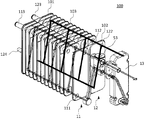
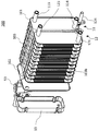
- the perspective view which shows an example of the heat exchange unit which concerns on embodiment of this indication The perspective view which looked at the heat exchange unit shown in FIG. 1 from the opposite side 1 is an exploded perspective view of the heat exchange unit shown in FIG. The exploded perspective view which looked at the heat exchange unit shown in FIG. 3 from the other side.
- the block diagram which shows an example of the vehicle air conditioner of embodiment of this indication The figure explaining the operation
- the outermost plate has a risk of being damaged by the pressure of the expanded refrigerant as compared with the inner plate, and there is a demand for reducing this risk.
- An object of the present disclosure is to provide a heat exchange unit that can easily secure a volume required for storing refrigerant, can easily change the stored volume, and can secure sufficient strength, and a heat exchanger unit thereof. It is providing a vehicle air conditioner provided with these.
- FIG. 1 is a configuration diagram illustrating an example of a heat exchange unit 100 according to an embodiment of the present disclosure.
- FIG. 2 is a perspective view of the heat exchange unit 100 shown in FIG. 1 as viewed from the opposite side.
- FIG. 3 is an exploded perspective view of the heat exchange unit 100 shown in FIG. 4 is an exploded perspective view of the heat exchange unit 100 shown in FIG. 3 as viewed from the opposite side.
- the heat exchange unit 100 is a device that performs heat exchange between two kinds of fluids having a temperature difference, cools a high-temperature fluid, and superheats a low-temperature fluid.
- the heat exchange unit 100 is used in a heat pump system such as the vehicle air conditioner 1 described later with reference to FIGS.
- the heat exchange unit 100 includes a first heat exchanger 11, a second heat exchanger 12, and a receiver tank 13.
- coolant heat exchanger 11, the 2nd heat exchanger 12, and the receiver tank 13 are integrated, and are comprised as one unit.
- the first heat exchanger 11 has a flow path for flowing a low-temperature and low-pressure refrigerant and a flow path for flowing a coolant, and when heating operation is performed in the vehicle air conditioner 1 (see FIG. 8) described later. It functions as an evaporator and causes heat exchange between the refrigerant and the coolant. Specifically, in the first heat exchanger 11, the low-temperature and low-pressure refrigerant absorbs heat from the introduced coolant, and the low-temperature and low-pressure refrigerant evaporates.
- a refrigerant pipe extending from the receiver tank 13 communicates with the refrigerant introduction port 111 of the first heat exchanger 11, and an expansion valve 53 is arranged in the middle of the refrigerant pipe.
- the refrigerant outlet 112 of the first heat exchanger 11 communicates with an inlet of a compressor 10 (see FIG. 8) described later via an expansion valve 53 and a refrigerant pipe.
- the second heat exchanger 12 has a flow path for flowing a high-temperature and high-pressure refrigerant discharged from the compressor 10 and a flow path for flowing a coolant, and functions as a condenser to exchange heat between the refrigerant and the coolant. To do. Specifically, in the second heat exchanger 12, heat is transferred from the introduced high-temperature and high-pressure refrigerant to the coolant, and the high-temperature and high-pressure refrigerant is condensed.
- the refrigerant introduction port 124 of the second heat exchanger 12 communicates with the discharge port of the compressor 10 through a refrigerant pipe.
- the refrigerant outlet 122 of the second heat exchanger 12 communicates with the receiver tank 13 as it is.
- the first heat exchanger 11 and the second heat exchanger 12 are configured as an integrated unit. Specifically, in the first heat exchanger 11 and the second heat exchanger 12, a plurality of plates 103 that form flow paths of refrigerant and cooling water are laminated between the plate-like panels 101 and 102. It is formed by. Each plate 103 is a substantially rectangular plate-shaped member formed of a metal having high thermal conductivity, and the first 103 is configured to prevent the fluid from going back and forth directly between the first heat exchanger 11 and the second heat exchanger 12. The flow path in the heat exchanger 11 and the flow path in the second heat exchanger 12 are divided into left and right with the center of each plate as a boundary.
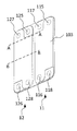
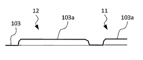
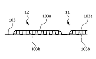
- FIG. 5 is a perspective view showing an example of the plate shown in FIG. 6 is a cross-sectional view of the plate shown in FIG. 5 along the line AA.
- 7 is a cross-sectional view of the plate shown in FIG. 5 taken along the line BB.
- one side (left side in FIG. 5) of the plate 103 is a region constituting the first heat exchanger 11, and the other side (right side in FIG. 5) constitutes the second heat exchanger 12. It becomes an area.
- a concave portion 103a is formed in each of the left and right regions of the plate 103.
- Inner fins 103b formed in a wavy shape are formed in regions other than the upper and lower ends of the concave portion 103a.
- openings 115 and 116 serving as coolant passages and openings 117 and 118 serving as coolant passages are formed on the first heat exchanger 11 side of the plate 103. Yes. Similarly, openings 125 and 126 serving as coolant passages and openings 127 and 128 serving as coolant passages are also formed on the second heat exchanger 12 side of the plate 103.
- an inlet 113 and an outlet 114 for the coolant flowing through the flow path of the first heat exchanger 11 are provided on the surface of one panel 101.
- an inlet 123 and an outlet 121 for the coolant flowing through the flow path of the second heat exchanger 12 are provided.
- a refrigerant inlet 111 and an outlet 112 are provided on the first heat exchanger 11 side of the other panel 102.
- a refrigerant outlet 122 is provided on the second heat exchanger 12 side.
- the panel 101 is provided with many parts such as the coolant inlets 113 and 123, the outlets 114 and 121, and the refrigerant inlet 124 on the surface thereof. It is relatively easy to ensure the strength.
- the receiver tank 13 that temporarily stores the refrigerant is integrally provided in the planar area of the panel 102 on the second heat exchanger 12 side. Specifically, the receiver tank 13 is fixed to a planar area of the panel 102. Thereby, since the wall surface of the panel 102 can be reinforced with the receiver tank 13, the intensity
- the receiver tank 13 has a role of maintaining an appropriate and stable operation of the heat pump cycle by temporarily storing the surplus refrigerant. For this reason, it is important for the receiver tank 13 to have an appropriate volume for stable heat pump operation.
- the receiver tank 13 is provided in a planar area on the second heat exchanger 12 side of the panel 102.
- the receiver tank 13 is provided on the second heat exchanger 12 side of the panel 102, but may be provided on the first heat exchanger 11 side. Moreover, it is good also as providing in the 1st heat exchanger 11 side and the 2nd heat exchanger 12 side of the panel 101.
- the receiver tank 13 is formed in a box shape having an opening on the panel 102 side, and a space for storing refrigerant is formed by the surface of the panel 102 and the receiver tank 13.
- the receiver tank 13 may be box-shaped, and the surface of the receiver tank 13 on the panel 102 side may be fixed to the surface of the panel 102.
- the receiver tank 13 is fixed to the panel 102 by brazing, for example.
- the receiver tank 13 and the panel 102 are formed from a metal such as an aluminum alloy, the receiver tank 13 and the panel 102 can be easily integrated by brazing.
- the receiver tank 13 with a rib (rib structure) that reaches the planar region of the panel 102 from the inner surface of the receiver tank 13, the strength of the region may be further increased.
- the heat exchange unit 100 of the present embodiment is also integrated with the receiver tank 13.
- the receiver tank 13 Is fixed to the planar area of the second heat exchanger 12, whereby the strength of the second heat exchanger 12 can be increased without adding a reinforcing member separately.
- coolant can be ensured easily, without receiving the restriction
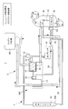
- FIG. 8 is a configuration diagram illustrating an example of a vehicle air conditioner according to an embodiment of the present disclosure.
- This vehicle air conditioner 1 is mounted on a vehicle equipped with an engine (internal combustion engine) 40, which is an example of a heat generating component of the vehicle, and is a device that adjusts air in the passenger compartment.
- the vehicle air conditioner 1 is disposed in an engine room.
- the vehicle air conditioner 1 includes a compressor 10, a heat exchange unit 100, an outdoor condenser 20, a heater core 31, an evaporator 32, an engine 40, a first on-off valve 51, a second on-off valve 52, expansion valves 53 and 54, and a check valve. 55.
- the vehicle air conditioner 1 includes a refrigerant pipe connecting the compressor 10, the outdoor capacitor 20, the expansion valve 54, and the evaporator 32, and a refrigerant pipe connecting the compressor 10 and the heat exchange unit 100.
- a refrigerant circuit 2 is provided.
- the vehicle air conditioner 1 includes a coolant circuit 3 including a coolant pipe connecting the heater core 31, the heat exchange unit 100, and the engine 40.
- the refrigerant pipe connecting the compressor 10 and the heat exchange unit 100 constitutes the heating refrigerant circuit 2 ⁇ / b> A, and connects the compressor 10, the outdoor capacitor 20, the expansion valve 54, and the evaporator 32.
- the piping forms a cooling refrigerant circuit 2B. Note that the refrigerant piping of the refrigerant circuit 2A for heating and the refrigerant circuit 2B for cooling is partially shared on the discharge port side of the compressor 10.
- the engine 40 includes an engine cooling unit.
- the engine cooling unit includes, for example, a water jacket for flowing a coolant around the engine 40 and a pump for flowing the coolant to the water jacket, and discharges exhaust heat from the engine 40 to the coolant flowing in the water jacket.
- the pump is rotated by the power of the engine 40, for example.
- the inlet of the coolant in the engine cooling part of the engine 40 is communicated with the first heat exchanger 11 of the heat exchange unit 100 via the coolant pipe. Further, the coolant outlet of the engine cooling section of the engine 40 is communicated with the second heat exchanger 12 of the heat exchange unit 100 via the coolant pipe.
- the engine cooling unit may be provided with a radiator that releases heat to the outside air when the amount of exhaust heat from the engine 40 increases.
- the cooling liquid is, for example, an antifreeze liquid such as LLC (Long Life Coolant), and is a liquid for transporting heat.
- an antifreeze liquid such as LLC (Long Life Coolant)
- the transfer of the coolant in the coolant circuit 3 can be performed using only the pump provided in the engine cooling unit. Thereby, reduction of the cost of an apparatus and reduction of the installation space of an apparatus can be aimed at.
- a pump may be added to another part of the coolant pipe.
- the compressor 10 is a device that is driven by engine power or electricity, compresses sucked refrigerant, and discharges high-temperature and high-pressure refrigerant.
- the refrigerant compressed by the compressor 10 is sent from the discharge port of the compressor 10 to the outdoor condenser 20 or the second heat exchanger 12 through the refrigerant pipe.
- the low-temperature and low-pressure refrigerant discharged from the first heat exchanger 11 or the evaporator 32 is sucked from the suction port of the compressor 10 through the refrigerant pipe.
- the refrigerant pipe extending from the discharge port of the compressor 10 is divided into a pipe that reaches the refrigerant inlet of the outdoor condenser 20 and a pipe that reaches the refrigerant inlet 124 (see FIG. 2) of the second heat exchanger 12.
- a branching portion for branching is provided.
- the refrigerant flows through the piping extending from the discharge port of the compressor 10 leading to this branching part both during heating and during cooling.
- a first on-off valve 51 capable of blocking the flow of the refrigerant is disposed in the pipe between the branch portion and the refrigerant inlet of the outdoor capacitor 20.
- a second open / close valve 52 capable of blocking the flow of the refrigerant is disposed in the pipe between the branch portion and the refrigerant inlet 124 of the second heat exchanger 12.
- the first on-off valve 51 and the second on-off valve 52 are valves that switch between opening and closing in the middle of the refrigerant pipe, for example, by electrical control.
- pilot valves that are a kind of electromagnetic valves are employed as the first on-off valve 51 and the second on-off valve 52.
- the high-temperature and high-pressure refrigerant discharged from the compressor 10 is sent to the cooling refrigerant circuit 2A including the outdoor capacitor 20, or Whether the refrigerant is sent to the heating refrigerant circuit 2B including the second heat exchanger 12 is selected.
- the second heat exchanger 12 functions as a sub-condenser during heating, exchanges heat between the high-temperature and high-pressure refrigerant and the coolant, and condenses the refrigerant.
- the refrigerant introduction port 124 of the second heat exchanger 12 is communicated with the discharge port of the compressor 10 through the refrigerant pipe of the heating refrigerant circuit 2A.
- the refrigerant outlet 122 of the second heat exchanger 12 communicates with the suction port of the compressor 10 through the expansion valve 53 and the first heat exchanger 11 in order through the refrigerant pipe of the refrigerant circuit 2A for heating. ing.
- the coolant inlet 123 of the second heat exchanger 12 communicates with the engine cooling part of the engine 40 through the coolant pipe.
- the coolant outlet 121 of the second heat exchanger 12 communicates with the heater core 31 via the coolant pipe.
- the first heat exchanger 11 functions as a sub-evaporator during heating, exchanges heat between the low-temperature and low-pressure refrigerant and the coolant, and evaporates the refrigerant.
- the refrigerant inlet 111 of the first heat exchanger 11 communicates with the expansion valve 53 via the refrigerant pipe of the refrigerant circuit 2A for heating.
- the refrigerant outlet 112 of the first heat exchanger 11 communicates with the inlet of the compressor 10 through the refrigerant pipe of the refrigerant circuit 2A for heating.
- the coolant inlet 113 of the first heat exchanger 11 communicates with the heater core 31 via the coolant pipe.
- the coolant outlet 121 of the second heat exchanger 12 communicates with the engine cooling section of the engine 40 via the coolant pipe.
- the expansion valve 53 expands the high-temperature and high-pressure refrigerant and discharges the low-temperature and low-pressure refrigerant to the first heat exchanger 11.
- the expansion valve 53 is disposed in the vicinity of the first heat exchanger 11 immediately upstream of the first heat exchanger 11.
- the expansion valve 53 is, for example, a temperature expansion valve (TXV) that has a function of automatically adjusting the refrigerant flow rate to be discharged according to the temperature of the refrigerant sent from the first heat exchanger 11.
- TXV temperature expansion valve
- the outdoor condenser 20 has a flow path for flowing a high-temperature and high-pressure refrigerant and a flow path for flowing air, and is disposed near the head of the vehicle in the engine room, for example, and performs heat exchange between the refrigerant and the outside air. .
- the high-temperature and high-pressure refrigerant discharged from the compressor 10 flows through the outdoor condenser 20 in the cooling mode described in detail later, and heat is discharged from the refrigerant to the outside air. Outside air is blown onto the outdoor capacitor 20 by, for example, a fan.
- a reservoir tank 20 a may be provided on the refrigerant delivery side of the outdoor capacitor 20.
- the heater core 31 and the evaporator 32 are disposed in an intake passage of an HVAC (Heating, “Ventilation,” and “Air” Conditioning) 30.
- the HVAC 30 is provided with a fan 34 for flowing intake air.
- the heater core 31 is included in the coolant circuit 3, and the evaporator 32 is included in the refrigerant circuit 2.
- the heater core 31 is a device that exchanges heat between the coolant and air, and is disposed in the intake passage of the HVAC 30 that supplies air into the passenger compartment. Heated coolant is supplied to the heater core 31 and releases heat to intake air (air sent to the vehicle interior) sent to the vehicle interior in the heating mode described in detail later.
- the heater core 31 can adjust the amount of air passing through the opening of the door 33 in the intake passage.
- the door 33 can be opened and closed by electrical control, and is also called a mix door.
- the evaporator 32 is a device that exchanges heat between the low-temperature and low-pressure refrigerant and the air, and is disposed in the intake passage of the HVAC 30. In the cooling mode, the evaporator 32 is supplied with a low-temperature and low-pressure refrigerant to cool the intake air (air sent to the vehicle compartment) supplied to the vehicle interior.
- the expansion valve 54 expands the high-pressure refrigerant and discharges the low-temperature and low-pressure refrigerant to the evaporator 32.
- the expansion valve 54 is disposed in the vicinity of the evaporator 32 immediately upstream of the evaporator 32.
- the expansion valve 54 is, for example, a temperature type expansion valve (TXV) having a function of automatically adjusting the refrigerant flow rate to be discharged according to the temperature of the refrigerant sent from the evaporator 32.
- TXV temperature type expansion valve
- a check valve 55 is arranged in the middle of the refrigerant circuit from the evaporator 32 to the compressor 10.
- the check valve 55 is a valve that prevents a reverse flow of the refrigerant in the heating mode in which the refrigerant does not flow to the outdoor condenser 20 and the evaporator 32.
- the refrigerant pressure in the outdoor condenser 20 and the evaporator 32 may be lowered.
- the refrigerant flowing in the refrigerant circuit 2A of the first heat exchanger 11 and the second heat exchanger 12 flows back to the cooling refrigerant circuit 2B on the evaporator 32 side, and the heat pump cycle Efficiency will decrease.
- Such inconvenience can be avoided by the presence of the check valve 55.
- the vehicle air conditioner 1 has a control system configuration in which a compressor 10 is driven, each operating part of the HVAC 30 is driven, the first on-off valve 51 and the second on-off valve 52 are opened and closed, and a pump that transfers cooling liquid by power. Etc. are provided with a control unit (not shown) for controlling the respective components.
- the control unit is, for example, a device including a microcomputer, an IO (Input / Output), a program memory storing a control program, a working memory, and the like, and the microcomputer performs predetermined control according to the control program. It may be configured as, or may be configured from a plurality of units.
- the operation modes of the vehicle air conditioner 1 include a hot water heating mode during heating, a heat pump heating mode, and a cooling mode during cooling.
- the vehicle air conditioner 1 switches between these operation modes.
- the hot water heating mode is a mode in which the passenger compartment is heated without operating the heat pump.
- the heat pump heating mode is a mode in which the vehicle interior is heated by operating the heat pump.
- the cooling mode is a mode in which the passenger compartment is cooled by the action of the heat pump.
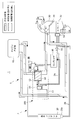
- FIG. 9 is a diagram for explaining the operation in the heat pump heating mode.
- This heating mode is a mode in which the first on-off valve 51 is closed and the second on-off valve 52 is opened. Further, the door 33 of the heater core 31 is opened (for example, fully opened).
- the refrigerant discharged from the compressor 10 passes through the second heat exchanger 12, the expansion valve 53, and the first heat exchanger 11 in order in the heating refrigerant circuit 2A, and returns to the compressor 10. Circulate like so.
- the refrigerant compressed by the compressor 10 dissipates heat to the coolant in the second heat exchanger 12 and condenses.
- the condensed refrigerant is expanded by the expansion valve 53 to become a low-temperature and low-pressure refrigerant, and is sent to the first heat exchanger 11.
- the low-temperature and low-pressure refrigerant absorbs heat from the coolant in the first heat exchanger 11 and evaporates.
- the evaporated low-pressure refrigerant is sucked into the compressor 10 and compressed again.
- the coolant circulates in the coolant circuit 3 so as to pass through the engine 40, the second heat exchanger 12, the heater core 31, and the first heat exchanger 11 in this order.
- the coolant that has absorbed the exhaust heat by the engine 40 is further heated by the second heat exchanger 12 and sent to the heater core 31.
- the coolant that has reached a high temperature can sufficiently heat the intake air that is sent into the passenger compartment by the heater core 31.
- the coolant that has passed through the heater core 31 has a higher temperature than the outside air, and the first heat exchanger 11 can release heat to the refrigerant to evaporate the refrigerant. Further, the coolant cooled by the first heat exchanger 11 is sent to the engine 40 and used for cooling the engine 40.
- Such operation in the heating mode can sufficiently heat the passenger compartment.
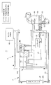
- FIG. 10 is a diagram for explaining the operation in the cooling mode.
- the cooling mode is a mode in which the first on-off valve 51 is opened and the second on-off valve 52 is closed. Further, the door 33 of the heater core 31 is fully closed.
- the refrigerant discharged from the compressor 10 circulates back to the compressor 10 through the outdoor condenser 20, the expansion valve 54, and the evaporator 32 in this order in the cooling refrigerant circuit 2B.
- the high-temperature and high-pressure refrigerant compressed by the compressor 10 dissipates heat to the air by the outdoor condenser 20 and condenses.
- the condensed refrigerant expands in the expansion valve 54 to become a low-temperature and low-pressure refrigerant and is sent to the evaporator 32.
- the low-temperature and low-pressure refrigerant is evaporated by the evaporator 32 by cooling the intake air sent to the passenger compartment.
- the evaporated low-pressure refrigerant is sucked into the compressor 10 and compressed.
- the flow of the coolant is the same as in the heating mode, and circulates in the coolant circuit 3 so as to pass through the engine 40, the second heat exchanger 12, the heater core 31, and the first heat exchanger 11 in order. To do.
- the coolant passes through the second heat exchanger 12, the heater core 31, and the first heat exchanger 11 in this order, it hardly exchanges heat with the refrigerant or air.
- the heat radiation of the coolant is mainly performed by a radiator of an engine cooling unit in the engine 40.
- the engine 40 Since the engine 40 is very hot, it is cooled by heat dissipation from the radiator even if the outside air temperature is high. Here, it is good also as employ
- the vehicle air conditioner 1 uses the configuration of the hot water heater that uses the coolant of the engine 40 to flow through the heater core 31 for heating and the low-temperature and low-pressure refrigerant of the heat pump. It also has a heat pump type cooling device that performs cooling as a basic configuration. And the heat exchange unit 100 is added to this basic structure, and it becomes the structure which can heat the vehicle interior using a heat pump. With such a configuration, even when the engine 40 is at a low temperature, the vehicle interior can be quickly heated with a small amount of energy by the action of the heat pump.
- the basic structure is the same as that of a hot water heater and a heat pump type cooling device as used in a conventional vehicle, and at the time of cooling and heating.
- the common compressor 10 and the refrigerant By using the common compressor 10 and the refrigerant, the heating performance can be improved at a low cost, and the increase in installation space can be reduced from the conventional configuration.
- the embodiments of the present disclosure have been described with reference to the drawings.
- the specific configuration is not limited to these embodiments, and the present disclosure may be modified or added without departing from the scope of the present disclosure.
- the heat exchange unit 100 of the present disclosure is not limited to the vehicle air conditioner 1 described in the embodiment, and can be used in various devices.
- the heat exchange unit 100 is 2nd heat.
- a configuration in which the exchanger 12 and the receiver tank 13 are integrated and the first heat exchanger 11 is provided separately may be employed.
- Such a heat exchange unit 100 can be applied to a hot gas cycle, for example.
- the present disclosure can be used for a vehicle air conditioner mounted on various vehicles such as an engine vehicle, an electric vehicle, or an HEV vehicle, and its heat exchange unit.
Landscapes
- Engineering & Computer Science (AREA)
- Physics & Mathematics (AREA)
- Thermal Sciences (AREA)
- Mechanical Engineering (AREA)
- General Engineering & Computer Science (AREA)
- Air-Conditioning For Vehicles (AREA)
- Details Of Heat-Exchange And Heat-Transfer (AREA)
Abstract
L'invention concerne une unité d'échangeur de chaleur comprenant : un échangeur de chaleur qui est configuré en intercalant de multiples plaques entre deux panneaux et qui effectue un échange de chaleur entre un liquide de refroidissement, pour refroidir un composant de génération de chaleur, et un fluide de refroidissement de climatisation d'air s'écoulant entre les plaques ; et un réservoir qui stocke le fluide de refroidissement. L'échangeur de chaleur et le réservoir sont intégrés l'un à l'autre, et le réservoir est fixé dans une région d'une surface de l'un ou l'autre des deux panneaux.
Applications Claiming Priority (2)
| Application Number | Priority Date | Filing Date | Title |
|---|---|---|---|
| JP2016-062671 | 2016-03-25 | ||
| JP2016062671A JP2017172948A (ja) | 2016-03-25 | 2016-03-25 | 熱交換ユニットおよび車両用空調装置 |
Publications (1)
| Publication Number | Publication Date |
|---|---|
| WO2017163563A1 true WO2017163563A1 (fr) | 2017-09-28 |
Family
ID=59901049
Family Applications (1)
| Application Number | Title | Priority Date | Filing Date |
|---|---|---|---|
| PCT/JP2017/001642 Ceased WO2017163563A1 (fr) | 2016-03-25 | 2017-01-19 | Unité d'échangeur de chaleur et dispositif de climatisation d'air pour véhicule |
Country Status (2)
| Country | Link |
|---|---|
| JP (1) | JP2017172948A (fr) |
| WO (1) | WO2017163563A1 (fr) |
Families Citing this family (3)
| Publication number | Priority date | Publication date | Assignee | Title |
|---|---|---|---|---|
| KR20230108064A (ko) * | 2022-01-10 | 2023-07-18 | 한온시스템 주식회사 | 매니폴드 냉매 모듈 |
| KR20240018078A (ko) * | 2022-08-02 | 2024-02-13 | 한온시스템 주식회사 | 매니폴드 유체 모듈 |
| KR20240174334A (ko) * | 2023-06-08 | 2024-12-17 | 한온시스템 주식회사 | 차량용 열관리 유체 모듈 |
Citations (7)
| Publication number | Priority date | Publication date | Assignee | Title |
|---|---|---|---|---|
| JPH11287572A (ja) * | 1998-03-31 | 1999-10-19 | Hisaka Works Ltd | ブレージングプレート式熱交換器 |
| JP2012127551A (ja) * | 2010-12-14 | 2012-07-05 | Corona Corp | ヒートポンプ装置 |
| EP2476975A2 (fr) * | 2011-01-12 | 2012-07-18 | Behr GmbH & Co. KG | Dispositif de transfert thermique pour un véhicule |
| US20120216562A1 (en) * | 2011-02-17 | 2012-08-30 | Delphi Technologies, Inc. | Unitary heat pump air conditioner having a heat exchanger with an integral accumulator |
| WO2014119272A1 (fr) * | 2013-01-30 | 2014-08-07 | 株式会社デンソー | Réservoir de liquide et échangeur de chaleur avec réservoir de liquide intégré |
| WO2015011887A1 (fr) * | 2013-07-25 | 2015-01-29 | パナソニックIpマネジメント株式会社 | Dispositif de climatisation pour véhicule et unité constitutive de celui-ci |
| JP2016001099A (ja) * | 2014-05-23 | 2016-01-07 | 株式会社デンソー | 積層型熱交換器 |
-
2016
- 2016-03-25 JP JP2016062671A patent/JP2017172948A/ja active Pending
-
2017
- 2017-01-19 WO PCT/JP2017/001642 patent/WO2017163563A1/fr not_active Ceased
Patent Citations (7)
| Publication number | Priority date | Publication date | Assignee | Title |
|---|---|---|---|---|
| JPH11287572A (ja) * | 1998-03-31 | 1999-10-19 | Hisaka Works Ltd | ブレージングプレート式熱交換器 |
| JP2012127551A (ja) * | 2010-12-14 | 2012-07-05 | Corona Corp | ヒートポンプ装置 |
| EP2476975A2 (fr) * | 2011-01-12 | 2012-07-18 | Behr GmbH & Co. KG | Dispositif de transfert thermique pour un véhicule |
| US20120216562A1 (en) * | 2011-02-17 | 2012-08-30 | Delphi Technologies, Inc. | Unitary heat pump air conditioner having a heat exchanger with an integral accumulator |
| WO2014119272A1 (fr) * | 2013-01-30 | 2014-08-07 | 株式会社デンソー | Réservoir de liquide et échangeur de chaleur avec réservoir de liquide intégré |
| WO2015011887A1 (fr) * | 2013-07-25 | 2015-01-29 | パナソニックIpマネジメント株式会社 | Dispositif de climatisation pour véhicule et unité constitutive de celui-ci |
| JP2016001099A (ja) * | 2014-05-23 | 2016-01-07 | 株式会社デンソー | 積層型熱交換器 |
Also Published As
| Publication number | Publication date |
|---|---|
| JP2017172948A (ja) | 2017-09-28 |
Similar Documents
| Publication | Publication Date | Title |
|---|---|---|
| CN105431313B (zh) | 车辆用空调装置 | |
| US12109869B2 (en) | Temperature adjusting device | |
| CN105408142B (zh) | 车辆用空调装置 | |
| JP6304578B2 (ja) | 車両用空調装置 | |
| JP5866699B2 (ja) | 車両用空調装置およびその構成ユニット | |
| JP6590321B2 (ja) | 車両用空調装置 | |
| WO2016059791A1 (fr) | Dispositif de climatisation pour véhicule | |
| KR20210079741A (ko) | 차량용 냉난방 시스템 | |
| CN118922674A (zh) | 复合型热交换器、热交换系统 | |
| WO2021261320A1 (fr) | Dispositif de refroidissement de véhicule | |
| WO2015008463A1 (fr) | Climatiseur de véhicule et son unité constituante | |
| WO2017163563A1 (fr) | Unité d'échangeur de chaleur et dispositif de climatisation d'air pour véhicule | |
| JP2017081560A (ja) | 車両用空調装置の構成ユニット | |
| JP2017040421A (ja) | 熱交換器及びヒートポンプシステム | |
| WO2020246306A1 (fr) | Dispositif de climatisation de véhicule | |
| CN115742660A (zh) | 车辆热管理系统 | |
| CN120056697B (zh) | 一种基于r290制冷剂的汽车热管理系统 | |
| WO2020241612A1 (fr) | Dispositif de climatisation de véhicule | |
| WO2020246305A1 (fr) | Dispositif de climatisation de véhicule | |
| CN118274488B (zh) | 热管理系统以及车辆 | |
| KR102830845B1 (ko) | 차량용 냉난방 시스템 | |
| JP2017171248A (ja) | 車両用空調装置 | |
| CN110375463B (zh) | 低温热泵系统 | |
| JP2018177096A (ja) | 車両用空調装置 |
Legal Events
| Date | Code | Title | Description |
|---|---|---|---|
| NENP | Non-entry into the national phase |
Ref country code: DE |
|
| 121 | Ep: the epo has been informed by wipo that ep was designated in this application |
Ref document number: 17769610 Country of ref document: EP Kind code of ref document: A1 |
|
| 122 | Ep: pct application non-entry in european phase |
Ref document number: 17769610 Country of ref document: EP Kind code of ref document: A1 |