WO2017163622A1 - Système de distribution d'endoprothèses vasculaires - Google Patents
Système de distribution d'endoprothèses vasculaires Download PDFInfo
- Publication number
- WO2017163622A1 WO2017163622A1 PCT/JP2017/003808 JP2017003808W WO2017163622A1 WO 2017163622 A1 WO2017163622 A1 WO 2017163622A1 JP 2017003808 W JP2017003808 W JP 2017003808W WO 2017163622 A1 WO2017163622 A1 WO 2017163622A1
- Authority
- WO
- WIPO (PCT)
- Prior art keywords
- delivery system
- state
- stent
- stent delivery
- tube
- Prior art date
- Legal status (The legal status is an assumption and is not a legal conclusion. Google has not performed a legal analysis and makes no representation as to the accuracy of the status listed.)
- Ceased
Links
Images




Classifications
-
- A—HUMAN NECESSITIES
- A61—MEDICAL OR VETERINARY SCIENCE; HYGIENE
- A61F—FILTERS IMPLANTABLE INTO BLOOD VESSELS; PROSTHESES; DEVICES PROVIDING PATENCY TO, OR PREVENTING COLLAPSING OF, TUBULAR STRUCTURES OF THE BODY, e.g. STENTS; ORTHOPAEDIC, NURSING OR CONTRACEPTIVE DEVICES; FOMENTATION; TREATMENT OR PROTECTION OF EYES OR EARS; BANDAGES, DRESSINGS OR ABSORBENT PADS; FIRST-AID KITS
- A61F2/00—Filters implantable into blood vessels; Prostheses, i.e. artificial substitutes or replacements for parts of the body; Appliances for connecting them with the body; Devices providing patency to, or preventing collapsing of, tubular structures of the body, e.g. stents
- A61F2/95—Instruments specially adapted for placement or removal of stents or stent-grafts
- A61F2/962—Instruments specially adapted for placement or removal of stents or stent-grafts having an outer sleeve
- A61F2/966—Instruments specially adapted for placement or removal of stents or stent-grafts having an outer sleeve with relative longitudinal movement between outer sleeve and prosthesis, e.g. using a push rod
Definitions
- the present invention relates to a stent delivery system.
- a cylindrical stent is placed in the blood vessel to widen the stenosis (occlusion), which is the target site, and a treatment method for ensuring blood flow is known. It has been.
- a stent delivery system is used in which a stent is delivered to a target site and placed (for example, see Patent Document 1).
- the stent delivery system described in Patent Document 1 includes a catheter having a stent accommodating portion that accommodates a stent at a distal end portion, and is used with a guide wire into which the catheter can be inserted.
- the outer diameter of the stent housing portion is designed according to the size of the stent. Therefore, a step may occur between the outer diameter of the stent housing portion located on the distal end side of the catheter and the outer diameter of the shaft located on the proximal side of the catheter.
- the step formed between the distal end portion and the proximal end portion of the catheter deteriorates the blood vessel penetrability of the catheter or unintentionally forms the stent from the stent accommodating portion. There is a concern that it may be detached, and there is a concern that the procedure efficiency is lowered.
- An object of the present invention is to provide a stent delivery system capable of improving blood vessel penetration and easily performing an operation for removing a stent.
- a stent delivery system comprising an outer tube and an inner tube that is inserted into the outer tube and has a storage portion that stores a stent at a distal end portion, The storage portion protrudes from the outer tube in a state in which the stent is stored, and has a first state in which the diameter is larger than an inner diameter of the outer tube, and is folded and contracted in a state in which the stent is detached. Take the second state that entered the tube, The stent delivery system is provided with a start portion for starting folding of the storage portion when the storage portion is folded in the process of shifting from the first state to the second state. .
- a thickness of a tube wall in the storage portion of the inner tube is 0.01 mm or more and 1 mm or less.
- the auxiliary portion is provided in the outer tube, and at least one of cutting the storage portion along the longitudinal direction of the inner tube in the process of shifting from the first state to the second state.
- the stent delivery system according to the above (6) having a blade portion.
- the stent can be transported in a state where the storage portion of the inner tube is in the first state and the storage portion and the distal end opening of the outer tube are brought close to each other.
- the stent delivery system can suppress the outer diameter difference between the inner tube and the outer tube on the distal end side of the double tube structure, the stent delivery system is excellent in blood vessel penetration.
- the inner tube is pulled toward the proximal direction with respect to the outer tube.
- the storage portion can start folding at the start portion, and can start the detachment of the stent from the distal end opening of the storage portion.
- the storage portion is folded into a second state with a reduced diameter and inserted into the outer tube, and the distal end of the storage portion
- the stent can be completely removed from the opening.
- the stent delivery system is excellent in blood vessel penetration, and can reliably and easily remove the stent.
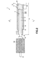
- FIG. 1 is a partial longitudinal sectional view showing a use state in the first embodiment of the stent delivery system of the present invention.
- FIG. 2 is a partial longitudinal sectional view showing a use state in the first embodiment of the stent delivery system of the present invention.
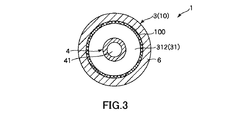
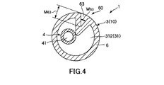
- 3 is a cross-sectional view taken along line AA in FIG. 4 is a cross-sectional view taken along line BB in FIG.
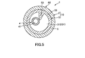
- FIG. 5 is a cross-sectional view taken along the line CC in FIG.
- FIG. 6 is a cross-sectional view of the storage portion of the inner tube in the second embodiment of the stent delivery system of the present invention.
- FIG. 7 is a cross-sectional view of a storage portion of an inner tube in a third embodiment of the stent delivery system of the present invention.
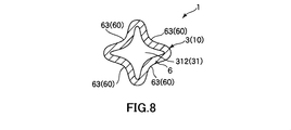
- FIG. 8 is a cross-sectional view of the storage portion of the inner tube in the fourth embodiment of the stent delivery system of the present invention.
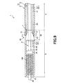
- FIG. 9 is a partial longitudinal sectional view showing a fifth embodiment of the stent delivery system of the present invention.
- FIG. 10 is a cross-sectional perspective view of the storage portion of the inner tube in the stent delivery system shown in FIG.
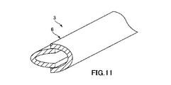
- FIG. 11 is a cross-sectional perspective view of the storage portion of the inner tube in the stent delivery system shown in FIG.
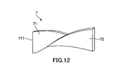
- FIG. 12 is a perspective view showing an auxiliary portion that assists folding in the storage portion in the sixth embodiment of the stent delivery system of the present invention.
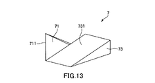
- FIG. 13 is a perspective view which shows the auxiliary
- FIG. 1 and FIG. 2 are partial longitudinal sectional views each showing a use state in the first embodiment of the stent delivery system of the present invention.
- 3 is a cross-sectional view taken along line AA in FIG. 4 is a cross-sectional view taken along line BB in FIG.
- FIG. 5 is a cross-sectional view taken along the line CC in FIG.
- the right side in FIGS. 1 and 2 (the same applies to FIG. 9) is referred to as “base end”, and the left side is referred to as “tip”.
- the radial direction of the stent delivery system is schematically exaggerated for easy understanding, and the ratio between the longitudinal direction and the radial direction is actually shown. Is different.
- the stent delivery system 1 shown in FIGS. 1 and 2 is a medical device that places a stent 100 in a blood vessel.
- This stent delivery system 1 includes a double tube structure 10 having a double tube structure having an outer tube 2 and an inner tube 3, and an operation tube 4 as an operation unit for performing an operation of releasing the stent 100. I have.
- the stent 100 When a lesion such as a stenosis or occlusion occurs on the blood vessel wall, the stent 100 can be placed in the blood vessel to expand the lesion as a target site from the inside. Thereby, the blood flow in the blood vessel is ensured.
- the stent 100 is configured such that a large number of linear bodies are combined in a braided shape, and the overall shape forms a cylindrical shape.
- the constituent material of the stent 100 is not particularly limited.
- a superelastic alloy such as a Ni—Ti alloy that exhibits superelasticity in the living body at about 37 ° C. can be used.
- the stent 100 can be contracted in the stent delivery system 1, and when the stent 100 is detached from the stent delivery system 1, the stent 100 expands to return to the original shape by the elastic force of the stent 100 itself, thereby It can be reliably spread from.
- the stent delivery system 1 is used to arrange such a stent 100 in the blood vessel.
- the stent delivery system 1 includes the outer tube 2, the inner tube 3, and the operation tube 4.
- the configuration of each unit will be described.
- the outer tube 2 is a flexible tube having a lumen 21.
- the outer diameter ⁇ d 2-1 of the outer tube 2 depends on the blood vessel in which the stent delivery system 1 is used, but is preferably 0.6 mm or more and 6.0 mm or less, preferably 0.6 mm or more, and 2. More preferably, it is 4 mm or less.
- the inner tube 3 is inserted into the outer tube 2.
- the inner tube 3 is a flexible tube having a lumen 31 and can be moved along the longitudinal direction with respect to the outer tube 2.
- the inner tube 3 includes a long main body portion 5 and a storage portion 6 that is provided at a distal end portion on the distal end side of the main body portion 5 and stores the stent 100.
- the lumen 31 can be divided into a first lumen 311 located on the main body part 5 side and a second lumen 312 located on the storage part 6 side.
- the second lumen 312 functions as a space for storing the stent 100 in a contracted state.
- the main body 5 occupies most of the inner tube 3, and the outer diameter ⁇ d 5 is constant along the longitudinal direction of the inner tube 3. This outer diameter ⁇ d 5 is smaller than the inner diameter ⁇ d 2-2 of the outer tube 2.
- the storage unit 6 takes the first state shown in FIG. 1 and the second state shown in FIG.
- the first state is a state in which the storage portion 6 in the state where the stent 100 is stored protrudes from the distal end opening portion 22 of the outer tube 2 and the distal end opening portion 22 and the proximal end portion of the storage portion 6 are held close to each other. is there.
- the first state is a state in which the outer diameter ⁇ d 6 of the storage portion 6 is larger than the inner diameter ⁇ d 2-2 of the outer tube 2.
- the accommodating part 6 will be in a 2nd state by moving the inner pipe
- the second state is a state in which the storage portion 6 in a state in which the stent 100 is detached is folded and reduced in diameter, and enters the outer tube 2.
- the stent 100 will detach
- the inner tube 3 may be one in which the main body portion 5 and the storage portion 6 are integrally formed, or the main body portion 5 and the storage portion 6 are configured as separate bodies, and these separate bodies are separated from each other. It may be joined.
- the constituent materials of the respective parts can be varied depending on the purpose, for example.
- an operation tube 4 is inserted into the inner tube 3.
- the operating tube 4 is a flexible tube having a lumen 41.
- a guide wire (not shown) can be inserted into the lumen 41. Then, the stent delivery system 1 can be pushed forward along the guide wire while the guide wire is advanced in a state where the distal end portion of the guide wire is protruded from the distal end opening 42 of the operation tube 4.
- the operation tube 4 has a long main body 43 and a diameter-expanded portion 44 that is provided in the middle of the main body 43 in the longitudinal direction and whose outer diameter is increased.
- the enlarged diameter portion 44 moves the stent 100 accommodated in the accommodating portion 6 to the proximal end side in the longitudinal direction of the operating tube 4 in the process of the accommodating portion 6 shifting from the first state to the second state. Do not fix. Further, only the inner tube 3 moves to the proximal end side with respect to the operation tube 4 in the process in which the storage portion 6 shifts from the first state to the second state. Therefore, the stent 100 fixed in position by the enlarged-diameter portion 44 of the operation tube 4 is in the same position on the operation tube 4 in the process in which the storage unit 6 shifts from the first state to the second state. Retained.
- the operation tube body 4 may be one in which the main body portion 43 and the enlarged diameter portion 44 are integrally formed, or the main body portion 43 and the enlarged diameter portion 44 are configured separately. What joined another body may be sufficient.
- the constituent materials of the respective portions can be varied depending on the purpose, for example.
- the constituent materials of the outer tube 2, the inner tube 3, and the operation tube 4 are not particularly limited.
- polyolefin such as polypropylene, polyethylene, ethylene-vinyl acetate copolymer, polyamide, polyethylene terephthalate, polybutylene terephthalate, etc.
- Polyester polyurethane, polyvinyl chloride, polystyrene resin, fluororesin such as ethylene-tetrafluoroethylene copolymer, various flexible resins such as polyimide, polyamide elastomer, polyester elastomer, polyurethane elastomer, polystyrene elastomer, Various elastomers such as fluorine-based elastomers, silicone rubbers, latex rubbers, or combinations of two or more thereof can be used.
- the constituent material of the outer tube 2, the constituent material of the inner tube 3, and the constituent material of the operation tube 4 may be the same or different.
- the outer diameter .phi.d 6 of the housing part 6 has a larger diameter than the inner diameter .phi.d 2-2 of the outer tube 2. For this reason, the storage part 6 cannot enter the outer tube 2 as it is. Therefore, the storage unit 6 is configured to be in a second state in which the storage unit 6 is folded and reduced in diameter.
- this configuration will be described.
- a starting part 60 is provided as a trigger.
- the start portion 60 includes a tapered portion 62 provided at the proximal end portion of the outer peripheral portion of the storage portion 6 and a single groove 63 provided at the outer peripheral portion of the storage portion 6.
- the tapered portion 62, the outer diameter .phi.d 6 is progressively reduced toward the proximal end. As shown in FIGS. 1 and 2, the tapered portion 62 is a portion that mainly contributes to the folding of the storage portion 6 in the radial direction.
- the total length L 62 of the tapered portion 62 is not particularly limited, for example, 0.1% or more of the total length L 6 of the housing part 6, but preferably not more than 100%, 0.1% or more, 10% or less It is more preferable that
- the taper angle ⁇ 62 of the taper portion 62 in the first state is not particularly limited, and is preferably 1 ° or more and 179 ° or less, and more preferably 10 ° or more and 120 ° or less. preferable.
- the groove 63 is formed along the longitudinal direction of the inner tube 3.
- the groove 63 is formed by making a crease in the storage portion 6.
- the groove 63 is a portion that mainly contributes to the folding of the storage portion 6 in the circumferential direction.
- channel 63 may cover the full length of the accommodating part 6, it is preferable to set it as the range into which the accommodating part 6 is inserted in the outer tube 2 at least by the 2nd state.
- the width w 63 of the groove 63 is gradually reduced toward the center of the storage portion 6 in the present embodiment, and the maximum is preferably, for example, more than 0 mm and 1 mm or less in the first state.
- the width w 63 may be constant along the longitudinal direction of the inner tube 3 or may vary.
- the maximum depth M 63 of the groove 63 is not particularly limited, for example, 0.2 mm or more, preferably at 2mm or less, 0.2 mm or more, more preferably 1mm or less.
- the storage unit 6 By providing the storage unit 6 with the start unit 60 having the above-described configuration, first, as illustrated in FIG. 1, the storage unit 6 is set to the first state until the stent 100 is indwelled. In this state, the proximal end portion 6 and the distal end opening 22 of the outer tube 2 are brought close to each other, and can be transported to a target site in the blood vessel. For this reason, the length in which the main body 5 of the inner tube 3 protrudes from the distal end opening 22 between the distal end opening 22 of the outer tube 2 and the housing 6 of the inner tube 3 can be minimized.
- the stent delivery system 1 has the outer diameter on the distal end side of the double-pipe structure portion 10 due to the difference in outer diameters of the storage portion 6, the main body portion 5 and the outer tube 2 on the distal end side of the double-pipe structure portion 10. Changes can be minimized, and intravascular penetration can be improved.
- the inner tube 3 is pulled toward the proximal direction with respect to the outer tube 2.
- the inner tube 3 moves to the proximal end side with respect to the outer tube 2 and the operation tube 4.
- the tapered portion 62 of the storage portion 6 is pressed in the direction in which the outer diameter ⁇ d 6 is reduced by the inner peripheral portion 23 of the outer tube 2 as shown in FIG.
- the width w 63 is pressed in the decreasing direction. That is, the storage unit 6 starts to be folded at the start unit 60 and starts to be detached from the distal end opening 61 of the storage unit 6.
- the storage portion 6 is inserted into the outer tube 2 in a second state that is folded and reduced in diameter.
- the stent 100 is completely detached from the six distal end openings 61.
- the stent 100 detached from the storage portion 6 can be expanded by its own elastic force, and the lesion can be reliably expanded.
- the stent delivery system 1 improves the blood vessel penetrability and reliably and easily removes the stent.
- FIG. 6 is a cross-sectional view of the storage portion of the inner tube in the second embodiment of the stent delivery system of the present invention.
- This embodiment is the same as the first embodiment except that the number of grooves forming the start portion is different.
- two grooves 63 constituting the start portion 60 are provided. These two grooves 63 are arranged at equal intervals along the circumferential direction of the outer peripheral portion of the storage portion 6, that is, at positions facing each other via the central axis of the storage portion 6.
- FIG. 7 is a cross-sectional view of a storage portion of an inner tube in a third embodiment of the stent delivery system of the present invention.
- This embodiment is the same as the second embodiment except that the number of grooves forming the start portion is different.
- three grooves 63 constituting the start portion 60 are provided. These three grooves 63 are arranged at equal intervals along the circumferential direction of the outer peripheral portion of the storage portion 6.
- the folding is more than in the case of the second embodiment. It will be started more easily and quickly.
- the storage part 6 is smoothly contracted in the circumferential direction.
- these grooves 63 may be a width w 63 are the same or different.
- the maximum depth M 63 also may be the same or may be different.
- FIG. 8 is a cross-sectional view of the storage portion of the inner tube in the fourth embodiment of the stent delivery system of the present invention.
- This embodiment is the same as the third embodiment except that the number of grooves forming the start portion is different.
- each groove 63 constituting the start portion 60 is provided. These four grooves 63 are arranged at equal intervals along the circumferential direction of the outer peripheral portion of the storage portion 6.
- FIG. 9 is a partial longitudinal sectional view showing a fifth embodiment of the stent delivery system of the present invention.
- FIGS. 10 and 11 are perspective cross-sectional views of a storage portion of the inner tube in the stent delivery system shown in FIG.
- This embodiment is the same as the first embodiment except that an auxiliary part that assists folding in the storage part is provided.
- the stent delivery system 1 further includes an auxiliary portion 7 that assists folding in the storage portion 6.
- the auxiliary portion 7 is composed of two blade portions 71 provided on the distal end side of the inner peripheral portion 23 of the outer tube 2.
- These two blade portions 71 are arranged at equal intervals along the inner peripheral portion 23 of the outer tube 2, that is, in a direction facing each other via the central axis of the outer tube 2. Moreover, the blade surface 711 of each blade part 71 faces the front end side. Thereby, the accommodating part 6 is cut
- the storage unit 6 is cut by the blade unit 71 to be at least two cut pieces. And in the outer tube 2, these cut pieces are accommodated by overlapping each other in the radial direction.
- these overlapping modes for example, depending on various conditions such as the use state of the stent delivery system 1, it is shown in FIG. There are a mode and a mode shown in FIG.
- the overlapping state of the cut pieces shown in FIGS. 10 and 11 can be suitably adjusted.
- channel 63 is formed is preferable.
- the blade part 71 may be spaced apart from the storage part 6 in the first state in advance, it is preferable that the blade part 71 is inserted into the storage part 6 in advance as shown in FIG. Thereby, the accommodating part 6 can be cut
- the number of blades 71 installed is two in the present embodiment, but is not limited thereto, and may be one or three or more, for example.
- FIG. 12 is a perspective view showing an auxiliary portion that assists folding in the storage portion in the sixth embodiment of the stent delivery system of the present invention.
- assistant part 7 has the forced deformation part 72 which forcibly deforms the cut piece cut
- the forced deformation portion 72 is a portion formed so as to continuously extend from the blade surface 711 of the blade portion 71 toward the proximal end side of the outer tube 2 along the longitudinal direction of the outer tube 2.
- the forced deformation portion 72 is formed by being twisted and deformed with respect to the blade portion 71. Thereby, the cut piece of the storage portion 6 is twisted along the shape of the forced deformation portion 72 in the outer tube 2. Therefore, the cut pieces of the storage portion 6 are easily overlapped with each other as shown in FIGS. 10 and 11, and the folding can be further promoted.
- FIG. 13 is a perspective view which shows the auxiliary
- the seventh embodiment of the stent delivery system of the present invention will be described with reference to this figure, but the description will focus on differences from the above-described embodiment, and the description of the same matters will be omitted.
- This embodiment is the same as the sixth embodiment except that the shape of the forced deformation portion is different.
- the forced deformation portion 73 has an inclined surface 731 that is inclined with respect to the central axis direction of the outer tube 2.
- the cut pieces of the storage unit 6 ride on the inclined surface 731 in the outer tube 2 and are deformed. Therefore, the cut pieces of the storage unit 6 easily overlap each other as shown in FIGS. 10 and 11. Thus, folding can be further promoted.
- each part which comprises a stent delivery system is arbitrary structures which can exhibit the same function. Can be substituted. Moreover, arbitrary components may be added.
- the stent delivery system of the present invention may be a combination of any two or more configurations and features of the above embodiments.
- the number of grooves forming the start portion is one in the first embodiment, two in the second embodiment, three in the third embodiment, and four in the fourth embodiment. However, it is not limited to these, For example, 5 or more may be sufficient.
- auxiliary portion that assists folding in the storage portion is the blade portion in the fifth embodiment, but is not limited thereto, and may be, for example, a rubber band that applies an external compressive force.
- the stent delivery system of the present invention is a stent delivery system comprising an outer tube and an inner tube inserted into the outer tube and having a storage portion for storing the stent at a distal end portion, and the storage portion includes the stent.
- the storage portion is provided with a start portion for starting the folding of the storage portion when the storage portion is folded in the process of shifting from the first state to the second state. Therefore, it is possible to easily perform the operation of improving the blood vessel penetrability and removing the stent. Therefore, the stent delivery system of the present invention has industrial applicability.
Landscapes
- Health & Medical Sciences (AREA)
- Engineering & Computer Science (AREA)
- Biomedical Technology (AREA)
- Cardiology (AREA)
- Oral & Maxillofacial Surgery (AREA)
- Transplantation (AREA)
- Heart & Thoracic Surgery (AREA)
- Vascular Medicine (AREA)
- Life Sciences & Earth Sciences (AREA)
- Animal Behavior & Ethology (AREA)
- General Health & Medical Sciences (AREA)
- Public Health (AREA)
- Veterinary Medicine (AREA)
- Media Introduction/Drainage Providing Device (AREA)
Abstract
La présente invention concerne un système de distribution d'endoprothèses vasculaires qui est un instrument médical comportant un tube extérieur, et un tube intérieur qui est inséré dans le tube extérieur et dont l'extrémité avant comprend une section de logement pour le logement d'une endoprothèse vasculaire. La section de logement de ce système de distribution d'endoprothèses vasculaires prend un premier état de saillie depuis le tube extérieur lorsque l'endoprothèse vasculaire est logée dans la section de logement et d'élargissement du diamètre de sorte que le diamètre soit supérieur au diamètre intérieur du tube extérieur, et un deuxième état de désolidarisation de l'endoprothèse vasculaire, de pliage, de réduction de diamètre, et de fermeture dans le tube extérieur. En outre, la section de logement comporte une partie de déclenchement dans laquelle est déclenché le pliage de la section de logement, lorsque la section de logement doit être pliée pour la transition du premier état au deuxième état.
Applications Claiming Priority (2)
| Application Number | Priority Date | Filing Date | Title |
|---|---|---|---|
| JP2016-059162 | 2016-03-23 | ||
| JP2016059162 | 2016-03-23 |
Publications (1)
| Publication Number | Publication Date |
|---|---|
| WO2017163622A1 true WO2017163622A1 (fr) | 2017-09-28 |
Family
ID=59901137
Family Applications (1)
| Application Number | Title | Priority Date | Filing Date |
|---|---|---|---|
| PCT/JP2017/003808 Ceased WO2017163622A1 (fr) | 2016-03-23 | 2017-02-02 | Système de distribution d'endoprothèses vasculaires |
Country Status (1)
| Country | Link |
|---|---|
| WO (1) | WO2017163622A1 (fr) |
Citations (3)
| Publication number | Priority date | Publication date | Assignee | Title |
|---|---|---|---|---|
| JP2012075935A (ja) * | 2005-08-30 | 2012-04-19 | Gore Enterprise Holdings Inc | 拡張可能なデバイス用の展開システム |
| JP2013512705A (ja) * | 2009-12-03 | 2013-04-18 | アンジオメト・ゲーエムベーハー・ウント・コンパニー・メディツィンテクニク・カーゲー | ステント装置移送システムおよびその製造方法 |
| JP2014525810A (ja) * | 2011-08-12 | 2014-10-02 | ダブリュ.エル.ゴア アンド アソシエイツ,インコーポレイティド | 外転可能シース装置、システム、および、方法 |
-
2017
- 2017-02-02 WO PCT/JP2017/003808 patent/WO2017163622A1/fr not_active Ceased
Patent Citations (3)
| Publication number | Priority date | Publication date | Assignee | Title |
|---|---|---|---|---|
| JP2012075935A (ja) * | 2005-08-30 | 2012-04-19 | Gore Enterprise Holdings Inc | 拡張可能なデバイス用の展開システム |
| JP2013512705A (ja) * | 2009-12-03 | 2013-04-18 | アンジオメト・ゲーエムベーハー・ウント・コンパニー・メディツィンテクニク・カーゲー | ステント装置移送システムおよびその製造方法 |
| JP2014525810A (ja) * | 2011-08-12 | 2014-10-02 | ダブリュ.エル.ゴア アンド アソシエイツ,インコーポレイティド | 外転可能シース装置、システム、および、方法 |
Similar Documents
| Publication | Publication Date | Title |
|---|---|---|
| JP6274233B2 (ja) | クリップカートリッジシステム | |
| US20200093508A1 (en) | Intravascular catheter having an expandable incising portion | |
| JP6391910B2 (ja) | 吸引カテーテル | |
| JP5961603B2 (ja) | 固定デバイス及びカテーテルセット | |
| JP2008173463A (ja) | 留置針組立体 | |
| JP6752816B2 (ja) | 接続具、医療用クリップ装置および医療用クリップ装置の製造方法 | |
| JP2019503787A (ja) | 医用デバイスおよび関連する使用方法 | |
| JP2015002920A (ja) | ガイドワイヤ挿入装置 | |
| JPWO2020059122A1 (ja) | ダイレータ | |
| JP6581513B2 (ja) | 医療用長尺体 | |
| JP4778956B2 (ja) | ダブルバルーンカテーテル | |
| JP5954622B2 (ja) | ケース付きカテーテルおよびカテーテル収容用ケース | |
| KR102165477B1 (ko) | 내시경용 주사 바늘 | |
| JP7411640B2 (ja) | カテーテル | |
| JP6101681B2 (ja) | バルーンカテーテルおよびステントデリバリーシステム | |
| WO2017163622A1 (fr) | Système de distribution d'endoprothèses vasculaires | |
| JP2009189386A (ja) | カテーテルへのガイドワイヤー導入補助具 | |
| US20220080163A1 (en) | Balloon catheter | |
| KR20230123469A (ko) | 벌룬 카테터용 벌룬 | |
| JP4495501B2 (ja) | 内視鏡用突没型処置具 | |
| JP2017093874A (ja) | バルーンカテーテルおよびバルーン | |
| CN119300879A (zh) | 用于抽吸导管的导引器工具 | |
| JP2019170521A (ja) | 医療用バスケット型処置器具 | |
| JP7279466B2 (ja) | カテーテル | |
| JP2016030033A (ja) | ステントデリバリーカテーテル |
Legal Events
| Date | Code | Title | Description |
|---|---|---|---|
| NENP | Non-entry into the national phase |
Ref country code: DE |
|
| 121 | Ep: the epo has been informed by wipo that ep was designated in this application |
Ref document number: 17769669 Country of ref document: EP Kind code of ref document: A1 |
|
| 122 | Ep: pct application non-entry in european phase |
Ref document number: 17769669 Country of ref document: EP Kind code of ref document: A1 |
|
| NENP | Non-entry into the national phase |
Ref country code: JP |