WO2017164166A1 - 鞍乗型車両 - Google Patents
鞍乗型車両 Download PDFInfo
- Publication number
- WO2017164166A1 WO2017164166A1 PCT/JP2017/011200 JP2017011200W WO2017164166A1 WO 2017164166 A1 WO2017164166 A1 WO 2017164166A1 JP 2017011200 W JP2017011200 W JP 2017011200W WO 2017164166 A1 WO2017164166 A1 WO 2017164166A1
- Authority
- WO
- WIPO (PCT)
- Prior art keywords
- phosphorus
- exhaust gas
- catalyst
- upstream
- catalyst layer
- Prior art date
- Legal status (The legal status is an assumption and is not a legal conclusion. Google has not performed a legal analysis and makes no representation as to the accuracy of the status listed.)
- Ceased
Links
Images




Classifications
-
- F—MECHANICAL ENGINEERING; LIGHTING; HEATING; WEAPONS; BLASTING
- F01—MACHINES OR ENGINES IN GENERAL; ENGINE PLANTS IN GENERAL; STEAM ENGINES
- F01N—GAS-FLOW SILENCERS OR EXHAUST APPARATUS FOR MACHINES OR ENGINES IN GENERAL; GAS-FLOW SILENCERS OR EXHAUST APPARATUS FOR INTERNAL-COMBUSTION ENGINES
- F01N3/00—Exhaust or silencing apparatus having means for purifying, rendering innocuous, or otherwise treating exhaust
- F01N3/08—Exhaust or silencing apparatus having means for purifying, rendering innocuous, or otherwise treating exhaust for rendering innocuous
- F01N3/10—Exhaust or silencing apparatus having means for purifying, rendering innocuous, or otherwise treating exhaust for rendering innocuous by thermal or catalytic conversion of noxious components of exhaust
- F01N3/101—Three-way catalysts
-
- B—PERFORMING OPERATIONS; TRANSPORTING
- B01—PHYSICAL OR CHEMICAL PROCESSES OR APPARATUS IN GENERAL
- B01D—SEPARATION
- B01D53/00—Separation of gases or vapours; Recovering vapours of volatile solvents from gases; Chemical or biological purification of waste gases, e.g. engine exhaust gases, smoke, fumes, flue gases, aerosols
- B01D53/34—Chemical or biological purification of waste gases
- B01D53/92—Chemical or biological purification of waste gases of engine exhaust gases
-
- F—MECHANICAL ENGINEERING; LIGHTING; HEATING; WEAPONS; BLASTING
- F01—MACHINES OR ENGINES IN GENERAL; ENGINE PLANTS IN GENERAL; STEAM ENGINES
- F01N—GAS-FLOW SILENCERS OR EXHAUST APPARATUS FOR MACHINES OR ENGINES IN GENERAL; GAS-FLOW SILENCERS OR EXHAUST APPARATUS FOR INTERNAL-COMBUSTION ENGINES
- F01N13/00—Exhaust or silencing apparatus characterised by constructional features
- F01N13/08—Other arrangements or adaptations of exhaust conduits
-
- F—MECHANICAL ENGINEERING; LIGHTING; HEATING; WEAPONS; BLASTING
- F01—MACHINES OR ENGINES IN GENERAL; ENGINE PLANTS IN GENERAL; STEAM ENGINES
- F01N—GAS-FLOW SILENCERS OR EXHAUST APPARATUS FOR MACHINES OR ENGINES IN GENERAL; GAS-FLOW SILENCERS OR EXHAUST APPARATUS FOR INTERNAL-COMBUSTION ENGINES
- F01N3/00—Exhaust or silencing apparatus having means for purifying, rendering innocuous, or otherwise treating exhaust
- F01N3/08—Exhaust or silencing apparatus having means for purifying, rendering innocuous, or otherwise treating exhaust for rendering innocuous
- F01N3/10—Exhaust or silencing apparatus having means for purifying, rendering innocuous, or otherwise treating exhaust for rendering innocuous by thermal or catalytic conversion of noxious components of exhaust
-
- F—MECHANICAL ENGINEERING; LIGHTING; HEATING; WEAPONS; BLASTING
- F01—MACHINES OR ENGINES IN GENERAL; ENGINE PLANTS IN GENERAL; STEAM ENGINES
- F01N—GAS-FLOW SILENCERS OR EXHAUST APPARATUS FOR MACHINES OR ENGINES IN GENERAL; GAS-FLOW SILENCERS OR EXHAUST APPARATUS FOR INTERNAL-COMBUSTION ENGINES
- F01N3/00—Exhaust or silencing apparatus having means for purifying, rendering innocuous, or otherwise treating exhaust
- F01N3/08—Exhaust or silencing apparatus having means for purifying, rendering innocuous, or otherwise treating exhaust for rendering innocuous
- F01N3/10—Exhaust or silencing apparatus having means for purifying, rendering innocuous, or otherwise treating exhaust for rendering innocuous by thermal or catalytic conversion of noxious components of exhaust
- F01N3/105—General auxiliary catalysts, e.g. upstream or downstream of the main catalyst
- F01N3/106—Auxiliary oxidation catalysts
-
- F—MECHANICAL ENGINEERING; LIGHTING; HEATING; WEAPONS; BLASTING
- F01—MACHINES OR ENGINES IN GENERAL; ENGINE PLANTS IN GENERAL; STEAM ENGINES
- F01N—GAS-FLOW SILENCERS OR EXHAUST APPARATUS FOR MACHINES OR ENGINES IN GENERAL; GAS-FLOW SILENCERS OR EXHAUST APPARATUS FOR INTERNAL-COMBUSTION ENGINES
- F01N3/00—Exhaust or silencing apparatus having means for purifying, rendering innocuous, or otherwise treating exhaust
- F01N3/08—Exhaust or silencing apparatus having means for purifying, rendering innocuous, or otherwise treating exhaust for rendering innocuous
- F01N3/10—Exhaust or silencing apparatus having means for purifying, rendering innocuous, or otherwise treating exhaust for rendering innocuous by thermal or catalytic conversion of noxious components of exhaust
- F01N3/24—Exhaust or silencing apparatus having means for purifying, rendering innocuous, or otherwise treating exhaust for rendering innocuous by thermal or catalytic conversion of noxious components of exhaust characterised by constructional aspects of converting apparatus
- F01N3/28—Construction of catalytic reactors
- F01N3/2803—Construction of catalytic reactors characterised by structure, by material or by manufacturing of catalyst support
- F01N3/2807—Metal other than sintered metal
- F01N3/281—Metallic honeycomb monoliths made of stacked or rolled sheets, foils or plates
-
- F—MECHANICAL ENGINEERING; LIGHTING; HEATING; WEAPONS; BLASTING
- F16—ENGINEERING ELEMENTS AND UNITS; GENERAL MEASURES FOR PRODUCING AND MAINTAINING EFFECTIVE FUNCTIONING OF MACHINES OR INSTALLATIONS; THERMAL INSULATION IN GENERAL
- F16H—GEARING
- F16H57/00—General details of gearing
- F16H57/04—Features relating to lubrication or cooling or heating
-
- F—MECHANICAL ENGINEERING; LIGHTING; HEATING; WEAPONS; BLASTING
- F01—MACHINES OR ENGINES IN GENERAL; ENGINE PLANTS IN GENERAL; STEAM ENGINES
- F01N—GAS-FLOW SILENCERS OR EXHAUST APPARATUS FOR MACHINES OR ENGINES IN GENERAL; GAS-FLOW SILENCERS OR EXHAUST APPARATUS FOR INTERNAL-COMBUSTION ENGINES
- F01N2330/00—Structure of catalyst support or particle filter
- F01N2330/02—Metallic plates or honeycombs, e.g. superposed or rolled-up corrugated or otherwise deformed sheet metal
-
- F—MECHANICAL ENGINEERING; LIGHTING; HEATING; WEAPONS; BLASTING
- F01—MACHINES OR ENGINES IN GENERAL; ENGINE PLANTS IN GENERAL; STEAM ENGINES
- F01N—GAS-FLOW SILENCERS OR EXHAUST APPARATUS FOR MACHINES OR ENGINES IN GENERAL; GAS-FLOW SILENCERS OR EXHAUST APPARATUS FOR INTERNAL-COMBUSTION ENGINES
- F01N2370/00—Selection of materials for exhaust purification
- F01N2370/02—Selection of materials for exhaust purification used in catalytic reactors
-
- F—MECHANICAL ENGINEERING; LIGHTING; HEATING; WEAPONS; BLASTING
- F01—MACHINES OR ENGINES IN GENERAL; ENGINE PLANTS IN GENERAL; STEAM ENGINES
- F01N—GAS-FLOW SILENCERS OR EXHAUST APPARATUS FOR MACHINES OR ENGINES IN GENERAL; GAS-FLOW SILENCERS OR EXHAUST APPARATUS FOR INTERNAL-COMBUSTION ENGINES
- F01N2510/00—Surface coverings
- F01N2510/06—Surface coverings for exhaust purification, e.g. catalytic reaction
- F01N2510/068—Surface coverings for exhaust purification, e.g. catalytic reaction characterised by the distribution of the catalytic coatings
- F01N2510/0682—Surface coverings for exhaust purification, e.g. catalytic reaction characterised by the distribution of the catalytic coatings having a discontinuous, uneven or partially overlapping coating of catalytic material, e.g. higher amount of material upstream than downstream or vice versa
-
- F—MECHANICAL ENGINEERING; LIGHTING; HEATING; WEAPONS; BLASTING
- F01—MACHINES OR ENGINES IN GENERAL; ENGINE PLANTS IN GENERAL; STEAM ENGINES
- F01N—GAS-FLOW SILENCERS OR EXHAUST APPARATUS FOR MACHINES OR ENGINES IN GENERAL; GAS-FLOW SILENCERS OR EXHAUST APPARATUS FOR INTERNAL-COMBUSTION ENGINES
- F01N2510/00—Surface coverings
- F01N2510/06—Surface coverings for exhaust purification, e.g. catalytic reaction
- F01N2510/068—Surface coverings for exhaust purification, e.g. catalytic reaction characterised by the distribution of the catalytic coatings
- F01N2510/0684—Surface coverings for exhaust purification, e.g. catalytic reaction characterised by the distribution of the catalytic coatings having more than one coating layer, e.g. multi-layered coatings
-
- F—MECHANICAL ENGINEERING; LIGHTING; HEATING; WEAPONS; BLASTING
- F01—MACHINES OR ENGINES IN GENERAL; ENGINE PLANTS IN GENERAL; STEAM ENGINES
- F01N—GAS-FLOW SILENCERS OR EXHAUST APPARATUS FOR MACHINES OR ENGINES IN GENERAL; GAS-FLOW SILENCERS OR EXHAUST APPARATUS FOR INTERNAL-COMBUSTION ENGINES
- F01N2560/00—Exhaust systems with means for detecting or measuring exhaust gas components or characteristics
- F01N2560/02—Exhaust systems with means for detecting or measuring exhaust gas components or characteristics the means being an exhaust gas sensor
- F01N2560/025—Exhaust systems with means for detecting or measuring exhaust gas components or characteristics the means being an exhaust gas sensor for measuring or detecting O2, e.g. lambda sensors
-
- F—MECHANICAL ENGINEERING; LIGHTING; HEATING; WEAPONS; BLASTING
- F01—MACHINES OR ENGINES IN GENERAL; ENGINE PLANTS IN GENERAL; STEAM ENGINES
- F01N—GAS-FLOW SILENCERS OR EXHAUST APPARATUS FOR MACHINES OR ENGINES IN GENERAL; GAS-FLOW SILENCERS OR EXHAUST APPARATUS FOR INTERNAL-COMBUSTION ENGINES
- F01N2570/00—Exhaust treating apparatus eliminating, absorbing or adsorbing specific elements or compounds
- F01N2570/08—Phosphorus
-
- F—MECHANICAL ENGINEERING; LIGHTING; HEATING; WEAPONS; BLASTING
- F01—MACHINES OR ENGINES IN GENERAL; ENGINE PLANTS IN GENERAL; STEAM ENGINES
- F01N—GAS-FLOW SILENCERS OR EXHAUST APPARATUS FOR MACHINES OR ENGINES IN GENERAL; GAS-FLOW SILENCERS OR EXHAUST APPARATUS FOR INTERNAL-COMBUSTION ENGINES
- F01N2590/00—Exhaust or silencing apparatus adapted to particular use, e.g. for military applications, airplanes, submarines
- F01N2590/04—Exhaust or silencing apparatus adapted to particular use, e.g. for military applications, airplanes, submarines for motorcycles
-
- Y—GENERAL TAGGING OF NEW TECHNOLOGICAL DEVELOPMENTS; GENERAL TAGGING OF CROSS-SECTIONAL TECHNOLOGIES SPANNING OVER SEVERAL SECTIONS OF THE IPC; TECHNICAL SUBJECTS COVERED BY FORMER USPC CROSS-REFERENCE ART COLLECTIONS [XRACs] AND DIGESTS
- Y02—TECHNOLOGIES OR APPLICATIONS FOR MITIGATION OR ADAPTATION AGAINST CLIMATE CHANGE
- Y02A—TECHNOLOGIES FOR ADAPTATION TO CLIMATE CHANGE
- Y02A50/00—TECHNOLOGIES FOR ADAPTATION TO CLIMATE CHANGE in human health protection, e.g. against extreme weather
- Y02A50/20—Air quality improvement or preservation, e.g. vehicle emission control or emission reduction by using catalytic converters
-
- Y—GENERAL TAGGING OF NEW TECHNOLOGICAL DEVELOPMENTS; GENERAL TAGGING OF CROSS-SECTIONAL TECHNOLOGIES SPANNING OVER SEVERAL SECTIONS OF THE IPC; TECHNICAL SUBJECTS COVERED BY FORMER USPC CROSS-REFERENCE ART COLLECTIONS [XRACs] AND DIGESTS
- Y02—TECHNOLOGIES OR APPLICATIONS FOR MITIGATION OR ADAPTATION AGAINST CLIMATE CHANGE
- Y02T—CLIMATE CHANGE MITIGATION TECHNOLOGIES RELATED TO TRANSPORTATION
- Y02T10/00—Road transport of goods or passengers
- Y02T10/10—Internal combustion engine [ICE] based vehicles
- Y02T10/12—Improving ICE efficiencies
Definitions
- the present invention relates to a saddle riding type vehicle.
- a straddle type vehicle equipped with a catalyst.
- the catalyst has a base material and a catalyst layer containing a noble metal.
- the catalyst is a noble metal and purifies exhaust gas discharged from the combustion chamber of the engine body.
- the saddle riding type vehicle is desired to improve the purification performance of exhaust gas. Therefore, a straddle-type vehicle has been proposed in which the catalyst is arranged near the combustion chamber of the engine body in order to improve exhaust gas purification performance (Patent Document 1).
- the catalyst is arranged near the combustion chamber of the engine body, so that the exhaust gas reaches the catalyst with a high temperature. For this reason, the purification performance of the exhaust gas by the catalyst can be improved.
- the inventors of the present application have tested a saddle-ride type vehicle in which the catalyst is disposed near the combustion chamber of the engine body under various operating conditions. As a result, it has been found that there are straddle-type vehicles in which the exhaust gas purification performance is remarkably lowered with the lapse of operation time, and straddle-type vehicles in which the exhaust gas purification performance is not so lowered.
- An object of the present invention is to provide a straddle-type vehicle capable of suppressing variation in exhaust gas purification performance.
- the inventors of the present application tested a saddle-ride type vehicle in which the catalyst is arranged near the combustion chamber of the engine body under various operating conditions. As a result, it has been found that there are straddle-type vehicles in which the exhaust gas purification performance is remarkably reduced with the passage of operating time and straddle-type vehicles in which the exhaust gas purification performance is less likely to be reduced. Therefore, the inventors of the present application examined in detail the cause of the variation in the exhaust gas purification performance of the saddle-ride type vehicle. The inventors of the present application have found that the cause of the variation in the exhaust gas purification performance of the saddle riding type vehicle is due to the specific configuration and use state of the saddle riding type vehicle.
- the oil used in the saddle-ride type vehicle has a different standard from the oil used in automobiles.
- the oil contains additives.
- the oil additive is, for example, a wear-resistant additive and is a compound such as zinc, phosphorus, sulfur, calcium, and the like.
- the oil used with a saddle-ride type vehicle has much content of phosphorus compounds (for example, ZnDTP, ZnDDP, etc.) compared with the oil used with a four-wheeled vehicle.
- the crankcase portion is lubricated with a common oil.
- the phosphorus compound contained in the oil is decomposed in the combustion chamber, and the exhaust gas containing much phosphorus flows into the catalyst.
- phosphorus contained in the exhaust gas chemically and / or physically adheres to the catalyst. And phosphorus produces
- the temperature of the exhaust gas flowing into the catalyst becomes high, and phosphorus adhering to the catalyst tends to generate a glassy compound. And it becomes difficult for exhaust gas to reach the noble metal contained in the catalyst layer, and the function of the catalyst is lowered. Therefore, the exhaust gas purification performance of the saddle riding type vehicle is reduced.
- one of the unique configurations of the saddle riding type vehicle that causes variation in the exhaust gas purification performance of the saddle riding type vehicle is the amount of oil used per displacement of the saddle riding type vehicle.
- the saddle riding type vehicle uses a larger amount of oil per displacement than an automobile. Therefore, the saddle riding type vehicle has more phosphorus contained in the exhaust gas per displacement than the automobile.
- phosphorus is attached to the saddle riding type vehicle up to a position downstream of the flow direction of the exhaust gas of the catalyst as compared with the automobile.
- One of the unique usage states of the saddle riding type vehicle that causes variations in the exhaust gas purification performance of the saddle riding type vehicle is the time for traveling with the throttle valve opening being almost fully open.
- a straddle-type vehicle travels for a longer time when the throttle valve is almost fully open compared to a four-wheeled vehicle.
- the temperature of the wall surface of the engine body becomes relatively high and the amount of oil decomposed in the combustion chamber becomes relatively large . If the time during which the straddle-type vehicle travels in a state where the opening degree of the throttle valve is almost fully opened, phosphorus contained in the exhaust gas increases.
- the exhaust gas purification performance of the straddle-type vehicle is significantly reduced.
- the temperature of the engine wall is relatively low and the amount of oil decomposed in the combustion chamber is compared. Less.
- the time when the straddle-type vehicle is traveling with the throttle valve opening being substantially fully open is short, phosphorus contained in the exhaust gas is reduced. Therefore, if the time during which the saddle riding type vehicle is traveling with the throttle valve opening being almost fully open, the exhaust gas purification performance of the saddle riding type vehicle is unlikely to deteriorate.
- the exhaust gas purification performance of the saddle riding type vehicle varies depending on whether the straddle type vehicle travels for a long time or short time with the throttle valve opening being wide open.
- the inventors of the present application suppress the adhesion of phosphorus contained in a large amount of exhaust gas to the catalyst layer when the straddle-type vehicle travels for a long time with the throttle valve being opened at a fully open state. It was found that the variation in the exhaust gas purification performance of the saddle riding type vehicle can be suppressed.
- the upstream catalyst has phosphorous to the catalyst layer in order to suppress a reduction in exhaust gas purification performance of a saddle-ride type vehicle that has traveled for a long time with the throttle valve opening being almost fully opened. It has been found that it is only necessary to provide a phosphorus adhesion reducing portion that reduces adhesion.
- the upstream catalyst is a catalyst arranged at the most upstream in the exhaust gas flow direction among one or a plurality of catalysts arranged in the exhaust passage portion of the saddle riding type vehicle.
- the upstream catalyst has a catalyst layer.
- the catalyst layer has a noble metal that purifies the exhaust gas. That is, the upstream catalyst purifies the exhaust gas at the most upstream in the flow direction of the exhaust gas.
- the phosphorus chemical reaction part is arranged at least in part of the catalyst layer.
- the catalyst layer in which the phosphorus chemical reaction part is disposed is formed such that the maximum length L in the exhaust gas flow direction is longer than the maximum length D orthogonal to the exhaust gas flow direction.
- the phosphorus chemical reaction section has a higher function of chemically reacting with phosphorus than a function of purifying exhaust gas.
- a phosphorus chemical reaction part is arrange
- the phosphorus chemical reaction unit chemically reacts with phosphorus contained in the exhaust gas. Therefore, the phosphorus chemical reaction unit can capture phosphorus and suppress the adhesion of phosphorus to the surface of the catalyst layer of the upstream catalyst.
- the phosphorus barrier layer is disposed on more than half of the entire surface of the catalyst layer.
- the base material carrying the catalyst layer on which the phosphorus barrier layer is disposed is formed of a metal.
- the phosphorus barrier layer has a function that makes it difficult to chemically react with phosphorus.
- the phosphorus barrier layer is unlikely to chemically react with phosphorus contained in the exhaust gas. Therefore, the phosphorus barrier layer can suppress phosphorus from adhering to the surface of the catalyst layer of the upstream catalyst by allowing phosphorus to pass therethrough.
- the upstream catalyst is provided with a phosphorus adhesion reducing portion, even in a saddle riding type vehicle that has traveled for a long time with the throttle opening wide open, a large amount of phosphorus in the exhaust gas adheres to the catalyst layer of the upstream catalyst. That can be suppressed. And the dispersion
- the saddle riding type vehicle is a saddle riding type vehicle on which an engine unit is mounted, and the engine unit includes an engine body including a cylinder portion having a combustion chamber, and an atmosphere.
- the upstream catalyst has (A) a maximum length L in the flow direction of the exhaust gas that is longer than a maximum length D orthogonal to the flow direction of the exhaust gas.
- Phosphorus chemical reaction part which is disposed in a portion from the upstream end to the center in the flow direction and has a function of chemically reacting with phosphorus contained in the exhaust gas, is higher than a function of purifying the exhaust gas, or (B) is laminated
- the base material is disposed on more than half of the entire surface of the catalyst layer formed of metal, and includes any one of the phosphorus barrier layers having a function of hardly reacting with phosphorus, thereby reducing the adhesion of phosphorus to the catalyst layer. It has a phosphorus adhesion reducing part.
- the saddle riding type vehicle is mounted with the engine unit.
- the engine unit has an engine main body, an exhaust passage portion, and an upstream catalyst.
- the engine body includes a cylinder portion having a combustion chamber.
- the exhaust passage section has a discharge port for discharging exhaust gas to the atmosphere.
- the exhaust passage portion flows exhaust gas from the combustion chamber to the discharge port.
- the upstream catalyst is the most upstream catalyst in the exhaust gas flow direction in the exhaust passage portion.
- the upstream catalyst has a catalyst layer containing a noble metal.
- the catalyst layer of the upstream catalyst has a higher function of purifying exhaust gas than a function of chemically reacting with phosphorus contained in the exhaust gas. That is, the upstream catalyst is disposed at a position closest to the combustion chamber.
- the upstream catalyst has a phosphorus adhesion reducing portion.
- the phosphorus adhesion reducing unit reduces adhesion of phosphorus to the catalyst layer.
- the phosphorus adhesion reducing portion includes either (A) a phosphorus chemical reaction portion or (B) a phosphorus barrier layer.
- (A) The catalyst layer of the upstream catalyst having the phosphorus chemical reaction part is formed such that the maximum length L in the exhaust gas flow direction is longer than the maximum length D orthogonal to the exhaust gas flow direction.
- a phosphorus chemical reaction part is arrange
- the phosphorus chemical reaction part has a higher function of chemically reacting with phosphorus contained in the exhaust gas than the function of purifying the exhaust gas. A large amount of phosphorus adheres upstream of the catalyst layer in the flow direction of the exhaust gas. Therefore, the phosphorus chemical reaction unit can capture phosphorus contained in the exhaust gas by chemically reacting with a large amount of phosphorus contained in the exhaust gas upstream of the catalyst layer in the flow direction of the exhaust gas.
- the base material to be laminated is formed of a metal. That is, the substrate and the catalyst layer can be formed thinner than in the case where the substrate is formed of ceramic.
- the catalyst layer has a phosphorus barrier layer disposed on more than half of the entire surface. Since the substrate and the catalyst layer are thin, it is easy to form a phosphorus barrier layer on the surface of the catalyst layer.
- the phosphorus barrier layer has a function that makes it difficult to chemically react with phosphorus.
- the phosphorus barrier layer can pass phosphorus. And it can suppress that phosphorus adheres to the catalyst layer of an upstream catalyst. Thereby, the dispersion
- the phosphorus barrier layer is disposed on the entire surface of the catalyst layer.
- the phosphorus barrier layer is disposed on the entire surface of the catalyst layer.
- the phosphorus barrier layer disposed on the entire surface of the catalyst layer allows phosphorus to pass from upstream to downstream in the exhaust gas flow direction of the catalyst layer. That is, it can suppress that phosphorus adheres to the whole surface of a catalyst layer. Thereby, the dispersion
- the phosphorus chemical reaction part is configured by a phosphorus reactive substance that chemically reacts with phosphorus contained in the exhaust gas.
- the phosphorus chemical reaction part is composed of a phosphorus reactant that chemically reacts with phosphorus contained in the exhaust gas. Then, phosphorus contained in the exhaust gas passing through the upstream catalyst chemically reacts with the phosphorus reactant in the phosphorus chemical reaction section.
- the phosphorus reactive substance is, for example, a substance that adsorbs phosphorus.
- phosphorus contained in the exhaust gas is adsorbed by the chemical reaction of phosphorus in the exhaust gas with the phosphorus reactant.
- the phosphorus reactant can capture phosphorus by chemically reacting with phosphorus contained in the exhaust gas passing through the upstream catalyst. That is, the phosphorus reactant can suppress the phosphorus contained in the exhaust gas from adhering to the catalyst layer. Thereby, the dispersion
- the chemical reaction material is disposed only on a surface of the catalyst layer or is dispersed in the catalyst layer. Or it arrange
- the phosphorus reactant is arranged only on the surface of the catalyst layer, dispersed inside the catalyst layer, or arranged only inside the catalyst layer.
- the phosphorus reactant is dispersed and arranged inside the catalyst layer, the phosphorus reactant is arranged on the surface and inside of the catalyst layer.
- the phosphorus reactant is selected from U, Mn, Sn, Ti, Fe, Zr, Ce, Al, Y, Zn, La, and Mg. It is a metal oxide having at least one.
- the phosphorus reactant is a metal oxide having at least one selected from U, Mn, Sn, Ti, Fe, Zr, Ce, Al, Y, Zn, La, and Mg.
- These phosphorus reactants are metal oxides having an isoelectric point greater than 3. It is considered that the phosphorus compound in the exhaust gas exists as phosphoric acid having an isoelectric point near 1. Since the metal oxide having an isoelectric point greater than 3 has a large difference in isoelectric point between the phosphorus compound and the metal oxide, the phosphorus compound is easily adsorbed by the metal oxide.
- These phosphorus reactants can adsorb phosphorus contained in the exhaust gas passing through the upstream catalyst by the action of the isoelectric value of the metal oxide. That is, these phosphorus reactants can suppress the phosphorus contained in the exhaust gas from adhering to the catalyst layer. Thereby, the dispersion
- the phosphorus reactive material is a metal oxide having at least one selected from Ba, Sr, Ca, La, Pr, Na, and Zr. .
- the phosphorus reactant is a metal oxide having at least one selected from Ba, Sr, Ca, La, Pr, Na, and Zr.
- These phosphorus reactive substances are substances having high reactivity with phosphorus. Therefore, the phosphorus reactant can capture more phosphorus contained in the exhaust gas passing through the upstream catalyst. That is, these phosphorus reactants can suppress the phosphorus contained in the exhaust gas from adhering to the catalyst layer. Thereby, the dispersion
- the phosphorus barrier layer is made of a phosphorus barrier material that hardly reacts with phosphorus contained in the exhaust gas.
- the phosphorus contained in the exhaust gas passes through the upstream catalyst without chemically reacting with the phosphorus barrier material provided on the surface of the catalyst layer. That is, the phosphorus barrier substance can suppress the phosphorus contained in the exhaust gas from adhering to the surface of the catalyst layer. Thereby, the dispersion
- the phosphorus barrier material is an alkaline earth metal phosphate compound.
- the alkaline earth metal phosphate compound is a chemically stable compound and includes a phosphate group. Therefore, the alkaline earth metal phosphate compound does not easily react with phosphorus in the exhaust gas.
- the alkaline earth metal phosphate compound is, for example, barium phosphate.
- the phosphorus barrier layer composed of the alkaline earth metal phosphate compound allows phosphorus contained in the exhaust gas to pass through the upstream catalyst. That is, the phosphorus barrier layer made of the alkaline earth metal phosphate compound can suppress the phosphorus contained in the exhaust gas from adhering to the catalyst layer. Thereby, the dispersion
- the engine unit is an engine unit in which use of oil having a phosphorus compound content greater than 0.08 mass% is designated.
- the engine unit is an engine unit in which use of oil having a phosphorus compound content greater than 0.08 mass% is specified.
- the engine unit of a saddle-ride type vehicle is designated to use oil having a higher phosphorus compound content than the engine unit of an automobile. That is, the straddle-type vehicle emits exhaust gas containing more phosphorus than an automobile.
- the phosphorus chemical reaction unit captures phosphorus contained in the exhaust gas passing through the upstream catalyst in order to chemically react with phosphorus contained in the exhaust gas.
- the phosphorus barrier layer hardly reacts with phosphorus contained in the exhaust gas, the phosphorus contained in the exhaust gas passes through the upstream catalyst. Thereby, the dispersion
- the engine unit further includes a transmission unit, and the oil for lubricating the engine body and the oil for lubricating the transmission unit are common oils. is there.
- the engine unit further includes a transmission unit.
- the oil that lubricates the engine main body and the oil that lubricates the transmission unit are common oils.
- the oil that lubricates the engine body and the oil that lubricates the transmission are often common oils.
- the oil that lubricates the engine body and the oil that lubricates the transmission part are often not common oils. That is, the saddle-ride type vehicle uses a larger amount of oil per displacement than an automobile. And a saddle-ride type vehicle has more phosphorus content in the exhaust gas per displacement than an automobile.
- the transmission unit transmits power using a power transmission mechanism such as a transmission gear.
- the oil that lubricates the transmission unit requires a large amount of phosphorus compound as an additive.
- the oil that lubricates the engine body contains a large amount of phosphorus compounds. Therefore, the engine unit discharges exhaust gas containing a large amount of phosphorus.
- the phosphorus chemical reaction unit captures phosphorus contained in the exhaust gas passing through the upstream catalyst in order to chemically react with phosphorus contained in the exhaust gas.
- the phosphorus barrier layer hardly reacts with phosphorus contained in the exhaust gas, the phosphorus contained in the exhaust gas passes through the upstream catalyst. Therefore, it is possible to suppress variations in the exhaust gas purification performance of the saddle riding type vehicle in which the content of phosphorus contained in the exhaust gas per displacement is larger than that of an automobile.
- the engine unit further includes a clutch portion, and the oil for lubricating the engine body and the oil for lubricating the clutch portion are common oils. is there.
- the engine unit further includes a clutch portion.
- the oil that lubricates the engine body and the oil that lubricates the clutch portion are common oils.
- a saddle-ride type vehicle has a clutch portion so that it can move even when the engine is stopped.
- the oil that lubricates the engine body and the oil that lubricates the clutch portion are often common oil.
- a saddle-ride type vehicle does not use oil with a slippery clutch. Oils with a low phosphorus compound content are often oils in which the clutch part is slippery. Oils with a low phosphorus compound content used in automobiles are not used in saddle riding type vehicles.
- the engine unit of the saddle riding type vehicle uses oil having a higher content of phosphorus compound than the engine unit of the automobile. That is, the straddle-type vehicle emits exhaust gas containing more phosphorus than an automobile.
- the phosphorus chemical reaction unit captures phosphorus contained in the exhaust gas passing through the upstream catalyst in order to chemically react with phosphorus contained in the exhaust gas.
- the phosphorus barrier layer hardly reacts with phosphorus contained in the exhaust gas, the phosphorus contained in the exhaust gas passes through the upstream catalyst. Thereby, the dispersion
- the engine unit is a natural air-cooled engine unit.
- the engine unit is a natural air-cooled engine unit.
- the natural air-cooled engine unit has a high temperature in the combustion chamber. That is, the natural air-cooled engine unit decomposes more phosphorus compounds contained in the oil in the combustion chamber than the forced air-cooled engine unit and the water-cooled engine unit.
- the natural air-cooled engine unit emits more exhaust gas containing phosphorus than the forced air-cooled engine unit or the water-cooled engine unit.
- the phosphorus chemical reaction unit captures phosphorus contained in the exhaust gas passing through the upstream catalyst in order to chemically react with phosphorus contained in the exhaust gas.
- the phosphorus barrier layer hardly reacts with phosphorus contained in the exhaust gas, the phosphorus contained in the exhaust gas passes through the upstream catalyst. Thereby, even if it is a straddle type vehicle which has a natural air cooling type engine unit, the dispersion
- the oil that lubricates the engine body is an oil having an evaporation temperature higher than a wall surface temperature of the engine body.
- the oil that lubricates the engine body is an oil whose evaporation temperature is higher than the wall surface temperature of the engine body.
- the amount of phosphorus compounds contained in the oil that lubricates the engine body is decomposed in the combustion chamber. And the amount of phosphorus contained in the exhaust gas can be suppressed.
- variation in the purification performance of the exhaust gas of a saddle-ride type vehicle can be suppressed.
- the engine unit is provided at a position between the combustion chamber of the exhaust passage portion and the upstream catalyst, and the oxygen concentration of the exhaust gas And an upstream oxygen detection member.
- the engine unit includes the upstream oxygen detection member.
- the upstream oxygen detection member is provided at a position between the combustion chamber of the exhaust passage portion and the upstream catalyst.
- the upstream oxygen detection member detects the oxygen concentration of the exhaust gas.
- the engine unit can be controlled based on the oxygen concentration of the exhaust gas detected by the upstream oxygen detection member. Further, it is possible to detect the deterioration of the exhaust gas purification performance of the saddle riding type vehicle based on the oxygen concentration of the exhaust gas detected by the upstream oxygen detection member. And the dispersion
- the engine unit is provided at a position between the upstream catalyst and the discharge port of the exhaust passage portion, and the oxygen concentration of the exhaust gas And a downstream oxygen detection member for detecting.
- the engine unit includes the downstream oxygen detection member.
- the downstream oxygen detection member is provided at a position between the upstream catalyst and the discharge port of the exhaust passage portion.
- the downstream oxygen detection member detects the oxygen concentration of the exhaust gas.
- the engine unit can be controlled based on the oxygen concentration of the exhaust gas detected by the downstream oxygen detection member. Further, it is possible to detect deterioration of the exhaust gas purification performance of the saddle riding type vehicle based on the oxygen concentration of the exhaust gas detected by the downstream oxygen detection member. And the dispersion
- the engine body includes a crankshaft having a central axis along the left-right direction of the vehicle, and when the vehicle is viewed in the left-right direction, at least a part of the catalyst layer is formed of the crankshaft. Is disposed in front of a straight line passing through the central axis and parallel to the vertical direction.
- a straight line that passes through the center axis of the crankshaft and is parallel to the vertical direction is defined as a straight line L1.
- the exhaust pipe is connected to the front surface of the engine body.
- the catalyst layer is disposed in front of the straight line L1. Therefore, compared with the case where the whole catalyst layer is arrange
- the engine body includes a crankshaft having a central axis along the left-right direction of the vehicle, the cylinder portion has a cylinder hole that forms a part of the combustion chamber,
- the catalyst layer is disposed in front of the straight vehicle in the front-rear direction perpendicular to the center axis of the cylinder hole and passing through the center axis of the crankshaft.
- a straight line perpendicular to the center axis of the cylinder hole and passing through the center axis of the crankshaft is defined as a straight line L2.
- the exhaust pipe is connected to the front surface of the engine body.
- at least a part of the catalyst layer is disposed in front of the straight line L2. Therefore, compared with the case where the whole catalyst layer is arrange
- the function of purifying exhaust gas is higher than the function of chemically reacting with phosphorus contained in the exhaust gas means the following.
- the amount of harmful substances before passing through the catalyst layer is compared with the amount of harmful substances after passing through the catalyst layer, and the rate of reduction of harmful substances before and after passing through the catalyst layer is calculated.
- the ratio of phosphorus before and after passing through the catalyst layer is calculated by comparing the amount of phosphorus before passing through the catalyst layer and the amount of phosphorus after passing through the catalyst layer.
- the function of purifying exhaust gas chemically reacts with phosphorus contained in the exhaust gas. Higher than function.
- the phrase “the function of chemically reacting with phosphorus contained in exhaust gas is higher than the function of purifying exhaust gas” in the phosphorus chemical reaction section means the following. For example, comparing the amount of harmful substances before passing through the phosphorus chemical reaction section with the amount of harmful substances after passing through the phosphorus chemical reaction section, the harmful substances before and after passing through the phosphorus chemical reaction section are reduced. Calculate the percentage. In addition, comparing the amount of phosphorus before passing through the phosphorus chemical reaction part and the amount of phosphorus after passing through the phosphorus chemical reaction part, the ratio of decrease in phosphorus before and after passing through the phosphorus chemical reaction part calculate.
- the rate of phosphorus reduction before and after passing through the phosphorus chemical reaction part is greater than the rate of reduction of harmful substances before and after passing through the phosphorus chemical reaction part, the function of chemically reacting with phosphorus contained in the exhaust gas, Higher than the function of purifying exhaust gas.
- the “function that is difficult to chemically react with phosphorus” means the following.
- the amount of phosphorus before passing through the catalyst layer without the phosphorus barrier layer is compared with the amount of phosphorus after passing through the catalyst layer without the phosphorus barrier layer, and passes through the catalyst layer without the phosphorus barrier layer. Calculate the percentage of phosphorus reduction before and after.
- the amount of phosphorus before passing through the catalyst layer having the phosphorus barrier layer is compared with the amount of phosphorus after passing through the catalyst layer having the phosphorus barrier layer, and before and after passing through the catalyst layer having the phosphorus barrier layer. Calculate the percentage of phosphorus reduction.
- the phosphorus barrier layer chemically reacts with phosphorus. Has difficult functions.
- “more than half of the entire surface of the catalyst layer” means more than half of the total surface area of the catalyst layer in the direction along the flow direction of the exhaust gas.
- the straddle-type vehicle of the present invention is not limited to a motorcycle.
- the straddle-type vehicle of the present invention refers to all vehicles that ride in a state in which a rider straddles a saddle.
- the straddle-type vehicle of the present invention includes a motorcycle, a tricycle, a four-wheel buggy (ATV: All Terrain Vehicle), a water bike, a snowmobile, and the like.
- motorcycles included in saddle riding type vehicles include scooters, motorbikes, mopeds, and the like.
- the engine body of the engine unit includes a cylinder portion having a combustion chamber” does not limit that the engine unit is a single cylinder engine.
- the engine unit of the present invention may be a single cylinder engine or a multi-cylinder engine.
- the combustion chamber defined in claim 1 is defined as a first combustion chamber.
- the engine unit of the present invention may have one or more second combustion chambers in addition to the first combustion chamber.
- the engine unit of the present invention is a multi-cylinder engine.
- the number of combustion chambers is not particularly limited.
- the second combustion chamber may or may not be able to replace the combustion chamber of the present invention. When there are a plurality of second combustion chambers, it may be possible to replace only some of the second combustion chambers with the combustion chambers of the present invention. When there are a plurality of second combustion chambers, it may be possible to replace all the second combustion chambers with the combustion chambers of the present invention.
- the cooling method of the engine unit may be a natural air cooling method.
- the engine unit may be cooled by forced air cooling.
- the cooling method of the engine unit may be a water cooling type.
- the oxygen detection member is, for example, an oxygen sensor.
- the oxygen sensor may detect only whether the oxygen concentration is above or below a predetermined value, or may detect the value of the oxygen concentration linearly.
- the passage means a wall or the like that surrounds and forms a path.
- a route means a space through which an object passes.
- the intake passage portion means a wall body or the like that surrounds the intake path and forms the intake path.
- the intake path means a space through which air passes.
- the exhaust passage portion means a wall body that surrounds the exhaust path and forms the exhaust path.
- the exhaust path means a space through which exhaust gas passes.
- the upstream end of a certain part is the end located at the most upstream in the flow direction of the exhaust gas of the certain part.
- the downstream end of a certain part is an end located on the most downstream side in the flow direction of the exhaust gas of a certain part.
- the upstream end of the phosphorus chemical reaction unit is the end located at the most upstream in the exhaust gas flow direction of the entire phosphorus chemical reaction unit.
- the upstream end of the catalyst layer is the end located at the most upstream in the exhaust gas flow direction of the entire catalyst layer.
- the downstream end of the phosphorus chemical reaction portion is the end located on the most downstream side in the exhaust gas flow direction of the entire phosphorus chemical reaction portion.
- the downstream end of the catalyst layer is the end located on the most downstream side in the exhaust gas flow direction of the entire catalyst layer.
- the end portion of a part means a portion obtained by combining the end of the part and its vicinity.
- the radial direction of B is the radial direction of B passing through A.
- the case where the radial direction of B is used in the description of A is, for example, “A is along the radial direction of B” or “A is pressed in the radial direction of B”.
- the inclination angle of the straight line A with respect to the straight line B means the smaller one of the angles formed by the straight line A and the straight line B. This definition applies not only to “straight line” but also to “direction”.
- the direction along the A direction is not limited to the direction parallel to the A direction.
- the direction along the A direction includes a direction inclined with respect to the A direction in a range of ⁇ 45 °.
- the straight line along the A direction is not limited to a straight line parallel to the A direction.
- the straight line along the A direction includes a straight line inclined within a range of ⁇ 45 ° with respect to the A direction.
- the A direction does not indicate a specific direction.
- the A direction can be replaced with a horizontal direction or a front-rear direction.
- a and B being arranged in the X direction indicates the following state. Even when A and B are viewed from any direction perpendicular to the X direction, both A and B are on an arbitrary straight line indicating the X direction. In this specification, A and B being arranged in the X direction when viewed from the Y direction indicates the following state. When A and B are viewed from the Y direction, both A and B are on an arbitrary straight line indicating the X direction. When A and B are viewed from the W direction different from the Y direction, A and B may not be aligned in the X direction. In the above two definitions, A and B may be in contact with each other. A and B may be separated from each other. C may exist between A and B.
- a being ahead of B indicates the following state.
- A is in front of a plane passing through the foremost end of B and orthogonal to the front-rear direction.
- a and B may be aligned in the front-rear direction or may not be aligned.
- the same definition is applied to expressions that A is behind B, A is above or below B, and A is on the right or left side of B.
- a being before B indicates the following state. In this state, A is ahead of B and A and B are aligned in the front-rear direction. The same definition applies to expressions where A is behind B, A is above or below B, and A is on the right or left of B.
- a in front of B when viewed in the X direction which is different from the front-rear direction, refers to the following state. In this state, A is ahead of B and A and B are aligned in the front-rear direction when viewed in the X direction. When A and B are viewed from a Y direction different from the X direction, A and B may not be aligned in the X direction. Note that the same definition applies to expressions in which A is behind B, A is above or below B, and A is to the right or left of B when viewed in the X direction.
- the terms mounted, connected, coupled, and supported are used in a broad sense. Specifically, it includes not only direct attachment, connection, coupling and support, but also indirect attachment, connection, coupling and support. Further, connected and coupled are not limited to physical or mechanical connections / couplings. They also include direct or indirect electrical connections / couplings.
- the term “preferred” is non-exclusive. “Preferred” means “preferably but not limited to”.
- a configuration described as “preferable” has at least the above-described effect obtained by the configuration according to one aspect of the present invention.
- the term “may” is non-exclusive. “May” means “may be, but is not limited to”.
- the configuration described as “may” at least exhibits the above-described effect obtained by the configuration according to one aspect of the present invention.
- the present invention does not limit the combination of the above-described configurations according to other aspects of the present invention.
- the present invention is not limited to the details of the arrangement and arrangement of components set forth in the following description or illustrated in the drawings.
- the present invention is also possible in embodiments other than those described below.
- the present invention is also possible in embodiments in which various modifications are made to the embodiments described later. Further, the present invention can be implemented by appropriately combining the modifications described later.
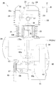
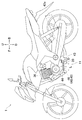
- FIG. 1 is a side view of a motorcycle according to a first embodiment.
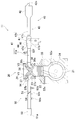
- FIG. 2 is a plan view of the engine unit of the motorcycle of FIG. 1, partially showing a cross section.
- Fig. 2 is a schematic diagram showing an engine unit of the motorcycle shown in Fig. 1.
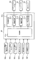
- FIG. 2 is a control block diagram of the motorcycle of FIG. 1.
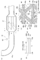
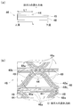
- FIG. 2 is a diagram showing an exhaust passage portion and an upstream catalyst of the engine unit of the motorcycle of FIG. 1, (a) is a partial cross-sectional view, (b) is a schematic diagram showing the structure of each layer of the upstream catalyst, ) Is a sectional view taken along line XX in FIG.
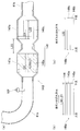
- FIG. 5A is a view showing a modification of the upstream catalyst in FIG. 5A, FIG.
- FIG. 5B is a schematic view showing the structure of each layer of the upstream catalyst
- FIG. 5C is a sectional view taken along line XX in FIG. It is a surface showing a part of it.
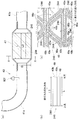
- FIG. 5A is a view showing a modification of the upstream catalyst in FIG. 5A
- FIG. 5B is a schematic view showing the structure of each layer of the upstream catalyst
- FIG. 5C is a sectional view taken along line XX in FIG. It is a surface showing a part of it.
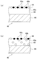
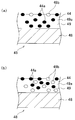
- FIG. (A) And (b) is a fragmentary sectional view which shows the exhaust passage part of an engine unit, and the modification of a catalyst. It is a mimetic diagram showing the saddle riding type vehicle of this embodiment. It is a typical fragmentary sectional view of the upstream catalyst which shows an example of the catalyst layer of this embodiment. It is a typical fragmentary sectional view of the upstream catalyst which shows an example of the catalyst layer of this embodiment, and a phosphorus chemical reaction part. It is a typical fragmentary sectional view of the upstream catalyst which shows an example of the catalyst layer of this embodiment, and a phosphorus chemical reaction part.
- the saddle riding type vehicle 1 is equipped with an engine unit 11.
- the engine unit 11 includes an engine body 20, an exhaust passage portion 43, and an upstream catalyst 46.
- the engine body 20 has a combustion chamber 36.
- the exhaust passage 43 has a discharge port 42e that discharges exhaust gas to the atmosphere.
- the exhaust passage portion 43 flows exhaust gas from the combustion chamber 36 to the discharge port 42e.
- the upstream catalyst 46 is the most upstream catalyst in the exhaust gas flow direction in the exhaust passage portion 43.
- the upstream catalyst 46 has a catalyst layer 49.
- the catalyst layer 49 has a higher function of purifying exhaust gas than a function of chemically reacting with phosphorus contained in the exhaust gas.
- the catalyst layer 49 includes a noble metal.
- the upstream catalyst 46 has a phosphorus adhesion reducing portion 44.
- the phosphorus adhesion reducing unit 44 reduces the adhesion of phosphorus to the catalyst layer 49.
- the phosphorus adhesion reducing part 44 includes either a phosphorus chemical reaction part or a phosphorus barrier layer.
- the catalyst layer 49 having a phosphorus chemical reaction part is formed such that the maximum length L in the exhaust gas flow direction is longer than the maximum length D orthogonal to the exhaust gas flow direction.
- the phosphorus chemical reaction portion is disposed at least in a portion from the upstream end to the center of the catalyst layer 49 in the flow direction of the exhaust gas.
- the phosphorus chemical reaction part has a higher function of chemically reacting with phosphorus contained in the exhaust gas than the function of purifying the exhaust gas.
- the base material 48 to be laminated is formed of a metal.
- the phosphorus barrier layer is disposed on more than half of the entire surface of the catalyst layer 49.
- the phosphorus barrier layer has a function that makes it difficult to chemically react with phosphorus.
- the saddle riding type vehicle 1 of the present embodiment has the following characteristics.
- the upstream catalyst 46 is disposed at a position closest to the combustion chamber 36.
- the time required to activate the upstream catalyst 46 can be shortened. Therefore, the exhaust gas purification performance of the saddle riding type vehicle 1 can be improved.
- the upstream catalyst 46 has a phosphorus adhesion reducing portion 44.
- the phosphorus adhesion reducing unit 44 reduces the adhesion of phosphorus to the catalyst layer 49.
- the phosphorus adhesion reducing part 44 includes either (A) a phosphorus chemical reaction part or (B) a phosphorus barrier layer.
- the catalyst layer 49 of the upstream catalyst 46 having the phosphorus chemical reaction part is formed such that the maximum length L in the exhaust gas flow direction is longer than the maximum length D orthogonal to the exhaust gas flow direction.
- the phosphorus chemical reaction portion is disposed at least in a portion from the upstream end of the catalyst layer 49 to the center of the catalyst layer 49 in the exhaust gas flow direction. That is, the phosphorus chemical reaction unit is disposed at least upstream of the catalyst layer 49 in the exhaust gas flow direction.
- the phosphorus chemical reaction part has a higher function of chemically reacting with phosphorus contained in the exhaust gas than the function of purifying the exhaust gas. A large amount of phosphorus adheres upstream of the catalyst layer 49 in the flow direction of the exhaust gas.
- the phosphorus chemical reaction unit can capture phosphorus contained in the exhaust gas by chemically reacting with a large amount of phosphorus contained in the exhaust gas upstream of the catalyst layer 49 in the flow direction of the exhaust gas. And it can suppress that phosphorus adheres to the catalyst layer 49.
- the base material 48 to be laminated is formed of a metal. That is, the base material 48 and the catalyst layer 49 can be formed thinner than when the base material 48 is formed of ceramic.
- the catalyst layer 49 has a phosphorus barrier layer disposed on half or more of the entire surface. Since the base material 48 and the catalyst layer 49 are thin, it is easy to form a phosphorus barrier layer on the surface of the catalyst layer 49.
- the phosphorus barrier layer has a function that makes it difficult to chemically react with phosphorus.
- the phosphorus barrier layer can pass phosphorus. And it can suppress that phosphorus adheres to the catalyst layer 49.
- the saddle riding type vehicle 1 of the present embodiment of the present invention is a motorcycle
- the description of the same part as the above-described embodiment of the present invention is omitted.
- the specific examples of the embodiments of the present invention include all the embodiments of the present invention described above.
- the front-rear direction is a vehicle front-rear direction viewed from a rider seated on a seat 9 (described later) of the motorcycle 1
- the left-right direction is a vehicle viewed from a rider seated on the seat 9. It is the left-right direction.
- the vehicle left-right direction is the same as the vehicle width direction.
- the arrow F, arrow B, arrow U, arrow D, arrow L, and arrow R in the figure of this embodiment represent the front, back, upper, lower, left, and right, respectively.
- FIG. 1 is a side view of the motorcycle according to the first embodiment.
- FIG. 2 is a plan view of the engine unit of the motorcycle according to the first embodiment, showing a part thereof in cross section.
- FIG. 3 is a schematic diagram showing an engine unit of the motorcycle according to the first embodiment.
- the motorcycle 1 of the first embodiment is a so-called sports type motorcycle.
- the engine unit of this embodiment may be applied to an on-road type motorcycle or an off-road type motorcycle.
- the motorcycle 1 includes a front wheel 2, a rear wheel 3, and a body frame 4.
- the vehicle body frame 4 has a head pipe 4a.
- the vehicle body frame 4 is disposed along the front-rear direction.
- the number of front wheels 2 is one, but two or more.
- the head pipe 4 a is disposed at the front portion of the vehicle body frame 4.
- a steering shaft (not shown) is rotatably inserted into the head pipe 4a.
- a handle unit 5 is provided on the upper portion of the steering shaft.
- the handle unit 5 has a handle bar 12.
- Grips 13 are provided at both ends of one handle bar 12.
- a display device 14 is arranged in the vicinity of the handle unit 5. The display device 14 displays vehicle speed, engine speed, various warnings, and the like.
- a pair of left and right front forks 6 are supported at the bottom of the steering shaft.
- the front wheel 2 is rotatably supported at the lower end of the front fork 6.
- the front fork 6 is configured to absorb an impact in the vertical direction.
- a pair of swing arms 7 are swingably supported on the body frame 4.
- the rear end portion of the swing arm 7 supports the rear wheel 3.
- a rear suspension 8 is attached to each swing arm 7.
- One end of the rear suspension 8 is attached to a position behind the swing center of the swing arm 7.
- the rear suspension 8 is configured to absorb an impact in the vertical direction.
- the vehicle body frame 4 supports the seat 9 and the fuel tank 10.
- the fuel tank 10 is disposed in front of the seat 9.
- the vehicle body frame 4 supports the engine unit 11.
- the engine unit 11 may be directly connected to the vehicle body frame 4 or indirectly connected thereto.
- the engine unit 11 is disposed below the fuel tank 10.
- the engine unit 11 is disposed behind the front wheel 2 and in front of the rear wheel 3 when viewed in the left-right direction.
- the vehicle body frame 4 supports a battery (not shown).
- the battery supplies electric power to electronic devices such as an ECU (Electronic Control Unit) 90 (see FIG. 4) that controls the engine unit 11 and various sensors.
- ECU Electronic Control Unit
- the engine unit 11 is a natural air-cooled engine unit.
- the engine unit 11 is a single cylinder engine.
- the engine unit 11 is a 4-stroke engine.
- the 4-stroke engine is an engine that repeats an intake stroke, a compression stroke, a combustion stroke (expansion stroke), and an exhaust stroke.
- the engine unit 11 includes an engine body 20, an exhaust device 40, and a power transmission unit 60 (see FIG. 2).
- the exhaust device 40 includes an exhaust passage portion 43 and a catalyst (upstream catalyst) 46.
- the engine unit 11 has an upstream oxygen sensor (upstream oxygen detection member) 92f. Further, the engine unit 11 has an intake device 50 (see FIG. 3). Further, the upstream catalyst 46 has a phosphorus adhesion reducing portion 44 (see FIG. 3).
- the upstream catalyst 46 is the most upstream catalyst in the exhaust gas flow direction in the exhaust passage portion 43.
- the engine body 20 includes a crankcase portion 21, a cylinder portion 28, a generator 29, and a starter motor (not shown).
- the cylinder portion 28 includes a cylinder body 22, a cylinder head 23, and a head cover 24.
- the crankcase portion 21 includes a crankcase 21a, a crankshaft 34, and an oil pan (not shown).
- the crankcase 21a and the oil pan may be integrally formed.
- the crankcase 21a accommodates a power transmission unit 60, a generator 29, and a starter motor.
- a crankshaft 34 is accommodated in the crankcase 21a.
- the crankshaft 34 is rotatably supported by the crankcase portion 21.
- a center line Cr of the crankshaft 34 is referred to as a crankshaft line Cr.
- the crank axis Cr is along the left-right direction. More specifically, the crank axis Cr is parallel to the left-right direction.
- a generator 29 is attached to the left end of the crankshaft 34.
- the power transmission unit 60 is accommodated in the crankcase 21a.
- the power transmission unit 60 is connected to the right end portion of the crankshaft 34. In FIG. 2, only some of the components of the power transmission unit 60 are indicated by broken lines.
- the power transmission unit 60 includes a transmission unit 61 and a clutch unit 62.
- the transmission unit 61 is a stepped transmission that includes a main shaft 63 and a drive shaft 64.
- the crankshaft 34 and the main shaft 63 are connected via a clutch portion 62.
- the clutch unit 62 switches between a state in which power can be transmitted from the crankshaft 34 to the main shaft 63 and a state in which it is disconnected.
- the main shaft 63 has a plurality of transmission gears 63a.
- the drive shaft 64 has a plurality of transmission gears 64a.
- the transmission gear 63a and the transmission gear 64a are selected as a pair of gears so as to have a predetermined transmission ratio.
- the selected pair of gears are meshed so that power can be transmitted from the main shaft 63 to the drive shaft 64. Any one of the gears other than the selected pair of gears is idle with respect to the main shaft 63 or the drive shaft 64. That is, power is transmitted from the main shaft 63 to the drive shaft 64 only by the selected pair of transmission gears.
- the transmission gear 63a and the transmission gear 64a are power transmission mechanisms.
- the left end portion of the drive shaft 64 protrudes outside from the crankcase 21a.
- a sprocket 67 is provided at the left end of the drive shaft 64.
- a chain 68 is wound around a sprocket 67 of the drive shaft 64 and a sprocket (not shown) of the rear wheel 3. Power is transmitted from the drive shaft 64 to the rear wheel 3 by the chain 68.
- Oil is stored in the oil pan.
- the crankcase portion 21 has an oil pump (not shown) that sucks up the oil stored in the oil pan. The oil sucked up by the oil pump lubricates the crankcase portion 21.
- the crankcase portion 21 communicates with a chain chamber 33b of a cylinder body 22 and a chain chamber 33a of a cylinder head 23, which will be described later.
- the oil circulates in the chain chamber 33 b of the cylinder body 22 and the chain chamber 33 a of the cylinder head 23.
- oil lubricates the valve operating mechanism 30 mentioned later accommodated in the cylinder head 23 which the cylinder part 28 has.
- a part of the engine body 20 and a part of the transmission part 61 are accommodated in the crankcase part 21.
- a part of the engine body 20 is lubricated with oil.
- a part of the transmission unit 61 is lubricated with oil. That is, the oil that lubricates the engine body 20 and the oil that lubricates the transmission unit 61 are common oils.
- a part of the engine body 20 and the clutch part 62 are accommodated in the crankcase part 21.
- a part of the engine body 20 is lubricated with oil.
- the clutch part 62 is lubricated with oil. That is, the oil that lubricates the engine body 20 and the oil that lubricates the clutch portion 62 are common oils.
- the oil that lubricates the engine body 20 is preferably oil having an evaporation temperature higher than the wall surface temperature of the engine body 20.
- the cylinder portion 28 includes the cylinder body 22, the cylinder head 23, and the head cover 24.
- the cylinder body 22 is attached to the upper end portion of the crankcase portion 21.
- the cylinder head 23 is attached to the upper end portion of the cylinder body 22.
- the head cover 24 is attached to the upper end portion of the cylinder head 23.
- a fin portion 25 is formed on the surface of the cylinder body 22.
- the fin portion 25 is formed on substantially the entire circumference of the cylinder body 22.
- a fin portion 26 is formed on the surface of the cylinder head 23.
- the fin portion 26 is formed on substantially the entire circumference of the cylinder head 23.
- the fin portions 25 and 26 are constituted by a plurality of fins.
- the fin portions 25 and 26 dissipate heat generated in the engine body 20.
- the cylinder body 22 has a cylinder hole 22a.
- a piston 35 is accommodated in the cylinder hole 22a so as to be able to reciprocate.
- the piston 35 is connected to the crankshaft 34 via a connecting rod 35a.
- the center line of the cylinder hole 22a is referred to as a cylinder axis Cy.
- the cylinder axis Cy is along the vertical direction.
- the cylinder axis Cy is inclined in the front-rear direction with respect to the up-down direction.
- the cylinder axis Cy is inclined such that the cylinder portion 28 is inclined forward. That is, the cylinder axis Cy is inclined so as to go forward as it goes upward.
- the tilt angle of the cylinder axis Cy with respect to the vertical direction is defined as a tilt angle ⁇ cy.
- the inclination angle ⁇ cy is not less than 0 degrees and not more than 45 degrees.
- the inclination angle ⁇ cy is not limited to the angle shown in FIG.
- a combustion chamber 36 is formed in the cylinder portion 28.
- Each combustion chamber 36 is formed by the lower surface of the cylinder head 23, the cylinder hole 22 a, and the upper surface of the piston 35.
- the combustion chamber 36 may have a configuration including a main combustion chamber and a sub-combustion chamber connected to the main combustion chamber.
- a straight line passing through the crank axis Cr and parallel to the up-down direction is defined as a straight line La1.
- the combustion chamber 36 is disposed in front of the straight line La1 when the motorcycle 1 is viewed in the left-right direction. That is, when the motorcycle 1 is viewed in the left-right direction, the combustion chamber 36 is disposed in front of the crank axis Cr.
- a cylinder intake passage portion 37 and a cylinder exhaust passage portion 38 are formed in the cylinder head 23.
- path part means the structure which forms a path
- the path means a space through which gas or the like passes.
- an intake port 37a and an exhaust port 38a are formed in a wall portion forming the combustion chamber 36.
- the number of intake ports 37a and exhaust ports 38a provided for one combustion chamber 36 is one.
- the number of intake ports 37a provided for one combustion chamber 36 may be two or more. For example, when two intake ports 37a are provided for one combustion chamber 36, the cylinder intake passage portion 37 is formed in a bifurcated shape.
- the number of exhaust ports 38a provided for one combustion chamber 36 may be two or more.
- the cylinder exhaust passage portion 38 is formed in a bifurcated shape.
- An intake port 37 b is formed on the outer surface behind the cylinder head 23.
- An exhaust port 38 b is formed on the outer surface in front of the cylinder head 23.
- the cylinder intake passage portion 37 is formed from the intake port 37a to the intake port 37b.
- the number of intake ports 37b and exhaust ports 38b provided for one combustion chamber 36 is one.
- the number of intake ports 37b provided for one combustion chamber 36 may be two or more.
- the number of exhaust ports 38b provided for one combustion chamber 36 may be two or more.
- the cylinder exhaust passage portion 38 is formed from the exhaust port 38a to the exhaust port 38b.
- the air supplied to the combustion chamber 36 passes through the cylinder intake passage portion 37. Exhaust gas discharged from the combustion chamber 36 passes through the cylinder exhaust passage portion 38.
- the cylinder intake passage portion 37 is provided with an intake valve V1.
- An exhaust valve V ⁇ b> 2 is disposed in the cylinder exhaust passage portion 38.
- the intake port 37a is opened and closed by driving the intake valve V1.
- the exhaust port 38a is opened and closed by driving the exhaust valve V2.
- An intake passage portion 51 described later is connected to the intake port 37 b of the cylinder intake passage portion 37.
- An exhaust pipe 41 described later is connected to the exhaust port 38 b of the cylinder exhaust passage 38.
- a valve mechanism 30 is accommodated in the cylinder head 23.
- the valve mechanism 30 opens and closes the intake valve V1 and the exhaust valve V2.
- the valve mechanism 30 includes a cam shaft 31.
- the cam shaft 31 is disposed along the left-right direction.
- the cam shaft 31 is rotatably supported by the cylinder head 23.
- the cylinder head 23 is provided with a chain chamber 33a.
- the cylinder body 22 is provided with a chain chamber 33b.
- the chain chamber 33a of the cylinder head 23 and the chain chamber 33b of the cylinder body 22 communicate with each other.
- the left end portion of the cam shaft 31 is disposed in the chain chamber 33b.
- the sprocket 32 is provided at the left end portion of the cam shaft 31.
- a sprocket is provided at the left end portion of the crankshaft 34.
- a timing chain (not shown) is wound around the sprocket 32 and the sprocket of the crankshaft 34.
- the timing chain is disposed in the chain chamber 33 a of the cylinder head 23 and the chain chamber 33 b of the cylinder body 22.
- the timing chain transmits the rotation of the crankshaft 34 to the valve mechanism 30.
- the camshaft 31 rotates.
- the intake valve V1 and the exhaust valve V2 are opened and closed.
- the engine body 20 has an engine rotation speed sensor 92a and an engine temperature sensor 92c (see FIG. 4).
- the engine rotation speed sensor 92a detects the rotation speed of the crankshaft 34, that is, the engine rotation speed.
- the engine temperature sensor 92c detects the temperature of the engine body 20 (the temperature of the cylinder body 22).
- the intake device 50 of the motorcycle 1 of the first embodiment will be described.
- the upstream means upstream in the air flow direction.
- the downstream means downstream in the air flow direction.
- the intake device 50 has an intake passage portion 51.
- the intake passage 51 has an air inlet 51a that faces the atmosphere.
- the air inlet 51 a is formed at the upstream end of the intake passage 51.
- the intake passage 51 is provided with an air cleaner 52 for purifying air.
- the downstream end of the intake passage portion 51 is connected to an intake port 37 b formed on the rear surface of the cylinder head 23.
- the air inlet 51a sucks air from the atmosphere.
- the air that has flowed into the intake passage 51 from the air inlet 51 a is supplied to the engine body 20.
- an injector 94 is disposed in the intake passage 51.
- the injector 94 injects fuel into the air in the intake passage portion 51.
- the injector 94 is connected to a fuel tank (not shown) via a fuel hose (not shown).
- a fuel pump 95 (see FIG. 4) is disposed inside the fuel tank. The fuel pump 95 pumps the fuel in the fuel tank to the fuel hose.
- a throttle valve 54 is arranged in the intake passage 51.
- the opening degree of the throttle valve 54 is changed by the rider operating the accelerator grip (not shown).
- the intake passage 51 is provided with a throttle opening sensor (throttle position sensor) 92b, an intake pressure sensor 92d, and an intake air temperature sensor 92e.
- the throttle opening sensor 92b outputs a signal representing the throttle opening by detecting the position of the throttle valve 54.
- the throttle opening is the opening of the throttle valve 54.
- the intake pressure sensor 92d detects the internal pressure of the intake passage 51.
- the intake air temperature sensor 92e detects the temperature of the air in the intake passage portion 51.
- the exhaust device 40 of the motorcycle 1 according to the first embodiment will be described.
- the upstream means upstream in the flow direction of exhaust gas.
- the downstream means downstream in the flow direction of the exhaust gas.
- the exhaust device 40 has an exhaust passage portion 43 and a catalyst 46. That is, the engine unit 11 includes the exhaust passage portion 43 and the catalyst 46.
- the exhaust passage portion 43 includes the aforementioned cylinder exhaust passage portion 38, the exhaust pipe 41, the silencer 42, and the casing 47.
- the silencer 42 has a discharge port 42e facing the atmosphere.
- the exhaust passage portion 43 is a structure that forms a space through which exhaust gas flows from the combustion chamber 36 to the discharge port 42e.
- the exhaust pipe 41 has an upstream exhaust pipe 41a and a downstream exhaust pipe 41b.
- the upstream exhaust pipe 41 a is disposed upstream of the casing 47.
- the downstream exhaust pipe 41 b is disposed downstream from the casing 47.
- the upstream end portion of the upstream exhaust pipe 41 a is connected to the cylinder exhaust passage portion 38.
- the upstream end portion of the upstream exhaust pipe 41a may be inserted into the cylinder exhaust passage portion 38.
- Exhaust gas flows into the upstream end of the upstream exhaust pipe 41a.
- the downstream end of the downstream exhaust pipe 41 b is inserted into the silencer 42 and disposed in the silencer 42.
- the upstream exhaust pipe 41a and the downstream exhaust pipe 41b are drawn in a straight line for simplification, but the upstream exhaust pipe 41a and the downstream exhaust pipe 41b are not in a straight line.
- An upstream oxygen sensor 92 f is disposed between the combustion chamber 36 and the upstream catalyst 46 in the exhaust passage 43. Specifically, an upstream oxygen sensor 92f is disposed in the upstream exhaust pipe 41a. The upstream oxygen sensor 92f detects the oxygen concentration of the exhaust gas passing through the upstream exhaust pipe 41a.
- the upstream oxygen sensor 92f may be a linear A / F sensor.
- the linear A / F sensor outputs a linear detection signal corresponding to the oxygen concentration of the exhaust gas. In other words, the linear A / F sensor continuously detects a change in oxygen concentration in the exhaust gas.
- the silencer 42 is configured to suppress pulsating waves of exhaust gas. Thereby, the silencer 42 can reduce the volume of the sound (exhaust sound) generated by the exhaust gas.
- a plurality of expansion chambers and a plurality of pipes communicating the expansion chambers are provided in the silencer 42.
- the downstream end of the downstream exhaust pipe 41 b is disposed in the expansion chamber of the silencer 42.
- the downstream end of the downstream exhaust pipe 41 b may be connected to the upstream end of the silencer 42.
- a discharge port 42e is provided at the downstream end of the silencer 42.
- the exhaust gas that has passed through the silencer 42 is discharged to the atmosphere from the discharge port 42e.
- the discharge port 42e is located behind the crank axis Cr.
- the silencer 42 is supported by the vehicle body frame 4 via the connection member 42c.
- the silencer 42 may be supported by the engine body 20.
- the casing 47 is included in the exhaust passage portion 43.
- the upstream end of the casing 47 is connected to the upstream exhaust pipe 41a.
- the downstream end of the casing 47 is connected to the downstream exhaust pipe 41b.
- the casing 47 is formed in a cylindrical shape.
- the casing 47 includes a catalyst arrangement passage portion 47b, an upstream passage portion 47a, and a downstream passage portion 47c.
- a catalyst 46 is arranged in the catalyst arrangement passage portion 47b.
- the upstream end and the downstream end of the catalyst arrangement passage portion 47 b are at the same positions as the upstream end and the downstream end of the catalyst 46, respectively.
- the same position here is a meaning including the position of the vicinity.
- the area of the cross section perpendicular to the flow direction of the exhaust gas in the catalyst arrangement passage portion 47b is substantially constant in the flow direction of the exhaust gas.
- the upstream passage portion 47a is connected to the upstream end of the catalyst arrangement passage portion 47b.
- the downstream passage portion 47c is connected to the downstream end of the catalyst arrangement passage portion 47b.
- the upstream passage 47a is at least partially tapered.
- the tapered portion has an inner diameter that increases toward the downstream.
- the downstream passage portion 47c is at least partially tapered.
- the tapered portion has an inner diameter that decreases toward the downstream.
- the area of the cross section orthogonal to the flow direction of the exhaust gas in the catalyst arrangement passage portion 47b is defined as S1.
- the area of the cross section orthogonal to the flow direction of the exhaust gas in the exhaust pipe 41 is S2.
- Area S2 is smaller than area S1.
- the upstream catalyst 46 is fixed inside the catalyst arrangement passage portion 47b. That is, the upstream catalyst 46 is disposed in the exhaust passage portion 43.
- the exhaust gas is purified by passing through the upstream catalyst 46.
- the upstream catalyst 46 is in an inactive state and does not exhibit purification performance.
- the upstream catalyst 46 becomes active and exhibits purification performance.
- the upstream catalyst 46 is the most upstream catalyst in the exhaust gas flow direction.
- the upstream catalyst 46 can also be said to be a front catalyst disposed at the foremost position in the exhaust passage 43 disposed in the front-rear direction when the motorcycle 1 is viewed in the left-right direction. All exhaust gas discharged from the exhaust port 38 a of the combustion chamber 36 passes through the upstream catalyst 46.
- the upstream catalyst 46 is a so-called three-way catalyst.
- the three-way catalyst is removed by oxidizing or reducing three substances of hydrocarbon, carbon monoxide, and nitrogen oxide contained in the exhaust gas.
- the three-way catalyst is one type of redox catalyst.
- FIG. 5A is a partial cross-sectional view of the exhaust passage and the upstream catalyst of the engine unit of FIG.
- FIG. 5B is a schematic view showing the structure of each layer of the upstream catalyst.
- FIG. 5C is a cross-sectional view taken along line XX of FIG.
- the upstream oxygen sensor 92f is disposed in the upstream exhaust pipe 41a.
- the catalyst 46 is disposed in the casing 47.
- the upstream oxygen sensor 92 f is disposed upstream of the catalyst 46 in the exhaust passage portion 43.
- each layer of the upstream catalyst 46 includes a base material 48 and a catalyst layer 49.
- the base material 48 is a metal base material.
- the substrate 48 is preferably made of a heat resistant material.
- the base material 48 is a porous structure.
- the porous structure has a large number of holes penetrating in the exhaust gas flow direction.
- the base material 48 includes a metal corrugated plate 48a and a metal flat plate 48b.
- the corrugated plate 48a and the flat plate 48b are metal foils having a thickness of several tens of ⁇ m using a heat-resistant alloy.
- the base material 48 is formed in a cylindrical shape by alternately winding and corrugating the corrugated plates 48a and the flat plates 48b.
- the base material 48 is inserted into the cylindrical catalyst arrangement passage portion 47b.
- a large number of cells 46 a partitioned by corrugated plates 48 a and flat plates 48 b are formed on the base material 48.
- the cell 46a is a hole.
- the shape of the cross section orthogonal to the longitudinal direction of the cell 46a is a substantially triangular shape having apexes at three portions where the corrugated plate 48a and the flat plate 48b abut.
- the upstream catalyst 46 is arranged in the catalyst arrangement passage portion 47b so that the longitudinal direction of the cell 46a is along the flow direction of the exhaust gas.
- the cell 46a penetrates from upstream to downstream in the exhaust gas flow direction.
- the maximum width of the cross section of the cell 46a in the direction orthogonal to the exhaust gas flow direction is sufficiently smaller than the length of the exhaust gas flow direction.
- the exhaust gas flowing into the upstream catalyst 46 passes through the cell 46a.
- the catalyst layer 49 is provided by being laminated on the surface of the base material 48. That is, the catalyst layer 49 is provided by being laminated on the surfaces of the corrugated plate 48a and the flat plate 48b.
- FIG. 12A is a schematic partial cross-sectional view of the upstream catalyst 46 showing an example of the catalyst layer 49.
- the structure of the catalyst layer 49 is not restricted to the structure shown to Fig.12 (a).
- the catalyst layer 49 has a noble metal layer 49b composed of a carrier 49a and a noble metal 49b.
- the carrier 49 a is provided between the noble metal layer 49 b and the base material 48.
- the carrier 49 a is provided for attaching the noble metal 49 b to the base material 48.
- the carrier 49a is made of, for example, an inorganic oxide such as silica, alumina, or titania compound.
- the carrier 49a may contain a substance having an action of purifying exhaust gas.
- the support 49a does not contain a noble metal.
- the carrier 49a is formed on the surface of the cell 46a by, for example, a coating method called wash coat. Wash coat, for example, porous ⁇ ?
- a carrier 49a made of an alumina layer is formed.
- the noble metal layer 49b is formed dispersed on the surface of the carrier 49a. Examples of the noble metal 49b include platinum, palladium, rhodium, ruthenium, gold, silver, osmium, iridium and the like.
- the noble metal 49b remove any of hydrocarbons, carbon monoxide, and nitrogen oxides.
- the noble metal 49b is attached to the carrier 49a.
- the noble metal 49b may be included in the catalyst layer 49 in the form of a noble metal alloy.
- the noble metal 49b may be directly attached to the carrier 49a, or may be attached to the carrier 49a via a substance other than the noble metal.
- the noble metal 49b may be chemically bonded to the carrier 49a.
- the noble metal 49b hardly blocks the micropores of the carrier 49a.
- the catalyst layer 49 is formed as follows, for example. Specifically, for example, after the carrier 49a is formed on the substrate 48, a solution containing the noble metal 49b is applied to the surface of the carrier 49a.
- the base material 48 on which the carrier 49a is formed is immersed in a solution containing the noble metal 49b.
- the catalyst layer 49 may be formed by immersing the noble metal 49b in the surface layer of the carrier 49a.
- the noble metal 49b of the noble metal layer 49b purifies the exhaust gas. That is, the exhaust gas contacts with the noble metal layer 49b and is purified when passing through the cell 46a. More specifically, the reaction between the catalyst layer 49 and the exhaust gas proceeds not only at the interface between the exhaust gas and the catalyst layer 49 but also inside the catalyst layer 49.
- the catalyst layer 49 is formed with a constant thickness (for example, a thickness of about 5 to 30 ⁇ m) in order to utilize the reaction that proceeds in the inside thereof. That is, the catalyst layer 49 includes the noble metal 49b.
- the catalyst layer 49 has a higher function of purifying exhaust gas than a function of chemically reacting with phosphorus contained in the exhaust gas.
- the catalyst layer 49 has a phosphorus adhesion reducing portion 44 on the surface thereof.
- the phosphorus adhesion reducing unit 44 reduces the adhesion of phosphorus to the catalyst layer 49.
- the phosphorus adhesion reducing portion 44 is provided by being laminated on the surface of the noble metal layer 49b.
- the phosphorus adhesion reducing part 44 is a phosphorus chemical reaction part 44 composed of a phosphorus reactive substance 44a (see FIG. 14).
- the phosphorus reactant 44a is a substance that chemically reacts with phosphorus contained in the exhaust gas.
- the phosphorus chemical reaction unit 44 has a higher function of chemically reacting with phosphorus contained in the exhaust gas than a function of purifying the exhaust gas.
- the phosphorus reactive substance 44a is a phosphorus adsorbing substance that is a substance that adsorbs phosphorus by chemically reacting with phosphorus contained in the exhaust gas.
- the phosphorus reactant is, for example, a metal oxide having an isoelectric point greater than 3. More specifically, the phosphorus reactant 44a is a metal oxide having at least one selected from U, Mn, Sn, Ti, Fe, Zr, Ce, Al, Y, Zn, La, and Mg.
- the phosphorus compound in the exhaust gas exists as phosphoric acid having an isoelectric point near 1.
- a metal oxide having an isoelectric point greater than 3 has a large difference in isoelectric point between the phosphorus compound and the metal oxide, and thus the phosphorus compound is easily adsorbed by the metal oxide. That is, these phosphorus reactants 44a adsorb phosphorus by the action of the isoelectric value of the metal oxide.
- the phosphorus reactive substance 44a may be a substance having high reactivity with phosphorus.
- the phosphorus reactant 44a may be a metal oxide having at least one selected from Ba, Sr, Ca, La, Pr, Na, and Zr.
- each layer of the upstream catalyst 46 may include a base material 48 and a catalyst layer 49.
- FIG. 12B is a schematic partial cross-sectional view of the upstream catalyst 46 showing an example of the catalyst layer 49.
- the configuration of the catalyst layer 49 is not limited to the configuration shown in FIG.
- the carrier 49 a is provided for attaching a noble metal to the base material 48.
- the catalyst layer 49 is provided by being laminated on the surface of the base material 48.
- the carrier 49 a is provided for attaching the noble metal 49 b dispersed therein to the base material 48.
- the catalyst layer 49 has a structure in which the noble metal 49b is dispersed inside and on the surface of the carrier 49a.
- the catalyst layer 49 may be formed by immersing the base material 48 in a solution containing the material constituting the carrier 49a and the noble metal 49b.
- the noble metal 49b may exist not only inside the carrier 49a but also on the surface of the catalyst layer 49.
- the noble metal 49b in the catalyst layer 49 purifies the exhaust gas.
- the catalyst layer 49 may have a structure in which the noble metal 49b is dispersed only inside the carrier 49a. That is, the noble metal 49b may not be disposed on the surface of the carrier 49a.
- the catalyst layer 49 has a phosphorus chemical reaction portion 44 on the surface thereof.
- the phosphorus chemical reaction part 44 is formed in at least a part from the upstream end to the center of the catalyst layer 49 in the exhaust gas flow direction.
- the phosphorus chemical reaction unit 44 shown in FIG. 6 is configured by stacking a phosphorus reaction material on the surface of the catalyst layer 49.
- FIGS. 13A and 13B are schematic partial cross-sectional views of the upstream catalyst 46 showing two examples of the catalyst layer 49 and the phosphorus chemical reaction unit 44.
- the structure of the catalyst layer 49 and the phosphorus chemical reaction part 44 is not restricted to the structure shown to Fig.13 (a) and FIG.13 (b).
- the catalyst layer 49 includes a carrier 49a and a noble metal 49b.
- the phosphorus chemical reaction unit 44 includes a phosphorus reaction material 44a.
- the phosphorus reactant 44a and the noble metal 49b may be disposed only on the surface layer of the catalyst layer 49.
- a solution containing the phosphorus reactive substance 44a and the noble metal 49b is applied to the surface of the carrier 49a.
- the base material 48 on which the carrier 49a is formed is immersed in a solution containing the phosphorus reactant 44a and the noble metal 49b.
- the phosphorus chemical reaction part 44 and the catalyst layer 49 may be formed by immersing the phosphorus reaction substance 44a and the noble metal 49b into the surface layer of the support 49a. Further, as shown in FIG.
- the phosphorus reactant 44a may be disposed only on the surface layer of the catalyst layer 49, and the noble metal 49b may be dispersed and disposed inside the carrier 49a.
- the catalyst layer 49 may be formed by immersing the base material 48 in a solution containing the material constituting the carrier 49a and the noble metal 49b.
- the noble metal 49b may exist not only inside the carrier 49a but also on the surface of the catalyst layer 49.
- a solution containing the phosphorus reactant 44 a is applied to the surface of the catalyst layer 49.
- the catalyst layer 49 is immersed in a solution containing the phosphorus reactant 44a.
- the phosphorus reactant 44a may be disposed only on the surface layer of the catalyst layer 49, and the noble metal 49b may be disposed only inside the carrier 49a. That is, the noble metal 49b may not be disposed on the surface of the carrier 49a.
- the catalyst layer 49 may have a phosphorus chemical reaction section 44 inside thereof.
- the phosphorus chemical reaction part 44 is formed in at least a part from the upstream end to the center of the catalyst layer 49 in the exhaust gas flow direction.
- the phosphorus chemical reaction unit 44 shown in FIG. 7 is configured by dispersing a phosphorus reactant 44 a in a catalyst layer 49. That is, the carrier 49a (see FIG. 14) of the catalyst layer 49 adheres the phosphorus reactant 44a dispersed therein.
- FIG. 14A and FIG. 14B are schematic partial cross-sectional views of the upstream catalyst 46 showing two examples of the catalyst layer 49 and the phosphorus chemical reaction unit 44.
- the structure of the catalyst layer 49 and the phosphorus chemical reaction part 44 is not restricted to the structure shown to Fig.14 (a) and FIG.14 (b).
- the catalyst layer 49 includes a carrier 49a and a noble metal 49b.
- the phosphorus chemical reaction unit 44 includes a phosphorus reaction material 44a.
- the phosphorus reactant 44a may be dispersed and disposed inside the support 49a, and the noble metal 49b may be disposed only on the surface layer of the catalyst layer 49.
- the carrier 49a and the phosphorus chemical reaction part 44 may be formed on the base material 48 by immersing the base material 48 in a solution containing the material constituting the support 49a and the phosphorus reactant 44a. Good. Thereafter, a solution containing the noble metal 49 b is applied to the surfaces of the carrier 49 a and the phosphorus chemical reaction unit 44.
- the base material 48 on which the carrier 49a and the phosphorus chemical reaction part 44 are formed is immersed in a solution containing the noble metal 49b.
- the catalyst layer 49 may be formed by immersing the noble metal 49b in the surface layer of the carrier 49a and the phosphorus chemical reaction part 44. Further, as shown in FIG. 14B, the phosphorus reactant 44a and the noble metal 49b may be dispersed and arranged inside the carrier 49a. Specifically, for example, even if the catalyst layer 49 and the phosphorus chemical reaction part 44 are formed by immersing the base material 48 in a solution containing the material constituting the support 49a, the noble metal 49b, and the phosphorus reaction substance 44a. Good. In this case, the phosphorus reactant 44a and the noble metal 49b may exist not only inside the support 49a but also on the surface of the catalyst layer 49.
- the phosphorus reactant 44a may be dispersed and arranged inside the catalyst layer 49, and the noble metal 49b may be arranged only inside the carrier 49a. That is, the noble metal 49b may not be disposed on the surface of the carrier 49a. Further, the phosphorus reactant 44a and the noble metal 49b may be disposed only inside the carrier 49a. That is, the phosphorus reactive substance 44a and the noble metal 49b may not be disposed on the surface of the carrier 49a.
- the maximum length of the upstream catalyst 46 in the exhaust gas flow direction is L. That is, the length L is the maximum length of the catalyst layer 49 in the exhaust gas flow direction.
- the length L here does not mean the length in the flow direction of the exhaust gas of only one layer of the catalyst layer 49.
- the length L means the length of the entire catalyst layer 49 in the exhaust gas flow direction.
- D be the maximum length of the upstream catalyst 46 in the direction orthogonal to the flow direction of the exhaust gas. That is, the length D is the maximum length in the direction orthogonal to the exhaust gas flow direction of the catalyst layer 49.
- the length L is longer than the length D.
- the maximum length L of the catalyst layer 49 in the exhaust gas flow direction is longer than the maximum length D of the catalyst layer 49 in the direction orthogonal to the exhaust gas flow direction.
- the shape of the cross section orthogonal to the flow direction of the exhaust gas of the upstream catalyst 46 is, for example, a circular shape.
- the shape of the cross section orthogonal to the flow direction of the exhaust gas of the upstream catalyst 46 may be an elliptical shape in which the horizontal length is longer than the vertical length.
- L1 be the maximum length in the flow direction.
- the length L1 is the length of the phosphorus chemical reaction section 44 in the exhaust gas flow direction.
- the upstream end of the phosphorus chemical reaction unit 44 in the exhaust gas flow direction is at the same position as the upstream end of the catalyst layer 49 in the exhaust gas flow direction.
- the length of the base material 48 or the catalyst layer 49 that forms the upstream catalyst 46 in the exhaust gas flow direction is the upstream catalyst.
- the length L is the same as the length 46 of the exhaust gas in the flow direction. 3 and 5A, the portion of the upstream catalyst 46 where the phosphorus chemical reaction portion 44 is provided is indicated by reference numeral 44 and indicated by a length L1.
- the length L1 is shorter than the length L of the upstream catalyst.
- the downstream end of the phosphorus chemical reaction unit 44 in the exhaust gas flow direction is disposed between the center of the catalyst layer 49 in the exhaust gas flow direction and the downstream end.
- the length L1 may be shorter than the length D of the upstream catalyst 46.
- the upstream catalyst 46 is below the engine body 20 when the motorcycle 1 is viewed in the left-right direction.
- the upstream catalyst 46 is disposed across the straight line La1 when the motorcycle 1 is viewed in the left-right direction.
- a part of the upstream catalyst 46 is disposed in front of the crank axis Cr when the motorcycle 1 is viewed in the left-right direction.
- the upstream catalyst 46 is disposed in front (downward) of the cylinder axis Cy.
- a part of the upstream catalyst 46 is disposed behind the crank axis Cr when the motorcycle 1 is viewed in the left-right direction.
- the entire upstream catalyst 46 may be disposed in front of the crank axis Cr when the motorcycle 1 is viewed in the left-right direction. That is, the upstream catalyst 46 may be disposed in front of the engine body 20 when the motorcycle 1 is viewed in the left-right direction. When the motorcycle 1 is viewed in the left-right direction, at least a part of the upstream catalyst 46 is preferably disposed in front of the crank axis Cr. As a result, the upstream catalyst 46 is disposed closer to the combustion chamber 36. Further, the time required for activating the upstream catalyst 46 can be further shortened. Note that the entire upstream catalyst 46 may be disposed behind the crank axis Cr when the motorcycle 1 is viewed in the left-right direction.
- the upstream catalyst 46 may be disposed rearward (upward) from the cylinder axis Cy.
- a straight line La2 is a straight line orthogonal to the cylinder axis Cy and passing through the crank axis Cr when the motorcycle 1 is viewed in the left-right direction.
- the upstream catalyst 46 is disposed behind (downward) the straight line La2.
- the upstream catalyst 46 may be disposed in front (upward) of the straight line La2. In this case, the upstream catalyst 46 is disposed at a position closer to the combustion chamber 36. Further, the time required for activating the upstream catalyst 46 can be further shortened.
- FIG. 4 is a control block diagram of the motorcycle according to the first embodiment.
- the engine unit 11 includes an engine speed sensor 92a, a throttle opening sensor 92b (throttle position sensor), an engine temperature sensor 92c (see FIG. 4), an intake pressure sensor 92d, an intake temperature sensor 92e, and an upstream It has an oxygen sensor 92f.
- the engine rotation speed sensor 92a detects the rotation speed of the crankshaft 34, that is, the engine rotation speed.
- the throttle opening sensor 92b detects the opening of the throttle valve 54 by detecting the position of the throttle valve 54.
- the opening degree of the throttle valve 54 is referred to as a throttle opening degree.
- the engine temperature sensor 92 c detects the temperature of the engine body 20.
- the intake pressure sensor 92d detects the pressure in the intake passage 51).
- the intake air temperature sensor 92e detects the temperature of the air in the intake passage portion 51.
- the upstream oxygen sensor 92 f detects the oxygen concentration of the exhaust gas that passes through the exhaust passage portion 43.
- the engine unit 11 includes an ECU 90 that controls the engine body 20, as shown in FIG.
- the ECU 90 is connected to various sensors such as an engine rotation speed sensor 92a, an engine temperature sensor 92c, a throttle opening sensor 92b, an intake pressure sensor 92d, an intake air temperature sensor 92e, an upstream oxygen sensor 92f, and a vehicle speed sensor.
- the ECU 90 is connected to an ignition coil 93, an injector 94, a fuel pump 95, a display device 14 (see FIG. 1), and the like.
- the ECU 90 includes a control unit 91a and an operation instruction unit 91b.
- the operation instruction unit 91b includes an ignition drive circuit 91c, an injector drive circuit 91d, and a pump drive circuit 91e.
- the ignition driving circuit 91c, the injector driving circuit 91d, and the pump driving circuit 91e drive the ignition coil 93, the injector 94, and the fuel pump 95, respectively, in response to a signal from the control unit 91a.
- the fuel pump 95 is connected to the injector 94 via a fuel hose.
- fuel in a fuel tank (not shown) is pumped to the injector 94.
- the control unit 91a is, for example, a microcomputer.
- the controller 91a controls the ignition drive circuit 91c, the injector drive circuit 91d, and the pump drive circuit 91e based on the signal from the upstream oxygen sensor 92f and the signal from the engine rotation speed sensor 92a.
- the controller 91a controls the ignition drive circuit 91c to control the ignition timing.
- the controller 91a controls the fuel injection amount by controlling the injector drive circuit 91d and the pump drive circuit 91e.
- the air-fuel ratio of the air-fuel mixture in the combustion chamber 36 is preferably the stoichiometric air-fuel ratio (stoichiometry).
- the controller 91a increases or decreases the fuel injection amount as necessary.
- the controller 91a calculates the basic fuel injection amount based on signals from the engine speed sensor 92a, the throttle opening sensor 92b, the engine temperature sensor 92c, and the intake pressure sensor 92d. Specifically, the intake air amount is calculated using a map in which the intake air amount is associated with the throttle opening and the engine rotational speed, and a map in which the intake air amount is associated with the intake pressure and the engine rotational speed. Ask. Then, based on the intake air amount obtained from the map, the basic fuel injection amount that can achieve the target air-fuel ratio is determined. When the throttle opening is small, a map in which the intake air amount is associated with the intake pressure and the engine speed is used. On the other hand, when the throttle opening is large, a map in which the intake air amount is associated with the throttle opening and the engine speed is used.
- the control unit 91a calculates a feedback correction value for correcting the basic fuel injection amount based on the signal from the upstream oxygen sensor 92f. Specifically, first, based on the signal from the upstream oxygen sensor 92f, it is determined whether the air-fuel mixture is lean or rich. Note that rich means that the fuel is excessive with respect to the stoichiometric air-fuel ratio. Lean means a state where air is excessive with respect to the stoichiometric air-fuel ratio. When determining that the air-fuel mixture is lean, the control unit 91a calculates a feedback correction value so that the next fuel injection amount increases. On the other hand, when determining that the air-fuel mixture is rich, the control unit 91a obtains a feedback correction value so that the next fuel injection amount is reduced.
- control unit 91a calculates a correction value for correcting the basic fuel injection amount based on the engine temperature, the outside air temperature, the outside air pressure, and the like. Furthermore, the control unit 91a calculates a correction value according to the transient characteristics during acceleration and deceleration.
- the controller 91a calculates the fuel injection amount based on the basic fuel injection amount and a correction value such as a feedback correction value. Based on the fuel injection amount thus determined, the fuel pump 95 and the injector 94 are driven. In this way, the ECU 90 processes the signal of the upstream oxygen sensor 92f. Further, the ECU 90 performs combustion control based on a signal from the upstream oxygen sensor 92f.
- the configuration of the motorcycle 1 according to the first embodiment has been described above.
- the motorcycle 1 of the first embodiment has the following features.
- the motorcycle 1 is equipped with an engine unit 11.
- the engine unit 11 includes an engine body 20, an exhaust passage portion 43, and an upstream catalyst 46.
- the engine body 20 includes a cylinder portion 28 having a combustion chamber 36.
- the exhaust passage 43 has a discharge port 42e that discharges exhaust gas to the atmosphere.
- the exhaust passage portion 43 flows exhaust gas from the combustion chamber 36 to the discharge port 42e.
- the upstream catalyst 46 has a catalyst layer 49.
- the upstream catalyst 46 is the most upstream catalyst in the exhaust gas flow direction in the exhaust passage portion 43.
- the upstream catalyst 46 has a catalyst layer 49 containing a noble metal.
- the catalyst layer 49 of the upstream catalyst 46 has a higher function of purifying exhaust gas than a function of chemically reacting with phosphorus contained in the exhaust gas. That is, the upstream catalyst 46 is disposed at a position closest to the combustion chamber 36. In addition, the time required to activate the upstream catalyst 46 can be shortened. Therefore, the exhaust gas purification performance of the motorcycle 1 can be improved
- the upstream catalyst 46 has a phosphorus adhesion reducing portion 44.
- the phosphorus adhesion reducing unit 44 reduces the adhesion of phosphorus to the catalyst layer 49.
- the phosphorus adhesion reducing unit 44 is a phosphorus chemical reaction unit 44.
- the catalyst layer 49 of the upstream catalyst 46 having the phosphorus chemical reaction section 44 is formed such that the length L of the upstream catalyst 46 in the exhaust gas flow direction is longer than the length D perpendicular to the exhaust gas flow direction.
- the cross-sectional area of the upstream catalyst 46 can be reduced by increasing the length L. That is, when the upstream catalyst 46 has the same capacity, the length D can be shortened by increasing the length L.
- the motorcycle 1 can be prevented from being enlarged in the vertical direction. Further, even when the upstream catalyst 46 is disposed in front of the engine body 20, the size of the motorcycle 1 in the front-rear direction can be suppressed.
- the catalyst layer 49 has at least a part thereof a phosphorus chemical reaction part 44 having a function of capturing phosphorus.
- the phosphorus chemical reaction unit 44 is disposed at least in a portion from the upstream end of the catalyst layer 49 to the center of the catalyst layer 49 in the flow direction of the exhaust gas. That is, the phosphorus chemical reaction unit 44 is disposed at least upstream of the catalyst layer 49 in the exhaust gas flow direction.
- the phosphorus chemical reaction unit 44 has a higher function of chemically reacting with phosphorus contained in the exhaust gas than a function of purifying the exhaust gas. A large amount of phosphorus adheres upstream of the catalyst layer 49 in the flow direction of the exhaust gas.
- the phosphorus chemical reaction unit 44 captures phosphorus contained in the exhaust gas by chemically reacting with a large amount of phosphorus contained in the exhaust gas upstream of the catalyst layer 49 in the flow direction of the exhaust gas. And it can suppress that phosphorus adheres to the upstream catalyst 46. Thereby, the dispersion
- the phosphorus chemical reaction unit 44 captures phosphorus contained in the exhaust gas passing through the upstream catalyst 46, thereby delaying the adhesion of phosphorus to the upstream catalyst 46. And compared with the case where the phosphorus chemical reaction part 44 is not arrange
- the upstream catalyst 46 can be arrange
- FIG. Furthermore, by increasing the degree of freedom of the layout of the upstream catalyst 46, the upstream catalyst 46 can be disposed at a position where the time required for activation can be shortened. Therefore, the motorcycle 1 of the first embodiment can reduce the time required for the activation of the upstream catalyst 46 by increasing the degree of freedom in designing the layout of the upstream catalyst 46, and suppress the deterioration of the purification performance of the upstream catalyst 46. And the enlargement of the motorcycle 1 can be suppressed.
- the phosphorus chemical reaction unit 44 is composed of a phosphorus reactant 44a that chemically reacts with phosphorus contained in the exhaust gas. Then, phosphorus contained in the exhaust gas passing through the upstream catalyst 46 chemically reacts with the phosphorus reactant 44 a in the phosphorus chemical reaction unit 44.
- the phosphorus reaction material 44a is, for example, a material that adsorbs phosphorus. In this case, phosphorus contained in the exhaust gas is adsorbed by the chemical reaction of phosphorus in the exhaust gas with the phosphorus reactant 44a.
- the phosphorus reactant 44 a can capture phosphorus by chemically reacting with phosphorus contained in the exhaust gas passing through the upstream catalyst 46. That is, the phosphorus reactant 44 a can suppress the phosphorus contained in the exhaust gas from adhering to the catalyst layer 49. Thereby, the dispersion
- the phosphorus reactant 44 a is disposed only on the surface of the catalyst layer 49, dispersed within the catalyst layer 49, or disposed only within the catalyst layer 49.
- the phosphorus chemical reaction part 44 can be comprised by various manufacturing methods.
- the phosphorus reactive substance 44a is a metal oxide having at least one selected from U, Mn, Sn, Ti, Fe, Zr, Ce, Al, Y, Zn, La, and Mg.
- These phosphorus reactants 44a are metal oxides having an isoelectric point greater than 3. It is considered that the phosphorus compound in the exhaust gas exists as phosphoric acid having an isoelectric point near 1. Since the metal oxide having an isoelectric point greater than 3 has a large difference in isoelectric point between the phosphorus compound and the metal oxide, the phosphorus compound is easily adsorbed by the metal oxide.
- These phosphorus reactants 44a can adsorb phosphorus contained in the exhaust gas passing through the upstream catalyst 46 by the action of the isoelectric value of the metal oxide. That is, these phosphorus reactants 44 a can suppress the phosphorus contained in the exhaust gas from adhering to the catalyst layer 49. Thereby, the dispersion
- the phosphorus reactant 44a is a metal oxide having at least one selected from Ba, Sr, Ca, La, Pr, Na, and Zr. These phosphorus reactive substances 44a are substances having high reactivity with phosphorus. Therefore, the phosphorus reactant 44 a can capture more phosphorus contained in the exhaust gas that passes through the upstream catalyst 46. That is, these phosphorus reactants 44 a can suppress the phosphorus contained in the exhaust gas from adhering to the catalyst layer 49. Thereby, the dispersion
- Engine unit 11 is an engine unit in which the use of oil having a phosphorus compound content greater than 0.08 mass% is specified.
- the engine unit of the saddle-ride type vehicle is designated to use oil having a higher phosphorus compound content than the engine unit of the four-wheeled vehicle. That is, the engine unit 11 of the motorcycle 1 that is a saddle-ride type vehicle emits exhaust gas that contains more phosphorus than a four-wheeled vehicle.
- the phosphorus chemical reaction unit 44 captures phosphorus contained in the exhaust gas passing through the upstream catalyst 46 in order to chemically react with phosphorus contained in the exhaust gas. As a result, it is possible to suppress variations in the exhaust gas purification performance of the motorcycle 1 that discharges exhaust gas containing a large amount of phosphorus compared to a four-wheeled vehicle.
- the engine unit 11 further includes a transmission unit 61.
- the oil that lubricates the engine body 20 and the oil that lubricates the transmission unit 61 are common oils.
- the oil that lubricates the engine body and the oil that lubricates the transmission are often common oils.
- the oil that lubricates the engine body and the oil that lubricates the transmission part are often not common oils. That is, the motorcycle 1 which is a saddle-ride type vehicle uses a larger amount of oil per displacement than an automobile.
- the motorcycle 1 that is a straddle-type vehicle has a higher phosphorus content in the exhaust gas per displacement than an automobile.
- the transmission unit 61 transmits power using transmission gears 63a and 64a which are power transmission mechanisms.
- the oil that lubricates the transmission unit 61 requires a large amount of phosphorus compound as an additive.
- the oil that lubricates the engine body 20 contains a large amount of phosphorus compounds. Therefore, the engine unit 11 discharges exhaust gas containing a large amount of phosphorus.
- the phosphorus chemical reaction unit 44 captures phosphorus contained in the exhaust gas passing through the upstream catalyst 46 in order to chemically react with phosphorus contained in the exhaust gas. Therefore, it is possible to suppress variation in the exhaust gas purification performance of the motorcycle 1 in which the content of phosphorus contained in the exhaust gas per exhaust amount is larger than that of an automobile.
- the engine unit 11 further includes a clutch part 62.
- the oil that lubricates the engine body 20 and the oil that lubricates the clutch portion 62 are common oils.
- the motorcycle 1 that is a saddle-ride type vehicle has a clutch portion 62 so that the motorcycle 1 can move even when the engine is stopped. Further, in the saddle riding type vehicle, the oil that lubricates the engine body and the oil that lubricates the clutch portion are often common oil.
- the motorcycle 1 that is a saddle-ride type vehicle does not use oil in which the clutch portion 62 is slippery. Oils with a low phosphorus compound content are often oils in which the clutch part is slippery.
- Oil with a low phosphorus compound content used in automobiles is not used in the motorcycle 1 that is a saddle-ride type vehicle. That is, the engine unit 11 of the motorcycle 1 that is a saddle-ride type vehicle uses oil having a higher phosphorus compound content than the engine unit of the automobile. That is, the motorcycle 1 which is a saddle-ride type vehicle emits exhaust gas containing a larger amount of phosphorus than an automobile.
- the phosphorus chemical reaction unit 44 captures phosphorus contained in the exhaust gas passing through the upstream catalyst 46 in order to chemically react with phosphorus contained in the exhaust gas. As a result, it is possible to suppress variations in the exhaust gas purification performance of the motorcycle 1 that exhausts exhaust gas containing a large amount of phosphorus compared to an automobile.
- the engine unit 11 is a natural air-cooled engine unit.
- the natural air-cooled engine unit 11 has a high temperature in the combustion chamber 36.
- the natural air-cooled engine unit 11 decomposes more phosphorus compounds in the oil in the combustion chamber 36 than the forced air-cooled engine unit and the water-cooled engine unit.
- the natural air-cooled engine unit emits more exhaust gas containing phosphorus than the forced air-cooled engine unit or the water-cooled engine unit.
- the phosphorus chemical reaction unit 44 captures phosphorus contained in the exhaust gas passing through the upstream catalyst 46 in order to chemically react with phosphorus contained in the exhaust gas. Thereby, even in the motorcycle 1 having the natural air-cooled engine unit 11, variation in exhaust gas purification performance can be suppressed.
- the oil that lubricates the engine body 20 is an oil having an evaporation temperature higher than the wall surface temperature of the engine body 20.
- the amount of the phosphorus compound contained in the oil that lubricates the engine body 20 is decomposed in the combustion chamber 36 can be suppressed.
- the amount of phosphorus contained in the exhaust gas can be suppressed. Thereby, the dispersion
- FIG. 8A is a partial cross-sectional view showing an exhaust passage portion and an upstream catalyst of an engine unit of a motorcycle according to a modification of the first embodiment.
- FIG. 8B and FIG. 8C are schematic views showing the structure of each layer of the upstream catalyst.
- the engine unit of the motorcycle according to the modification of the first embodiment is different from the engine unit 11 of the motorcycle according to the first embodiment in the configuration of the exhaust passage portion 43 and the upstream catalyst 46.
- the configuration other than the exhaust passage 43 and the upstream catalyst 46 is the same as that of the first embodiment.
- the engine unit of the present embodiment includes an exhaust passage portion 143 and a catalyst 146.
- the catalyst 146 has a configuration in which two catalyst pieces 146a and a catalyst piece 146b are arranged close to each other.
- the proximity means that the distance between the catalyst piece 146a and the catalyst piece 146b is shorter than the maximum length of each catalyst piece 146a and the catalyst piece 146b in the exhaust gas flow direction.
- the maximum length of the catalyst piece 146a in the exhaust gas flow direction is defined as a length L21.
- the maximum length of the catalyst piece 146b in the exhaust gas flow direction is defined as a length L22.
- the distance between the catalyst piece 146a and the catalyst piece 146b is a distance L23.
- the distance L23 is shorter than the length L21.
- the distance L23 is shorter than the length L22.
- the exhaust passage portion 143 includes a cylinder exhaust passage portion 38 (see FIG. 3), an upstream exhaust pipe 41a, a downstream exhaust pipe 41b, a first casing 147a, and a second casing 147b.
- the upstream end portion of the upstream exhaust pipe 41 a is connected to the cylinder exhaust passage portion 38.
- the upstream end of the first casing 147a is connected to the upstream exhaust pipe 41a.
- the downstream end of the first casing 147a is connected to the second casing 147b.
- the downstream end of the second casing 147b is connected to the downstream exhaust pipe 41b.
- the downstream end of the downstream exhaust pipe 41b is inserted into the silencer 42 (see FIG. 3).
- the catalyst piece 146a is disposed in the first casing 147a.
- the catalyst piece 146b is disposed in the second casing 147b.
- the configuration of the first casing 147a and the second casing 147b is the same as the configuration of the first casing 47 of the first embodiment, and a description thereof will be omitted.
- the upstream oxygen sensor 92f is disposed in the upstream exhaust pipe 41a.
- the upstream oxygen sensor 92f is disposed upstream of the catalyst 146 in the exhaust passage portion 143.
- each layer of the catalyst piece 146a has a base material 148a and a catalyst layer 149a.
- the catalyst layer 149a is provided by being stacked on the surface of the base material 148a.
- the catalyst layer 149a has a structure in which a noble metal is dispersed in a carrier.
- the carrier carries a noble metal dispersed therein.
- the noble metal in the catalyst layer 149a purifies the exhaust gas.
- the catalyst layer 149a has a phosphorus chemical reaction part 144 on the surface thereof.
- the phosphorus chemical reaction part 144 is provided by being stacked on the surface of the catalyst layer 149a.
- the phosphorus chemical reaction unit 144 is a chemical reaction unit composed of a phosphorus reaction material.
- the length of the catalyst layer 149a in the exhaust gas flow direction is L21. Further, the length from the upstream end to the downstream end of the phosphorus chemical reaction section 144 in the exhaust gas flow direction is L20.
- the upstream end of the phosphorus chemical reaction unit 144 is the same as the upstream end of the catalyst layer 149a. Further, the downstream end of the phosphorus chemical reaction unit 144 is the same as the downstream end of the catalyst layer 149a. Therefore, the length L20 and the length L21 are the same. That is, in the example shown in FIG. 8A, the phosphorus chemical reaction part 144 is laminated on the entire surface of the catalyst layer 149a.
- each layer of the catalyst piece 146b has a base material 148b and a catalyst layer 149b.
- the catalyst layer 149b is provided by being stacked on the surface of the base material 148b.
- the catalyst layer 149b has a structure in which a noble metal is dispersed in a carrier.
- the carrier carries a noble metal dispersed therein.
- the noble metal in the catalyst layer 149b purifies the exhaust gas.
- the length of the catalyst layer 149b in the exhaust gas flow direction is L22.
- the catalyst 146 includes a catalyst layer 149a (see FIG. 8B) and a catalyst layer 149b (see FIG. 8C).
- the catalyst layer 149a and the catalyst layer 149b purify the exhaust gas at the most upstream in the flow direction of the exhaust gas.
- catalyst 146 is an upstream catalyst.
- the catalyst 146 is referred to as an upstream catalyst 146.
- the length of the upstream catalyst 146 in the exhaust gas flow direction is L24.
- the length L24 is the total length of the catalyst piece 146a and the catalyst piece 146b in the exhaust gas flow direction.
- the length of the catalyst piece 146a in the exhaust gas flow direction is the length L21.
- the length of the catalyst piece 146b in the exhaust gas flow direction is the length L22.
- the length L24 is the sum of the length L21 and the length L22.
- the length from the upstream end to the downstream end of the phosphorus chemical reaction unit 144 is L20.
- the length L20 is longer than the length L24 of the upstream catalyst 146 in the exhaust gas flow direction.
- the largest length orthogonal to the flow direction of the exhaust gas of the catalyst piece 146a is D2.
- the maximum length of the catalyst piece 146b orthogonal to the flow direction of the exhaust gas is D2. Accordingly, the maximum length of the catalyst piece 146a and the catalyst piece 146b orthogonal to the flow direction of the exhaust gas is the same.
- the length L20 is preferably longer than the maximum length D2 orthogonal to the flow direction of the exhaust gas of the upstream catalyst 146.
- the composition of the base material of each catalyst piece 146a and catalyst piece 146b may be one type or a plurality of types.
- the noble metal used for each catalyst layer 149a and catalyst layer 149b may be one kind or plural kinds.
- the composition of the carrier used for each catalyst layer 149a and catalyst layer 149b may be one type or a plurality of types.
- Each catalyst layer 149a and catalyst layer 149b may have a structure having a support and a noble metal layer supported on the surface of the support.
- the phosphorus chemical reaction part 144 is formed on the entire catalyst layer 149a.
- the phosphorus chemical reaction part 144 may be formed in a part of the catalyst layer 149a.
- the length L20 from the upstream end to the downstream end in the exhaust gas flow direction of the phosphorus chemical reaction part 144 is longer than half of the length L24.
- the phosphorus chemical reaction part 144 may be formed on at least a part of the catalyst layer 149b from the upstream end of the catalyst layer 149b.
- the phosphorus chemical reaction unit 144 may have a structure in which a phosphorus reactant is dispersed inside the catalyst layer 149a instead of being stacked on the surface of the catalyst layer 149a.
- the phosphorus chemical reaction unit 144 may have a structure in which a phosphorus reaction material is disposed only inside the catalyst layer 149a. Further, the length of the catalyst piece 146a perpendicular to the exhaust gas flow direction and the length of the catalyst piece 146b orthogonal to the exhaust gas flow direction may not be the same. Further, the number of pieces of the catalyst 146 may be three or more.
- the motorcycle according to the modification of the first embodiment has the same effects as the effects described in the first embodiment with respect to the same configuration as the first embodiment. Furthermore, the motorcycle according to the modification of the first embodiment has the following characteristics.
- each catalyst piece 146a, 146b can be freely designed according to the layout. Therefore, the degree of freedom in designing the layout of the upstream catalyst 146 can be increased. Then, the upstream catalyst 146 can be arranged in a layout that can shorten the time required to activate the upstream catalyst 146. Further, the size of the phosphorus chemical reaction part 144 can be freely designed according to the layout. Then, by increasing the size of the phosphorus chemical reaction unit 144, phosphorus can be captured more from the exhaust gas passing through the upstream catalyst 146. Accordingly, it is possible to suppress a decrease in the purification performance of the upstream catalyst 146.
- FIG. 9A is a partial cross-sectional view showing an exhaust passage portion and an upstream catalyst of the engine unit of the motorcycle according to the second embodiment.
- FIG. 9B and FIG. 9C are schematic views showing the structure of each layer of the upstream catalyst.
- the engine unit of the motorcycle according to the second embodiment is different from the engine unit 11 of the motorcycle according to the first embodiment in the configuration of the upstream catalyst 46.
- the configuration other than the upstream catalyst 46 is the same as that of the first embodiment.
- the engine unit of the present embodiment includes an exhaust passage portion 43 and a catalyst 246.
- the catalyst 246 is fixed inside the catalyst arrangement passage portion 47b. That is, the catalyst 246 is disposed in the exhaust passage portion 43.
- the exhaust gas is purified by passing through the catalyst 246.
- the catalyst 246 is lower than the predetermined temperature, the catalyst 246 is in an inactive state and does not exhibit purification performance.
- the catalyst 246 becomes active and exhibits purification performance.
- the catalyst 246 has a catalyst layer 49 that purifies the exhaust gas at the most upstream in the flow direction of the exhaust gas. That is, the catalyst 246 is an upstream catalyst in the present invention.
- the catalyst 246 is referred to as the upstream catalyst 246. All exhaust gas discharged from the exhaust port 38 a of the combustion chamber 36 passes through the upstream catalyst 246.
- the upstream catalyst 246 has a base material 48 and a catalyst layer 49.
- the catalyst layer 49 is provided by being laminated on the surface of the base material 48.
- the base material 48 is formed of a metal.
- the catalyst layer 49 includes a carrier 49a and a noble metal layer 49b.
- the carrier 49 a is provided between the noble metal layer 49 b and the base material 48.
- the noble metal layer 49b is formed dispersed on the surface of the carrier 49a.
- the noble metal layer 49b is made of a noble metal.
- the catalyst layer 49 may have a structure in which a noble metal is dispersed in a support. The noble metal in the catalyst layer 49 purifies the exhaust gas.
- the catalyst layer 49 has a phosphorus adhesion reducing part 244 on the surface thereof.
- the phosphorus adhesion reducing unit 244 reduces the adhesion of phosphorus to the catalyst layer 49.
- the phosphorus adhesion reducing part 344 is a phosphorus barrier layer 244.
- the phosphorus barrier layer 244 is provided by being laminated on the surface of the catalyst layer 49.
- the phosphorus barrier layer 244 is disposed on the entire surface of the catalyst layer 49.
- the length of the catalyst layer 49 in the flow direction of the exhaust gas is L.
- the length from the upstream end to the downstream end of the phosphorus barrier layer 244 in the exhaust gas flow direction is L2. In the example shown in FIG.
- the upstream end of the phosphorus barrier layer 244 is the same as the upstream end of the catalyst layer 49. Further, the downstream end of the phosphorus barrier layer 244 is the same as the downstream end of the catalyst layer 49. Therefore, the length L and the length L2 are the same. That is, in the example shown in FIG. 9A, the phosphorus barrier layer 244 is laminated on the entire surface of the catalyst layer 49. The phosphorus barrier layer 244 may be disposed on more than half of the entire surface of the catalyst layer 49.
- the phosphorus barrier layer 244 is made of a phosphorus barrier material that hardly reacts with phosphorus contained in the exhaust gas.
- the phosphorus barrier layer 244 has a function that hardly causes chemical reaction with phosphorus.
- the phosphorus barrier material is, for example, an alkaline earth metal phosphate compound.
- the alkaline earth metal phosphate compound is a chemically stable compound and contains a phosphate group. Therefore, the alkaline earth metal phosphate compound does not easily react with phosphorus in the exhaust gas.
- phosphorus contained in the exhaust gas passes through the upstream catalyst 246 without chemically reacting with the catalyst layer 49 by the phosphorus barrier layer 244.
- the phosphorus barrier material is disposed only on the surface layer of the catalyst layer 49.
- the motorcycle according to the second embodiment has the same effects as those described in the first embodiment with respect to the same configuration as that of the first embodiment. Furthermore, the motorcycle according to the second embodiment has the following characteristics.
- the base material 48 on which the catalyst layer 49 is stacked is formed of metal. That is, the base material 48 and the catalyst layer 49 can be formed thinner than when the base material 48 is formed of ceramic.
- the catalyst layer 49 has the phosphorus barrier layer 244 arrange
- the phosphorus barrier layer 244 has a function that hardly causes chemical reaction with phosphorus.
- the phosphorus barrier layer 244 can pass phosphorus. And it can suppress that phosphorus adheres to the upstream catalyst 246. Thereby, the dispersion
- the engine unit has only one catalyst.
- the engine unit may have a plurality of catalysts.
- the plurality of catalysts are disposed in the exhaust passage portion. By arranging a plurality of catalysts in the exhaust passage portion, the following effects can be obtained.
- the exhaust gas is purified by a plurality of catalysts. Therefore, the exhaust gas purification performance by the catalyst can be further improved.
- the plurality of catalysts are not arranged close to each other. Here, the proximity means that the distance between the catalysts is shorter than the length of each catalyst in the flow direction of the exhaust gas. A modification of the engine unit having a plurality of catalysts will be described based on FIG. FIG.
- FIG. 10 is a partial cross-sectional view showing a modified example of the exhaust passage portion of the engine unit and the catalyst.
- symbol is attached
- the engine unit has two catalysts.
- the two catalysts are catalyst 346 and catalyst 446.
- the catalyst 346 and the catalyst 446 are disposed in the exhaust passage portion 43.
- the catalyst 346 is disposed in the upstream exhaust pipe 41a.
- the catalyst 346 is upstream of the exhaust gas flow direction of the catalyst 446. That is, the catalyst 346 has a catalyst layer (not shown) that purifies the exhaust gas at the most upstream in the flow direction of the exhaust gas. Therefore, the catalyst 346 is an upstream catalyst.
- the catalyst 346 is referred to as an upstream catalyst 346.
- the configuration of the upstream catalyst 346 is the same as the configuration of the upstream catalyst 46 of the first embodiment, and a description thereof is omitted.
- a catalyst 446 is disposed in the casing 47.
- the configuration of the catalyst 446 is the same as the configuration of the catalyst piece 146b of the second embodiment, and the description thereof is omitted.
- the upstream oxygen sensor 92f is disposed in the upstream exhaust pipe 41a.
- the upstream oxygen sensor 92 f is disposed upstream of the catalyst 346 in the exhaust passage portion 43.
- the engine unit has two catalysts.
- the two catalysts are catalyst 46 and catalyst 546.
- the catalyst 46 and the catalyst 546 are disposed in the exhaust passage portion 343.
- the exhaust passage portion 343 includes a cylinder exhaust passage portion 38, a first exhaust pipe 341a, a second exhaust pipe 341b, a third exhaust pipe 341c, a first casing 47, and a second casing 547.
- the exhaust pipe 341 includes a first exhaust pipe 341a, a second exhaust pipe 341b, and a third exhaust pipe 341c.
- the upstream end portion of the first exhaust pipe 341a is connected to the cylinder exhaust passage portion 38.
- the upstream end of the first casing 47 is connected to the first exhaust pipe 341a.
- the downstream end of the first casing 47 is connected to the second exhaust pipe 341b.
- the upstream end of the second casing 547 is connected to the second exhaust pipe 341b.
- the downstream end of the second casing 547 is connected to the third exhaust pipe 341c.
- the downstream end of the third exhaust pipe 341 c is inserted into the silencer 42.
- the catalyst 46 is disposed in the first casing 47.
- the catalyst 546 is disposed in the second casing 547.
- the catalyst 46 is upstream of the exhaust gas flow direction of the catalyst 546. That is, the catalyst 46 has a catalyst layer 49 (see FIG. 5) that purifies the exhaust gas at the most upstream in the flow direction of the exhaust gas. Therefore, the catalyst 46 is an upstream catalyst.
- the catalyst 46 is referred to as an upstream catalyst 46.
- the structure of the 1st casing 47 and the 2nd casing 547 is the same as that of the structure of the 1st casing 47 of 1st Embodiment, The description is abbreviate
- the configuration of the catalyst 46 is the same as the configuration of the catalyst 46 of the first embodiment, and the description thereof is omitted.
- the configuration of the catalyst 346 is the same as the configuration of the catalyst piece 146b of the second embodiment, and the description thereof is omitted.
- the upstream oxygen sensor 92f is disposed in the first exhaust pipe 341a.
- the upstream oxygen sensor 92f is disposed upstream of the catalyst 46 in the exhaust passage portion 343.
- the casing and the upstream exhaust pipe are joined after being formed separately.
- the casing and the upstream exhaust pipe may be integrally formed.
- the casing and the downstream exhaust pipe are joined after being formed separately.
- the casing and the downstream exhaust pipe may be integrally formed.
- the two casings are joined after being formed separately.
- the two casings may be integrally molded.
- the shape when the two casings 147a and 147b in the modification of the first embodiment are integrally formed is not limited to the shape shown in FIG.
- the shape of the exhaust pipe is not limited to the illustrated shape.
- the internal structure of the silencer is not limited to the illustrated structure.
- the upstream catalyst and the silencer are arranged on the right side of the center of the saddle riding type vehicle in the left-right direction.
- the upstream catalyst may be arranged in the left-right direction center of the saddle riding type vehicle or on the left side of the left-right direction center.
- the silencer may be arranged on the left side of the center in the left-right direction of the saddle riding type vehicle. Note that the center in the left-right direction of the saddle-ride type vehicle is a position of a straight line passing through the center in the left-right direction of the front wheel and the center in the left-right direction of the rear wheel as viewed in the vertical direction.
- a part of the exhaust passage portion is located below the crank axis Cr.
- a part of the exhaust passage portion may be located above the crank axis Cr.
- the catalyst is a three-way catalyst.
- the catalyst may not be a three-way catalyst.
- the catalyst may be a catalyst that removes any one or two of hydrocarbon, carbon monoxide, and nitrogen oxide.
- the upstream catalyst may not be a redox catalyst.
- the upstream catalyst may be an oxidation catalyst or a reduction catalyst that removes harmful substances only by either oxidation or reduction.
- An example of a reduction catalyst is a catalyst that removes nitrogen oxides by a reduction reaction.
- the phosphorus chemical reaction unit 44 is provided in the range from the upstream end of the catalyst layer 49 to the length L1.
- the phosphorus chemical reaction unit 44 may be provided in the entire range from the upstream end of the catalyst layer 49 to the length L. That is, in the present invention, the phosphorus chemical reaction section may be provided in the entire range from the upstream end to the downstream end of the catalyst layer.
- the base material on which the catalyst layer is laminated may be a ceramic base material. That is, in the present invention, the base material on which the catalyst layer having the phosphorus chemical reaction part is laminated may be a ceramic base material.
- the phosphorus barrier layer is laminated on the entire surface of the catalyst layer.
- the phosphorus barrier layer may be disposed on half or more of the entire surface of the catalyst layer.
- the upstream catalyst 246 may have a configuration in which two catalyst pieces are arranged close to each other. In this case, for each of the two catalyst pieces, it is preferable that the phosphorus barrier layer is disposed on half or more of the entire surface of the catalyst layer.
- the base material on which the catalyst layer is laminated is a porous structure.
- the pores of the porous structure may be triangular, quadrangular, or hexagonal.
- the porous structure may be a honeycomb structure.
- the phosphorus chemical reaction part is arranged on the surface of the catalyst layer or inside the catalyst layer.
- the phosphorus chemical reaction part may be disposed on the surface of the catalyst layer and inside the catalyst layer.
- the arrangement position of the upstream catalyst is not limited to the position shown in each figure.
- the entire upstream catalyst 46 is disposed in front of the crank axis Cr.
- the upstream catalyst 46 is disposed below the engine body 20 when the motorcycle 1 is viewed in the left-right direction.
- at least a part of the upstream catalyst may be disposed in front of the crank axis Cr.
- the upstream catalyst may be disposed in front of the engine body when the straddle-type vehicle is viewed in the left-right direction.
- at least a part of the upstream catalyst may be disposed behind the crank axis Cr.
- the upstream catalyst 46 may be disposed behind the engine body 20 when the motorcycle 1 is viewed in the left-right direction. Thereby, when it arrange
- the arrangement position of the oxygen detection member is not limited to the position shown in each drawing.
- the oxygen detection member may be disposed at any position upstream of the upstream catalyst in the exhaust passage portion in the exhaust gas flow direction.
- the engine unit may further include a downstream oxygen detection member.
- the downstream oxygen detection member is provided at a position between the catalyst layer and the discharge port of the exhaust passage portion.
- the downstream oxygen detection member is arranged at any position downstream of the upstream catalyst in the exhaust passage portion in the exhaust gas flow direction.
- the downstream oxygen detection member detects the oxygen concentration of the exhaust gas.
- the engine unit can be controlled based on the oxygen concentration of the exhaust gas detected by the downstream oxygen detection member.
- the upstream oxygen detection member and the downstream oxygen sensor may be arranged one by one upstream and downstream of the upstream catalyst in the exhaust passage portion. Furthermore, in the present invention, the engine unit may not include the oxygen detection member.
- the upstream oxygen detection member and the downstream oxygen detection member may incorporate a heater.
- the detection part of the upstream oxygen detection member and the downstream oxygen detection member can detect the oxygen concentration when heated to a high temperature and activated. Therefore, when the oxygen detection member and the downstream oxygen detection member have a built-in heater, the detection of the oxygen concentration can be started earlier by heating the detection unit with the heater when the engine is driven.
- the gas flowing through the exhaust passage when the engine is driven is only the exhaust gas discharged from the combustion chamber.
- the engine unit may include a secondary air supply mechanism that supplies air to the exhaust passage portion.
- a known configuration is adopted as a specific configuration of the secondary air supply mechanism.
- the secondary air supply mechanism may be configured to forcibly supply air to the exhaust passage portion by an air pump. Further, the secondary air supply mechanism may be configured to draw air into the exhaust passage portion by a negative pressure in the exhaust passage portion.
- the secondary air supply mechanism includes a reed valve that opens and closes in response to pressure pulsation caused by exhaust gas.
- the upstream oxygen detector may be disposed upstream or downstream of the position where the air in the exhaust passage portion flows.
- an injector is used to supply fuel to the combustion chamber.
- the fuel supply device that supplies fuel to the combustion chamber is not limited to the injector.
- a fuel supply device that supplies fuel to the combustion chamber by negative pressure may be provided.
- only one exhaust port is provided for one combustion chamber.
- a plurality of exhaust ports may be provided for one combustion chamber.
- Exhaust paths extending from the plurality of exhaust ports gather upstream from the silencer.
- the exhaust paths extending from the plurality of exhaust ports are preferably gathered at the cylinder portion.
- the exhaust path here is a path from the combustion chamber to the discharge port facing the atmosphere.
- the combustion chamber may have a main combustion chamber and a sub-combustion chamber connected to the main combustion chamber.
- one combustion chamber is formed by the main combustion chamber and the sub-combustion chamber.
- crankcase part and the cylinder part are separate bodies.
- the crankcase portion and the cylinder portion may be integrally formed.
- a cylinder body, a cylinder head, and a head cover are separate bodies.
- any two or three of the cylinder body, the cylinder head, and the head cover may be integrally formed.
- the engine body is a natural air-cooled engine.
- the engine body may be a forced air-cooled engine.
- the natural air-cooled engine emits exhaust gas containing more phosphorus than the forced water-cooled engine.
- the engine body may be a water-cooled engine. Note that the air-cooled engine emits exhaust gas containing more phosphorus than the water-cooled engine.
- the engine unit is a single cylinder engine.
- the engine unit may be a multi-cylinder engine.
- the engine unit is a 4-stroke engine.
- the engine unit may be a two-stroke engine unit.
- a sports type motorcycle is exemplified as the saddle riding type vehicle. That is, the transmission unit is a stepped transmission.
- the saddle riding type vehicle may be a scooter type motorcycle. That is, the transmission unit may be a continuously variable transmission.
- the transmission part is not accommodated in the crankcase.
- the engine body is housed in the crankcase.
- the oil that lubricates the engine body and the oil that lubricates the transmission section may be common oil.
- the oil that lubricates the engine body and the oil that lubricates the transmission part may not be common oil.
- a motorcycle is exemplified as the saddle riding type vehicle.
- the saddle riding type vehicle of the present invention is not limited to a motorcycle.
- the present invention may be applied to lean vehicles other than motorcycles.
- a lean vehicle is a vehicle having a vehicle body frame that leans to the right of the vehicle when turning right and leans to the left of the vehicle when turning left.
- the present invention may be applied to a straddle-type vehicle other than a motorcycle.
- Saddle-type vehicles refer to all vehicles that ride in a state in which an occupant straddles a saddle.
- the saddle riding type vehicle includes a motorcycle, a tricycle, a four-wheel buggy (ATV: All Terrain Vehicle), a water bike, a snowmobile, and the like.
- ATV All Terrain Vehicle
Landscapes
- Engineering & Computer Science (AREA)
- Chemical & Material Sciences (AREA)
- General Engineering & Computer Science (AREA)
- Chemical Kinetics & Catalysis (AREA)
- Combustion & Propulsion (AREA)
- Mechanical Engineering (AREA)
- Health & Medical Sciences (AREA)
- Toxicology (AREA)
- Materials Engineering (AREA)
- Biomedical Technology (AREA)
- Environmental & Geological Engineering (AREA)
- Analytical Chemistry (AREA)
- General Chemical & Material Sciences (AREA)
- Oil, Petroleum & Natural Gas (AREA)
- Exhaust Gas After Treatment (AREA)
Abstract
Description
前記上流触媒は、(A)前記排ガスの流れ方向の最大の長さLが、前記排ガスの流れ方向に直交する最大の長さDよりも長く形成された前記触媒層の、少なくとも、前記排ガスの流れ方向における上流端から中央までの部分に配置されて、前記排ガスに含まれるリンと化学反応する機能が、前記排ガスを浄化する機能よりも高いリン化学反応部、または、(B)積層される基材が金属で形成された前記触媒層の全表面の半分以上に配置されて、リンと化学反応しにくい機能を持つリンバリア層のいずれか一方を含み、触媒層へのリンの付着を低減させるリン付着低減部を有することを特徴とする。
上流触媒は、リン付着低減部を有する。リン付着低減部は、触媒層へのリンの付着を低減させる。リン付着低減部は、(A)リン化学反応部、または、(B)リンバリア層のいずれか一方を含む。
(A)リン化学反応部を有する上流触媒の触媒層は、排ガスの流れ方向の最大の長さLが、排ガスの流れ方向に直交する最大の長さDよりも長く形成される。そして、リン化学反応部は、少なくとも、排ガスの流れ方向において触媒層の上流端から触媒層の中央までの部分に配置される。つまり、リン化学反応部は、少なくとも触媒層の排ガスの流れ方向の上流に配置される。リン化学反応部は、排ガスに含まれるリンと化学反応する機能が、排ガスを浄化する機能よりも高い。リンは触媒層の排ガスの流れ方向の上流に多く付着する。そのため、リン化学反応部は、触媒層の排ガスの流れ方向の上流で、排ガスに含まれる多くのリンと化学反応することにより、排ガスに含まれるリンを捕捉することができる。そして、上流触媒の触媒層にリンが付着することを抑制できる。
(B)リンバリア層を有する上流触媒の触媒層は、積層される基材が金属で形成される。つまり、基材がセラミックで形成される場合と比較して、基材および触媒層を薄く形成することができる。そして、触媒層は、全表面の半分以上に配置されたリンバリア層を有する。基材および触媒層が薄いため、触媒層の表面にリンバリア層を形成しやすい。リンバリア層は、リンと化学反応しにくい機能を持つ。リンバリア層は、リンを通過させることができる。そして、上流触媒の触媒層にリンが付着することを抑制できる。
これにより、鞍乗型車両の排ガスの浄化性能のばらつきを抑えることができる。
また、本明細書において、Y方向から見てAとBがX方向に並ぶとは、以下の状態を示す。Y方向からAとBを見たときに、AとBの両方がX方向を示す任意の直線上にある状態である。Y方向とは異なるW方向からAとBを見たとき、AとBがX方向に並んでいなくてもよい。
なお、上述の2つの定義において、AとBは、接触していてもよい。また、AとBは、離れていてもよい。AとBの間に、Cが存在していてもよい。
本明細書において、前後方向と異なる方向であるX方向に見て、AがBの前にあるとは、以下の状態を指す。AがBより前方にあり、且つ、X方向に見て、AとBが前後方向に並んでいる状態である。X方向とは異なるY方向からAとBを見たとき、AとBがX方向に並んでいなくてもよい。なお、X方向に見て、AがBの後ろにある、AがBの上または下にある、AがBの右または左にあるという表現にも、同様の定義が適用される。
本発明において、取り付けられた(mounted)、接続された(connected)、結合された(coupled)、支持された(supported)という用語は、広義に用いられている。具体的には、直接的な取付、接続、結合、支持だけでなく、間接的な取付、接続、結合および支持も含む。さらに、接続された(connected)および結合された(coupled)は、物理的または機械的な接続/結合に限られない。それらは、直接的なまたは間接的な電気的接続/結合も含む。
一般的に使用される辞書に定義された用語のような用語は、関連する技術および本開示の文脈における意味と一致する意味を有すると解釈されるべきであり、理想化されたまたは過度に形式的な意味で解釈されることはない。
上流触媒46は、燃焼室36に最も近い位置に配置される。そして、上流触媒46の活性化に要する時間を短縮できる。従って、鞍乗型車両1の排ガスの浄化性能を向上させることができる。
次に、上述した本発明の実施形態の具体例について、説明する。ここでは、本発明の本実施形態の鞍乗型車両1が、自動二輪車である場合を例に挙げて説明する。なお、以下の説明では、上述した本発明の実施形態と同じ部位についての説明は省略する。基本的に、本発明の実施形態の具体例は、上述した本発明の実施形態を全て包含している。以下の説明において、前後方向とは、自動二輪車1の後述するシート9に着座したライダーから見た車両前後方向のことであり、左右方向とは、シート9に着座したライダーから見たときの車両左右方向のことである。車両左右方向は、車幅方向と同じである。なお、本実施形態の図中の矢印F、矢印B、矢印U、矢印D、矢印L、矢印Rは、それぞれ、前方、後方、上方、下方、左方、右方を表している。
[自動二輪車の全体構成]
本発明の実施形態の第1の具体例である第1実施形態について、図1~図5および図12~図14を参照しつつ、説明する。まず、本発明の第1実施形態に係る自動二輪車の全体構成について、説明する。図1は、第1実施形態の自動二輪車の側面図である。図2は、第1実施形態の自動二輪車のエンジンユニットの平面図であって、一部を断面で表示した図である。図3は、第1実施形態の自動二輪車のエンジンユニットを示す模式図である。
エンジンユニット11は、自然空冷式のエンジンユニットである。エンジンユニット11は、単気筒エンジンである。エンジンユニット11は、4ストローク式のエンジンである。4ストローク式のエンジンとは、吸気行程、圧縮行程、燃焼行程(膨張行程)、および排気行程を繰り返すエンジンである。エンジンユニット11は、エンジン本体20と、排気装置40と、動力伝達部60(図2参照)と、を有する。排気装置40は、排気通路部43と、触媒(上流触媒)46と、を有する。また、エンジンユニット11は、上流酸素センサ(上流酸素検出部材)92fを有する。また、エンジンユニット11は、吸気装置50(図3参照)を有する。また、上流触媒46は、リン付着低減部44(図3参照)を有する。上流触媒46は、排気通路部43において排ガスの流れ方向の最も上流の触媒である。
エンジン本体20は、クランクケース部21と、シリンダ部28と、発電機29と、スタータモータ(図示せず)と、を有する。シリンダ部28は、 シリンダボディ22と、シリンダヘッド23と、ヘッドカバー24とを有する。図2に示すように、クランクケース部21は、クランクケース21aと、クランク軸34と、オイルパン(図示せず)を有する。クランクケース21aとオイルパンは一体成型されてよい。クランクケース21aには、動力伝達部60と、発電機29と、スタータモータが収容される。また、クランクケース21aには、クランク軸34が収容される。クランク軸34は、クランクケース部21に回転可能に支持されている。クランク軸34の中心線Crを、クランク軸線Crという。クランク軸線Crは、左右方向に沿っている。より詳細には、クランク軸線Crは、左右方向と平行である。クランク軸34の左端部には、発電機29が取り付けられる。
以下、第1実施形態の自動二輪車1の吸気装置50について説明する。本明細書の吸気装置50の説明において、上流とは、空気の流れ方向の上流のことである。また、下流とは、空気の流れ方向の下流のことである。
以下、第1実施形態の自動二輪車1の排気装置40について説明する。本明細書の排気装置40の説明において、上流とは、排ガスの流れ方向の上流のことである。また、下流とは、排ガスの流れ方向の下流のことである。
次に、第1実施形態のエンジンユニット11の制御の一例について説明する。図4は、第1実施形態の自動二輪車の制御ブロック図である。
制御部91aは、まず、エンジン回転速度センサ92a、スロットル開度センサ92b、エンジン温度センサ92c、吸気圧センサ92dの信号に基づいて、基本燃料噴射量を算出する。具体的には、スロットル開度およびエンジン回転速度に対して吸入空気量を対応付けたマップと、吸気圧およびエンジン回転速度に対して吸入空気量を対応付けたマップを用いて、吸入空気量を求める。そして、マップから求められた吸入空気量に基づいて、目標空燃比を達成できる基本燃料噴射量を決定する。スロットル開度が小さい場合には、吸気圧およびエンジン回転速度に対して吸入空気量を対応付けたマップを使用する。一方、スロットル開度が大きい場合には、スロットル開度およびエンジン回転速度に対して吸入空気量を対応付けたマップを使用する。
次に、本発明の第1実施形態の変形例に係る自動二輪車について、図8に基づいて説明する。但し、上記第1実施形態と同様の構成を有するものについては、同じ符号を用いてその説明を省略する。図8(a)は、第1実施形態の変形例に係る自動二輪車のエンジンユニットの排気通路部と上流触媒を示す部分断面図である。図8(b)および図8(c)は上流触媒の各層の構造を示す概略図である。第1実施形態の変形例に係る自動二輪車のエンジンユニットは、第1実施形態に係る自動二輪車のエンジンユニット11と、排気通路部43および上流触媒46の構成が異なる。排気通路部43および上流触媒46以外の構成は第1実施形態と同じである。
次に、本発明の実施形態の第2の具体例である第2実施形態に係る自動二輪車について、図9に基づいて説明する。但し、上記第1実施形態と同様の構成を有するものについては、同じ符号を用いてその説明を省略する。図9(a)は、第2実施形態の自動二輪車のエンジンユニットの排気通路部と上流触媒を示す部分断面図である。図9(b)および図9(c)は上流触媒の各層の構造を示す概略図である。第2実施形態に係る自動二輪車のエンジンユニットは、第1実施形態に係る自動二輪車のエンジンユニット11と、上流触媒46の構成が異なる。上流触媒46以外の構成は第1実施形態と同じである。
11 エンジンユニット
20 エンジン本体
28 シリンダ部
36 燃焼室
42e 放出口
43、143、343 排気通路部
44、144 リン付着低減部、リン化学反応部
46、146、246、346 触媒(上流触媒)
48 基材
49、149a、149b 触媒層
49b 貴金属
61 トランスミッション部
62 クラッチ部
92f 上流酸素センサ(上流酸素検出部材)
244 リン付着低減部、リンバリア層
Claims (15)
- エンジンユニットが搭載された鞍乗型車両であって、
前記エンジンユニットは、
燃焼室を有するシリンダ部を備えるエンジン本体と、
大気に排ガスを放出する放出口を有し、前記燃焼室から前記放出口まで排ガスを流す排気通路部と、
前記排気通路部において前記排ガスの流れ方向の最も上流の触媒であって、前記排ガスを浄化する機能が、前記排ガスに含まれるリンと化学反応する機能よりも高い、貴金属を含んだ触媒層を有する上流触媒と、を備え、
前記上流触媒は、(A)前記排ガスの流れ方向の最大の長さLが、前記排ガスの流れ方向に直交する最大の長さDよりも長く形成された前記触媒層の、少なくとも、前記排ガスの流れ方向における上流端から中央までの部分に配置されて、前記排ガスに含まれるリンと化学反応する機能が、前記排ガスを浄化する機能よりも高いリン化学反応部、または、(B)積層される基材が金属で形成された前記触媒層の全表面の半分以上に配置されて、リンと化学反応しにくい機能を持つリンバリア層のいずれか一方を含み、触媒層へのリンの付着を低減させるリン付着低減部を有することを特徴とする鞍乗型車両。 - 前記リンバリア層は、前記触媒層の全表面に配置されることを特徴とする請求項1に記載の鞍乗型車両。
- 前記リン化学反応部は、前記排ガスに含まれるリンと化学反応するリン反応物質で構成されることを特徴とする請求項1または2に記載の鞍乗型車両。
- 前記リン反応物質は、前記触媒層の表面のみに配置されるか、前記触媒層の内部に分散して配置されるか、または、前記触媒層の内部にのみ配置されることを特徴とする請求項3に記載の鞍乗型車両。
- 前記リン反応物質は、U、Mn、Sn、Ti、Fe、Zr、Ce、Al、Y、Zn、La、Mgから選ばれる少なくとも一つを有する金属酸化物であることを特徴とする請求項3または4に記載の鞍乗型車両。
- 前記リン反応物質は、Ba、Sr、Ca、La、Pr、Na、Zrから選ばれる少なくとも一つを有する金属酸化物であることを特徴とする請求項3または4に記載の鞍乗型車両。
- 前記リンバリア層は、前記排ガスに含まれるリンと化学反応しにくいリンバリア物質で構成されることを特徴とする請求項1~6のいずれか一項に記載の鞍乗型車両。
- 前記リンバリア物質は、アルカリ土類金属のリン酸化合物であることを特徴とする請求項7に記載の鞍乗型車両。
- 前記エンジンユニットは、リン化合物の含有量が0.08mass%より大きいオイルの使用が指定されるエンジンユニットであることを特徴とする請求項1~8のいずれか一項に記載の鞍乗型車両。
- 前記エンジンユニットは、トランスミッション部を更に備え、
前記エンジン本体を潤滑するオイルおよび前記トランスミッション部を潤滑するオイルが、共通のオイルであることを特徴とする請求項1~9のいずれか一項に記載の鞍乗型車両。 - 前記エンジンユニットは、クラッチ部を更に備え、
前記エンジン本体を潤滑するオイルおよび前記クラッチ部を潤滑するオイルが、共通のオイルであることを特徴とする請求項1~10のいずれか一項に記載の鞍乗型車両。 - 前記エンジンユニットは、自然空冷式のエンジンユニットであることを特徴とする請求項1~11のいずれか一項に記載の鞍乗型車両。
- 前記エンジン本体を潤滑するオイルは、前記エンジン本体の壁面温度よりも蒸発温度が高いオイルであることを特徴とする請求項1~12のいずれか一項に記載の鞍乗型車両。
- 前記エンジンユニットは、前記排気通路部の前記燃焼室と前記上流触媒との間の位置に設けられて、前記排ガスの酸素濃度を検出する上流酸素検出部材を備えることを特徴とする請求項1~13のいずれか一項に記載の鞍乗型車両。
- 前記エンジンユニットは、前記排気通路部の前記上流触媒と前記放出口との間の位置に設けられて、前記排ガスの酸素濃度を検出する下流酸素検出部材を備えることを特徴とする請求項1~14のいずれか一項に記載の鞍乗型車両。
Priority Applications (3)
| Application Number | Priority Date | Filing Date | Title |
|---|---|---|---|
| BR112018069352A BR112018069352A2 (pt) | 2016-03-22 | 2017-03-21 | veículo do tipo para montar |
| EP17770208.1A EP3418522A4 (en) | 2016-03-22 | 2017-03-21 | VEHICLE OF THE OVERLAPPED TYPE |
| TW106109617A TW201736719A (zh) | 2016-03-22 | 2017-03-22 | 跨坐型車輛 |
Applications Claiming Priority (2)
| Application Number | Priority Date | Filing Date | Title |
|---|---|---|---|
| JP2016-057500 | 2016-03-22 | ||
| JP2016057500 | 2016-03-22 |
Publications (1)
| Publication Number | Publication Date |
|---|---|
| WO2017164166A1 true WO2017164166A1 (ja) | 2017-09-28 |
Family
ID=59899470
Family Applications (1)
| Application Number | Title | Priority Date | Filing Date |
|---|---|---|---|
| PCT/JP2017/011200 Ceased WO2017164166A1 (ja) | 2016-03-22 | 2017-03-21 | 鞍乗型車両 |
Country Status (4)
| Country | Link |
|---|---|
| EP (1) | EP3418522A4 (ja) |
| BR (1) | BR112018069352A2 (ja) |
| TW (1) | TW201736719A (ja) |
| WO (1) | WO2017164166A1 (ja) |
Families Citing this family (1)
| Publication number | Priority date | Publication date | Assignee | Title |
|---|---|---|---|---|
| US20230313719A1 (en) * | 2020-05-22 | 2023-10-05 | Briggs & Stratton, Llc | Small air-cooled engine with catalytic converter with ruthenium catalyst |
Citations (5)
| Publication number | Priority date | Publication date | Assignee | Title |
|---|---|---|---|---|
| JP2002122290A (ja) * | 2000-10-13 | 2002-04-26 | Honda Motor Co Ltd | 動力装置の潤滑構造 |
| JP2004230226A (ja) * | 2003-01-28 | 2004-08-19 | Mazda Motor Corp | 自動車用触媒 |
| JP2009191797A (ja) * | 2008-02-15 | 2009-08-27 | Nippon Oil Corp | 排出ガス浄化システム |
| JP2014227843A (ja) * | 2013-05-20 | 2014-12-08 | 川崎重工業株式会社 | 内燃機関における理論空燃比推定装置およびその方法、触媒の酸素吸蔵量推定方法、内燃機関装置、及び内燃機関装置を搭載した自動二輪車 |
| JP2015066529A (ja) * | 2013-09-30 | 2015-04-13 | マツダ株式会社 | 排気ガス浄化用触媒 |
Family Cites Families (3)
| Publication number | Priority date | Publication date | Assignee | Title |
|---|---|---|---|---|
| US7749472B2 (en) * | 2006-08-14 | 2010-07-06 | Basf Corporation | Phosgard, a new way to improve poison resistance in three-way catalyst applications |
| US20110225956A1 (en) * | 2008-11-26 | 2011-09-22 | Tomohiro Nishi | Exhaust purification apparatus for internal combustion engine |
| US9012353B2 (en) * | 2011-08-10 | 2015-04-21 | Clean Diesel Technologies, Inc. | Palladium solid solution catayst and methods of making |
-
2017
- 2017-03-21 BR BR112018069352A patent/BR112018069352A2/pt not_active IP Right Cessation
- 2017-03-21 EP EP17770208.1A patent/EP3418522A4/en not_active Withdrawn
- 2017-03-21 WO PCT/JP2017/011200 patent/WO2017164166A1/ja not_active Ceased
- 2017-03-22 TW TW106109617A patent/TW201736719A/zh unknown
Patent Citations (5)
| Publication number | Priority date | Publication date | Assignee | Title |
|---|---|---|---|---|
| JP2002122290A (ja) * | 2000-10-13 | 2002-04-26 | Honda Motor Co Ltd | 動力装置の潤滑構造 |
| JP2004230226A (ja) * | 2003-01-28 | 2004-08-19 | Mazda Motor Corp | 自動車用触媒 |
| JP2009191797A (ja) * | 2008-02-15 | 2009-08-27 | Nippon Oil Corp | 排出ガス浄化システム |
| JP2014227843A (ja) * | 2013-05-20 | 2014-12-08 | 川崎重工業株式会社 | 内燃機関における理論空燃比推定装置およびその方法、触媒の酸素吸蔵量推定方法、内燃機関装置、及び内燃機関装置を搭載した自動二輪車 |
| JP2015066529A (ja) * | 2013-09-30 | 2015-04-13 | マツダ株式会社 | 排気ガス浄化用触媒 |
Non-Patent Citations (1)
| Title |
|---|
| See also references of EP3418522A4 * |
Also Published As
| Publication number | Publication date |
|---|---|
| BR112018069352A2 (pt) | 2019-01-22 |
| EP3418522A1 (en) | 2018-12-26 |
| TW201736719A (zh) | 2017-10-16 |
| EP3418522A4 (en) | 2019-01-30 |
Similar Documents
| Publication | Publication Date | Title |
|---|---|---|
| TWI577600B (zh) | Straddle type vehicle | |
| JP6348180B2 (ja) | ビークルおよびv型多気筒4ストロークエンジンユニット | |
| US10677151B2 (en) | Straddled vehicle | |
| WO2016002956A1 (ja) | ビークルおよびv型多気筒4ストロークエンジンユニット | |
| WO2016002952A1 (ja) | 鞍乗型車両および単気筒4ストロークエンジンユニット | |
| WO2016002958A1 (ja) | 鞍乗型車両 | |
| TWI700429B (zh) | 跨坐型車輛及單缸四衝程引擎單元 | |
| WO2017164166A1 (ja) | 鞍乗型車両 | |
| JP2018155218A (ja) | 鞍乗型車両 | |
| TWI625458B (zh) | Straddle type vehicle | |
| WO2017164163A1 (ja) | 鞍乗型車両 | |
| WO2016002953A1 (ja) | 鞍乗型車両 | |
| JP2009156222A (ja) | 2次空気供給システムおよび車両 | |
| JP2016118204A (ja) | 鞍乗型車両 | |
| TW201734296A (zh) | 跨坐型車輛 | |
| WO2016002957A1 (ja) | 鞍乗型車両、及び、単気筒4ストロークエンジンユニット | |
| JP2010196633A (ja) | 鞍乗り型車両の吸気装置構造 | |
| WO2016121262A1 (ja) | エンジンユニット | |
| WO2016002954A1 (ja) | 鞍乗型車両 | |
| WO2016002951A1 (ja) | ビークルおよび単気筒4ストロークエンジンユニット | |
| US20220220883A1 (en) | Exhaust device | |
| EP4026991B1 (en) | Straddle-type vehicle | |
| TWI798684B (zh) | 跨坐型車輛 | |
| JP2016118205A (ja) | 鞍乗型車両 | |
| JP2019199865A (ja) | 鞍乗型車両 |
Legal Events
| Date | Code | Title | Description |
|---|---|---|---|
| WWE | Wipo information: entry into national phase |
Ref document number: 2017770208 Country of ref document: EP |
|
| NENP | Non-entry into the national phase |
Ref country code: DE |
|
| ENP | Entry into the national phase |
Ref document number: 2017770208 Country of ref document: EP Effective date: 20180921 |
|
| REG | Reference to national code |
Ref country code: BR Ref legal event code: B01A Ref document number: 112018069352 Country of ref document: BR |
|
| 121 | Ep: the epo has been informed by wipo that ep was designated in this application |
Ref document number: 17770208 Country of ref document: EP Kind code of ref document: A1 |
|
| ENP | Entry into the national phase |
Ref document number: 112018069352 Country of ref document: BR Kind code of ref document: A2 Effective date: 20180921 |
|
| NENP | Non-entry into the national phase |
Ref country code: JP |