WO2017164285A1 - Procédé de production de film de modulation de lumière - Google Patents
Procédé de production de film de modulation de lumière Download PDFInfo
- Publication number
- WO2017164285A1 WO2017164285A1 PCT/JP2017/011643 JP2017011643W WO2017164285A1 WO 2017164285 A1 WO2017164285 A1 WO 2017164285A1 JP 2017011643 W JP2017011643 W JP 2017011643W WO 2017164285 A1 WO2017164285 A1 WO 2017164285A1
- Authority
- WO
- WIPO (PCT)
- Prior art keywords
- light control
- film
- layer
- roll
- control layer
- Prior art date
- Legal status (The legal status is an assumption and is not a legal conclusion. Google has not performed a legal analysis and makes no representation as to the accuracy of the status listed.)
- Ceased
Links
Images

Classifications
-
- G—PHYSICS
- G02—OPTICS
- G02F—OPTICAL DEVICES OR ARRANGEMENTS FOR THE CONTROL OF LIGHT BY MODIFICATION OF THE OPTICAL PROPERTIES OF THE MEDIA OF THE ELEMENTS INVOLVED THEREIN; NON-LINEAR OPTICS; FREQUENCY-CHANGING OF LIGHT; OPTICAL LOGIC ELEMENTS; OPTICAL ANALOGUE/DIGITAL CONVERTERS
- G02F1/00—Devices or arrangements for the control of the intensity, colour, phase, polarisation or direction of light arriving from an independent light source, e.g. switching, gating or modulating; Non-linear optics
- G02F1/01—Devices or arrangements for the control of the intensity, colour, phase, polarisation or direction of light arriving from an independent light source, e.g. switching, gating or modulating; Non-linear optics for the control of the intensity, phase, polarisation or colour
- G02F1/19—Devices or arrangements for the control of the intensity, colour, phase, polarisation or direction of light arriving from an independent light source, e.g. switching, gating or modulating; Non-linear optics for the control of the intensity, phase, polarisation or colour based on variable-reflection or variable-refraction elements not provided for in groups G02F1/015 - G02F1/169
Definitions
- the present invention relates to a method for producing a light control film comprising a hydrogen activated light control layer and a catalyst layer on a transparent film substrate.
- Dimming elements are used in window glass and interior materials for buildings and vehicles. Particularly in recent years, demand and expectation for dimming elements are increasing from the viewpoints of reducing the heating / cooling load, reducing the lighting load, and improving comfort.
- the hydrogen-activated dimmer that switches between transmission and reflection of light by hydrogenation and dehydrogenation of the light-modulating material is excellent in heat shielding properties because it can prevent the inflow of heat by reflecting external light, and high energy saving There is an advantage that an effect is obtained.
- hydrogenation and dehydrogenation can be switched by a gas chromic method, the area can be easily increased.
- Examples of hydrogen active light-modulating materials that can reversibly switch between transparent and reflective states by hydrogenation and dehydrogenation include rare earth metals such as yttrium, lanthanum, and gadolinium, alloys of rare earth metals and magnesium, calcium, strontium, and barium. Alloys of alkaline earth metals such as magnesium and alloys of transition metals such as nickel, manganese, cobalt, and iron and magnesium are known. In particular, when a magnesium alloy is used as the light control material, the visible light transmittance of magnesium hydride is high, so that a light control element having a high light transmittance in a transparent state can be obtained.
- a catalyst layer is provided in the vicinity of a light control layer made of a light control material.
- the catalyst layer has a function of accelerating hydrogenation and dehydrogenation of the light control layer, and palladium, platinum, palladium alloy, platinum alloy, or the like is used.
- Patent Document 1 discloses a light control element including a light control layer and a catalyst layer on a glass substrate.
- Patent Document 2 by providing a buffer layer such as a metal thin film or a metal hydride thin film between the light control layer and the catalyst layer, migration of magnesium to the catalyst layer is prevented, and switching between hydrogenation and dehydrogenation is performed. It has been proposed that the deterioration of the element due to repetition of the above can be suppressed.
- a film instead of glass as the substrate, and continuously form functional layers such as light control layers and catalyst layers by roll-to-roll sputtering.
- roll-to-roll sputtering a roll-shaped roll of a long film (for example, about 10 m to 100,000 m) is loaded into a sputtering apparatus, and the film is unwound from the roll to run on the film. Film formation is performed continuously. Therefore, the light control film provided with the thin film with a uniform film thickness and characteristics can be provided in a long length, and the area can be easily increased.
- a film substrate it can be easily attached to a general glass plate or the like, and can be applied to a curved surface.
- an object of the present invention is to provide a hydrogen-activated dimming film having a dimming layer and a catalyst layer on a film substrate and having dimming performance equivalent to that when a glass substrate is used.
- the catalyst layer is formed on the light control layer without opening the air after forming the light control layer. It was found that by forming the film, the oxidation of the surface of the light control layer was suppressed, and a light control film usable as a hydrogen activation type light control element was obtained.
- the present invention relates to a method for producing a light control film comprising a light control layer and a catalyst layer in this order on a polymer film substrate.
- the light control layer is a layer in which the state changes reversibly between a transparent state by hydrogenation and a reflection state by dehydrogenation.
- a rare earth metal, an alloy of rare earth metal and magnesium, an alkaline earth metal and magnesium A metal thin film selected from the group consisting of alloys and alloys of transition metals and magnesium.
- the catalyst layer is a layer that promotes hydrogenation and dehydrogenation in the light control layer.
- the light control layer and the catalyst layer are formed on the film substrate by roll-to-roll sputtering, and from the formation of the light control layer to the formation of the catalyst layer without opening to the atmosphere. It is carried out continuously.
- the film substrate is unwound from the unwinding roll of the roll-to-roll sputtering apparatus and traveled, and the light control layer is formed and the catalyst layer is formed while the film substrate is wound by the winding roll.
- a membrane is implemented. Thereby, the film formation from the light control layer to the film formation of the catalyst layer can be carried out continuously without bringing the sputter film formation surface into contact with the film substrate.
- the light control layer preferably has an oxygen content of less than 50 atomic% in a region 5 nm from the catalyst layer side interface.
- the process from the formation of the light control layer to the film formation of the catalyst layer is continuously performed without opening to the atmosphere, oxidation of the catalyst layer side interface of the light control layer is performed. It is suppressed. Therefore, the movement of hydrogen from the catalyst layer to the light control layer is not hindered, and a light control film capable of switching between the transparent state and the reflective state by hydrogenation and dehydrogenation is obtained.
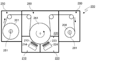
- FIG. 1 is a conceptual diagram of a configuration of a sputter deposition apparatus.
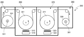
- 1 is a conceptual diagram of a configuration of a sputter deposition apparatus.
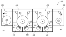
- 1 is a conceptual diagram of a configuration of a sputter deposition apparatus.
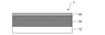
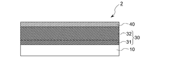
- It is typical sectional drawing showing the lamination structural example of a light control film.
- It is typical sectional drawing showing the lamination structural example of a light control film.
- FIG. 1 is a schematic cross-sectional view showing an example of a laminated structure of the light control film of the present invention.
- the light control film 1 includes a light control layer 30 and a catalyst layer 40 on a polymer film substrate 10.
- the polymer film substrate 10 may be transparent or opaque.
- a transparent plastic material is preferably used as the material of the polymer film substrate in order to make the light control film light transmissive during hydrogenation of the light control layer.
- the transparent plastic material include polyesters such as polyethylene terephthalate, cyclic polyolefins such as polyolefin and norbornene, polycarbonate, polyether sulfone, and polyarylate.
- the film thickness of the polymer film substrate 10 is not particularly limited, but is generally about 2 to 500 ⁇ m, preferably about 20 to 300 ⁇ m.
- An easy-adhesion layer, an antistatic layer, a hard coat layer, and the like may be provided on the surface of the polymer film substrate 10.
- the surface of the polymer film substrate 10 may be subjected to an appropriate adhesion treatment such as a corona discharge treatment, an ultraviolet irradiation treatment, a plasma treatment, or a sputter etching treatment from the viewpoint of improving the adhesion with the light control layer 30. .
- the thermal shrinkage rate in the longitudinal direction (MD: Machine Direction) of the polymer film substrate 10 is preferably 4% or less, more preferably 3% or less, and even more preferably 2% or less.
- MD Machine Direction
- the thermal contraction rate of the polymer film substrate is small, the dimensional change accompanying heating during the sputtering film formation or after the film formation is small, and the stress at the interface between the polymer film substrate 10 and the light control layer 30 can be reduced. . Therefore, the curvature of the film resulting from the stress of the interface and the film peeling of the light control layer can be suppressed, and the durability of the light control film can be improved.
- a light control film is obtained by sequentially forming the light control layer 30 and the catalyst layer 40 on the polymer film substrate 10 by sputtering.
- the material constituting the light control layer includes rare earth metals such as Y, La, Gd and Sm, alloys of rare earth metals and magnesium, alloys of alkaline earth metals such as Ca, Sr and Ba, magnesium, Ni, Examples include alloys of transition metals such as Mn, Co, and Fe with magnesium. Since the transparency at the time of hydrogenation is excellent, the light control layer 30 preferably contains magnesium. From the viewpoint of achieving both transparency and durability, an alloy of a rare earth metal element and magnesium is more preferable. In addition, the light control layer 30 may contain elements other than the said alloy as a trace component.
- Said metal or alloy which comprises the light control layer 30 contains the metal element which will be in a transparent state by hydrogenation, and will be in a reflective state by discharge
- magnesium becomes transparent MgH 2 when hydrogenated, and becomes Mg having metal reflection by dehydrogenation.
- the catalyst layer 40 on the light control layer 30 has a function of promoting hydrogenation and dehydrogenation of the light control layer 30.
- switching speed in switching from the reflective state to the transparent state (hydrogenation of the light control layer) and switching from the transparent state to the reflection state (dehydrogenation of the light control layer) is increased.
- the material of the catalyst layer 40 is not particularly limited as long as it has a function of promoting the hydrogenation and dehydrogenation of the light control layer 30.
- the catalyst layer 40 may be palladium, platinum, a palladium alloy, and a platinum alloy. It is preferred to have at least one metal selected.
- palladium is preferably used because of its high hydrogen permeability.
- film formation is performed using a roll-to-roll sputtering apparatus while continuously moving a long polymer film substrate in the longitudinal direction.
- the light control layer and the catalyst layer are formed using different sputtering targets.
- a roll-to-roll sputtering apparatus capable of mounting a plurality of targets along the film conveying direction in order to continuously form a light control layer and a catalyst layer without performing air release in the middle.
- Examples of the roll-to-roll sputtering apparatus capable of mounting a plurality of targets along the film conveying direction include those capable of arranging a plurality of targets around one film forming roll and those equipped with a plurality of film forming rolls. It is done.
- FIG. 2 is a conceptual diagram of a roll-to-roll sputtering apparatus configured to be capable of arranging a plurality of targets around one film forming roll.
- the sputtering apparatus 200 includes a preparation chamber 250, a film formation chamber 260, and a winding chamber 280, and a film formation roll 261 is provided in the film formation chamber 260.
- a plurality of sub film forming chambers 210 and 220 are provided along the circumferential direction of the film forming roll and separated by partition walls, and the cathodes 214 and 224 are provided in the respective sub film forming chambers. Is provided.
- Targets 213 and 223 are disposed on the cathodes 214 and 224 so as to face the film forming roll 261.
- FIG. 2 illustrates a form in which two sub film forming chambers are provided around one film forming roll, three or more sub film forming chambers are provided along the circumferential direction of the film forming roll. It may be.
- the film substrate unwound from the unwinding roll is conveyed onto the film forming roll 261 in the film forming chamber 260 and is sequentially guided to the first sub film forming chamber 210 and the second sub film forming chamber 220.
- a light control layer is formed on the film substrate in the first sub film formation chamber 210, and a catalyst layer is formed on the light control layer in the second sub film formation chamber 220.
- the light control film in which the light control layer and the catalyst layer are formed on the film substrate is guided to the winding chamber 280 and wound up by the winding roll 281 to obtain the wound body 208 of the light control film.
- the sputtering apparatus 200 may be configured to be able to transport a film from the roll 281 side to the roll 251 side by reversing the driving direction of each roll.
- the roll 201 of the film substrate is set on the roll 281, and the light control layer and the catalyst layer can be formed on the film formation roll 261 while the film is conveyed to the roll 251 side.
- the catalyst layer can be formed on the film forming roll 261 while being conveyed. As described above, when the light control layer and the catalyst layer are formed in two passes, the film formation conditions of the light control layer and the film formation conditions of the catalyst layer can be individually set. Even when the catalyst layer is formed without opening, the degree of freedom in setting the film formation conditions is increased.
- the substrate temperature at the time of sputtering film formation by the roll-to-roll sputtering apparatus is a set temperature of the film forming roll.
- the substrate temperature at the time of light control layer formation is the same as the substrate temperature at the time of catalyst layer formation.
- the substrate temperature at the time of forming the light control layer and the substrate temperature at the time of forming the catalyst layer can be individually set. If a plurality of targets are arranged in advance in the apparatus, the light control layer and the catalyst layer can be formed on the film substrate without opening to the atmosphere even when film formation is performed in two passes or three or more passes. Can be formed.
- FIG. 3 is a conceptual diagram of the configuration of a roll-to-roll sputtering apparatus including a plurality of film forming rolls.
- the sputtering apparatus 300 includes two film forming chambers 360 and 370 between a preparation chamber 350 and a winding chamber 380, and film forming rolls 361 and 371 and a cathode 314 are provided in the film forming chambers 360 and 370, respectively. , 324 are provided. Targets 313 and 323 are disposed on the cathodes 314 and 324 so as to face the film forming rolls 361 and 371.
- FIG. 3 illustrates a form including two film forming rolls
- the sputtering apparatus may include three or more film forming rolls.
- each film forming chamber may be provided with a plurality of sub film forming chambers separated by a partition around the film forming roll, and a cathode may be provided in each sub film forming chamber.
- the film substrate unwound from the unwinding roll 351 in the preparation chamber 350 is the first film forming roll in the first film forming chamber 360.
- the second film forming roll 371 of the second film forming chamber 370 After being transported onto the second film forming roll 371 of the second film forming chamber 370 and a catalyst layer is formed on the light control layer.
- the light control film in which the light control layer and the catalyst layer are formed on the film substrate is guided to the winding chamber 380 and wound up by the winding roll 381 to obtain the roll 308 of the light control film.
- the sputtering apparatus 300 may be configured to be able to transport a film from the roll 381 side to the roll 351 side by reversing the driving direction of each roll.
- the temperature of each film forming roll can be set individually. Therefore, even when the light control layer and the catalyst layer are formed in one pass, the substrate temperature at the time of forming the light control layer and the substrate temperature at the time of forming the catalyst layer can be individually set.
- the substrate temperature during film formation of the light control layer and the catalyst layer is not particularly limited, but is preferably ⁇ 20 ° C. to 180 ° C. from the viewpoint of suppressing embrittlement and thermal deformation of the film substrate.
- FIG. 4 is a conceptual diagram of a roll-to-roll sputtering apparatus configured to include a plurality of film forming rolls and to be able to arrange a plurality of targets around each film forming roll.
- the sputtering apparatus 400 includes two film forming chambers 460 and 470, and film forming rolls 461 and 471 are provided in the film forming chambers 460 and 470, respectively.
- a plurality of sub film forming chambers 410, 420, 430, 440 are provided along the circumferential direction of the film forming roll and separated by partition walls.
- cathodes 414, 424, 434, and 444 are provided in the room.
- Targets 413, 423, 433, and 443 are disposed on each cathode so as to face the film forming rolls 461 and 471, respectively.
- the first film formation chamber 460 and the second film formation chamber 460 are moved while being unwound from the unwinding roll 451 in the preparation chamber 450 and running.
- the film chamber 470 a light control layer and a catalyst layer are sequentially formed.
- the light control layer and the catalyst layer may be formed separately in the film thickness direction using a plurality of cathodes.
- the light control layer is formed into a film thickness by disposing the light control layer deposition targets 413 and 423 on the two cathodes 414 and 424 in the first film formation chamber, respectively.
- the film can be divided into two in the direction. After forming a part of the film thickness of the light control layer in the first film formation chamber 460, the remaining film thickness of the light control layer and the catalyst layer may be formed in the second film formation chamber 470.
- the light control layer and the catalyst layer may be formed in either the first film formation chamber or the second film formation chamber, and the base layer or the surface layer may be formed in the other film formation chamber.
- the base layer or the surface layer may be formed in the other film formation chamber.
- the sputtering apparatus In film formation of the light control layer and the catalyst layer by roll-to-roll sputtering, after the roll-shaped film substrate is loaded in the sputtering apparatus, the sputtering apparatus is evacuated before the start of film formation, moisture in the apparatus, It is preferable to have an atmosphere from which impurities such as moisture, oxygen and organic gas generated from the film substrate are removed. By removing the gas in the apparatus and in the film substrate in advance, it is possible to suppress oxidation due to incorporation of oxygen, moisture and the like into the light control layer 30.
- the amount (volume) of the substrate loaded in the vacuum chamber of the sputtering apparatus is larger than sputtering on glass or single wafer film.
- Moisture and the like are not easily degassed, and the amount of outgas from the substrate during sputtering film formation tends to increase.
- Moisture or the like from the substrate can oxidize the light control layer and cause a decrease in light control performance. Therefore, in the film formation of the light control layer by roll-to-roll sputtering, it is preferable that the pressure (degree of ultimate vacuum) in the sputtering apparatus before starting the sputtering film formation (before introducing the process gas) is as low as possible.
- the pressure in the apparatus before the start of sputtering film formation is, for example, 1 ⁇ 10 ⁇ 2 Pa or less, preferably 5 ⁇ 10 ⁇ 3 Pa or less, more preferably 1 ⁇ 10 ⁇ 3 Pa or less, and 5 ⁇ 10 ⁇ 4. Pa or less is more preferable, and 5 ⁇ 10 ⁇ 5 Pa or less is particularly preferable.
- the long film substrate may be transported in a vacuum chamber to degas the moisture in the film substrate.
- a metal target is used for forming the light control layer 30.
- an alloy target may be used, or a plurality of metal targets may be used.
- an alloy layer can also be formed using a target (divided target) in which a plurality of metal plates are arranged and bonded on a backing plate so that the erosion portion has a predetermined area ratio.
- a target divided target
- an alloy layer having a desired composition can be formed by adjusting the power applied to each target.
- the light control layer is formed while introducing an inert gas.
- the oxidized region 31 formed at the initial stage of the light control layer 30 has an action of blocking outgas from the film substrate 10. That is, the oxidation region 31 on the interface side of the light control layer 30 with the film substrate 10 functions as a sacrificial layer, thereby suppressing oxidation of the light control region 32 located on the catalyst layer 40 side and maintaining high light control performance. it can. Therefore, when forming a light control layer in contact with the film substrate 10, the film substrate 10 side has an oxidized region 31 having an oxygen content of 50 atomic% or more, and the oxygen content is 50 atomic% thereon. It is preferable that the light control layer 30 which has the light control area
- the thickness of the oxidized region 31 is preferably 2 nm or more.
- the thickness of the oxidized region is preferably 100 nm or less.
- the thickness of the oxidized region is more preferably 4 to 80 nm, and further preferably 6 to 60 nm.
- the oxygen content near the interface of the light control layer 30 on the catalyst layer 40 side is as small as possible.
- the oxygen content within a range of 5 nm from the interface on the catalyst layer 40 side of the light control layer 30 is preferably less than 50 atomic%, more preferably 45 atomic% or less, and even more preferably 40 atomic% or less.
- the oxygen content in the light control layer 30 is determined by X-ray electron spectroscopy (XPS) while etching the light control layer from the surface side (catalyst layer 40 side) to the substrate side of the light control film. It is obtained by measuring the directional distribution (depth profile). The etching depth (nm) in the depth profile is calculated by multiplying the etching time (min) by the standard etching rate (nm / min) for SiO 2 . In the obtained depth profile, it is located between the layer adjacent to the light control layer and the light control layer, and the position where the concentration of the element most contained in the layer adjacent to the light control layer is half the maximum value is set.
- XPS X-ray electron spectroscopy
- the thickness of the light control region 32 and the oxygen content from the start point of the light control layer to the point where the oxygen content is 50 atomic% or more are defined as the interface between the light control layer and the adjacent layer (start point and end point of the light control layer)
- the thickness of the region where is 50 atomic% or more is defined as the thickness of the oxidized region 31.
- the film thickness of the light control layer 30 is not particularly limited, but is preferably 10 nm to 500 nm, more preferably 15 nm to 200 nm, from the viewpoint of achieving both the light transmittance in the transparent state and the light shielding rate (reflectance) in the reflective state. 20 nm to 100 m is more preferable. If the film thickness of the light control layer is excessively small, the light reflectance in the reflective state tends to be low, and if the film thickness of the light control layer is excessively large, the light transmittance in the transparent state tends to be low. As shown in FIG.
- the oxidation region 31 having an oxygen content of 50 atomic% or more when the oxidation region 31 having an oxygen content of 50 atomic% or more is formed in the vicinity of the substrate 10 side interface of the light control layer 30, the light control region 32 having an oxygen content of less than 50 atomic%.
- the catalyst layer is formed without opening to the atmosphere.
- a metal target is used for forming the catalyst layer.
- the catalyst layer is formed while introducing an inert gas.
- the film thickness of the catalyst layer can be appropriately set depending on the reactivity of the light control layer, the catalyst ability of the catalyst layer, and the like, and is not particularly limited, but is preferably 1 to 30 nm, and more preferably 2 to 20 nm. If the film thickness of the catalyst layer is excessively small, the catalytic functions of hydrogenation and dehydrogenation may not be sufficiently exhibited. If the film thickness of the catalyst layer is excessively large, the light transmittance tends to decrease.
- an oxidation region may be formed at the substrate 10 side interface of the light control layer 30.
- the oxide film prevents hydrogen from moving between the catalyst layer and the light control layer.
- magnesium since magnesium has a high bonding force with oxygen, when the catalyst layer side interface of the light control layer composed mainly of magnesium is oxidized, the light control layer is hydrogenated even if hydrogen is introduced from the catalyst layer side. Otherwise, the dimming performance cannot be demonstrated.
- the film formation surface of the light control layer is not exposed to the atmosphere by forming the catalyst layer without opening to the atmosphere after the light control layer is formed. Oxidation at the interface on the layer 40 side can be suppressed. Therefore, even when the light control layer is made of a material mainly composed of a metal having a strong binding force with oxygen such as magnesium, the oxygen content in the vicinity of the interface on the catalyst layer 40 side of the light control layer 30 is within the above range.
- the light control film which can switch between a transparent state and a reflective state by hydrogenation and dehydrogenation of a light control layer can be obtained.
- the process from film formation of the light control layer to film formation of the catalyst layer can be continued without opening to the atmosphere. Can be implemented.
- the catalyst layer may be formed while the film is run again.
- the light control layer can be formed without winding up the film substrate after the light control layer is formed.
- the catalyst layer may be formed in one pass. As shown in FIG. 3 and FIG. 4, if the sputtering device having a plurality of film-forming rolls is used and the film-forming layer and the catalyst layer are formed on different film-forming rolls, The catalyst layer and the catalyst layer can be formed in one pass at different substrate temperatures.
- contact between the light control layer and the film substrate may increase the oxygen content at the catalyst layer side interface of the light control layer.
- a film substrate made of an oxygen atom-containing polymer such as polyester is used, or a film having a hard coat layer containing oxygen atoms such as acrylic or epoxy on the back surface (the surface opposite to the light-control layer forming surface)
- the film formation surface is easily oxidized by contact between the back surface of the film substrate and the film formation surface of the light control layer.
- the catalyst layer is formed on the light control layer without bringing the film formation surface of the light control layer into contact with the back surface of the film substrate. Further, in the one-pass film formation, the time until the catalyst layer is formed on the light control layer after the film formation is short, and the light control layer is oxidized due to outgas from the substrate in the sputtering apparatus. Can be suppressed. Therefore, further suppression of oxidation at the catalyst layer side interface of the light control layer can be expected by forming the light control layer and the catalyst layer in one pass.
- the amount of outgas from the film substrate tends to be larger than that on glass or a single-wafer film, and the light control layer has a strong binding force with oxygen such as magnesium.
- the light control layer after film formation on the substrate may be oxidized by the outgas (oxidizing gas) from the film substrate in the vacuum chamber even when the atmosphere is not opened. Therefore, it is preferable to form a film having higher oxidation resistance than the light control layer on the light control layer in a short time after the light control layer is formed.
- Specific examples of the film having higher oxidation resistance than that of the light control layer include a catalyst layer, a buffer layer and a surface layer, which will be described later.
- the time from the formation of the light control layer to the formation of a highly oxidation-resistant film such as a catalyst layer thereon is preferably within 60 minutes, more preferably within 45 minutes, even more preferably within 30 minutes, Within 10 minutes is particularly preferred.
- the catalyst layer is formed while the film is run again after the film substrate after the light control layer is formed, the time until the film travel is resumed after the film substrate is wound up. It is preferable to shorten it.
- the portion where the light control layer is first formed (the substrate at the start of film formation) It is preferable to adjust the total length of the film substrate so that the time until the catalyst layer is formed on the outer peripheral portion of the wound body is within 60 minutes.
- the time until the catalyst layer is formed after the light control layer is formed is uniform along the longitudinal direction of the film substrate.
- the total length of the film substrate is not limited, and the productivity of the light control film by roll-to-roll can be improved.
- the lower limit of the time from the formation of the light control layer to the formation of the catalyst layer and the like is not particularly limited, but is generally 0.1 seconds or longer.
- the film substrate transport speed when the light control layer and the catalyst layer are formed by roll-to-roll sputtering is, for example, 0.5 m / min or more, preferably 1 m / min or more, and more preferably 2 m / min. More than a minute.
- the upper limit of the transport speed of the film substrate is not particularly limited as long as the transportability can be maintained, and is generally 100 m / min or less.
- the light control film of the present invention may have a layer other than the light control layer 30 and the catalyst layer 40 on the polymer film substrate 10.
- the base layer 20 may be provided between the film substrate 10 and the light control layer 30, or the buffer layer 50 may be provided between the light control layer 30 and the catalyst layer 40.
- the surface layer 70 may be provided on the catalyst layer.
- the inorganic oxide examples include Si, Ge, Sn, Pb, Al, Ga, In, Tl, As, Sb, Bi, Se, Te, Mg, Ca, Sr, Ba, Sc, Y, Ti, Zr, Metals such as Hf, V, Nb, Ta, Cr, Mo, W, Mn, Tc, Re, Fe, Ru, Os, Co, Rh, Ir, Ni, Pd, Pt, Cu, Ag, Au, Zn, Cd
- An oxide of an element or a metalloid element is preferably used.
- the inorganic oxide layer may contain a mixed oxide of a plurality of (semi) metals. Among these, oxides such as Si, Nb, and Ti are preferably used because they have low light absorption and excellent gas barrier properties such as oxygen and water vapor.
- the thickness of the underlayer 20 is preferably 1 nm or more.
- the film thickness of the underlayer is preferably 200 nm or less. .
- the underlayer 20 has a barrier property against the gas from the film substrate, formation of an oxidized region at the initial stage of film formation of the light control layer is suppressed.
- the outgas from the film substrate 10 is blocked by the underlayer 20, so that the light control layer 30 is oxidized due to the outgas from the film substrate. Suppressing and maintaining high dimming performance.
- an underlayer may be provided by a sputtering method.
- a metal target or an oxide target is used.
- sputter film formation is performed while introducing a reactive gas (for example, oxygen) in addition to an inert gas such as argon.
- a reactive gas for example, oxygen
- an oxide target is used, film formation is performed while introducing an inert gas such as argon. Even when an oxide target is used, film formation may be performed while introducing a reactive gas as necessary.
- the buffer layer 50 is preferably one that can transmit hydrogen.
- the buffer layer may be composed of only one layer, and may include a plurality of layers.
- the buffer layer 50 may have a stacked structure of a layer having a function of suppressing metal migration from the light control layer 30 and a layer that suppresses transmission of oxygen from the catalyst layer 40 side to the light control layer 30.
- the buffer layer 50 By providing a metal thin film made of W, Ta, Hf or an alloy of these metals as the buffer layer 50, the permeation of oxygen from the catalyst layer 40 side to the light control layer 30 is suppressed, and the light control layer is oxidized. Deterioration due to can be suppressed. Further, by inserting a metal thin film containing the same metal as the light control layer as the buffer layer 50, the buffer layer 50 can function as a sacrificial layer that reacts with oxygen that passes through the catalyst layer 40, and the oxidation of the light control layer 30 can be suppressed.
- Such a buffer layer acting as a sacrificial layer is preferably reversibly bonded to oxygen, and is hydrogenated when the light control layer 30 is hydrogenated (transparent state), so that the light transmittance is preferably increased.
- the magnesium content relative to the total amount of metal elements is preferably less than 50 atomic%.
- Formation of the buffer layer 50 on the light control layer 30 is performed by roll-to-roll sputtering.
- the buffer layer 50 and the catalyst layer 40 are continuously formed without opening to the atmosphere after the light control layer 30 is formed.
- the film thickness of the buffer layer 50 can be set as appropriate according to the purpose and the like, and is not particularly limited.
- the surface layer 70 When the surface layer 70 is provided on the catalyst layer 40, the surface layer 70 only needs to be capable of permeating hydrogen.
- the surface layer 70 preferably has a function of blocking the permeation of water and oxygen and preventing the light control layer 30 from being oxidized. Moreover, by adjusting the optical film thickness of the surface layer 70, the light reflection in the surface of a light control film can be reduced, and the light transmittance in a transparent state can be improved.
- the (semi) metal oxide exemplified above as the material of the inorganic oxide layer constituting the base layer, the metal exemplified as the material of the buffer layer, or the like can be used.
- an organic material such as a polymer, an organic-inorganic hybrid material, or the like can be used. If a material having water repellency such as a fluorine-based resin is used as the material of the surface layer 70, the function of suppressing the oxidation of the light control layer 30 by water or oxygen can be further enhanced, and the durability of the light control element can be improved.
- the film thickness of the surface layer 70 can be appropriately set according to the purpose and the like, and is not particularly limited, but is, for example, about 1 nm to 50 ⁇ m.
- the surface layer may be composed of only one layer, and may include a plurality of layers. For example, by stacking a plurality of thin films having different refractive indexes and adjusting the optical film thickness of each layer, the antireflection performance can be improved and the light transmittance in a transparent state can be increased. Further, durability can be improved by combining an organic layer and an inorganic layer.
- the formation method of the surface layer 70 is not particularly limited.
- the surface layer may be formed by roll-to-roll sputtering, or the surface layer may be formed after releasing the atmosphere after forming the catalyst layer.
- the method for forming the surface layer is not limited to sputtering.
- the film is preferably formed by a wet method such as spin coating, dip coating, gravure coating, or die coating.
- a wet method such as the above-described coating method, CBD method, or plating method may be employed, and other than sputtering methods such as vacuum evaporation method, electron beam evaporation method, CVD method, etc.
- a dry process can also be employed.
- the light control film of this invention can be used for the hydrogen active type light control element which can switch the permeation
- the method for hydrogenating and dehydrogenating the light control layer is not particularly limited.
- the light control film is exposed to a hydrogen atmosphere to hydrogenate the light control layer, and the light control film is exposed to an oxygen atmosphere (air).
- a method for dehydrogenating the light control layer gas chromic method
- the gaschromic method is preferable because a large-area light control layer can be switched in a short time.
- the light control film of the present invention may be used as a light control element as it is, or may be formed in combination with a transparent member such as glass, a translucent member, an opaque member, or the like.
- a gas chromic light control element By arranging the light control film of the present invention in a gas filling chamber, a gas chromic light control element can also be formed.
- a gas chromic light control element the structure which has arrange
- This light control element can reversibly switch between the transparent state and the reflective state by hydrogenating and dehydrogenating the light control layer by supplying and exhausting hydrogen into the gas filling chamber.
- the volume of the light control layer changes due to hydrogenation and dehydrogenation, and stress is generated at the film interface accordingly.
- the film may be warped or peeled off due to the stress at the film interface of the light control layer on the film substrate side.
- the stress at the interface is relieved, and the light control film warps and Film peeling can be suppressed.
- the light control element using the light control film of the present invention can be applied to a window glass of a building or a vehicle, a shielding object for the purpose of privacy protection, various decorations, a lighting device, an entertainment tool, and the like. Since the light control film of the present invention uses a flexible substrate, it is easy to process and can be applied to a curved surface.
- Example 1 In Example 1, using a roll-to-roll sputtering apparatus having two film forming chambers, a first film forming chamber having a first film forming roll and a second film forming chamber having a second film forming roll, a transparent film substrate is used. On top, an Mg—Y light control layer and a Pd catalyst layer were formed. The Mg—Y target was placed so as to face the first film forming roll of the sputtering apparatus, and the Pd target was placed so as to face the second film forming roll. As the Mg—Y target, an Mg—Y split target (manufactured by Rare Metallic) having an Mg metal plate and a Y metal plate with an area ratio of 2: 5 in the erosion portion was used. A Pd metal target (manufactured by Tanaka Kikinzoku Co., Ltd.) was used as the Pd target.
- Mg—Y split target manufactured by Rare Metallic
- PET film having a thickness of 188 ⁇ m (manufactured by Mitsubishi Plastics, MD with 2% thermal shrinkage) is set on the unwinding roll of the sputtering apparatus, and the ultimate vacuum in each film forming chamber is 5 ⁇ 10 ⁇ It exhausted until it became 3 Pa.
- the pressure in the first film formation chamber increased to 4 ⁇ 10 ⁇ 2 Pa due to the release of the residual gas contained in the PET film.
- Argon was introduced into each film forming chamber in the sputtering apparatus so that the process pressure was 0.4 Pa, the PET film was unwound from the unwinding roll, and the apparatus was run at 3 m / min.
- a light control layer (film thickness: 43 nm) made of Mg—Y alloy is continuously formed on the first film forming roll, and a catalyst layer (film thickness: 10 nm) made of Pd is continuously formed on the second film forming roll.
- the PET film was wound up.
- the substrate temperature at the time of film formation of the light control layer and the catalyst layer are both -5 ° C. After the light control layer is formed, the catalyst is formed on the light control layer
- the time (interval) required to form the layer was 5 minutes.
- Example 2 and Example 3 In Example 2 and Example 3, the same roll-to-roll sputtering apparatus as in Example 1 was used, and the Pd target was faced to the first film-forming roll, and the Mg—Y was faced to face the second film-forming roll. A target was placed, and an Mg—Y light control layer and a Pd catalyst layer were formed on the transparent film substrate. did.
- a PET film roll having a thickness of 188 ⁇ m is set on the unwinding roll of the sputtering apparatus, the PET film is unwound from the unwinding roll and travels through the apparatus at 1 m / min, and discharge from the cathode facing the first film-forming roll.
- a light control layer made of an Mg—Y alloy was formed on the second film forming roll by DC sputtering, and the film was wound up by a winding roll.
- the discharge from the cathode facing the second film-forming roll is turned off, the discharge from the cathode facing the first film-forming roll is started, and the film is fed from the winding roll.
- a catalyst layer composed of a Pd layer was formed on the first film-forming roll by DC sputtering, and the film was wound up by a feeding roll.
- the substrate temperature during film formation of the light control layer and the catalyst layer was both -5 ° C. Two different points in the longitudinal direction of the film base material were sampled to be Example 2 and Example 3, respectively.
- the interval between the light control layer formation and the catalyst layer formation was 25 minutes for Example 2 and 60 minutes for Example 3.
- Comparative Example 1 In Comparative Example 1, the same roll-to-roll sputtering apparatus as in Example 1 was used, and the Mg—Y light control layer and the Pd catalyst layer were formed on the PET film using only the first film formation chamber. The Mg—Y target was placed so as to face the first film forming roll of the sputtering apparatus, and the target was not placed at the position facing the second film forming roll.
- a PET film roll having a thickness of 188 ⁇ m was set on the unwinding roll of the sputtering apparatus, and the PET film was unwound from the unwinding roll and run in the apparatus under the same conditions as in Example 1. Then, a light control layer made of an Mg—Y alloy was formed by DC sputtering, and the film was wound up by a take-up roll without forming a film on the second film-forming roll.
- the vacuum is broken to release the atmosphere, and the target placed facing the first film-forming roll with the inside of the sputtering apparatus at normal pressure is used as the Mg—Y target.
- the Pd layer is formed by DC sputtering on the first film-forming roll while the PET film on which the Mg—Y layer is formed is fed from the side of the take-up roll and running in the apparatus, and the film is formed by the feed roll. Winded up.
- the substrate temperature during formation of the light control layer and the catalyst layer was ⁇ 5 ° C., and the interval between the light control layer formation and the catalyst layer formation was 180 minutes (including the air release time).
Landscapes
- Physics & Mathematics (AREA)
- Nonlinear Science (AREA)
- General Physics & Mathematics (AREA)
- Optics & Photonics (AREA)
- Electrochromic Elements, Electrophoresis, Or Variable Reflection Or Absorption Elements (AREA)
- Physical Vapour Deposition (AREA)
Abstract
Priority Applications (3)
| Application Number | Priority Date | Filing Date | Title |
|---|---|---|---|
| EP17770325.3A EP3435151A4 (fr) | 2016-03-25 | 2017-03-23 | Procédé de production de film de modulation de lumière |
| KR1020187025067A KR20180122340A (ko) | 2016-03-25 | 2017-03-23 | 조광 필름의 제조 방법 |
| CN201780019696.4A CN108885380A (zh) | 2016-03-25 | 2017-03-23 | 调光薄膜的制造方法 |
Applications Claiming Priority (4)
| Application Number | Priority Date | Filing Date | Title |
|---|---|---|---|
| JP2016-062620 | 2016-03-25 | ||
| JP2016062620 | 2016-03-25 | ||
| JP2017-056183 | 2017-03-22 | ||
| JP2017056183A JP2017182062A (ja) | 2016-03-25 | 2017-03-22 | 調光フィルムの製造方法 |
Publications (1)
| Publication Number | Publication Date |
|---|---|
| WO2017164285A1 true WO2017164285A1 (fr) | 2017-09-28 |
Family
ID=59900285
Family Applications (1)
| Application Number | Title | Priority Date | Filing Date |
|---|---|---|---|
| PCT/JP2017/011643 Ceased WO2017164285A1 (fr) | 2016-03-25 | 2017-03-23 | Procédé de production de film de modulation de lumière |
Country Status (1)
| Country | Link |
|---|---|
| WO (1) | WO2017164285A1 (fr) |
Citations (4)
| Publication number | Priority date | Publication date | Assignee | Title |
|---|---|---|---|---|
| JP2013083911A (ja) | 2011-09-30 | 2013-05-09 | National Institute Of Advanced Industrial & Technology | 反射型調光素子、該反射型調光素子を用いた反射型調光部材、及び、複層ガラス。 |
| JP2014026262A (ja) | 2012-06-20 | 2014-02-06 | National Institute Of Advanced Industrial & Technology | 反射型調光素子。 |
| JP2014134676A (ja) * | 2013-01-10 | 2014-07-24 | National Institute Of Advanced Industrial & Technology | ガスクロミック調光部材。 |
| US20150198856A1 (en) * | 2014-01-15 | 2015-07-16 | Samsung Electronics Co., Ltd. | Electrochromic device |
-
2017
- 2017-03-23 WO PCT/JP2017/011643 patent/WO2017164285A1/fr not_active Ceased
Patent Citations (4)
| Publication number | Priority date | Publication date | Assignee | Title |
|---|---|---|---|---|
| JP2013083911A (ja) | 2011-09-30 | 2013-05-09 | National Institute Of Advanced Industrial & Technology | 反射型調光素子、該反射型調光素子を用いた反射型調光部材、及び、複層ガラス。 |
| JP2014026262A (ja) | 2012-06-20 | 2014-02-06 | National Institute Of Advanced Industrial & Technology | 反射型調光素子。 |
| JP2014134676A (ja) * | 2013-01-10 | 2014-07-24 | National Institute Of Advanced Industrial & Technology | ガスクロミック調光部材。 |
| US20150198856A1 (en) * | 2014-01-15 | 2015-07-16 | Samsung Electronics Co., Ltd. | Electrochromic device |
Non-Patent Citations (2)
| Title |
|---|
| KAZUKI YOSHIMURA: "Switchable Mirror Window -Technology ni yori Kaiteki na Sho-energy Juseikatsu Kukan o Motomeru = [Dimmable mirror glass window-seeking a comfortable energy saving living space by technology]", NANOTECH JAPAN BULLETIN, vol. 6, no. 4, 30 August 2013 (2013-08-30), pages 1 - 11, XP009514612 * |
| See also references of EP3435151A4 |
Similar Documents
| Publication | Publication Date | Title |
|---|---|---|
| CN107615157B (zh) | 调光薄膜及其制造方法、以及调光元件 | |
| JP2017182062A (ja) | 調光フィルムの製造方法 | |
| US10514560B2 (en) | Light-modulating film and method for producing same, and light-modulating element | |
| WO2019176969A1 (fr) | Élément de commande de lumière par gaz chromique | |
| WO2016186130A1 (fr) | Film de modulation de lumière et son procédé de fabrication ainsi qu'élément de modulation de lumière | |
| CN104412154A (zh) | 反射型调光元件 | |
| TWI617459B (zh) | 氣體障壁性薄膜及其製造方法 | |
| JPWO2016190284A6 (ja) | ガスバリア性フィルムおよびその製造方法 | |
| WO2017164285A1 (fr) | Procédé de production de film de modulation de lumière | |
| WO2016186131A1 (fr) | Film de modulation de lumière et son procédé de production, et élément de modulation de lumière | |
| JP4325310B2 (ja) | 導電性光反射膜の形成方法 | |
| US20220066273A1 (en) | Light control film and manufacturing method thereof | |
| JP2018012234A (ja) | ガスバリアー性フィルム及び電子デバイス | |
| TW201730009A (zh) | 氣體阻障性薄膜及具備此之電子裝置 | |
| KR101719520B1 (ko) | 탄화불소 박막을 포함하는 다층 배리어 필름 및 이의 제조방법 | |
| JP2020142441A (ja) | 機能性フィルムおよびその製造方法 | |
| WO2017090605A1 (fr) | Film doté de propriétés de barrière contre les gaz et dispositif électronique | |
| JP2024123911A (ja) | 積層体、積層体の製造方法、フレキシブルデバイス、太陽電池、および光学センサ | |
| CN111933721A (zh) | 太阳能电池组件的前板及制备方法和柔性太阳能电池组件 | |
| JP2019010734A (ja) | 積層型ガスバリアー性フィルム及び電子デバイス | |
| WO2017163577A1 (fr) | Procédé de fabrication de stratifié |
Legal Events
| Date | Code | Title | Description |
|---|---|---|---|
| ENP | Entry into the national phase |
Ref document number: 20187025067 Country of ref document: KR Kind code of ref document: A |
|
| NENP | Non-entry into the national phase |
Ref country code: DE |
|
| WWE | Wipo information: entry into national phase |
Ref document number: 2017770325 Country of ref document: EP |
|
| ENP | Entry into the national phase |
Ref document number: 2017770325 Country of ref document: EP Effective date: 20181025 |
|
| 121 | Ep: the epo has been informed by wipo that ep was designated in this application |
Ref document number: 17770325 Country of ref document: EP Kind code of ref document: A1 |