WO2017164326A1 - Appareil de refroidissement, procédé de commande et support de stockage - Google Patents
Appareil de refroidissement, procédé de commande et support de stockage Download PDFInfo
- Publication number
- WO2017164326A1 WO2017164326A1 PCT/JP2017/011790 JP2017011790W WO2017164326A1 WO 2017164326 A1 WO2017164326 A1 WO 2017164326A1 JP 2017011790 W JP2017011790 W JP 2017011790W WO 2017164326 A1 WO2017164326 A1 WO 2017164326A1
- Authority
- WO
- WIPO (PCT)
- Prior art keywords
- refrigerator
- blower
- electronic device
- temperature
- refrigerant
- Prior art date
- Legal status (The legal status is an assumption and is not a legal conclusion. Google has not performed a legal analysis and makes no representation as to the accuracy of the status listed.)
- Ceased
Links
Images







Classifications
-
- G—PHYSICS
- G06—COMPUTING OR CALCULATING; COUNTING
- G06F—ELECTRIC DIGITAL DATA PROCESSING
- G06F1/00—Details not covered by groups G06F3/00 - G06F13/00 and G06F21/00
- G06F1/16—Constructional details or arrangements
- G06F1/20—Cooling means
- G06F1/206—Cooling means comprising thermal management
-
- F—MECHANICAL ENGINEERING; LIGHTING; HEATING; WEAPONS; BLASTING
- F24—HEATING; RANGES; VENTILATING
- F24F—AIR-CONDITIONING; AIR-HUMIDIFICATION; VENTILATION; USE OF AIR CURRENTS FOR SCREENING
- F24F11/00—Control or safety arrangements
- F24F11/70—Control systems characterised by their outputs; Constructional details thereof
- F24F11/72—Control systems characterised by their outputs; Constructional details thereof for controlling the supply of treated air, e.g. its pressure
- F24F11/74—Control systems characterised by their outputs; Constructional details thereof for controlling the supply of treated air, e.g. its pressure for controlling air flow rate or air velocity
-
- F—MECHANICAL ENGINEERING; LIGHTING; HEATING; WEAPONS; BLASTING
- F24—HEATING; RANGES; VENTILATING
- F24F—AIR-CONDITIONING; AIR-HUMIDIFICATION; VENTILATION; USE OF AIR CURRENTS FOR SCREENING
- F24F11/00—Control or safety arrangements
- F24F11/89—Arrangement or mounting of control or safety devices
-
- F—MECHANICAL ENGINEERING; LIGHTING; HEATING; WEAPONS; BLASTING
- F25—REFRIGERATION OR COOLING; COMBINED HEATING AND REFRIGERATION SYSTEMS; HEAT PUMP SYSTEMS; MANUFACTURE OR STORAGE OF ICE; LIQUEFACTION SOLIDIFICATION OF GASES
- F25B—REFRIGERATION MACHINES, PLANTS OR SYSTEMS; COMBINED HEATING AND REFRIGERATION SYSTEMS; HEAT PUMP SYSTEMS
- F25B1/00—Compression machines, plants or systems with non-reversible cycle
-
- G—PHYSICS
- G06—COMPUTING OR CALCULATING; COUNTING
- G06F—ELECTRIC DIGITAL DATA PROCESSING
- G06F1/00—Details not covered by groups G06F3/00 - G06F13/00 and G06F21/00
- G06F1/16—Constructional details or arrangements
- G06F1/20—Cooling means
-
- H—ELECTRICITY
- H05—ELECTRIC TECHNIQUES NOT OTHERWISE PROVIDED FOR
- H05K—PRINTED CIRCUITS; CASINGS OR CONSTRUCTIONAL DETAILS OF ELECTRIC APPARATUS; MANUFACTURE OF ASSEMBLAGES OF ELECTRICAL COMPONENTS
- H05K7/00—Constructional details common to different types of electric apparatus
- H05K7/20—Modifications to facilitate cooling, ventilating, or heating
- H05K7/2029—Modifications to facilitate cooling, ventilating, or heating using a liquid coolant with phase change in electronic enclosures
- H05K7/20381—Thermal management, e.g. evaporation control
-
- H—ELECTRICITY
- H05—ELECTRIC TECHNIQUES NOT OTHERWISE PROVIDED FOR
- H05K—PRINTED CIRCUITS; CASINGS OR CONSTRUCTIONAL DETAILS OF ELECTRIC APPARATUS; MANUFACTURE OF ASSEMBLAGES OF ELECTRICAL COMPONENTS
- H05K7/00—Constructional details common to different types of electric apparatus
- H05K7/20—Modifications to facilitate cooling, ventilating, or heating
- H05K7/20709—Modifications to facilitate cooling, ventilating, or heating for server racks or cabinets; for data centers, e.g. 19-inch computer racks
- H05K7/208—Liquid cooling with phase change
- H05K7/20827—Liquid cooling with phase change within rooms for removing heat from cabinets, e.g. air conditioning devices
-
- H—ELECTRICITY
- H05—ELECTRIC TECHNIQUES NOT OTHERWISE PROVIDED FOR
- H05K—PRINTED CIRCUITS; CASINGS OR CONSTRUCTIONAL DETAILS OF ELECTRIC APPARATUS; MANUFACTURE OF ASSEMBLAGES OF ELECTRICAL COMPONENTS
- H05K7/00—Constructional details common to different types of electric apparatus
- H05K7/20—Modifications to facilitate cooling, ventilating, or heating
- H05K7/20709—Modifications to facilitate cooling, ventilating, or heating for server racks or cabinets; for data centers, e.g. 19-inch computer racks
- H05K7/20836—Thermal management, e.g. server temperature control
-
- F—MECHANICAL ENGINEERING; LIGHTING; HEATING; WEAPONS; BLASTING
- F24—HEATING; RANGES; VENTILATING
- F24F—AIR-CONDITIONING; AIR-HUMIDIFICATION; VENTILATION; USE OF AIR CURRENTS FOR SCREENING
- F24F11/00—Control or safety arrangements
- F24F11/30—Control or safety arrangements for purposes related to the operation of the system, e.g. for safety or monitoring
- F24F11/46—Improving electric energy efficiency or saving
-
- F—MECHANICAL ENGINEERING; LIGHTING; HEATING; WEAPONS; BLASTING
- F25—REFRIGERATION OR COOLING; COMBINED HEATING AND REFRIGERATION SYSTEMS; HEAT PUMP SYSTEMS; MANUFACTURE OR STORAGE OF ICE; LIQUEFACTION SOLIDIFICATION OF GASES
- F25B—REFRIGERATION MACHINES, PLANTS OR SYSTEMS; COMBINED HEATING AND REFRIGERATION SYSTEMS; HEAT PUMP SYSTEMS
- F25B49/00—Arrangement or mounting of control or safety devices
-
- Y—GENERAL TAGGING OF NEW TECHNOLOGICAL DEVELOPMENTS; GENERAL TAGGING OF CROSS-SECTIONAL TECHNOLOGIES SPANNING OVER SEVERAL SECTIONS OF THE IPC; TECHNICAL SUBJECTS COVERED BY FORMER USPC CROSS-REFERENCE ART COLLECTIONS [XRACs] AND DIGESTS
- Y02—TECHNOLOGIES OR APPLICATIONS FOR MITIGATION OR ADAPTATION AGAINST CLIMATE CHANGE
- Y02B—CLIMATE CHANGE MITIGATION TECHNOLOGIES RELATED TO BUILDINGS, e.g. HOUSING, HOUSE APPLIANCES OR RELATED END-USER APPLICATIONS
- Y02B30/00—Energy efficient heating, ventilation or air conditioning [HVAC]
- Y02B30/70—Efficient control or regulation technologies, e.g. for control of refrigerant flow, motor or heating
-
- Y—GENERAL TAGGING OF NEW TECHNOLOGICAL DEVELOPMENTS; GENERAL TAGGING OF CROSS-SECTIONAL TECHNOLOGIES SPANNING OVER SEVERAL SECTIONS OF THE IPC; TECHNICAL SUBJECTS COVERED BY FORMER USPC CROSS-REFERENCE ART COLLECTIONS [XRACs] AND DIGESTS
- Y02—TECHNOLOGIES OR APPLICATIONS FOR MITIGATION OR ADAPTATION AGAINST CLIMATE CHANGE
- Y02D—CLIMATE CHANGE MITIGATION TECHNOLOGIES IN INFORMATION AND COMMUNICATION TECHNOLOGIES [ICT], I.E. INFORMATION AND COMMUNICATION TECHNOLOGIES AIMING AT THE REDUCTION OF THEIR OWN ENERGY USE
- Y02D10/00—Energy efficient computing, e.g. low power processors, power management or thermal management
Definitions
- the present invention relates to a cooling device or the like, for example, a cooling device or the like for cooling an electronic device.
- Electric devices such as servers and network devices in data centers installed in each region include, for example, heat generation components such as a central processing unit (CPU: Central Processing Unit) and an integrated circuit (LSI: Large Scale Integration). Contained. These heat generating parts generate heat. For this reason, in the data center, the electronic device is cooled using, for example, an air conditioner.
- CPU Central Processing Unit
- LSI Large Scale Integration
- Patent Document 1 discloses a technique for reducing the power consumption of an air conditioner as an outside air heat exchange system.
- the outdoor air heat exchange system includes an air-cooled heat exchanger 11, a heat exchanger 12, a pump 13, and a control device 30.
- the air cooling heat exchanger 11 is a heat exchanger installed outdoors.
- the heat exchanger 12 is a heat exchanger installed indoors.
- the air-cooled heat exchanger 11 includes a heat exchanger body 11a, a fan 11b (air conditioner), and the like.
- the thermometer 21 measures the intake air temperature of the air-cooled heat exchanger 11.
- the thermometer 22 measures the exhaust temperature of the air-cooled heat exchanger 11.
- the wattmeter 23 measures the power consumed by the pump 13.
- the power meter 24 of the fan 11b measures the power consumption of the fan 11b.
- the control device 30 controls the rotation speed of the fan 11b.
- control device 30 calculates the heat exchange amount of the air-cooling heat exchanger 11 based on the temperature difference between the intake air temperature and the exhaust temperature of the air-cooling heat exchanger 11 and the fan air volume calculated from the rotational speed of the fan 11b. To do.
- the control device 30 calculates a coefficient of performance (COP: Coefficient ⁇ of Performance) based on the calculated value of the heat exchange amount and the power consumption of the pump 13 and the fan 11b.
- the coefficient of performance is an index representing the cooling capacity per unit power consumption. Further, the control device 30 increases or decreases the rotational speed of the fan 11b so as to improve the calculated coefficient of performance.
- the outside air heat exchange system calculates a coefficient of performance (COP) based on the amount of heat exchange with the outside air and power consumption in the outside air heat exchange system,
- the fan rotation speed of the outside air heat exchange system is controlled based on the coefficient (COP).
- COP coefficient of performance
- the outside air heat exchange system stops. As a result, it is possible to operate at maximum efficiency in various outside air conditions, thereby saving energy.
- control device 30 calculates the COP using the temperature difference between the intake air temperature and the exhaust gas temperature of the fan 11b of the air-cooled heat exchanger 11.
- the temperature difference between the intake air temperature and the exhaust gas temperature of the air-cooled heat exchanger 11 may vary greatly depending on the installation location of the thermometer 21 and the thermometer 22 of the air-cooled heat exchanger 11. Since the wind power fluctuation is particularly large on the exhaust side of the fan 11b, if a thermometer 22 for measuring the exhaust temperature of the air-cooling heat exchanger 11 is arranged in the vicinity of the fan 11b as in the technique described in Patent Document 1, the air-cooling heat exchanger Thus, the temperature difference between the intake air temperature and the exhaust gas temperature varies greatly. As a result, the COP calculated by the control device 30 largely fluctuates due to the wind force of the fan 11b, so that there is a problem that the control device 30 cannot perform stable operation.
- the present invention has been made in view of such circumstances, and an object of the present invention is to provide a cooling device and the like that can be operated more stably and with higher energy efficiency.
- the cooling device of the present invention includes an evaporator that receives the exhaust heat of the electronic device, a condenser that dissipates the exhaust heat received by the evaporator, a heat exchanger that receives the exhaust heat of the electronic device, A refrigeration unit that circulates a refrigerant between the condenser and the heat exchanger to dissipate exhaust heat received by the heat exchanger and the evaporator, and a blast for cooling the electronic device And a control unit that controls the operation of the blower and the refrigerator, and the control unit calculates power consumption of the blower based on the number of rotations of the blower.
- Blower power calculation means refrigeration machine power calculation means for obtaining power consumption of the refrigerator based on the heat generation amount of the electronic device, and the coefficient of performance of the refrigerator, the heat generation amount of the electronic device, and the refrigeration Power consumption of the machine and the blowing section
- An apparatus performance coefficient calculating means for determining an apparatus performance coefficient that is a coefficient of performance of an apparatus including the evaporator, the condenser, the heat exchanger, the refrigerator, and the air blower based on power consumption; and the apparatus performance Blower rotation control means for controlling the rotation speed of the blower based on the coefficient, and a refrigerant for controlling the first refrigerant temperature, which is the temperature of the refrigerant flowing out from the refrigerator, based on the apparatus performance coefficient Temperature control means.
- the control method of the present invention includes an evaporator that receives exhaust heat of an electronic device, a condenser that dissipates the exhaust heat received by the evaporator, a heat exchanger that receives exhaust heat of the electronic device, A refrigeration unit that circulates a refrigerant between the condenser and the heat exchanger to dissipate exhaust heat received by the heat exchanger and the evaporator, and a blast for cooling the electronic device
- a control method of a cooling device comprising a blower unit to be supplied to an electronic device, and a control means for controlling the operation of the blower unit and the refrigerator, wherein the consumption of the blower unit is based on the number of rotations of the blower unit
- the power is calculated, and based on the amount of heat generated by the electronic device and the coefficient of performance of the refrigerator, the power consumption of the refrigerator is obtained, the amount of heat generated by the electronic device, the power consumption of the refrigerator, and the Based on the power consumption of the blower, the evaporation ,
- the storage medium of the present invention includes an evaporator that receives the exhaust heat of the electronic device, a condenser that dissipates the exhaust heat received by the evaporator, a heat exchanger that receives the exhaust heat of the electronic device, A refrigeration unit that circulates a refrigerant between the condenser and the heat exchanger to dissipate exhaust heat received by the heat exchanger and the evaporator, and a blast for cooling the electronic device
- a storage medium that stores a control program for a cooling device that includes an air supply unit that supplies to an electronic device, and a control unit that controls the operation of the air supply unit and the refrigerator, based on the number of rotations of the air supply unit
- the power consumption of the blower is calculated, and the power consumption of the refrigerator is obtained based on the heat generation amount of the electronic device and the coefficient of performance of the refrigerator, and the heat generation amount of the electronic device Power consumption and power consumption of the blower Based on the above, the performance coefficient which is a coefficient of performance of a device
- the cooling device according to the present invention can be operated more stably and with higher energy efficiency.
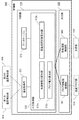
- FIG. 1 is a view showing the configuration of the cooling device 1000 in a transparent manner.
- the vertical direction G is shown by FIG.
- the cooling device 1000 is installed in a data center, for example.
- the cooling apparatus 1000 includes a local cooler 400 and an air conditioner 500.
- the evaporator 410 of the local cooler 400 and the electronic device 300 are provided in the server room 100.
- the air conditioner blower 510 and the heat exchanger 520 of the air conditioner 500 are provided in the machine room 200. Note that the inside of the casing 900 configured by connecting the server room 100 and the machine room 200 is hermetically sealed.
- the server room 100 is formed in a rectangular parallelepiped shape, for example.
- the server room 100 is hollow.
- a member having a heat insulating property for example, a concrete wall
- the server room 100 includes a rack 110.
- the server room 100 accommodates a rack 110 and some devices of the local cooler 400.
- the rack 110 is formed in a rectangular parallelepiped shape, for example.
- the rack 110 is hollow.
- the rack 110 is formed in a mesh shape. Therefore, air can go back and forth inside and outside the rack 110 through the mesh.
- the rack 110 accommodates the electronic device 300.
- the material of the rack 110 is a member having high thermal conductivity (for example, aluminum, aluminum alloy, etc.).
- the rack 110 is also referred to as an electronic device housing unit.
- the electronic device 300 may be accommodated in the server room 100 without providing the rack 110.
- the machine room 200 is formed in a rectangular parallelepiped shape, for example.
- the machine room 200 is provided so as to be adjacent to the server room 100.
- the machine room 200 is hollow.
- a member having heat insulating properties for example, a concrete wall
- a concrete wall is used as the material of the machine room 200.
- the machine room 200 accommodates some devices of the air conditioner 500.
- the machine room 200 includes a first storage unit 201 and a second storage unit 202.
- the first storage unit 201 stores the heat exchanger 520 of the air conditioner 500.
- the second storage unit 202 stores the air conditioning blower unit 510 of the air conditioner 500.
- the inside of the 1st accommodating part 201 and the 2nd accommodating part 202 is hollow.
- the 1st accommodating part 201 and the 2nd accommodating part 202 are formed in mesh shape. Therefore, air can travel between the inside and outside of the first housing portion 201 and the second housing portion 202 through the mesh.
- a member having high thermal conductivity for example, stainless steel or the like is used as the material of the first housing portion 201 and the second housing portion 202.
- the machine room 200 of the housing 900 includes a first opening 203 and a second opening 204.
- the first opening 203 and the second opening 204 communicate between the server room 100 and the machine room 200. That is, air can go back and forth between the server room 100 and the machine room 200 via the first opening 203 and the second opening 204.
- the electronic device 300 is accommodated in a rack 110.
- the electronic device 300 is, for example, a server (computing device), a router, or an uninterruptible power supply (UPS: Uninterruptible Power Supply).
- the electronic device 300 includes a heat generating component.
- a heat generating component refers to a component that generates heat when operated.
- the heat generating component is, for example, a CPU or an LSI.
- the heat generating component When the electronic device 300 performs various data processing, the heat generating component generates heat due to the data processing load.
- the cooling device 1000 has three circulation paths.
- the first circulation path (this circulation path is referred to as a first closed loop) is connected between the evaporator 410 and the condenser 420 via a vapor pipe 430 and a liquid pipe 440, and a refrigerant (COOLant: hereinafter referred to as COO). Circulate).
- a second circulation path (this circulation path is referred to as a second closed loop) passes the refrigerant COO between the condenser 420 and the refrigerator 530 via the first pipe 450 and the second pipe 460. Circulate.
- a third circulation path (this circulation path is referred to as a third closed loop) is connected between the refrigerator 530 and the heat exchanger 520 via the third pipe 540 and the fourth pipe 550, and the refrigerant COO. Circulate.
- Each of the first to third closed loops is independent as a closed space. Therefore, the refrigerant COO used in each of the first to third closed loops may be made of different materials.
- the refrigerant is made of, for example, a polymer material, and has a characteristic of vaporizing at a high temperature and liquefying at a low temperature.
- the same refrigerant COO for example, water
- the first and second closed loops may be configured by one closed loop.
- the refrigerant for example, hydrofluorocarbon (HFC) or hydrofluoroether (HFE) can be used as a low boiling point refrigerant.
- the refrigerant may be water.
- the water can be circulated in the local cooler 400 or the like using circulating power such as a pump.
- the method for filling the refrigerant COO in the closed spaces constituting the first to third closed loops is as follows. First, air is removed from the closed spaces constituting the first to third closed loops using a vacuum pump (not shown) or the like. Next, the refrigerant COO is injected into the closed space constituting the first to third closed loops. Thereby, the pressure in the closed space constituting the first to third closed loops becomes equal to the saturated vapor pressure of the refrigerant, and the boiling point of the refrigerant COO sealed in the closed space constituting the first to third closed loops is increased. Near room temperature. As described above, the method of filling the refrigerant COO in the closed spaces constituting the first to third closed loops has been described.
- the local cooler 400 includes an evaporator 410, a condenser 420, a steam pipe 430, and a liquid pipe 440.
- the evaporator 410 and the condenser 420 are connected by a vapor pipe 430 and a liquid pipe 440.
- the first tube 450 and the second tube 460 are connected to the condenser 420.
- the local cooler 400 corresponds to the cooler of this embodiment. However, the cooler of this embodiment should just be comprised including the evaporator 410 and the condenser 420 at least.
- the local cooler 400 has a refrigerant COO that circulates between the evaporator 410 and the condenser 420.
- a cavity is provided inside the evaporator 410 and the condenser 420.
- a cavity is provided in the refrigerator 530.
- the refrigerant COO is confined in a sealed state in a first closed space formed by the evaporator 410, the condenser 420, the vapor pipe 430, and the liquid pipe 440.
- the evaporator 410 is accommodated in the server room 100. As shown in FIG. 1, the evaporator 410 is connected to the condenser 420 by a vapor pipe 430 and a liquid pipe 440. As shown in FIG. 1, the evaporator 410 is disposed so as to face the electronic device 300. The evaporator 410 is provided vertically below the condenser 420 in the vertical direction G. The evaporator 410 is formed so that air can pass through, as will be described later with reference to FIG. The evaporator 410 receives heat of the electronic device 300 (for example, exhaust heat exhausted by the electronic device 300).
- the electronic device 300 for example, exhaust heat exhausted by the electronic device 300.
- the evaporator 410 receives the heat of the electronic device 300 through the ventilation by the air conditioning blower unit 510 of the air conditioner 500. Then, the evaporator 410 transmits the heat of the received electronic device 300 to the condenser 420 via the vapor pipe 430 using the refrigerant COO. More specifically, when the evaporator 410 receives heat from the electronic device 300, the refrigerant COO in the evaporator 410 changes phase from a liquid phase state to a gas phase state by absorbing the heat of the electronic device 300. The evaporator 410 transmits the heat of the received electronic device 300 to the condenser 420 via the vapor pipe 430 using the gas-phase refrigerant COO. Thereby, the heat of the electronic device 300 is transmitted to the condenser 420.
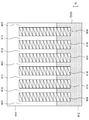
- FIG. 2 is a schematic transmission diagram schematically illustrating the internal configuration of the evaporator 410.
- FIG. 2 shows a vertical direction G.
- the evaporator 410 is formed in a flat plate shape, for example. As shown in FIG. 2, the evaporator 410 has a cavity inside and stores the refrigerant COO.
- the evaporator 410 includes an upper tank part 411, a lower tank part 412, a plurality of connecting pipe parts 413, and a plurality of evaporator fin parts 414.
- the upper tank portion 411 is disposed above the lower tank portion 412.
- the connecting pipe part 413 of the evaporator 410 connects the upper tank part 411 and the lower tank part 412. A plurality of connecting pipe portions 413 are provided.
- the evaporator fin portion 414 is provided between the connecting pipe portions 413. These evaporator fin portions 414 take heat away from the high-temperature blown air and transmit the received heat to the refrigerant COO in the connecting pipe portion 413. The received refrigerant COO undergoes a phase change from the liquid phase to the gas phase, and rises in the connecting pipe portion 413.
- the fin part 414 for evaporators is comprised by the several fin, and it is comprised so that air can pass between several fins. That is, in the region of the evaporator fin portion 414, air can pass from one main surface of the evaporator 410 to the other main surface.
- the steam pipe 430 connects the upper tank part 411 of the evaporator 410 and the condenser 420.
- the liquid pipe 440 connects the lower tank portion 412 of the evaporator 410 and the condenser 420.
- the condenser 420 is provided outside the server room 100 and the machine room 200.
- the condenser 420 may be provided in the server room 100 or the machine room 200.
- the condenser 420 is provided vertically above the evaporator 410 in the vertical direction G.
- the condenser 420 includes a first condenser 420A and a second condenser 420B.
- the first condenser 420A is connected to the evaporator 410 by a vapor pipe 430 and a liquid pipe 440.
- the second condenser 420B is connected to the first refrigerator 530A of the refrigerator 530 by a first tube 450 and a second tube 460.
- the first condenser 420A radiates the exhaust heat received by the evaporator 410. That is, the first condenser 420A receives the heat of the electronic device 300 received by the evaporator 410 and dissipates this heat.
- the first condenser 420A receives the heat of the electronic device 300 from the evaporator 410 via the gas-phase refrigerant COO. A part of the refrigerant COO in the gas phase state in the first condenser 420A is cooled in the first condenser 420A and changes into the refrigerant COO in the liquid phase state. At this time, the heat of the electronic device 300 received by the evaporator 410 is radiated.
- the first condenser 420A then flows out the refrigerant COO in the liquid phase that has undergone a phase change in the first condenser 420A to the evaporator 410. Further, the first condenser 420A transfers the heat of the electronic device 300 received by the evaporator 410 to the refrigerant COO in the second condenser 420B. In the second condenser 420B, the refrigerant COO changes from the liquid phase state to the gas phase state by the heat of the electronic device 300 received by the evaporator 410. The second condenser 420B transmits the refrigerant COO in the gas phase state to the first refrigerator 530A of the refrigerator 530 through the first pipe 450. In addition, the second condenser 420B receives the liquid-phase refrigerant COO from the first refrigerator 530A via the second pipe 460. In general, a plate heat exchanger or the like is used for the radiator 420.
- the steam pipe 430 connects the evaporator 410 and the first condenser 420A.
- the liquid pipe 440 connects the evaporator 410 and the first condenser 420A.
- the vapor pipe 430 and the liquid pipe 440 are used for circulating the refrigerant COO between the evaporator 410 and the first condenser 420A. That is, the vapor pipe 430 transports the refrigerant COO vaporized by the evaporator 410 (vapor phase refrigerant COO) from the evaporator 410 to the first condenser 420A.
- the liquid pipe 440 transports the refrigerant COO condensed and liquefied by the first condenser 420A (liquid phase refrigerant COO) from the first condenser 420A to the evaporator 410.
- the connection portion between the steam pipe 430 and the first condenser 420A is disposed at a higher position than the connection portion between the steam pipe 430 and the evaporator 410.
- the connecting portion between the liquid pipe 440 and the first condenser 420A is arranged at a higher position than the connecting portion between the liquid pipe 440 and the evaporator 410.
- the refrigerant COO increases in volume by about 200 times by shifting from the liquid phase state to the gas phase state. For this reason, it is preferable that the pipe diameter of the steam pipe 430 is larger than the pipe diameter of the liquid pipe 440.
- the steam pipe 430 and the liquid pipe 440 are formed of, for example, a metal such as an aluminum alloy, a rubber material, or the like.
- a coupler (not shown) and a flange (not shown) are used for connection with each member of the steam pipe 430 and the liquid pipe 440.
- the first tube 450 connects the second condenser 420B and the first refrigerator 530A.
- the second pipe 460 connects the second condenser 420B and the first refrigerator 530A.
- the first pipe 450 and the second pipe 460 are used to circulate the refrigerant COO between the second condenser 420B and the first refrigerator 530A.
- the first pipe 450 transports the refrigerant COO in the second condenser 420B from the second condenser 420B to the first refrigerator 530A.
- the second pipe 460 transports the refrigerant COO in the first refrigerator 530A from the first refrigerator 530A to the first condenser 420A.
- the first tube 450 and the second tube 460 are formed of, for example, a metal such as an aluminum alloy, a rubber material, or the like.
- a coupler (not shown) and a flange (not shown) are used for connection with each member of the 1st pipe
- the operation of the local cooler 400 will be described.
- the operation in which the refrigerant COO circulates in the first closed space (closed space formed by the first closed loop) formed by the evaporator 410, the first condenser 420A, the vapor pipe 430, and the liquid pipe 440. Will be explained.
- the operation of circulating the refrigerant COO in the second closed space formed by the first condenser 420A, the first refrigerator 530A, the first pipe 450, and the second pipe 460 will be described later.
- an operation in which the refrigerant COO circulates in the third closed space constituted by the second refrigerator 530B, the heat exchanger 520, the third pipe 540, and the fourth pipe 550 will be described later.
- the evaporator 410 is provided vertically below the condenser 420 in the vertical direction G.
- the evaporator 410 is provided vertically below the first condenser 420A in the vertical direction G.
- a natural circulation cooling method can be applied to the local cooler 400.
- the natural circulation system is a system in which the refrigerant COO is naturally circulated in the local cooler 400 using the density difference between the liquid phase and the gas phase.
- the evaporator 410 may not be provided vertically below the condenser 420 in the vertical direction G.
- the cooling structure including at least the evaporator 410, the first condenser 420A, the steam pipe 430, and the liquid pipe 440 functions as a cooling module and starts receiving heat from the electronic device 300.
- the evaporator 410 receives the heat of the electronic device 300 via the air blowing of the air-conditioning blower unit 510 described later.
- the refrigerant COO boils in the evaporator 410 and enters a gas phase state.
- the gas-phase refrigerant COO is also referred to as a vapor refrigerant.
- the refrigerant COO in the vapor state in the evaporator 410 flows into the first condenser 420A through the vapor pipe 430.
- the first condenser 420A dissipates heat contained in the refrigerant COO (heat of the electronic device 300) by cooling the gas-phase refrigerant COO.
- the refrigerant COO in the gas phase is changed into a liquid phase by being cooled in the first condenser 420A.
- coolant COO cooled in the 1st condenser 420A will be in a liquid phase state, and will flow in into the evaporator 410 through the liquid pipe 440 again.
- the refrigerant COO absorbs the heat of the electronic device 300 from the air passing through the evaporator 410 (including the heat of the electronic device 300) by the evaporator 410, and the evaporator 410, the vapor pipe 430, and the first.
- the condenser 420A and the liquid pipe 440 are sequentially circulated. Thereby, the heat of the electronic device 300 received by the evaporator 410 is radiated.
- the local cooler 400 circulates the refrigerant COO between the evaporator 410 and the first condenser 420A while changing the phase of the refrigerant COO (liquid phase ⁇ ⁇ gas phase).
- the heat received by the evaporator 410 (including the heat of the electronic device 300) is cooled.
- the air conditioner 500 includes an air conditioning blower unit 510, a heat exchanger 520, a refrigerator 530, a third pipe 540, a fourth pipe 550, and a control unit 560.
- the air conditioner 500 includes at least a heat exchanger 520 and a refrigerator 530.
- the air conditioner 500 circulates the refrigerant COO between the heat exchanger 520 and the refrigerator 530.
- the air conditioner 500 supplies air for cooling the heat of the electronic device 300 to the electronic device 300 using the air conditioning blower unit 510.
- the air conditioner 500 cools the air in the machine room 200.
- the refrigerator 530 of the air conditioner 500 radiates the heat of the electronic device 300 received from the condenser 420 and the heat exchanger 520 via the refrigerant COO to the outside air.
- the air-conditioning blower unit 510 is provided in the machine room 200 of the casing 900. More specifically, the air-conditioning blower unit 510 is provided in the second storage unit 202 of the machine room 200. The air-conditioning blower unit 510 supplies the air for cooling the electronic device 300 along the arrow A to the electronic device 300. The air-conditioning blower 510 is provided so as to face the electronic device 300 through the second opening 204. Thereby, the air sent by the air-conditioning blower unit 510 is efficiently supplied to the electronic device 300.
- the blower generally refers to a blower (including a fan and a blower) having a pressure ratio of about 1.1 to 2.
- the heat exchanger 520 is provided in the machine room 200 of the casing 900. More specifically, the heat exchanger 520 is provided in the first housing part 201 of the machine room 200. The heat exchanger 520 is connected to the second refrigerator 530B of the refrigerator 530 via the third tube 540 and the fourth tube 550. The heat exchanger 520 receives the exhaust heat of the electronic device 300. The heat exchanger 520 receives heat contained in the air in the machine room 200 via the refrigerant COO. Then, the heat exchanger 520 sends the refrigerant COO that has absorbed heat to the second refrigerator 530B via the third pipe 540. Further, the heat exchanger 520 receives the refrigerant COO cooled by the second cooler 530B through the fourth pipe 550.
- the refrigerator 530 is provided outside the server room 100 and the machine room 200.
- the refrigerator 530 includes a first refrigerator 530A and a second refrigerator 530B.
- the first refrigerator 530A is connected to the second condenser 420B via the first tube 450 and the second tube 460.
- the second refrigerator 530B is connected to the heat exchanger 520 via the third pipe 540 and the fourth pipe 550.
- the first refrigerator 530A dissipates the heat received by the condenser 420.
- the first refrigerator 530 ⁇ / b> A receives the refrigerant COO that has absorbed heat from the condenser 420 via the first pipe 450.
- the first refrigerator 530A cools the received refrigerant COO.
- the first refrigerator 530A sends the cooled refrigerant COO back to the second condenser 420B via the second pipe 460 again.
- the second refrigerator 530B radiates heat received by the heat exchanger 520.
- the second refrigerator 530B receives the refrigerant COO that has absorbed heat from the heat exchanger 520 through the third pipe 540.
- the second refrigerator 530B cools the received refrigerant COO.
- the second refrigerator 530B sends the cooled refrigerant COO back to the heat exchanger 520 again.
- the third pipe 540 connects between the heat exchanger 520 and the second refrigerator 530B.
- the third pipe 540 transports the refrigerant COO in the heat exchanger 520 from the heat exchanger 520 to the second refrigerator 530B.
- the fourth tube 550 connects between the heat exchanger 520 and the second refrigerator 530B.
- the fourth pipe 550 transports the refrigerant COO in the second refrigerator 530B from the second refrigerator 530B to the heat exchanger 520.
- the second condenser 420B transfers the heat of the electronic device 300 transferred from the evaporator 410 to the first condenser 420A in the first closed loop, from the first condenser 420A to the inside of the second condenser 420B. Received via refrigerant COO. At this time, the refrigerant COO in the second condenser 420B in the second closed loop changes from the liquid phase state to the refrigerant COO in the gas phase state by the heat of the electronic device 300. The second condenser 420B causes the refrigerant COO in a gas phase state to flow out to the first refrigerator 530A through the first pipe 450 in the second closed loop.
- the gas phase refrigerant COO in the second heat radiation 420B flows through the first pipe 450 and into the first refrigerator 530A.
- the heat contained in the refrigerant COO heat of the electronic device 300
- the refrigerant COO in the gas phase is phase-changed to the liquid phase by being cooled in the first refrigerator 530A.
- the refrigerant COO cooled in the first refrigerator 530A enters a liquid phase state and flows into the second condenser 420B through the second pipe 460.
- the refrigerant COO sequentially circulates through the second condenser 420B, the first pipe 450, the first refrigerator 530A, and the second pipe 460.
- the heat of the electronic device 300 received by the evaporator 410 is dissipated by the first refrigerator 530A via the second condenser 420B.
- the evaporator 410 is circulated between the second condenser 420B and the first refrigerator 530A while changing the phase of the refrigerant COO (liquid phase ⁇ ⁇ gas phase) in the second closed loop.
- the heat received by (including the heat of the electronic device 300) is cooled.
- the heat exchanger 520 receives the exhaust heat of the electronic device 300.
- the heat exchanger 520 receives heat contained in the air in the machine room 200 via the refrigerant COO.
- the refrigerant COO in the heat exchanger 520 in the third closed loop undergoes a phase change from the liquid phase state to the gas phase state refrigerant COO due to heat of the electronic device 300 or the like.
- the heat exchanger 520 causes the gas-phase refrigerant COO that has absorbed heat to flow out to the second refrigerator 530B via the third pipe 540. That is, the refrigerant COO in the gas phase state in the heat exchanger 520 flows into the second refrigerator 530B through the third pipe 540.
- the refrigerant COO in the gas phase state by cooling the refrigerant COO in the gas phase state, heat (such as heat of the electronic device 300) contained in the refrigerant COO is radiated.
- the refrigerant COO in the gas phase is phase-changed to the liquid phase by being cooled in the second refrigerator 530B.
- the refrigerant COO cooled in the second refrigerator 530B enters a liquid phase state and flows into the heat exchanger 520 through the fourth pipe 550.
- the refrigerant COO circulates through the heat exchanger 520, the third pipe 540, the second refrigerator 530B, and the fourth pipe 550 sequentially. Thereby, the exhaust heat etc. of the electronic device 300 are radiated by the second refrigerator 530B.
- the refrigerant COO is circulated between the heat exchanger 520 and the second refrigerator 530B while changing the phase (liquid phase ⁇ ⁇ gas phase), thereby exhausting the electronic device 300. Cool heat etc.
- water is generally used as the refrigerant COO.
- the above-described phase change does not occur.
- the control unit 560 is provided outside the server room 100 and the machine room 200. More specifically, the control unit 560 is provided on the roof of the server room 100.
- the control unit 560 may be provided in the server room 100 or the machine room 200.
- the control unit 560 can be installed in a local room installed in the server room 100 or the like.
- the control unit 560 may be provided in a cloud system (not shown) on a network (not shown).
- the control unit 560 is connected to the air-conditioning blower unit 510, the refrigerator 530, the first temperature detection unit 610, and the second temperature detection unit 620.
- the control unit 560 controls the operation of the air conditioning blower unit 510 and the refrigerator 530. The function of the control unit 560 will be described later.
- a first temperature detection unit 610 and a second temperature detection unit 620 are provided in the cooling device 1000.
- the first temperature detection unit 610 is provided between the electronic device 300 and the air conditioning blower unit 510.
- the first temperature detection unit 610 is connected to the control unit 560.
- the first temperature detection unit 610 detects a supply temperature Ta that is the temperature of air supplied from the air-conditioning blower unit 510 of the air-conditioner 500 to the electronic device 300.
- the first temperature detection unit 610 outputs the detected value of the supply temperature Ta to the control unit 560.
- the supply temperature is also called intake air temperature.
- the second temperature detection unit 620 is provided outside the server room 100 and the machine room 200.
- the second temperature detection unit 620 is connected to the control unit 560.
- the second temperature detection unit 620 detects an outside air temperature To that is the temperature of the air outside the server room 100 and the machine room 200.
- Second temperature detection unit 620 outputs the detected value of outside air temperature To to control unit 560.
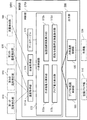
- FIG. 3 is a block diagram illustrating a configuration of the control unit 560.
- control unit 560 includes a determination unit 570 and an output unit 580.
- the determination unit 570 includes a temperature acquisition unit 571, a central control unit 572, and a data table 573.
- the temperature acquisition unit 571 is connected to the first temperature detection unit 610, the second temperature detection unit 620, and the central control unit 572.
- the temperature acquisition unit 571 acquires the supply temperature Ta detected by the first temperature detection unit 610 and the outside air temperature To detected by the second temperature detection unit 620.
- the temperature acquisition unit 571 outputs the supply temperature Ta and the outside air temperature To to the central control unit 572.
- the central control unit 572 is connected to the temperature acquisition unit 571, the output unit 580, and the data table 573.
- the central control unit 572 controls the entire control unit 560.
- the central control unit 572 accesses data stored in the data table 573.
- the central control unit 572 includes a refrigerator power calculation unit 572a, a device performance coefficient calculation unit 572b, and a blower power calculation unit 572c.
- the refrigerator power calculation unit 572a obtains the power consumption Wc of the refrigerator 530 based on the heat exchange amount Q of the electronic device 300 and the coefficient of performance COP_c of the refrigerator 530. Specific functions of the refrigerator power calculating unit 572a will be described in detail in the operation description described later.
- the device performance coefficient calculation unit 572b obtains the device performance coefficient ACOP (Apparatus's COP) based on the calorific value Q of the electronic device 300, the power consumption Wc of the refrigerator 530, and the power consumption Wf of the air conditioning blower unit 510.
- the apparatus performance coefficient ACOP is a coefficient of performance of an apparatus (here, the cooling apparatus 1000) including the evaporator 410, the condenser 420, the heat exchanger 520, the refrigerator 530, and the air conditioning blower unit 510. Specific functions of the apparatus performance coefficient calculation unit 572b will be described in detail in the operation description described later.
- the apparatus performance coefficient ACOP is an index (coefficient) of energy consumption efficiency of an apparatus (here, the cooling apparatus 1000) including the evaporator 410, the condenser 420, the heat exchanger 520, the refrigerator 530, and the air conditioning blower unit 510.
- the value represents the cooling capacity of the cooling device 1000 per 1 kW of power consumption.
- the blower power calculation unit 572c calculates the power consumption Wf of the air conditioning blower unit 510 based on the rotation speed r of the air conditioning blower unit 510. Specific functions of the blower power calculation unit 572c will be described in detail in the operation description described later.
- the data table 573 is connected to the central control unit 572.
- the data table 573 functions as a storage unit.
- the data table 573 stores, for example, parameters for calculating the apparatus performance coefficient ACOP and the like.
- the output unit 580 includes a blower rotation speed control unit 581 and a refrigerant temperature control unit 582.
- the blower rotational speed control unit 581 controls the rotational speed r of the air-conditioning blower unit 510 based on the apparatus performance coefficient ACOP.
- the refrigerant temperature control unit 582 controls the first refrigerant temperature Tin, which is the temperature of the refrigerant COO that flows out of the refrigerator 530, based on the apparatus performance coefficient ACOP.
- the first refrigerant temperature is also called a refrigerant discharge temperature.
- the electronic device 300, the local cooler 400, the air conditioner 500, etc. are activated.
- the heat of the electronic device 300 is cooled by the local cooler 400 and the air conditioner 500.
- the evaporator 410 receives the heat of the electronic device 300 via the air blowing of the air-conditioning blower unit 510. Then, the evaporator 410 transmits the heat of the received electronic device 300 to the first condenser 420A via the refrigerant COO that circulates between the evaporator 410 and the first condenser 420A.
- the first condenser 420A dissipates part of the heat of the electronic device 300. Further, the first condenser 420A transfers a part of the heat of the electronic device 300 to the refrigerant COO in the second condenser 420B included in the second closed loop.
- the second condenser 420B receives the heat of the electronic device 300 from the evaporator 410 via the refrigerant COO in the gas phase state in the first closed loop.
- the refrigerant COO in the second condenser 420B in the second closed loop changes from the liquid phase state to the refrigerant COO in the gas phase state by the heat of the electronic device 300.
- the second condenser 420B causes the refrigerant COO in a gas phase state to flow out to the first refrigerator 530A through the first pipe 450 in the second closed loop. That is, the gas phase refrigerant COO in the second heat radiation 420B flows through the first pipe 450 and into the first refrigerator 530A.
- the first refrigerator 530A dissipates heat contained in the refrigerant COO (heat of the electronic device 300) by cooling the gas-phase refrigerant COO.
- the refrigerant COO in the gas phase is phase-changed to the liquid phase by being cooled in the first refrigerator 530A. Then, the refrigerant COO cooled in the first refrigerator 530A enters a liquid phase state and flows into the second condenser 420B through the second pipe 460.
- the air-conditioning blower unit 510 supplies the air for cooling the electronic device 300 to the electronic device 300 along the arrow A. Thereby, the electronic device 300 is cooled by the ventilation by the air-conditioning blower unit 510.
- the air conditioning blower unit 510 is controlled by the control unit 560.
- the air blown by the air-conditioning blower unit 510 includes the exhaust heat of the electronic device 300 and is supplied to the evaporator 410 along the arrow B. A part of the blast supplied to the evaporator 410 passes through the evaporator 410 and flows upward in the vertical direction G as indicated by an arrow C.
- a part of the air that has passed through the evaporator 410 collides with the wall (ceiling) on the upper side in the vertical direction G of the server room 100 and flows in the directions of arrows D and E. Further, a part of the blast that has passed through the evaporator 410 flows into the machine room 200 through the first opening 203. In the machine room 200, a part of the blast that has passed through the evaporator 410 flows into the heat exchanger 520 of the air conditioner 500 as indicated by an arrow F by the suction input of the air conditioner 500.
- the heat exchanger 520 receives the exhaust heat of the electronic device 300.
- the heat exchanger 520 receives heat contained in the air in the machine room 200 via the refrigerant COO.
- the refrigerant COO in the heat exchanger 520 in the third closed loop undergoes a phase change from the liquid phase state to the gas phase state refrigerant COO due to heat of the electronic device 300 or the like.
- the heat exchanger 520 causes the gas-phase refrigerant COO that has absorbed heat to flow out to the second refrigerator 530B via the third pipe 540. That is, the refrigerant COO in the gas phase state in the heat exchanger 520 flows into the second refrigerator 530B through the third pipe 540.
- the refrigerant COO in the gas phase state by cooling the refrigerant COO in the gas phase state, heat (such as heat of the electronic device 300) contained in the refrigerant COO is radiated.
- the refrigerant COO in the gas phase is phase-changed to the liquid phase by being cooled in the second refrigerator 530B.
- the refrigerant COO cooled in the second refrigerator 530B enters a liquid phase state and flows into the heat exchanger 520 through the fourth pipe 550.
- the air conditioner 500 cools the air circulating in the casing 900 along the arrows A to F. That is, the air conditioner 500 absorbs heat that has not been absorbed by the local cooler 400 from the exhaust heat exhausted by the electronic device 300 and cools it.
- the air in the casing 900 is circulated sequentially along the arrows A to F. Therefore, the warm air (exhaust heat) discharged from the electronic device 300 along the arrow B is absorbed by the local cooler 400 and then heat-exchanged by the air conditioner 500.
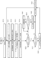
- FIG. 4 is a control flow diagram of the cooling device 1000.
- the apparatus performance coefficient calculation unit 572b of the control unit 560 calculates an initial ACOP (step (STEP: hereinafter simply referred to as S) 100).
- FIG. 5 is a part of the control flow diagram of the cooling device 1000 and is a flowchart showing the processing of S100 of FIG.
- the central control unit 572 sets the rotation speed r of the air-conditioning blower unit 510 and the first refrigerant temperature (refrigerant discharge temperature) Tin to predetermined values (S11).
- the blower rotation speed control unit 581 sets, for example, the maximum value of the rotation speed of the air conditioning blower unit 510 as a predetermined value.
- the refrigerant temperature control unit 582 sets, for example, the minimum value of the first refrigerant temperature as a predetermined value.
- the blower rotational speed control unit 581 lowers the rotational speed r of the air conditioning blower unit 510 from the predetermined value set in S11 by ⁇ r (where ⁇ r> 0) (S12).
- the central control unit 572 determines whether or not the supply temperature Ta is smaller than the upper limit threshold Th of the supply temperature Ta (S13).
- the central controller 572 determines whether the rotational speed r of the air conditioning blower 510 is the minimum value. It is determined whether or not (S14).
- the blower rotational speed control unit 581 sets the rotational speed r of the air conditioning blower unit 510. ⁇ r is increased (S15).
- the apparatus performance coefficient calculation unit 572b calculates an apparatus performance coefficient ACOP (S16).
- the blower power calculation unit 572c calculates the power consumption Wf0 of the air conditioning blower unit 510 based on the rotation speed r0 of the air conditioning blower unit 510 set in S15.
- R0 corresponds to rtarget in FIG.
- the central control unit 572 acquires the rotation speed r0 of the air conditioning blower unit 510 from the blower rotation number control unit 581.
- blower power calculation unit 572c of the central control unit 572 calculates the power consumption Wf0 of the air-conditioning blower unit 510 after waiting for a certain time (for example, about 1 minute) until the cooling performance is stabilized.
- FIG. 6 is a diagram showing the relationship between the power consumption Wf of the air-conditioning blower unit 510 and the power consumption Wc of the refrigerator at a specific outside air temperature To and a specific first refrigerant temperature Tin, and the blower rotational speed r.
- the power consumption (refrigerator power) Wc of the refrigerator changes in the blower rotational speed (the rotational speed of the air-conditioning blower unit 510). However, it becomes a constant value and does not change.
- the power (blower power) Wf0 of the air-conditioning blower unit 510 is proportional to the third power of the blower rotation number (the rotation number of the air-conditioning blower unit 510).
- the calculation formula for the power consumption Wf0 of the air conditioning blower unit 510 is obtained by using the rated power value Wf_max of the air conditioning blower unit 510, the rotational speed r0 of the air conditioning blower unit 510, and the maximum rotational speed r_max of the air conditioning blower unit 510 as It is expressed as follows.
- Wf0 Wf_max ⁇ (r0 / r_max) 3 Expression (1)
- a value calculated in advance by experiment for the power consumption Wf0 of the air-conditioning blower unit 510 may be stored in the data table 573.
- the blower power calculation unit 572c uses the power consumption Wf0 of the air conditioning blower unit 510 stored in the data table 573 instead of calculating the power consumption Wf0 of the air conditioning blower unit 510 using Equation (1). It can also be acquired.
- the refrigerator power calculation unit 572a obtains the power consumption Wc0 of the refrigerator 530 using Expression (2) based on the heat exchange amount Q of the electronic device 300 and the coefficient of performance COP_c0 of the refrigerator 530. .
- the coefficient of performance COP_c0 of the refrigerator 530 is stored in advance in the data table 573 in correspondence with the predetermined first refrigerant temperature Tin and the outside air temperature To.
- the calorific value Q of the electronic device 300 is a constant value.
- the apparatus performance coefficient calculation part 572b uses apparatus (3) based on the calorific value Q of the electronic device 300, the power consumption Wc of the refrigerator 530, and the power consumption Wf0 of the air-conditioning blower part 510 using the apparatus (3).
- the calculated apparatus performance coefficient ACOP is defined as the initial ACOP.
- the values calculated by Equation (1) and Equation (2) are used.
- cooling device 1000 calculates device performance coefficient ACOP.
- the cooling device 1000 performs the process of S16.
- the cooling device 1000 performs the process of S12.
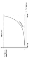
- FIG. 7 is a diagram showing the relationship between the rotation speed (blower rotation speed) r of the air-conditioning blower section 510 and the supply temperature Ta at a specific outside air temperature To and a specific first refrigerant temperature Tin.
- the supply temperature is also called intake air temperature.
- FIG. 7 shows an apparatus performance coefficient ACOP_1 corresponding to a predetermined value (r) of the rotation speed of the air-conditioning blower unit 510.
- FIG. 7 shows an apparatus performance coefficient ACOP_2 corresponding to the rotational speed (r ⁇ r) of the air conditioning blower unit 510.
- FIG. 7 shows an apparatus performance coefficient ACOP_3 corresponding to the rotation speed (r ⁇ 2 ⁇ r) of the air-conditioning blower unit 510.
- the maximum ACOP value when the supply temperature Ta is smaller than the upper limit threshold Th of the supply temperature Ta (Ta ⁇ Th) is set as the target ACOP (1) of the apparatus performance coefficient.
- the cooling device 1000 has a blower rotational speed (the rotational speed of the air-conditioning blower unit 510) at which ACOP is maximum when the supply temperature Ta is lower than the upper limit threshold Th of the supply temperature Ta (Ta ⁇ Th). Control aiming at a certain r_target is performed (S101 to S106 in FIG. 4).
- the cooling device 1000 increases the first refrigerant temperature Tin by ⁇ T. Further, the cooling device 1000 further sets the rotation speed r of the air-conditioning blower unit 510 to a predetermined value (r) (S101).
- the predetermined value here is set as a value close to the maximum value of the rotation speed r of the air-conditioning blower unit 510, for example, as shown in FIG.
- the refrigerant temperature control unit 582 increases the first refrigerant temperature T by ⁇ T. Further, the blower rotation speed control unit 581 sets the rotation speed r to the predetermined value described above.
- the central control unit 572 determines whether or not the supply temperature Ta is lower than the upper limit threshold Th of the supply temperature Ta (S102).
- the central control unit 572 determines whether the rotational speed r of the air conditioning blower unit 510 is the minimum value. Is determined (S103).
- the blower rotational speed control unit 581 sets the rotational speed r of the air conditioning blower unit 510 to ⁇ r. Increase (S105). The rotation speed of the air-conditioning blower unit 510 after the increase of ⁇ r is r1.
- the cooling device 1000 performs the process of S106.
- the blower rotation number control unit 581 performs control to reduce the rotation speed r of the air conditioning blower unit 510 by ⁇ r. This is performed (S104).
- the air conditioning blower unit 510 lowers the rotational speed r of the air conditioning blower unit 510 by ⁇ r according to the control of the blower rotational speed control unit 581.
- the cooling apparatus 1000 calculates an apparatus performance coefficient ACOP (1) as in S16 (S106).
- ACOP (1) corresponds to the case where the blower rotational speed is set to r1. Note that r1 corresponds to r target in FIG.
- the blower power calculation unit 572c calculates the power consumption Wf1 of the air conditioning blower unit 510 based on the rotation speed r1 of the air conditioning blower unit 510 set in S105.
- the central control unit 572 acquires the rotation speed r1 of the air-conditioning blower unit 510 from the blower rotation number control unit 581.
- blower power calculation unit 572c of the central control unit 572 calculates the power consumption Wf1 of the air conditioning blower unit 510 after waiting for a certain time (for example, about 1 minute) until the cooling performance is stabilized.
- the calculation formula for the power consumption Wf1 of the air conditioning blower unit 510 is expressed by the following equation (4) using the rated power value Wf_max of the air conditioning blower unit 510, the rotational speed r1 of the air conditioning blower unit 510, and the maximum rotational speed r_max of the air conditioning blower unit 510. It is expressed as follows. Wf1 corresponds to Wf when the rotation speed (blower rotation speed) of the air-conditioning blower unit 510 is set to r1.
- Formula (4) is based on Formula (1).
- Wf1 Wf_max ⁇ (r1 / r_max) 3 Expression (4)
- a value calculated in advance by experiment for the power consumption Wf1 of the air-conditioning blower unit 510 may be stored in the data table 573.
- the blower power calculation unit 572c uses the power consumption Wf1 of the air conditioning blower unit 510 stored in the data table 573 instead of calculating the power consumption Wf1 of the air conditioning blower unit 510 using Equation (4). It can also be acquired.
- the refrigerator power calculation unit 572a obtains the power consumption Wc of the refrigerator 530 using Expression (5) based on the heat exchange amount Q of the electronic device 300 and the coefficient of performance COP_c1 of the refrigerator 530. .
- the coefficient of performance COP_c1 of the refrigerator 530 is stored in advance in the data table 573 in correspondence with the first refrigerant temperature Tin + ⁇ T and the outside air temperature To.
- the central controller 572 acquires the coefficient of performance COP_c1 of the refrigerator 530 from the data table 573.
- the calorific value Q of the electronic device 300 is a constant value.
- the calorific value Q of the electronic device 300 is known in advance from a catalog or the like, and is stored in advance in the data table 573, for example.
- Wc1 corresponds to Wc when the fan rotation speed is set to r1.
- Formula (5) is based on Formula (2).
- the apparatus performance coefficient calculation part 572b uses apparatus (6) based on the calorific value Q of the electronic device 300, the power consumption Wc1 of the refrigerator 530, and the power consumption Wf1 of the air-conditioning blower part 510 using the apparatus (6).
- Wf1 and Wc1 in equation (6) the values calculated by equations (4) and (5) are used.
- the calorific value Q of the electronic device 300 is a constant value.
- the calorific value Q of the electronic device 300 is known in advance from a catalog or the like, and is stored in advance in the data table 573, for example.
- Formula (6) is based on Formula (3).
- cooling device 1000 calculates device performance coefficient ACOP (1).
- the central control unit 572 determines whether or not the apparatus performance coefficient ACOP (1) and the apparatus performance coefficient ACOP are substantially the same value (S116).
- the central control unit determines whether or not the apparatus performance coefficient ACOP (1) and the apparatus performance coefficient ACOP are substantially the same value (S116).
- the central control unit determines that the apparatus performance coefficient ACOP (1) and the apparatus performance coefficient ACOP have substantially the same value (ACOP (1) ⁇ ACOP).
- the central controller 572 determines that the apparatus performance coefficient ACOP (1) and the apparatus performance coefficient ACOP are substantially the same value (YES in S116)
- the central controller 572 determines that the outside air temperature To (1) and the outside air temperature To It is determined whether the absolute value of the difference value is smaller than the threshold value Tc (
- the threshold value Tc is determined as a temperature difference when the performance of the local cooler 400 changes.
- the threshold value Tc is set to 3 ° C., for example.
- the central control unit 572 determines that the absolute value of the difference value between the outside air temperature To and the outside air temperature To (1) is smaller than the threshold value Tc (S119, YES)
- the central control unit 572 causes the central control unit 572 to operate for a certain time (eg, 10 minutes) ), Wait (S121), and repeat the process of S119. That is, when the absolute value of the difference value between the outside air temperature To and the outside air temperature To (1) is smaller than the threshold value Tc, the central control unit 572 determines the amount of change in the outside air temperature To (
- the central control unit 572 determines that the absolute value of the difference value between the outside air temperature To and the outside air temperature To (1) is not smaller than the threshold value Tc (S119, NO).
- the central controller 572 determines that the outside air temperature To ( 1) is written in the data table 573 as a new outside air temperature (step S122). Thereafter, the central control unit 572 writes the apparatus performance coefficient ACOP (1) as a new apparatus performance coefficient in the data table 573 (step S123).
- the central control unit 572 determines the magnitude of the change amount of the outside air temperature To (
- the central controller 572 determines that the apparatus performance coefficient ACOP (1) and the apparatus performance coefficient ACOP are not substantially equal (S116, NO).
- the central controller 572 determines that the apparatus performance coefficient ACOP (1) is the apparatus performance coefficient. It is determined whether it is larger than ACOP (S117).
- the central control unit 572 determines that the apparatus performance coefficient ACOP (1) is larger than the apparatus performance coefficient ACOP (S117, YES)
- the central control unit 572 sets the apparatus performance coefficient ACOP (1) as a new apparatus performance coefficient. Is written in the data table 573 (step S123).
- the central control unit 572 determines that the apparatus performance coefficient ACOP (1) is not larger than the apparatus performance coefficient ACOP (S117, NO)
- the central control unit 572 determines the change in the first refrigerant temperature T.
- the sign of a certain ⁇ T (see S101) is inverted (S118).
- the central controller 572 writes the apparatus performance coefficient ACOP (1) as a new apparatus performance coefficient in the data table 573 under the condition that the sign of ⁇ T is inverted (step S123).
- the central control unit 572 performs processing such as comparison between ACOP and ACOP (1) and the like, and the target value (device performance coefficient maximum value) at which the apparatus performance coefficient ACOP is maximized. )
- the blower rotation speed control unit 581 sets the rotation speed of the air-conditioning blower unit 510 to the blower rotation speed corresponding to the device performance coefficient maximum value.
- the refrigerant temperature control unit 582 controls the refrigerator 530 so that the first refrigerant temperature Tin is a temperature corresponding to the apparatus performance coefficient maximum value.
- the air-conditioning blower unit 510 operates at the blower rotational speed corresponding to the maximum device performance coefficient.
- the refrigerator 530 flows out the refrigerant COO having the first refrigerant temperature Tin corresponding to the maximum apparatus coefficient of performance value to the second pipe 460 and the fourth pipe 550.
- the cooling device 1000 operates at the maximum device performance coefficient. That is, as described above, since the coefficient of performance is one of the indexes representing energy consumption efficiency, the cooling apparatus 1000 can operate with the highest energy consumption efficiency.
- the cooling device 1000 includes the evaporator 410, the condenser 420, the heat exchanger 520, the refrigerator 530, the air-conditioning blower unit 510 (the air blowing unit), And a control unit 560.
- the evaporator 410 receives the exhaust heat of the electronic device 300.
- the condenser 420 radiates the exhaust heat received by the evaporator 410.
- the heat exchanger 520 receives the exhaust heat of the electronic device 300.
- the refrigerator 530 circulates the refrigerant COO between the condenser 420 and the heat exchanger 520 to dissipate the exhaust heat received by the heat exchanger 520 and the evaporator 420.
- the air-conditioning blower unit 510 (the air blowing unit) supplies air for cooling the electronic device 300 to the electronic device 300.
- the control unit 560 controls the operation of the air conditioning blower unit 510 and the refrigerator 530.
- control unit 560 includes a blower power calculation unit 572c, a refrigerator power calculation unit 572a, an apparatus performance coefficient calculation unit 572b, a blower rotation speed control unit 581 (a blower rotation control unit), and a refrigerant temperature control unit 582. And have.
- the blower power calculation unit 572c calculates the power consumption Wf of the air conditioning blower unit 510 based on the rotation speed r of the air conditioning blower unit 510.
- the refrigerator power calculation unit 572a obtains the power consumption Wc of the refrigerator 530 based on the heat exchange amount Q of the electronic device 300 and the coefficient of performance COP_c of the refrigerator 530.
- the apparatus performance coefficient calculation unit 572b calculates the apparatus performance coefficient ACOP based on the calorific value Q of the electronic device 300, the power consumption Wc of the refrigerator 530, and the power consumption Wf of the air conditioning blower unit 510.
- the apparatus performance coefficient ACOP is a coefficient of performance of an apparatus including the evaporator 410, the condenser 420, the heat exchanger 520, the refrigerator 530, and the blower 510.
- the blower rotational speed control unit 581 controls the rotational speed r of the air-conditioning blower unit 510 based on the apparatus performance coefficient ACOP.
- the refrigerant temperature control unit 582 controls the first refrigerant temperature Tin, which is the temperature of the refrigerant COO that flows out of the refrigerator 530, based on the apparatus performance coefficient ACOP.
- the power consumption Wf of the air conditioning blower unit 510 is obtained by the blower power calculation unit 572c based on the rotation speed r of the air conditioning blower unit 510.
- the power consumption Wc of the refrigerator 530 is determined by the refrigerator power calculation unit 572a based on the heat exchange amount Q of the electronic device 300 and the coefficient of performance COP_c of the refrigerator 530.
- the apparatus performance coefficient ACOP is obtained by the apparatus performance coefficient calculation unit 572b based on the heat generation amount Q of the electronic device 300, the power consumption Wc of the refrigerator 530, and the power consumption Wf of the air conditioning blower unit 510.
- the coefficient of performance of the apparatus including the evaporator 410, the condenser 420, the heat exchanger 520, the refrigerator 530, and the air conditioning blower unit 510 is easily obtained from a plurality of parameters that can be easily obtained as the apparatus performance coefficient ACOP. Can do.
- the apparatus performance coefficient ACOP changes according to the change in the rotation speed (blower rotation speed) of the air-conditioning blower unit 510.
- the blower rotation control unit 581 controls the rotation speed (blower rotation speed) of the air-conditioning blower section 510 so that the apparatus performance coefficient ACOP becomes a high value (for example, near the maximum value) while the supply temperature Ta satisfies Th or less. be able to.
- the refrigerant temperature control unit 582 controls the refrigerator 530 to set the first refrigerant temperature Tin to a temperature corresponding to the apparatus performance coefficient maximum value while the supply temperature Ta satisfies Th or less.
- the cooling device 1000 can be operated more stably and with higher energy efficiency.
- the blower rotation control unit 581 includes the air conditioner blower unit 510 so that the apparatus performance coefficient ACOP is maximized while the supply temperature Ta satisfies Th or less.
- the rotational speed r is controlled.
- the refrigerant temperature control unit 582 controls the first refrigerant temperature Tin so that the apparatus performance coefficient ACOP is maximized while the supply temperature Ta satisfies Th or lower.
- the supply temperature Ta is the temperature of air supplied from the air conditioning blower unit 510 of the air conditioner 500 to the electronic device 300.
- Th is an upper limit threshold value of the supply temperature Ta.
- the blower rotation control unit 581 controls the supply temperature Ta so that the supply temperature Ta satisfies Th or less, and the rotation speed r of the air conditioning blower unit 510 is set to a value that maximizes the apparatus performance coefficient ACOP.
- the refrigerant temperature control unit 582 controls the first refrigerant temperature Tin to a value that maximizes the apparatus performance coefficient ACOP while controlling the supply temperature Ta to satisfy Th or less.
- the blower rotation control unit 581 satisfies the predetermined temperature after the apparatus performance coefficient ACOP reaches the maximum while the supply temperature Ta satisfies Th or less.
- the rotational speed of the air conditioning blower unit 510 may be controlled.
- the predetermined time is a time until the ambient temperature of the refrigerator 530 changes to a predetermined value.
- the predetermined time is the time until the ambient temperature of the refrigerator 530 changes to a predetermined value. After the time has elapsed, the rotation speed of the air-conditioning blower unit 510 and the refrigerant of the refrigerator 530 are determined. By controlling the discharge temperature (first refrigerant temperature), the apparatus performance coefficient ACOP can be maximized for any outside air temperature To.
- control method of the cooling device 1000 in the first embodiment of the present invention includes an evaporator 410, a condenser 420, a heat exchanger 520, a refrigerator 530, and an air-conditioning blower 510 (blower).
- a control method of the cooling device 1000 including the control unit 560.
- the control method of the cooling device 1000 includes a blower power calculation step, a refrigerator power calculation step, a device performance coefficient calculation step, a blower rotation control step, and a refrigerant temperature control step.
- the power consumption Wf of the air conditioning blower unit 510 is calculated based on the rotation speed r of the air conditioning blower unit 510.
- the power consumption Wc of the refrigerator 530 is obtained based on the heat exchange amount Q of the electronic device 300 and the coefficient of performance COP_c of the refrigerator 530.
- an apparatus performance coefficient ACOP is obtained based on the calorific value Q of the electronic device 300, the power consumption Wc of the refrigerator 530, and the power consumption Wf of the air conditioning blower unit 510.
- the rotation speed r of the air-conditioning blower 510 is controlled based on the apparatus performance coefficient ACOP.
- the first refrigerant temperature Tin which is the temperature of the refrigerant COO flowing out from the refrigerator 530, is controlled based on the apparatus performance coefficient ACOP.
- control program of the cooling device 1000 includes an evaporator 410, a condenser 420, a heat exchanger 520, a refrigerator 530, and an air conditioner blower unit 510 (blower unit).
- a control program of the cooling device 1000 including the control unit 560.
- the control program of the cooling device 1000 performs a process including a blower power calculation step, a refrigerator power calculation step, a device performance coefficient calculation step, a blower rotation control step, and a refrigerant temperature control step on a computer.
- FIG. 8 is a view illustrating the configuration of the cooling device 1000A.
- the vertical direction G is shown.
- constituent elements equivalent to those shown in FIGS. 1 to 7 are denoted by the same reference numerals as those shown in FIGS.
- the cooling device 1000A is installed in a data center, for example.
- the cooling device 1000 ⁇ / b> A includes a local cooler 400 and an air conditioner 500.
- the evaporator 410 of the local cooler 400 and the electronic device 300 are provided in the server room 100.
- the air conditioner blower 510 and the heat exchanger 520 of the air conditioner 500 are provided in the machine room 200. Note that the inside of the casing 900 configured by connecting the server room 100 and the machine room 200 is hermetically sealed.
- FIG. 8 differs from FIG. 1 in that a third temperature detection unit 630 and a flow rate detection unit 700 are provided.
- the third temperature detection unit 630 is connected to the control unit 560A.
- the third temperature detection unit 630 detects the second refrigerant temperature Tout, which is the temperature of the refrigerant COO flowing in the first pipe 450 from the condenser 420 (second condenser 420B) toward the refrigerator 530. .
- the flow rate detection unit 700 is connected to the control unit 560A.
- the flow rate detection unit 700 detects a refrigerant flow rate Qw that is a flow rate of the refrigerant COO that flows through the first pipe 450 from the condenser 420 (second condenser 420B) toward the refrigerator 530.
- the control unit 560A includes an air conditioning blower unit 510, a refrigerator 530, a first temperature detection unit 610, a second temperature detection unit 620, a third temperature detection unit 630, and a flow rate detection unit 700. It is connected.
- control parts acquire supply temperature Ta from the 1st temperature detection part 610.
- FIG. The controller 560A acquires the outside air temperature To from the second temperature detector 620.
- the controller 560A acquires the second refrigerant temperature Tout from the third temperature detector 630. Further, the control unit 560A acquires the refrigerant flow rate Qw from the flow rate detection unit 700.
- FIG. 9 is a block diagram illustrating a configuration of the control unit 560A.
- constituent elements equivalent to those shown in FIGS. 1 to 8 are denoted by the same reference numerals as those shown in FIGS.
- control unit 560A includes a determination unit 570A and an output unit 580.
- the determination unit 570A includes a temperature acquisition unit 571A, a central control unit 572A, a data table 573, and a flow rate acquisition unit 574.
- FIG. 3 and FIG. 9 are compared.
- the temperature acquisition unit 571 is connected to the first temperature detection unit 610, the second temperature detection unit 620, and the central control unit 572.
- the temperature acquisition unit 571A is connected to the first temperature detection unit 610, the second temperature detection unit 620, the third temperature detection unit 630, and the central control unit 572. Yes.
- FIG. 3 and FIG. 9 are different.
- FIG. 9 is different from FIG. 3 in that a flow rate detection unit 700, a flow rate acquisition unit 574, and a local cooler heat exchange amount calculation unit 572d are provided.
- the temperature acquisition unit 571A includes a supply temperature Ta detected by the first temperature detection unit 610, an outside air temperature To detected by the second temperature detection unit 620, and a first temperature detected by the third temperature acquisition unit 630. 2 refrigerant temperature Tout is acquired. In addition, the temperature acquisition unit 571A outputs the supply temperature Ta, the outside air temperature To, and the second refrigerant temperature Tout to the central control unit 572.
- the flow rate acquisition unit 574 acquires the refrigerant flow rate Qw detected by the flow rate detection unit 700.
- the flow rate acquisition unit 574 outputs the refrigerant flow rate Qw to the central control unit 572.
- the local cooler heat exchange amount calculation unit 572d obtains the heat exchange amount Qr of the local cooler 400 based on the refrigerant flow rate Qw, the first refrigerant temperature Tin, and the second refrigerant temperature Tout. Note that the heat exchange amount of the local cooler 400 is also referred to as an endothermic amount of the local cooler 400. A specific function of the local cooler heat exchange amount calculation unit 572d will be described in detail in an operation description to be described later.
- FIG. 10 is a control flow diagram of the cooling device 1000A.
- the apparatus performance coefficient calculation unit 572b of the control unit 560A calculates an initial ACOP (S210).
- S210 is the same process as S100 of FIGS.
- the cooling device 1000 increases the first refrigerant temperature (refrigerant discharge temperature) Tin by ⁇ T (S211).
- central control unit 572 outputs an instruction to change first refrigerant temperature Tin by + ⁇ T to refrigerant temperature control unit 582.
- the refrigerant temperature control unit 582 changes the first refrigerant temperature Tin by + ⁇ T in accordance with an instruction from the central control unit 572.
- the cooling device 1000 calculates the heat exchange amount Qr of the local cooler 400 after a predetermined time (for example, about 1 minute) has elapsed (S212). Specifically, the central control unit 572 outputs an instruction to calculate the heat exchange amount Qr of the local cooler 400 to the local cooler heat exchange amount calculation unit 572d.
- the local cooler heat exchange amount calculation unit 572d calculates the heat exchange amount Qr of the local cooler 400 using Equation (7) according to the instruction of the central control unit 572.
- ⁇ is a density.
- Cp in the formula (7) is a constant pressure specific heat.
- the cooling device 1000 reads the rotation speed (blower rotation speed) of the air-conditioning blower unit 510 from the data table 573, and sets the blower rotation speed to the read value (S213).
- central control unit 570A reads out the rotation speed (blower rotation speed) of air conditioning blower section 510 from data table 573.
- the rotation speed of the air conditioning blower unit 510 is stored in advance in the data table 573 corresponding to the heat exchange amount Qc of the air conditioner 500.
- the central control unit 570A calculates the heat exchange amount Qc of the air conditioner 500 from the heat exchange amount Qr of the local cooler 400 calculated in S212 using Equation (8). Then, central control unit 570A reads the blower rotation speed (rotation speed of air-conditioning blower section 510) corresponding to the calculated value of heat exchange amount Qc of air conditioner 500 from data table 573.
- the cooling apparatus 1000 calculates an apparatus performance coefficient ACOP (1) in the same manner as S106 in FIG.
- the blower power calculation unit 572c calculates the power consumption Wf1 of the air conditioning blower unit 510 based on the rotation speed r1 of the air conditioning blower unit 510 set in S213.
- the central control unit 572 acquires the rotation speed r1 of the air-conditioning blower unit 510 from the blower rotation number control unit 581.
- blower power calculation unit 572c of the central control unit 572 calculates the power consumption Wf1 of the air conditioning blower unit 510 after waiting for a certain time (for example, about 1 minute) until the cooling performance is stabilized.
- the calculation formula for the power consumption Wf1 of the air conditioning blower unit 510 is obtained by using the rated power value Wf_max of the air conditioning blower unit 510, the rotational speed r1 of the air conditioning blower unit 510, and the maximum rotational speed r_max of the air conditioning blower unit 510 as It is expressed as follows.
- Wf1 corresponds to Wf when the rotation speed (blower rotation speed) of the air-conditioning blower unit 510 is set to r1. Equation (9) is similar to equation (4).
- Wf1 Wf_max ⁇ (r1 / r_max) 3 Expression (9)
- a value calculated in advance by experiment for the power consumption Wf1 of the air-conditioning blower unit 510 may be stored in the data table 573.
- the blower power calculation unit 572c uses the power consumption Wf1 of the air conditioning blower unit 510 stored in the data table 573 instead of calculating the power consumption Wf1 of the air conditioning blower unit 510 using Equation (9). It can also be acquired.
- the refrigerator power calculation unit 572a obtains the power consumption Wc of the refrigerator 530 using the equation (10) based on the heat exchange amount Q of the electronic device 300 and the coefficient of performance COP_c1 of the refrigerator 530. .
- the coefficient of performance COP_c1 of the refrigerator 530 corresponds to COP_c when the rotation speed of the air-conditioning blower unit 510 is set to r1.
- the central controller 572 acquires the coefficient of performance COP_c1 of the refrigerator 530 from the data table 573.
- the calorific value Q of the electronic device 300 is a constant value.
- the calorific value Q of the electronic device 300 is known in advance from a catalog or the like, and is stored in advance in the data table 573, for example.
- Wc1 corresponds to Wc when the rotation speed of the air-conditioning blower unit 510 is set to r1.
- Formula (10) is based on Formula (5).
- the apparatus performance coefficient calculation part 572b uses apparatus (11) based on the calorific value Q of the electronic device 300, the power consumption Wc1 of the refrigerator 530, and the power consumption Wf1 of the air-conditioning blower part 510 using the apparatus (11). Determine the coefficient of performance ACOP (1).
- the calorific value Q of the electronic device 300 is a constant value.
- the calorific value Q of the electronic device 300 is known in advance from a catalog or the like, and is stored in advance in the data table 573, for example.
- Formula (11) is based on Formula (6).
- cooling device 1000 calculates device performance coefficient ACOP (1).
- FIG. 11 is a control flow diagram of a modified example of the cooling apparatus 1000A, and particularly shows a modified example in which the processes before and after S213 and S214 in FIG. 10 are changed.
- the central control unit 570 reads the rotation speed (blower rotation speed) of the air-conditioning blower section 510 from the data table 573, and sets the blower rotation speed to the read value. It was.
- the cooling device 1000A performs the process corresponding to S213, and associates the rotation speed of the air-conditioning blower unit 510 with the heat exchange amount Qc of the air conditioner 500, and stores it in the data table 573. I remember it.
- the central control unit 572A stores data on the rotational speed r of the air conditioning blower unit 510 for each heat exchange amount Qc of the air conditioner 500 in the data table 573. Is stored (S301). That is, the central control unit 572A checks whether data on the rotation speed r of the air conditioning blower unit 510 measured for each heat exchange amount Qc of the air conditioner 500 is stored in the data table 573.
- the central control unit 572A determines that the data of the rotation speed r of the air conditioning blower unit 510 for each heat exchange amount Qc of the air conditioner 500 is stored in the data table 573 (S301, YES), the central control The unit 572A reads the value of the blower rotation number (the rotation number of the air-conditioning blower unit 510) from the data table 573, and causes the blower rotation number control unit 581 to set the blower rotation number to the read rotation number ( S313).
- the blower rotational speed control unit 581 controls the blower rotational speed according to the control of the central control unit 572A. Note that S313 is the same processing as S213 in FIG.
- the central control unit 572A determines that the data of the rotation speed r of the air conditioning blower unit 510 for each heat exchange amount Qc of the air conditioner 500 is not stored in the data table 573 (S301, NO).
- the control unit 572A controls the blower rotation speed control unit 581 to change the blower rotation speed from the minimum value to the maximum value by a constant value (S302).
- the blower rotational speed control unit 581 controls the blower rotational speed according to the control of the central control unit 572A.
- the central control unit 572A acquires the blower rotational speed and ACOP (1) after a predetermined time (for example, 1 minute) every time the blower rotational speed is controlled, and stores it in the data table 573 (S302).
- the central control unit 572A writes the blower rotation speed and ACOP (1) when ACOP (1) is the highest in the data table 573 (S303).
- the blower rotation speed control unit changes the blower rotation speed to the blower rotation speed written in S303 according to the control of the central control unit 572A (S304).
- the apparatus performance coefficient calculation unit 572b of the central control unit 572A calculates ACOP (1) after a predetermined time (for example, 1 minute) (S314). Note that S313 is the same processing as S214 in FIG.
- the central control unit 572A determines whether or not the apparatus performance coefficient ACOP (1) and the apparatus performance coefficient ACOP are substantially the same value (S316).
- the process of S316 is the same process as S216 of FIG.
- the central control unit 572A determines that the apparatus performance coefficient ACOP (1) and the apparatus performance coefficient ACOP are substantially the same value (S316, YES)
- the central control unit 572A determines the outside air temperature To (1) and the outside air temperature To. It is determined whether or not the absolute value of the difference value is smaller than the threshold value Tc (
- Tc
- the central control unit 572A determines that the absolute value of the difference value between the outside air temperature To and the outside air temperature To (1) is smaller than the threshold value Tc (S319, YES), the central control unit 572A performs a certain time (for example, 10 minutes) ), Waits (S321), and repeats the process of S319.
- the process of S321 is the same process as S221 of FIG.
- the central controller 572A determines that the absolute value of the difference value between the outside air temperature To and the outside air temperature To (1) is not smaller than the threshold value Tc (S319, NO)
- the central controller 572A displays the outside air temperature To ( 1) is written in the data table 573 as a new outside air temperature (S322).
- the central control unit 572 writes the apparatus performance coefficient ACOP (1) as a new apparatus performance coefficient in the data table 573 (step S323).
- the cooling device 1000 performs the process of S211 in FIG. Note that the processing of S322 and S323 is the same processing as S222 and S223 of FIG.
- the central controller 572A determines that the apparatus performance coefficient ACOP (1) and the apparatus performance coefficient ACOP are not substantially the same value (S316, NO)
- the central controller 572A determines that the apparatus performance coefficient ACOP (1) is the apparatus performance coefficient. It is determined whether it is larger than ACOP (S317).
- the process of S317 is the same process as S217 of FIG.
- the central controller 572A determines that the apparatus performance coefficient ACOP (1) is larger than the apparatus performance coefficient ACOP (S317, YES), the central controller 572A performs the process of S323.
- the central control unit 572A determines that the apparatus performance coefficient ACOP (1) is not larger than the apparatus performance coefficient ACOP (S317, NO)
- the central control unit 572A determines the amount of change in the refrigerant discharge temperature of the refrigerator 530.
- the sign of ⁇ T (see S211) is inverted (S318). Note that the process of S318 is the same as S218 of FIG. Thereafter, the central control unit 572A performs the process of S323. Furthermore, the cooling device 1000 performs the process of S211 in FIG.
- the cooling device 1000A further includes a local cooler heat exchange amount calculation unit 572d.
- the local cooler heat exchange amount calculation unit 572d obtains the local cooler heat exchange amount Qr based on the first refrigerant temperature (refrigerant discharge temperature) Tin, the second refrigerant temperature Tout, and the refrigerant flow rate Qw.
- the second refrigerant temperature Tout is the temperature of the refrigerant COO that flows through the first pipe 450 from the condenser 420 toward the refrigerator 530.
- the first pipe 450 transports the refrigerant COO from the condenser 420 to the refrigerator 530.
- the refrigerant flow rate Qw is the flow rate of the refrigerant COO that flows through the first pipe 450.
- the refrigerator power calculation unit 572a obtains the power consumption Wc of the refrigerator 530 based on the heat exchange amount Qr of the local cooler, the heat exchange amount Qc of the air conditioner, and the coefficient of performance of the refrigerator.
- FIG. 12 is a diagram illustrating a configuration of the cooling device 1000B.
- the same components as those shown in FIGS. 1 to 11 are denoted by the same reference numerals as those shown in FIGS.
- the cooling device 1000B is installed in a data center, for example.
- the cooling device 1000B includes an evaporator 410, a condenser 420, a heat exchanger 520, a refrigerator 530, an air-conditioning blower 510 (blower), and a controller 560B. It has.
- the evaporator 410 receives the exhaust heat of the electronic device 300.
- the condenser 420 radiates the exhaust heat received by the evaporator 410.
- the heat exchanger 520 receives the exhaust heat of the electronic device 300.
- the refrigerator 530 circulates the refrigerant COO between the condenser 420 and the heat exchanger 520 to dissipate the exhaust heat received by the heat exchanger 520 and the evaporator 420.
- the air-conditioning blower unit 510 (the air blowing unit) supplies air for cooling the electronic device 300 to the electronic device 300.
- the control unit 560B controls the operations of the air-conditioning blower unit 510 and the refrigerator 530.
- control unit 560B includes a blower power calculation unit 572c, a refrigerator power calculation unit 572a, an apparatus performance coefficient calculation unit 572b, a blower rotation speed control unit 581 (a blower rotation control unit), and a refrigerant temperature control unit 582. And have.
- the blower power calculation unit 572c calculates the power consumption Wf of the air conditioning blower unit 510 based on the rotation speed r of the air conditioning blower unit 510.
- the refrigerator power calculation unit 572a obtains the power consumption Wc of the refrigerator 530 based on the heat exchange amount Q of the electronic device 300 and the coefficient of performance COP_c of the refrigerator 530.
- the apparatus performance coefficient calculation unit 572b calculates the apparatus performance coefficient ACOP based on the calorific value Q of the electronic device 300, the power consumption Wc of the refrigerator 530, and the power consumption Wf of the air conditioning blower unit 510.
- the apparatus performance coefficient ACOP is a coefficient of performance of an apparatus including the evaporator 410, the condenser 420, the heat exchanger 520, the refrigerator 530, and the blower 510.
- the blower rotational speed control unit 581 controls the rotational speed r of the air-conditioning blower unit 510 based on the apparatus performance coefficient ACOP.
- the refrigerant temperature control unit 582 controls the first refrigerant temperature Tin, which is the temperature of the refrigerant COO that flows out of the refrigerator 530, based on the apparatus performance coefficient ACOP.
- the cooling device 1000B in the present embodiment has the same effects as the cooling device 1000 in the first embodiment.
- the power consumption Wf of the air conditioning blower unit 510 is obtained by the blower power calculation unit 572c based on the rotation speed r of the air conditioning blower unit 510.
- the power consumption Wc of the refrigerator 530 is obtained by the device performance coefficient calculation unit 572b based on the heat exchange amount Q of the electronic device 300 and the performance coefficient COP_c of the refrigerator 530.
- the apparatus performance coefficient ACOP is obtained by the apparatus performance coefficient calculation unit 572b based on the heat generation amount Q of the electronic device 300, the power consumption Wc of the refrigerator 530, and the power consumption Wf of the air conditioning blower unit 510.
- the coefficient of performance of the device including the evaporator 410, the condenser 420, the heat exchanger 520, the refrigerator 530, and the blower 510 can be easily obtained as a device performance coefficient ACOP from a plurality of parameters that can be easily obtained. it can.
- the apparatus performance coefficient ACOP changes according to the change in the rotation speed (blower rotation speed) of the air-conditioning blower unit 510.
- the blower rotation control unit 581 controls the rotation speed (blower rotation speed) of the air-conditioning blower section 510 so that the apparatus performance coefficient ACOP becomes a high value (for example, near the maximum value) while the supply temperature Ta satisfies Th or less. be able to.
- the refrigerant temperature control unit 582 controls the refrigerator 530 to set the first refrigerant temperature Tin to a temperature corresponding to the apparatus performance coefficient maximum value while the supply temperature Ta satisfies Th or less.
- FIG. 13 is a diagram illustrating an example of an information processing apparatus that implements the control units 560, 560A, 560B, and the like.
- the information processing apparatus 2000 includes the following configuration as an example.
- CPU Central Processing Unit
- ROM Read Only Memory
- RAM Random Access Memory
- a drive device 2007 for reading and writing the recording medium 2006
- Each component of each device in each embodiment is realized by the CPU 2001 acquiring and executing a program 2004 that realizes these functions.
- a program 2004 that realizes the function of each component of each device is stored in advance in the storage device 2005 or the RAM 2003, for example, and is read out by the CPU 2001 as necessary.
- each device may be realized by an arbitrary combination of an information processing device 2000 and a program that are different for each component.
- a plurality of components included in each device may be realized by an arbitrary combination of one information processing device 2000 and a program.
- part or all of each component of each device is realized by a general-purpose or dedicated circuit including a processor or the like, or a combination thereof. These may be configured by a single chip or may be configured by a plurality of chips connected via a bus.
- each component of each device may be realized by a combination of the above-described circuit and the like and a program.
- the plurality of information processing devices and circuits may be centrally arranged or distributedly arranged. Also good.
- the information processing apparatus, the circuit, and the like may be realized as a form in which each is connected via a communication network, such as a client and server system and a cloud computing system.
- the blowing unit rotation control unit is configured so that a supply temperature, which is a temperature of air supplied from the blowing unit to the electronic device, satisfies a maximum threshold value of the supply temperature or less, and the apparatus performance coefficient becomes maximum
- the refrigerant temperature control unit controls the first refrigerant temperature so that the apparatus performance coefficient is maximized while the supply temperature satisfies the upper limit threshold value of the supply temperature or less.
- the cooling device according to appendix 1 or 2
- the blower rotation control unit is configured to perform a predetermined time after the supply coefficient, which is the temperature of air supplied from the blower to the electronic device, satisfies the upper limit threshold of the supply temperature and the apparatus performance coefficient becomes maximum.
- the cooling device according to appendix 1 or 2 which controls the number of rotations of the air blowing unit after elapse of time.
- Appendix 5 The cooling device according to appendix 4, wherein the predetermined time is a time until the temperature around the refrigerator changes to a predetermined value.
- An evaporator that receives the exhaust heat of the electronic device; A condenser that dissipates the exhaust heat received by the evaporator; A heat exchanger that receives the exhaust heat of the electronic device; A refrigerator that circulates refrigerant between the condenser and the heat exchanger, and dissipates exhaust heat received by the heat exchanger and the evaporator; An air blower for supplying air to the electronic device for cooling the electronic device; A control method for a cooling device comprising a control unit that controls the operation of the blower unit and the refrigerator, A blower power calculation step for calculating the power consumption of the blower unit based on the rotational speed of the blower unit; A refrigerator power calculation step for obtaining power consumption of the refrigerator based on the calorific value of the electronic device and the coefficient of performance of the refrigerator; An apparatus including the evaporator, the condenser, the heat exchanger, the refrigerator, and the blower unit based on the heat generation amount of the electronic device, the power consumption of the
- An evaporator that receives the exhaust heat of the electronic device; A condenser that dissipates the exhaust heat received by the evaporator; A heat exchanger that receives the exhaust heat of the electronic device; A refrigerator that circulates refrigerant between the condenser and the heat exchanger, and dissipates exhaust heat received by the heat exchanger and the evaporator; An air blower for supplying air to the electronic device for cooling the electronic device; A control method for a cooling device comprising a control unit that controls the operation of the blower unit and the refrigerator, Based on the number of rotations of the blower, calculate the power consumption of the blower, Based on the calorific value of the electronic device and the coefficient of performance of the refrigerator, find the power consumption of the refrigerator, An apparatus including the evaporator, the condenser, the heat exchanger, the refrigerator, and the blower unit based on the heat generation amount of the electronic device, the power consumption of the refrigerator, and the power consumption of the blower unit The coefficient of performance
- An evaporator that receives the exhaust heat of the electronic device; A condenser that dissipates the exhaust heat received by the evaporator; A heat exchanger that receives the exhaust heat of the electronic device; A refrigerator that circulates refrigerant between the condenser and the heat exchanger, and dissipates exhaust heat received by the heat exchanger and the evaporator; An air blower for supplying air to the electronic device for cooling the electronic device; A control program for a cooling device including a control unit that controls the operation of the blower unit and the refrigerator, A blower power calculation step for calculating the power consumption of the blower unit based on the rotational speed of the blower unit; A refrigerator power calculation step for obtaining power consumption of the refrigerator based on the calorific value of the electronic device and the coefficient of performance of the refrigerator; An apparatus including the evaporator, the condenser, the heat exchanger, the refrigerator, and the blower unit based on the heat generation amount of the electronic device, the power consumption of the refrigerator
- An evaporator that receives the exhaust heat of the electronic device; A condenser that dissipates the exhaust heat received by the evaporator; A heat exchanger that receives the exhaust heat of the electronic device; A refrigerator that circulates refrigerant between the condenser and the heat exchanger, and dissipates exhaust heat received by the heat exchanger and the evaporator; An air blower for supplying air to the electronic device for cooling the electronic device; A control program for a cooling device including a control unit that controls the operation of the blower unit and the refrigerator, Based on the number of rotations of the blower, calculate the power consumption of the blower, Based on the calorific value of the electronic device and the coefficient of performance of the refrigerator, find the power consumption of the refrigerator, An apparatus including the evaporator, the condenser, the heat exchanger, the refrigerator, and the blower unit based on the heat generation amount of the electronic device, the power consumption of the refrigerator, and the power consumption of the blower unit The coefficient of performance of
- An evaporator that receives the exhaust heat of the electronic device; A condenser that dissipates the exhaust heat received by the evaporator; A heat exchanger that receives the exhaust heat of the electronic device; A refrigerator that circulates refrigerant between the condenser and the heat exchanger, and dissipates exhaust heat received by the heat exchanger and the evaporator; An air blower for supplying air to the electronic device for cooling the electronic device; A storage medium for storing a control program of a cooling device including a control unit that controls the operation of the blower and the refrigerator, A blower power calculation step for calculating the power consumption of the blower unit based on the rotational speed of the blower unit; A refrigerator power calculation step for obtaining power consumption of the refrigerator based on the calorific value of the electronic device and the coefficient of performance of the refrigerator; An apparatus including the evaporator, the condenser, the heat exchanger, the refrigerator, and the blower unit based on the heat generation amount of the electronic device,
- An evaporator that receives the exhaust heat of the electronic device; A condenser that dissipates the exhaust heat received by the evaporator; A heat exchanger that receives the exhaust heat of the electronic device; A refrigerator that circulates refrigerant between the condenser and the heat exchanger, and dissipates exhaust heat received by the heat exchanger and the evaporator; An air blower for supplying air to the electronic device for cooling the electronic device; A storage medium for storing a control program of a cooling device including a control unit that controls the operation of the blower and the refrigerator, Based on the number of rotations of the blower, calculate the power consumption of the blower, Based on the calorific value of the electronic device and the coefficient of performance of the refrigerator, find the power consumption of the refrigerator, An apparatus including the evaporator, the condenser, the heat exchanger, the refrigerator, and the blower unit based on the heat generation amount of the electronic device, the power consumption of the refrigerator, and the power consumption of the blower
Landscapes
- Engineering & Computer Science (AREA)
- Physics & Mathematics (AREA)
- General Engineering & Computer Science (AREA)
- Microelectronics & Electronic Packaging (AREA)
- Thermal Sciences (AREA)
- Theoretical Computer Science (AREA)
- Mechanical Engineering (AREA)
- Computer Hardware Design (AREA)
- Chemical & Material Sciences (AREA)
- Combustion & Propulsion (AREA)
- Human Computer Interaction (AREA)
- General Physics & Mathematics (AREA)
- Fluid Mechanics (AREA)
- Cooling Or The Like Of Electrical Apparatus (AREA)
- Air Conditioning Control Device (AREA)
Abstract
Le problème décrit par la présente invention est de fournir un appareil de refroidissement, etc., qui peut être utilisé avec une stabilité supérieure et un rendement énergétique supérieur. À cet effet, selon la présente invention, une unité de calcul de puissance de congélateur 572a calcule la consommation d'énergie Wc d'un congélateur 530 sur la base de la quantité d'échange de chaleur Q d'un dispositif électronique 300 et du coefficient de performances COP_c du congélateur 530. Une unité de calcul de coefficient de performances d'appareil 572b calcule un coefficient de performances d'appareil ACOP sur la base de la quantité de génération de chaleur Q du dispositif électronique 300, de la consommation d'énergie Wc, et de la consommation d'énergie Wf d'une unité de soufflante de conditionnement d'air 510. Le coefficient de performances d'appareil ACOP représente le coefficient de performances d'un appareil qui comprend : un évaporateur 410 ; un condensateur 420 ; un échangeur de chaleur 520 ; le congélateur 530 ; et l'unité de soufflante de conditionnement d'air 510. L'unité de commande de vitesse de rotation de soufflante 581 commande la vitesse de rotation r de l'unité de soufflante de conditionnement d'air 510 sur la base du coefficient de performances d'appareil ACOP. Une unité de régulation de température de fluide frigorigène 582 régule une première température de fluide frigorigène Tin qui est la température d'un fluide frigorigène COO s'écoulant en dehors du congélateur 530.
Priority Applications (2)
| Application Number | Priority Date | Filing Date | Title |
|---|---|---|---|
| JP2018507413A JP6904333B2 (ja) | 2016-03-24 | 2017-03-23 | 冷却装置、制御方法および記憶媒体 |
| US16/087,261 US10705582B2 (en) | 2016-03-24 | 2017-03-23 | Cooling apparatus, control method, and storage medium |
Applications Claiming Priority (2)
| Application Number | Priority Date | Filing Date | Title |
|---|---|---|---|
| JP2016060682 | 2016-03-24 | ||
| JP2016-060682 | 2016-03-24 |
Publications (1)
| Publication Number | Publication Date |
|---|---|
| WO2017164326A1 true WO2017164326A1 (fr) | 2017-09-28 |
Family
ID=59900270
Family Applications (1)
| Application Number | Title | Priority Date | Filing Date |
|---|---|---|---|
| PCT/JP2017/011790 Ceased WO2017164326A1 (fr) | 2016-03-24 | 2017-03-23 | Appareil de refroidissement, procédé de commande et support de stockage |
Country Status (3)
| Country | Link |
|---|---|
| US (1) | US10705582B2 (fr) |
| JP (1) | JP6904333B2 (fr) |
| WO (1) | WO2017164326A1 (fr) |
Cited By (1)
| Publication number | Priority date | Publication date | Assignee | Title |
|---|---|---|---|---|
| CN110418546A (zh) * | 2018-04-30 | 2019-11-05 | 百度(美国)有限责任公司 | 用于数据中心的热控制的气流管理系统 |
Families Citing this family (4)
| Publication number | Priority date | Publication date | Assignee | Title |
|---|---|---|---|---|
| DE102013221516A1 (de) * | 2013-10-23 | 2015-04-23 | Bayerische Motoren Werke Aktiengesellschaft | Luftversorgungseinrichtung für einen Fahrzeugsitz und Verfahren zum Betreiben der Luftversorgungseinrichtung |
| US10772241B2 (en) * | 2018-04-23 | 2020-09-08 | Dell Products, L.P. | Closed-loop supplemental heater system in an air handler system of outside air cooled data center |
| US10912229B1 (en) * | 2019-08-15 | 2021-02-02 | Baidu Usa Llc | Cooling system for high density racks with multi-function heat exchangers |
| US12426214B1 (en) * | 2024-03-05 | 2025-09-23 | Shumate Engineering, PLLC | Hybrid dry adiabatic cooling chilled water plant for data centers and other IT environments |
Citations (5)
| Publication number | Priority date | Publication date | Assignee | Title |
|---|---|---|---|---|
| JP2008002743A (ja) * | 2006-06-21 | 2008-01-10 | Daikin Ind Ltd | 冷凍装置 |
| JP2012193903A (ja) * | 2011-03-16 | 2012-10-11 | Fuji Electric Co Ltd | 外気利用空調システム、その外気熱交換システム |
| US20140183957A1 (en) * | 2011-12-30 | 2014-07-03 | Scrutiny, Inc. | FRAME (Forced Recuperation, Aggregation and Movement of Exergy) |
| JP2014157494A (ja) * | 2013-02-15 | 2014-08-28 | Panasonic Corp | サーバー冷却システム |
| WO2014192252A1 (fr) * | 2013-05-28 | 2014-12-04 | 日本電気株式会社 | Système de refroidissement et procédé de refroidissement |
Family Cites Families (6)
| Publication number | Priority date | Publication date | Assignee | Title |
|---|---|---|---|---|
| US20010019120A1 (en) * | 1999-06-09 | 2001-09-06 | Nicolas E. Schnur | Method of improving performance of refrigerant systems |
| DE20001253U1 (de) * | 2000-01-25 | 2001-06-07 | Liebherr-Hausgeräte GmbH, 88416 Ochsenhausen | Kühlgerät mit einem Kühl-, einem Kaltlager- und einem Gefrierfach |
| JP4028502B2 (ja) * | 2004-03-15 | 2007-12-26 | 東洋熱工業株式会社 | 冷凍機の冷却水制御方法 |
| JP2008134013A (ja) * | 2006-11-29 | 2008-06-12 | Toyo Netsu Kogyo Kk | 冷熱源機の運転制御方法及びこれを用いた冷熱源システム |
| US8516832B2 (en) * | 2010-08-30 | 2013-08-27 | B/E Aerospace, Inc. | Control system for a food and beverage compartment thermoelectric cooling system |
| US11009250B2 (en) * | 2015-06-30 | 2021-05-18 | Emerson Climate Technologies Retail Solutions, Inc. | Maintenance and diagnostics for refrigeration systems |
-
2017
- 2017-03-23 JP JP2018507413A patent/JP6904333B2/ja not_active Expired - Fee Related
- 2017-03-23 US US16/087,261 patent/US10705582B2/en not_active Expired - Fee Related
- 2017-03-23 WO PCT/JP2017/011790 patent/WO2017164326A1/fr not_active Ceased
Patent Citations (5)
| Publication number | Priority date | Publication date | Assignee | Title |
|---|---|---|---|---|
| JP2008002743A (ja) * | 2006-06-21 | 2008-01-10 | Daikin Ind Ltd | 冷凍装置 |
| JP2012193903A (ja) * | 2011-03-16 | 2012-10-11 | Fuji Electric Co Ltd | 外気利用空調システム、その外気熱交換システム |
| US20140183957A1 (en) * | 2011-12-30 | 2014-07-03 | Scrutiny, Inc. | FRAME (Forced Recuperation, Aggregation and Movement of Exergy) |
| JP2014157494A (ja) * | 2013-02-15 | 2014-08-28 | Panasonic Corp | サーバー冷却システム |
| WO2014192252A1 (fr) * | 2013-05-28 | 2014-12-04 | 日本電気株式会社 | Système de refroidissement et procédé de refroidissement |
Cited By (2)
| Publication number | Priority date | Publication date | Assignee | Title |
|---|---|---|---|---|
| CN110418546A (zh) * | 2018-04-30 | 2019-11-05 | 百度(美国)有限责任公司 | 用于数据中心的热控制的气流管理系统 |
| US10897836B2 (en) | 2018-04-30 | 2021-01-19 | Baidu Usa Llc | Airflow management system for thermal control of data centers |
Also Published As
| Publication number | Publication date |
|---|---|
| US10705582B2 (en) | 2020-07-07 |
| JP6904333B2 (ja) | 2021-07-14 |
| JPWO2017164326A1 (ja) | 2019-02-07 |
| US20190179384A1 (en) | 2019-06-13 |
Similar Documents
| Publication | Publication Date | Title |
|---|---|---|
| JP6750611B2 (ja) | 相変化冷却装置および相変化冷却方法 | |
| US9288931B2 (en) | Cooling system and device housing apparatus using the same | |
| JP6904333B2 (ja) | 冷却装置、制御方法および記憶媒体 | |
| JP5110510B2 (ja) | 装置を冷却する技術 | |
| Ohadi et al. | A comparison analysis of air, liquid, and two-phase cooling of data centers | |
| JP5907247B2 (ja) | 一体型空調システム、その制御装置 | |
| US12507385B2 (en) | Control systems for air-assisted and liquid-cooled enclosures | |
| JP2012007865A (ja) | 冷却システム | |
| US9983641B2 (en) | Tunable two phase liquid cooling thermal management method and apparatus | |
| WO2019017297A1 (fr) | Dispositif de réfrigération à changement de phase et procédé de réfrigération à changement de phase | |
| JP2005249258A (ja) | 冷却システム | |
| JPWO2018131555A1 (ja) | バルブ制御装置、冷却装置、バルブ制御方法およびプログラム記憶媒体 | |
| JP2009231529A (ja) | 電子機器の冷却システム | |
| WO2019181972A1 (fr) | Dispositif de refroidissement, procédé de commande et support de stockage | |
| JP6211799B2 (ja) | 装置冷却システムおよび装置冷却システムの制御方法 | |
| CN117154285A (zh) | 一种水冷机温度控制方法、系统、设备及介质 | |
| JP7069660B2 (ja) | 空調システムおよびシステム制御方法 | |
| Schmidt et al. | Thermodynamics of information technology data centers | |
| JP2017058993A (ja) | 冷却装置、制御方法および制御プログラム | |
| JP2017097757A (ja) | 冷却装置、制御方法および制御プログラム | |
| CN117337001A (zh) | 数据中心冷却控制方法、冷却系统及数据中心 | |
| CN220359597U (zh) | 散热设备 | |
| JP2005282988A (ja) | 冷却装置 | |
| JP6919712B2 (ja) | 相変化冷却装置および制御方法 | |
| JP7015105B2 (ja) | 空調システムの制御装置、制御方法、制御プログラム及び空調システム |
Legal Events
| Date | Code | Title | Description |
|---|---|---|---|
| WWE | Wipo information: entry into national phase |
Ref document number: 2018507413 Country of ref document: JP |
|
| NENP | Non-entry into the national phase |
Ref country code: DE |
|
| 121 | Ep: the epo has been informed by wipo that ep was designated in this application |
Ref document number: 17770366 Country of ref document: EP Kind code of ref document: A1 |
|
| 122 | Ep: pct application non-entry in european phase |
Ref document number: 17770366 Country of ref document: EP Kind code of ref document: A1 |