WO2017164634A1 - 음료 공급 장치 - Google Patents
음료 공급 장치 Download PDFInfo
- Publication number
- WO2017164634A1 WO2017164634A1 PCT/KR2017/003044 KR2017003044W WO2017164634A1 WO 2017164634 A1 WO2017164634 A1 WO 2017164634A1 KR 2017003044 W KR2017003044 W KR 2017003044W WO 2017164634 A1 WO2017164634 A1 WO 2017164634A1
- Authority
- WO
- WIPO (PCT)
- Prior art keywords
- capsule
- mixing
- water
- beverage
- filling
- Prior art date
- Legal status (The legal status is an assumption and is not a legal conclusion. Google has not performed a legal analysis and makes no representation as to the accuracy of the status listed.)
- Ceased
Links
Images




Classifications
-
- A—HUMAN NECESSITIES
- A47—FURNITURE; DOMESTIC ARTICLES OR APPLIANCES; COFFEE MILLS; SPICE MILLS; SUCTION CLEANERS IN GENERAL
- A47J—KITCHEN EQUIPMENT; COFFEE MILLS; SPICE MILLS; APPARATUS FOR MAKING BEVERAGES
- A47J31/00—Apparatus for making beverages
- A47J31/40—Beverage-making apparatus with dispensing means for adding a measured quantity of ingredients, e.g. coffee, water, sugar, cocoa, milk, tea
- A47J31/407—Beverage-making apparatus with dispensing means for adding a measured quantity of ingredients, e.g. coffee, water, sugar, cocoa, milk, tea with ingredient-containing cartridges; Cartridge-perforating means
-
- A—HUMAN NECESSITIES
- A47—FURNITURE; DOMESTIC ARTICLES OR APPLIANCES; COFFEE MILLS; SPICE MILLS; SUCTION CLEANERS IN GENERAL
- A47J—KITCHEN EQUIPMENT; COFFEE MILLS; SPICE MILLS; APPARATUS FOR MAKING BEVERAGES
- A47J31/00—Apparatus for making beverages
- A47J31/40—Beverage-making apparatus with dispensing means for adding a measured quantity of ingredients, e.g. coffee, water, sugar, cocoa, milk, tea
-
- A—HUMAN NECESSITIES
- A47—FURNITURE; DOMESTIC ARTICLES OR APPLIANCES; COFFEE MILLS; SPICE MILLS; SUCTION CLEANERS IN GENERAL
- A47J—KITCHEN EQUIPMENT; COFFEE MILLS; SPICE MILLS; APPARATUS FOR MAKING BEVERAGES
- A47J31/00—Apparatus for making beverages
- A47J31/40—Beverage-making apparatus with dispensing means for adding a measured quantity of ingredients, e.g. coffee, water, sugar, cocoa, milk, tea
- A47J31/401—Beverage-making apparatus with dispensing means for adding a measured quantity of ingredients, e.g. coffee, water, sugar, cocoa, milk, tea whereby the powder ingredients and the water are delivered to a mixing bowl
-
- A—HUMAN NECESSITIES
- A47—FURNITURE; DOMESTIC ARTICLES OR APPLIANCES; COFFEE MILLS; SPICE MILLS; SUCTION CLEANERS IN GENERAL
- A47J—KITCHEN EQUIPMENT; COFFEE MILLS; SPICE MILLS; APPARATUS FOR MAKING BEVERAGES
- A47J31/00—Apparatus for making beverages
- A47J31/40—Beverage-making apparatus with dispensing means for adding a measured quantity of ingredients, e.g. coffee, water, sugar, cocoa, milk, tea
- A47J31/402—Liquid dosing devices
-
- A—HUMAN NECESSITIES
- A47—FURNITURE; DOMESTIC ARTICLES OR APPLIANCES; COFFEE MILLS; SPICE MILLS; SUCTION CLEANERS IN GENERAL
- A47J—KITCHEN EQUIPMENT; COFFEE MILLS; SPICE MILLS; APPARATUS FOR MAKING BEVERAGES
- A47J31/00—Apparatus for making beverages
- A47J31/44—Parts or details or accessories of beverage-making apparatus
-
- A—HUMAN NECESSITIES
- A47—FURNITURE; DOMESTIC ARTICLES OR APPLIANCES; COFFEE MILLS; SPICE MILLS; SUCTION CLEANERS IN GENERAL
- A47J—KITCHEN EQUIPMENT; COFFEE MILLS; SPICE MILLS; APPARATUS FOR MAKING BEVERAGES
- A47J31/00—Apparatus for making beverages
- A47J31/44—Parts or details or accessories of beverage-making apparatus
- A47J31/4403—Constructional details
Definitions
- the present invention relates to a beverage supply apparatus, and to a beverage supply apparatus for mixing the contents of the filling in water or carbon or carbonated water by pressing the capsule to discharge the filling contained in the capsule.
- effervescent tablets are those which dissolve in water and drink drugs dissolved.
- Representative examples are dispersants such as vitamins and iron, antacids, analgesics, and cold medicines. It is supposed to be taken.
- Effervescent tablets that are medically designed and developed to promote development or to ingest various essential nutrients necessary for each gender or age group are commercially available.
- Effervescent tablets such as conventional effervescent vitamins, are necessarily mixed with water to generate sodium during the reaction.
- sodium hydrogen carbonate (NaHCO 3 ) contained in effervescent vitamins reacts with water, and sodium carbonate (Na 2 CO 3 ) is generated. Problems may arise. Therefore, there is a need for a user to enjoy a simple and healthy food that can be mixed with nutrients and beverages such as effervescent vitamins in water, carbon (carbon gas) or carbonated water.
- the device of the present invention is to propose a device that allows the user to easily drink a mixture of liquid or solid contained in the capsule using water, carbon, carbonated water and the like.
- the capsule used in the device of the present invention when pressurized in the vertical state, made of a structure in which the filling leaks only to the lower side, to propose a device that can be easily mixed using water, carbon, carbonated water.
- the beverage supply device of the present invention includes a capsule body which is integrally formed and extends in the vertical direction, a filler accommodated in the capsule body and formed of a liquid or solid, and a space other than the space occupied by the filler in the capsule body. It is made of an air layer formed in the space, the upper end and the lower end of the capsule body is a beverage supply device using a capsule that is formed integrally with the capsule body, the first protrusion and the second protrusion formed with a predetermined length.
- the user can take a coffee or vitamin beverage mixed with water or carbonated water in a short time, and by forming a process for washing the inside of the mixed body, There is an advantage in that it is possible to prevent the mixing of different types of beverage in the providing device.
- 1 and 2 is a partial configuration of the device showing the process of dropping the filling to the lower side by pressing the capsule used in the beverage supply device of the present invention.
- FIG. 3 is a view showing a user directly leaks the filling capsules used in the beverage supply device of the present invention.
- FIGS. 4 to 9 are views showing various examples of capsules used in the beverage supply device of the present invention.
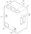
- FIG. 10 is a view showing the appearance of the beverage supply apparatus of the present invention.
- FIG. 11 is a view showing the internal configuration of the beverage supply device of the present invention.
- FIG. 12 is a view for explaining the operation of dropping the filling to the lower side by pressing the capsule of the pressing portion of the present invention.
- 14 to 18 are views for explaining the configuration of the mixing means constituting the beverage supply device of the present invention.
- 19 is a view showing a state in which carbon gas is supplied after water is supplied into the mixing means of the beverage supply device of the present invention.
- FIG. 20 is a view when the temperature control unit for adjusting the temperature of the water is configured in the beverage supply device of the present invention.
- FIG. 21 is a view for explaining an operation of discharging a capsule from which filling is discharged according to an embodiment of the present invention.
- FIG. 1 and 2 is a partial configuration of the device showing the process of dropping the filling by pressing the capsule used in the beverage supply device of the present invention
- Figure 3 is a user of the capsule used in the beverage supply device of the present invention Shows leaking charge directly.
- the capsule 10 is fixed to a fixing portion 40 having a hole sized to pass a portion of one side of the capsule 10, the capsule 10 is disposed on both sides of the capsule 10
- the first and second pressurizing portions 20 and 30 capable of pressing the side surfaces thereof) are configured.
- the capsule 10 receives the pressing force in a direction perpendicular to the length direction.
- an air layer 2 is formed above the capsule 10, and a liquid or solid filler 1 is positioned below the air layer 2. Therefore, when a force applied from the left and right sides is applied, leakage of the filling through the lower side rather than the upper side of the capsule 10 is made.
- the filling is leaked in the downward direction, even when the upper and lower sides of the capsule 10 are changed to stand, and the air layer 2 is still positioned above the inside of the capsule. Because of this, leakage in the downward direction can still be made.
- FIG. 3 the case where the user uses the pressing member 60 for leaking the filling 1 contained in the capsule 10 is illustrated.
- the pressing member 60 configured to be in contact with both sides of the capsule body 101, because the user presses both sides of the upper side of the capsule 10, when the upper side of the capsule 10 is opened Can be prevented.
- the user can leak the filling 1 contained in the capsule 10 to the lower side to be easily mixed with water or carbonated water.
- FIGS. 4 to 9 are views showing various examples of capsules used in the beverage supply device of the present invention.
- the capsule 10 of the present embodiment has a structure in which the filling 1 is accommodated in the capsule body 101 formed integrally. In the 101, not all of the filler 1 is filled, so that some air layer 2 is formed.
- the capsule body 101 is formed in a shape extending in the upper and lower directions, the first protrusion 102a and the second protrusion 102b protruding a predetermined length on each of the upper side and the lower side of the capsule body 101. Is formed.
- the filler 1 may be a concentrated liquid of a concentrated coffee juice or vitamin powder, or may be a powder or solid of coffee or vegetables / fruits or pharmaceutical ingredients.
- the filler 1 may be a raw coffee or coffee powder, a high concentrate or a powder of vegetables or fruits, or a liquid medicine or a powder medicine used in a pharmacy or a hospital.
- the thicknesses of the protrusions formed on the upper and lower sides while being integrally formed with the capsule body 101 are shown to be the same as the thickness of the capsule body 101, the pressure is gradually compressed by the force applied from the left and right sides to the lower direction.
- the thickness of the first protrusion 102a and the second protrusion 102b may be smaller than that of the capsule body 101.
- first and second protrusions may be formed along the outer circumferential surface of the capsule body 101, or may be formed at upper and lower ends of the capsule body 101.
- the first protrusion 102a, the second protrusion 102b, and the third protrusion 102c are formed on the outer circumferential surface of the capsule body 101, and these protrusions are integrally formed with each other.
- a protrusion strip having a predetermined thickness may be formed on the outer circumferential surface of the capsule body 101.
- the first and second protrusions 102a and 102b may be formed so as to be divided into upper and lower ends of the capsule body 101, respectively. . That is, the first protrusion and the second protrusion may be formed separately at the upper end and the lower end of the capsule body 101, and in the case of the second embodiment, the filler is positioned in the lower side of the capsule body 101. The air layer is located above.
- a soft member 160 having a relatively lower durability than the capsule body 101 may be formed. That is, the soft member 160 formed in the protrusion is made of a material that is easily broken or broken by a pressurized force.
- the capsule 10 of the present invention is more easily broken by the upper and lower portions by the force pushed in the direction perpendicular to the longitudinal direction and leakage of the filling. can do.
- the air layer 2 is positioned above the capsule, and when the user presses the upper part of the capsule, the filling may leak out to the lower side of the capsule. none.
- the longitudinal direction of the capsule 10 When the longitudinal direction of the capsule 10 is erected to be perpendicular to the horizontal plane, and gradually pressurizes both sides, only the lower portion of the capsule 10 may be torn and the filling may leak only downward.
- the capsule 10 of the fourth embodiment has an elliptical body having a cross section, a first case 110 for forming a receiving space of the filling 1 to be accommodated, and a second And a case 120.
- the first case 110 and the second case 120 is formed in the same shape, or in accordance with an embodiment of any one case to reduce the contact area of the first case 110 and the second case 120
- the contact surface can be formed smaller.
- the first and second cases have a thickness of both ends smaller than the thickness of the center portion, and when pressed in a direction perpendicular to the longitudinal direction of the capsule 10, the thin thickness of both ends is broken. Allow tearing to occur.
- the lower end of the capsule 10 is torn
- the filling of the filling by the opening of the lower end is made.
- a part of both ends of the first and second cases 110 and 120 is formed of the soft members 160 and 170.
- end portions of the first and second cases 110 and 120 are formed to have a thickness thinner than that of the center / body, and a part of both ends (upper and lower ends) is made of a soft material, and both sides of the capsule 10 are formed. Filling leakage can be made easier when pressurized.
- the configuration of the device for providing a drink in detail and for the convenience of description will be described a configuration for supplying a drink using the capsule of the first embodiment. .
- FIG. 10 is a view showing the appearance of the beverage supply apparatus of the present invention.
- the beverage supply device 200 of the present invention includes a capsule container in which at least one kind of capsules are accommodated, and includes at least one upper cover 204, 205, and 206 for opening an upper side of the capsule container.
- a beverage discharge part 209 is formed in which the filling in the capsule is mixed with water or carbon gas and carbonated water and discharged.
- the beverage supply device 200 is provided with a user inlet 207 that can be directly mounted to the capsule.
- the beverage supply device 200 When the user directly positions the capsule in the fixing part 40 through the user inlet 207, the beverage supply device 200 operates first so that the filling included in the capsule directly placed by the user becomes a beverage.
- one side of the beverage supply device 200 of the present invention may be provided with a water storage unit 202 for storing water, and a carbonated water storage unit 203 for storing carbonated water, the user directly water or carbonated water remains While checking the amount, the bottled water or carbonated water can be replaced / supplemented.
- the beverage supply device 200 of the present invention is connected to the water purifier, it is also possible to receive water directly from the outside.
- a water bottle which is easy to replace, such as a bottle of water, and a carbonated water bottle containing carbonated water are used.
- the carbonated water storage unit 203 may store carbonated water in which water and carbon gas are mixed in advance, but carbon gas that may be mixed with water in the water storage unit 202 may be stored.
- water may be supplied to the mixing means first, and then carbon dioxide may be formed by supplying carbon gas into the water.
- water is first supplied into the mixing means 240, and carbon dioxide is also formed by supplying carbon gas through the mixing nozzle.
- carbon gas is supplied through the mixing nozzle.
- the beverage supply device of the present invention is configured with a button unit that allows the user to select the desired beverage, the type of capsule is determined according to the type of beverage selected by the user, only water is mixed or water and carbon gas according to the corresponding beverage The carbonated water of is mixed.
- FIG. 11 is a view showing the internal configuration of the beverage supply device of the present invention.
- first to third storage containers 211, 212 and 213 for storing a plurality of capsules are disposed at an upper side, and a portion of a lower surface of each storage container 211, 212 and 213 is opened.
- Each of the open portions is connected to first to third supply tubes 221, 222, and 223 which provide a path of movement of the capsule.
- fixing parts 231, 232, and 233 for fixing the position of the falling capsule are connected to the first to third supply tubes.
- the lower surface of any one of the first to third containers is opened, and the capsule in the container is moved downward along the supply tube through the open portion.
- the capsule 10 is formed in a shape extending in one direction, the supply tube guides the capsule to fall in the vertical direction so that its position is fixed in the vertical direction (vertical direction) in the fixing portion (231,232,233).
- the user can directly position the desired capsule in the fourth fixing portion 234 through the user inlet 207, in this case, the pressing means 300 for pressing both sides of the capsule is a fourth high
- the movement and pressing operation of the capsule seated on the government 234 is preferentially performed.
- a pressurizing means 300 having a pressurizing part movable in at least two directions is configured, and the pressurizing means 300 includes a pair of pressurizing parts 20 and 30 and the pressurizing parts. It includes a pressure driving unit 310 to move in a direction closer or farther from each other or to be variable in length.
- the pressurizing part 20, 30 of the pressurizing means 300 moves the capsule 10 seated on the first to fourth fixing parts 231, 232, 233, and 234 above the input part 241 of the mixing means 240, In that state, both sides of the capsule 10 are pressurized so that the filling falls toward the inlet 241.
- the pressing means 300 will be described in more detail with reference to the drawings.
- FIG. 12 is a view for explaining the operation of dropping the filling to the lower side by pressing the capsule of the pressing portion of the present invention.
- the capsule 10 is seated on the first fixing part 231, and the first and second pressing parts 20 and 30 move the capsule 10 to the first fixing part 231.
- the case of shifting the position from is shown.
- the first and second pressing parts 20 and 30 grip the capsule 10 seated on the first fixing part 231 with a predetermined force, and then an upper side of the input part 241 of the mixing means 240. Move to. In addition, the first and second pressurizing portions 20 and 30 are moved in a direction in which the distance between them is narrowed to press both sides of the capsule 10, and a filling material through the lower end of the capsule 10. It leaks.
- the pressing means 300 moves a pair of pressing portions 20 and 30, the pressing portions in a first direction (X-axis direction) and in a second direction (Y-axis direction).
- a pressure driver 310 including a drive unit and a rail, such as a motor.
- the pressing parts 20 and 30 are configured to be movable in a second direction, for example, the Y-axis direction, so that the pressing parts 20 and 30 may be operated to decrease or move away from each other.
- the pressurized capsule 10 may be pressed to leak the filling material.
- the pressing parts 20 and 30 are configured to move a predetermined distance in the first direction, for example, the X-axis direction, so that the capsule 10 seated on the fixed part is inserted into the mixing means 240. 241 can be moved upward.
- the pressing means 300 to move the capsule 10
- the filling is taken out to the collection box 500 (see Fig. 21) Is further performed.
- the pressing means 300 presseurizes the capsule 10 for a predetermined time or for a time that can be set by the user
- the pressing means 300 moves the capsule in one direction by pressing down the volume.
- the capsule is used to move up the collection box 500 for collecting the used capsule.
- the pressing means 300 stops the pressing operation on the capsule, that is, when the pressing portions are separated from the capsule, the used capsule falls into the collection box 500. By this operation, the user can easily process the used capsule.
- 14 to 18 are views for explaining the configuration of the mixing means constituting the beverage supply device of the present invention.
- the mixing means 240 of the present embodiment forms a body and a mixing body 242 in which the filling of the capsule is mixed with water or carbon gas and carbonated water therein, and the mixing body ( 242 is formed on the upper side of the inlet 241 for introducing the filling of the capsule, the lower portion formed in the water or carbon gas, carbonated water and the filling, that is, the beverage discharge portion 245 for discharging the beverage, and A first inclined surface 243 and a second inclined surface 244 which form a lower portion of the mixing body 242 and are inclined at a predetermined angle are included.
- a first mixing nozzle 251 and a second mixing nozzle 252 are connected to both sides of the mixing body 242, each of the mixing nozzles and the first connecting pipe (251a, 252a) is supplied with water, Second connecting pipes 251b and 252b to which carbonated water or carbon gas is supplied are connected.
- Each of the first and second connectors may be connected to the water reservoir 202 and the carbonated water reservoir 203, and the second connectors 251b and 252b may be stored in the carbonated water reservoir 203 or the carbon gas.
- a gas reservoir or a hose that supplies carbon gas To a gas reservoir or a hose that supplies carbon gas.
- Carbon gas may be supplied through the second connecting pipes 251b and 252b, and in this case, water is first supplied through the first connecting pipes 251a and 252a and then the second connecting pipe 251b. 252b), so that the water contained in the mixing means is carbonated water.
- the first and second connectors are formed on both sides of the mixing body 242 of the mixing means, so that the water from the first connectors 251a and 252a on both sides of the mixing body 242.
- Carbonated water or carbon gas may be supplied through the second connecting pipes 251b and 252b at both sides of the mixing body 242. Since water, carbonated water, or carbon gas is supplied from both sides of the mixing body 242, rapid mixing with the filler may be achieved.
- a first opening and closing portion 245a for selectively opening and closing the beverage discharging portion 245 is formed on the first inclined surface 243 below the mixing body 242, and the mixing body is formed on the second inclined surface 244.
- a second opening and closing portion 246a for selectively opening and closing the washing water discharge portion 246 through which the washing water after washing the inside is moved is configured.
- the first opening and closing part 245a is opened.
- the beverage may exit through the beverage discharge part 245.
- water or carbonated water is supplied into the mixing body 242 through the first and second mixing nozzles 251 and 252.
- the pressing operation of the capsule by the pressing means is made, and the vitamin high concentrate or vitamin powder powder in the capsule is introduced into the mixing body 242 through the inlet 241.
- the mixing body 242 In a state where water or carbonated water is filled to some extent in the mixing body 242, a filling of liquid or solid flows in, so that the mixing time can be shortened.
- filling the inside of the mixing body 242 with water or carbonated water before pressurizing the capsule 10 to introduce the filling into the capsule body 242 does not fill all of the required amount of water or carbonated water, You may want to fill only a small amount.
- the inside of the mixing body 242 is filled with water or carbonated water, and leakage of the filling by the pressing means is caused.
- water or carbonated water may be further supplied through the first and second mixing nozzles 251 and 252 so as to reach a preset amount of water or carbonated water, and to fill the required amount of water or carbonated water.
- only carbon gas may be sprayed through the mixing nozzle to better mix the contents.
- the mixing tubes connected to the mixing nozzles 251 and 252 may be provided with water or carbonated water in order to allow the introduced filling to be mixed more effectively.
- a plurality of injection holes are formed to be injected in a plurality of directions.
- each of the first mixing nozzle 251 and the second mixing nozzle 252 is connected to the first mixing tube 261 and the second mixing tube, one side of which is open, and the mixing The tubes are formed with injection holes 261a having various injection angles.
- the mixing body 242 is supplied with a portion of water or carbonated water according to the type of beverage selected by the user.
- the first opening and closing portion 245a opens the inlet of the beverage discharging portion 245 and the mixed beverage is The beverage is supplied to the user through the discharge unit 245.
- water is supplied into the mixing body 242 through the first and second mixing nozzles 251 and 252, and the supplied water is provided in different directions through the injection holes 261 a of the mixing tube 261.
- the inner wall surfaces of the mixing body 242 are cleaned.
- the first and second opening and closing portions 245a and 246a are kept closed.
- the second opening / closing part 246a is opened to allow the washing product to exit through the washing water discharge part 246.
- the washing water discharge unit 246 may be connected to the drain hose connected to the beverage supply device of the present invention.
- 19 is a view showing a state in which carbon gas is supplied after water is supplied into the mixing means of the beverage supply device of the present invention.
- the mixing means 240 of the present invention is supplied with water supplied through the first connecting pipes 251a and 252a according to the type of beverage, or the second connecting pipes 251b and 252b together with the water. Carbon gas supplied through) may also be supplied.
- the carbon gas should be supplied in a state where water is contained in the mixing means 240, and a large number of bubbles 11 will be generated in the water by the supply of the carbon gas.
- the carbon gas may be supplied while the filling is dropped while water is supplied into the mixing means 240.
- FIG. 20 is a view when the temperature control unit for adjusting the temperature of the water is configured in the beverage supply device of the present invention.
- the user may want a hot drink.
- the temperature controller 400 connected to each of the first connecting pipes 251a and 252a may be used.
- the water supplied into the mixing means 240 may be heated.
- the temperature control unit 400 is a device that can control the water temperature, such as heating the water, or cooling the water, it can be operated in various ways depending on the type of beverage selected by the user.
- the present invention can provide beverages that can be consumed in various places as well as hospitals and pharmacies, there is industrial applicability thereof.
Landscapes
- Engineering & Computer Science (AREA)
- Food Science & Technology (AREA)
- Devices For Dispensing Beverages (AREA)
Abstract
본 발명의 음료 공급 장치는, 일체로 형성되고, 상하 방향으로 연장 형성되는 캡슐 바디와, 상기 캡슐 바디 내에 수용되고, 액체 또는 고체로 이루어진 충전물과, 상기 캡슐 바디 내에서 상기 충전물이 차지하는 공간 이외의 공간에 형성된 공기층으로 이루어지고, 상기 캡슐 바디의 상측 단부와 하측 단부에는 상기 캡슐 바디와 일체로 형성되면서 소정 길이 돌출 형성된 제 1 돌출부 및 제 2 돌출부가 구성되는 캡슐을 이용한 음료 공급 장치이다.
Description
본 발명은 음료 공급 장치에 대한 것으로서, 캡슐 내에 포함된 충전물을 배출시키기 위하여 상기 캡슐을 가압하여 내용물인 충전물을 물 또는 탄소나 탄산수 에 섞는 음료 공급 장치에 대한 것이다.
일반적으로 알려진 바와 같이, 발포정이라 함은 물에 녹여서 녹인 약물을 마시도록 하는 것을 말하며, 대표적인 것으로는 비타민이나 철분 등의 보급제, 제산제, 진통제, 감기약 등으로서 복용시에 물에 용해시켜 수제로 복용하도록 되어 있다.
이와 같은 발포정은 각종 기능이 첨가된 상태에서 이미 오래전에 개발되어 널리 이용되고 있으며, 그 사용처 또한 광범위하다.
한편, 최근에는 발포정에 각종 기능을 첨가한 상태에서 제작하여 식품 성분이 갖는 생체 방어, 생체 리듬의 조절, 질병의 예방과 회복 등 생체에 대하여 생체 조절 기능을 충분히 발휘할 수 있도록 하거나, 아이들의 성장 발육을 촉진하거나, 성별 또는 연령대별로 필요한 각종 필수 영양소 등을 섭취시키기 위하여 의학적으로 설계 및 개발된 발포정이 시판되고 있다.
그러나, 이러한 발포정의 경우, 사용자가 물에 발포정을 집어넣은 다음, 수분 동안 발포정이 물에 완전히 녹는 시간을 기다려야 하며, 이러한 사용상의 불편함 때문에 그 이용률이 저하되는 문제가 있다.
기존의 발포비타민과 같은 발포정은 물에 혼합되어 반응되는 도중에 나트륨이 반드시 발생하게 된다.
즉, 발포비타민에 포함된 탄산수소나트륨(NaHCO3)이 물과 반응하여, 탄산나트륨(Na2CO3)이 발생하는데, 건강을 위하여 먹는 음료에 나트륨이 많이 포함되어 있어, 오히려 건강을 해칠 수 있는 문제가 발생될 수 있다. 따라서, 발포비타민과 같은 영양제 및 음료 등을 물이나 탄소(탄소 기체) 또는 탄산수에 섞어 마실 수 있는 기호 식품을 사용자가 간단하고도, 건강하게 즐길 수 있는 방안이 필요하다.
본 발명의 장치는 캡슐에 포함된 액체 또는 고체의 충전물을 사용자가 쉽게 물이나 탄소, 탄산수 등을 이용하여 섞어 마실 수 있도록 하는 장치를 제안하고자 한다.
특히, 본 발명의 장치에 사용되는 캡슐은 세로로 세운 상태에서 가압하는 경우에, 하측으로만 충전물이 누출되는 구조로 이루어져, 물이나 탄소, 탄산수를 이용하여 쉽게 섞을 수 있는 장치를 제안하고자 한다.
또한, 다양한 종류의 고농축액 또는 분말 가루를 선택적으로 물이나 탄산수 또는 탄소 가스가 포함된 액체에 섞을 수 있으며, 이전 사용한 충전물이 혼합통 내에 남아있는 것을 방지하기 위하여, 혼합통 내부의 세척도 가능한 장치를 제안하고자 한다.
본 발명의 음료 공급 장치는, 일체로 형성되고, 상하 방향으로 연장 형성되는 캡슐 바디와, 상기 캡슐 바디 내에 수용되고, 액체 또는 고체로 이루어진 충전물과, 상기 캡슐 바디 내에서 상기 충전물이 차지하는 공간 이외의 공간에 형성된 공기층으로 이루어지고, 상기 캡슐 바디의 상측 단부와 하측 단부에는 상기 캡슐 바디와 일체로 형성되면서 소정 길이 돌출 형성된 제 1 돌출부 및 제 2 돌출부가 구성되는 캡슐을 이용한 음료 공급 장치이다.
제안되는 바와 같은 본 발명의 음료 공급 장치에 의해서, 사용자는 빠른 시간 내에 물이나 탄산수에 혼합된 커피나 비타민 음료를 섭취할 수 있으며, 혼합 바디 내부를 세척할 수 있는 공정을 형성함으로써, 다양한 음료를 제공하는 장치에서 서로 다른 종류의 음료가 혼합되는 것을 미연에 방지할 수 있는 장점이 있다.
도 1과 도 2는 본 발명의 음료 공급 장치에 사용되는 캡슐을 가압하여 충전물을 하측으로 떨어뜨리는 과정을 보여주는 장치의 일부 구성 도면이다.
도 3은 본 발명의 음료 공급 장치에 사용되는 캡슐을 사용자가 직접 충전물을 누출시키는 것을 보여주는 도면이다.
도 4 내지 도 9는 본 발명의 음료 공급 장치에 사용되는 캡슐들의 다양한 예를 보여주는 도면이다.
도 10은 본 발명의 음료 공급 장치의 외관을 보여주는 도면이다.
도 11은 본 발명의 음료 공급 장치의 내부 구성을 보여주는 도면이다.
도 12는 본 발명의 가압부를 캡슐을 가압하여 충전물을 하측으로 떨어트리는 동작을 설명하기 위한 도면이다.
도 13은 본 발명의 음료 공급 장치에 구성되는 가압 수단을 설명하기 위한 도면이다.
도 14 내지 도 18은 본 발명의 음료 공급 장치를 구성하는 혼합 수단의 구성을 설명하기 위한 도면들이다.
도 19는 본 발명의 음료 공급 장치의 혼합 수단 내에 물이 공급된 다음 탄소 기체가 공급되는 모습을 보여주는 도면이다.
도 20은 본 발명의 음료 공급 장치에 물의 온도를 조절하기 위한 온도 조절부가 구성되는 경우의 도면이다.
도 21은 본 발명의 실시예에 따라 충전물이 배출된 캡슐을 배출시키는 동작을 설명하기 위한 도면이다.
도 1과 도 2는 본 발명의 음료 공급 장치에 사용되는 캡슐을 가압하여 충전물을 하측으로 떨어뜨리는 과정을 보여주는 장치의 일부 구성 도면이고, 도 3은 본 발명의 음료 공급 장치에 사용되는 캡슐을 사용자가 직접 충전물을 누출시키는 것을 보여주는 도면이다.
먼저, 도 1 및 도 2를 참조하면, 본 발명의 음료 공급 장치에서 캡슐 내의 충전물을 누출시키는 과정이 도시되어 있다. 본 발명의 음료 공급 장치에서는, 실시예의 캡슐을 세로 방향으로 두고, 양측면 또는 단부를 가압하게 되면, 하측에 위치한 부위가 개방되어 충전물이 누출되는 기술을 이용한다.
도시된 바와 같이, 캡슐(10)의 일측 일부가 통과할 수 있는 크기의 홀을 갖는 고정부(40)에 상기 캡슐(10)이 고정되고, 상기 캡슐(10) 양측에 배치되어 상기 캡슐(10)의 측면을 가압할 수 있는 제 1 및 제 2 가압부(20,30)가 구성된다.
즉, 상기 제 1 및 제 2 가압부(20,30)가 상기 캡슐(10)의 몸체 측방향으로 가압하는 경우, 상기 캡슐(10)은 길이 방향에 대하여 수직한 방향으로 가압력을 전달받게 된다.
이때, 상기 캡슐(10) 내부에는 공기층(2)이 상측에 형성되고, 그 공기층(2) 하측에 액체 또는 고체의 충전물(1)이 위치하게 된다. 따라서, 좌우측에서 가압되는 힘이 가해지게 되면, 캡슐(10)의 상측이 아닌 하측을 통한 충전물의 누출이 이루어진다.
이와 같이, 본 발명의 캡슐(10)에서는 하측 방향으로 충전물이 누출되도록 하는데, 상기 캡슐(10)의 상측과 하측을 변경하여 세우는 경우에도, 상기 공기층(2)이 여전히 캡슐 내부에서 상측에 위치하기 때문에, 여전히 하측 방향으로의 누출이 이루어질 수 있다.
한편, 도 3의 경우에는, 간편하게 사용자가 캡슐(10) 내에 수용된 충전물(1)을 누출시키기 위한 가압 부재(60)를 이용하는 경우가 도시되어 있다. 캡슐 바디(101)의 양측면에 접촉할 수 있는 형상으로 구성된 가압 부재(60)를 이용하는 경우에, 캡슐(10)의 상측의 양측면을 사용자가 가압하기 때문에, 캡슐(10)의 상측부가 개방되는 경우를 방지할 수 있다.
이러한 가압 부재(60)를 이용하는 경우에, 사용자는 캡슐(10) 내에 수용된 충전물(1)을 하측으로 누출시켜서 물이나 탄산수에 쉽게 혼합시킬 수 있다.
도 4 내지 도 9는 본 발명의 음료 공급 장치에 사용되는 캡슐들의 다양한 예를 보여주는 도면이다.
먼저, 도 4 및 도 5를 참조하여, 제 1 실시예의 캡슐을 설명하면, 본 실시예의 캡슐(10)은 일체로 형성된 캡슐 바디(101) 내에 충전물(1)이 수용되는 구조이며, 상기 캡슐 바디(101) 내에는 상기 충전물(1)이 모두 채워지지 않아 일부 공기층(2)이 형성된다.
특히, 상기 캡슐 바디(101)는 상하측 방향으로 연장되는 형상으로 이루어지고, 상기 캡슐 바디(101)의 상측과 하측 각각에는 소정 길이 돌출 형성된 제 1 돌출부(102a)와, 제 2 돌출부(102b)가 형성된다.
그리고, 상기 충전물(1)은 고농축의 커피 원액 또는 비타민 분말이 농축된 액체가 되거나, 커피나 야채/과일 또는 제약 성분의 분말 가루 또는 고체가 될 수 있다. 예를 들어, 상기 충전물(1)은 커피 원액 또는 커피 가루가 되거나, 야채나 과일의 고농축액 또는 분말 가루가 되거나, 약국이나 병원에서 사용되는 액체약 또는 가루약 등 다양하게 적용될 수 있다.
도면에는 상기 캡슐 바디(101)와 일체로 형성되면서 상하 측에 각각 형성된 돌출부들의 두께가 상기 캡슐 바디(101)의 두께와 동일한 것처럼 도시되어 있지만, 좌우측에서 가압되는 힘에 의하여 서서히 압축되면서 하측 방향으로 충전물(1)이 보다 쉽게 누출되도록 하기 위하여 상기 제 1 돌출부(102a)와 제 2 돌출부(102b)의 두께는 상기 캡슐 바디(101) 보다 작게 형성될 수 있다.
한편, 상기 제 1 및 제 2 돌출부는 상기 캡슐 바디(101) 외주면을 따라 연속되도록 형성되거나, 캡슐 바디(101)의 상측 단부와 하측 단부에 형성될 수 있다.
즉, 도 5에 도시된 바와 같이, 상기 캡슐 바디(101) 외주면에는 상기 제 1 돌출부(102a), 제 2 돌출부(102b) 및 제 3 돌출부(102c)가 형성되고, 이들 돌출부들은 상호 일체로 형성되어, 상기 캡슐 바디(101)의 외주면에 소정 두께의 돌출 띠가 형성될 수 있다.
또한, 제 2 실시예로는, 도 6에 도시된 바와 같이, 상기 제 1 및 제 2 돌출부(102a,102b)는 상기 캡슐 바디(101)의 상측 단부와 하측 단부에 각각 구분되도록 형성될 수도 있다. 즉, 상기 제 1 돌출부와 제 2 돌출부는 캡슐 바디(101)의 상측 단부와 하측 단부에 각각 별개로 형성될 수 있으며, 제 2 실시예의 경우에도, 캡슐 바디(101) 내에는 하측에 충전물이 위치하고, 그 상측에는 공기층이 위치한다.
도 7 내지 도 9를 참조하여 본 발명의 캡슐의 제 3 실시예 내지 제 5 실시예를 설명하여 본다.
도 7을 참조하면, 제 3 실시예의 캡슐(10) 상측과 하측에 형성되는 돌출부(102a,102b) 내에 캡슐 바디(101) 보다 내구성이 상대적으로 약한 연질 부재(160)가 형성될 수 있다. 즉, 상기 돌출부 내에 형성되는 연질 부재(160)는 가압되는 힘에 의하여 파손되거나 부서지는 것이 용이한 재질로 이루어진다.
이러한 연질 부재(160)가 돌출부 내에 구성된 경우에는, 본 발명의 캡슐(10)은 길이 방향에 수직한 방향으로 가압되는 힘에 의하여 상측과 하측부위가 찢어짐/파손되어 충전물이 누출되는 것을 보다 용이하게 할 수 있다. 그리고, 앞서 설명한 바와 같이, 캡슐(10)을 세워서 양측면을 가압하게 되면, 공기층(2)이 캡슐 상측에 위치하고, 사용자가 캡슐의 상측 부위를 가압하게 되면, 충전물은 캡슐의 하측으로 누출될 수 밖에 없다.
캡슐(10)의 길이 방향이 수평면과 수직한 방향이 되도록 세우고, 양측면을 서서히 가압하게 되면, 캡슐(10)의 하측 부위만이 찢어져서 충전물이 하측으로만 누출될 수 있다.
도 8을 참조하면, 제 4 실시예의 캡슐(10)은 그 단면이 타원 형상의 본체로 이루어지고, 수용하고자 하는 충전물(1)의 수용 공간을 형성하기 위한 제 1 케이스(110)와, 제 2 케이스(120)를 포함한다.
상기 제 1 케이스(110)와 제 2 케이스(120)는 동일한 형상으로 이루어지거나, 실시예에 따라서는 제 1 케이스(110)와 제 2 케이스(120)의 접촉면적을 줄이기 위하여 어느 하나의 케이스의 접촉면이 더 작게 형성될 수 있다.
상기 제 1 및 제 2 케이스는 양측 단부의 두께가 중심부의 두께보다 더 적은 크기로 이루어져, 상기 캡슐(10)의 길이 방향에 대하여 수직한 방향으로 가압하는 경우에, 양측 단부의 얇은 두께쪽이 파손/찢어짐이 발생되도록 한다.
즉, 상기 캡슐(10)의 길이 방향이 수평면과 수직한 방향이 되도록, 세로로 세우고, 상기 캡슐(10)의 좌측면과 우측면을 가압하는 경우에, 상기 캡슐(10)의 하측 단부가 찢어질 수 있으며, 본 발명에서는, 상기 캡슐(10)을 세로로 위치시킨 상태에서 좌우측을 가압하는 경우에 하측 단부의 개방에 의한 충전물의 누출이 이루어지도록 한다.
도 9를 참조하면, 제 5 실시예의 캡슐(10)은 제 1 및 제 2 케이스(110,120)의 양측 단부 일부가 연질 부재(160,170)로 이루어지는 경우이다.
이 경우, 상기 제 1 및 제 2 케이스(110,120)의 단부는 중심부/몸체보다 얇은 두께로 이루어지면서, 양단(상측단, 하측단) 일부가 연질 재질로 이루어지는 경우이며, 캡슐(10)의 양측면을 가압하는 경우에 보다 용이하게 하측으로의 충전물 누출이 이루어질 수 있다.
위와 같이, 다양하게 구성될 수 있는 캡슐을 이용하여, 음료를 제공하는 장치의 구성에 대해서 상세히 설명하며, 설명의 편의를 위하여 제 1 실시예의 캡슐을 이용하여 음료를 공급하는 구성을 설명하기로 한다.
도 10은 본 발명의 음료 공급 장치의 외관을 보여주는 도면이다.
도 10을 참조하면, 본 발명의 음료 공급 장치(200)는 적어도 한 종류의 이상의 캡슐들이 수용되는 캡슐통이 위치하는데, 상기 캡슐통의 상측을 개방하기 위한 적어도 하나 이상의 상측 커버(204,205,206)가 구성되고, 전면에는 캡슐 내의 충전물이 물 또는 탄소 기체, 탄산수와 혼합되어 배출되는 음료 배출부(209)가 구성된다.
또한, 음료 공급 장치(200)에는 미리 준비된 캡슐 이외에 다른 캡슐을 사용자가 마시고자 하는 경우에, 직접 해당 캡슐을 장착할 수 있는 사용자 투입구(207)가 형성된다.
상기 사용자 투입구(207)를 통하여 사용자가 직접 캡슐을 고정부(40)에 위치시킨 경우에는, 상기 음료 공급 장치(200)는 사용자가 직접 위치시킨 캡슐에 포함된 충전물이 음료가 되도록 우선 동작한다.
또한, 본 발명의 음료 공급 장치(200)의 일측에는 물을 저장하는 물 저장부(202)와, 탄산수가 저장되는 탄산수 저장부(203)가 마련될 수 있으며, 사용자는 직접 물이나 탄산수가 남아있는 양을 확인하면서, 페트병 형태의 물이나 탄산수를 교체/보충할 수 있다.
다만, 실시예에 따라서는, 본 발명의 음료 공급 장치(200)가 정수기와 연결되어, 물을 외부에서 직접 공급받는 것도 가능하다. 도면에는, 생수통과 같이 교체하기가 편리한 물통과, 탄산수가 들어있는 탄산수통을 사용하는 경우가 예시되어 있다.
또한, 상기 탄산수 저장부(203)는 물과 탄소 기체가 미리 혼합되어 있는 탄산수가 저장될 수도 있지만, 상기 물 저장부(202)의 물과 추후에 혼합될 수 있는 탄소 기체가 저장될 수 있다. 이 경우, 혼합 수단에는 물이 먼저 공급된 다음, 물 내부로 탄소 기체를 공급함으로써 탄산수가 형성되도록 할 수 있다.
그리고, 본 발명의 실시예에 의하면, 혼합 수단(240) 내부로 물이 먼저 공급되고, 혼합 노즐을 통하여 탄소 기체를 공급함으로써, 탄산수가 형성되도록 구성하는 것 역시 가능하다. 후술하겠지만, 충전물이 비타민이 고농축된 액상으로 구성되는 경우에, 상기 혼합 수단(240) 내에 물이 먼저 공급된 다음, 탄소 기체가 공급되면서 상기 충전물이 혼합되도록 할 수 있다. 이 경우, 물 내로 탄소 기체가 다양한 방향으로 공급되므로, 충전물을 신속히 혼합하는데 소요되는 시간도 함께 줄일 수 있는 장점이 있다.
또한, 본 발명의 음료 공급 장치에는 사용자가 원하는 음료를 선택할 수 있는 버튼부가 구성되며, 사용자가 선택하는 음료의 종류에 따라 캡슐의 종류가 결정될 뿐만 아니라, 해당 음료에 따라 물만 혼합되거나 물과 탄소 기체의 탄산수가 혼합된다.
도 11은 본 발명의 음료 공급 장치의 내부 구성을 보여주는 도면이다.
도 11을 참조하면, 본 발명의 음료 공급 장치(200)는, 다수의 캡슐을 보관하는 제 1 내지 제 3 보관통(211,212,213)이 상측에 배치되고, 각각의 보관통(211,212,213)의 하부면 일부는 개방되어 있으며, 그 개방된 부위 각각은 캡슐의 이동 경로를 제공하는 제 1 내지 제 3 공급 튜브(221,222,223)들이 연결된다.
그리고, 상기 제 1 내지 제 3 공급 튜브들에는 낙하하는 캡슐의 위치를 고정시키기 위한 고정부들(231,232,233)이 연결된다.
사용자가 마시고자 하는 종류의 음료를 선택하게 되면, 제 1 내지 제 3 보관통 중 어느 하나의 하부면이 개방되고, 개방된 부위를 통하여 해당 보관통 내의 캡슐이 상기 공급 튜브를 따라 하측으로 이동하게 된다. 이때, 상기 캡슐(10)은 일방향으로 연장되는 형상으로 이루어지고, 상기 공급 튜브는 상기 고정부(231,232,233)에서 상하방향(세로 방향)으로 그 위치가 고정되도록 캡슐이 세로 방향으로 낙하하도록 가이드한다.
또한, 전술한 바와 같이, 사용자 투입구(207)를 통하여 사용자가 직접 제 4 고정부(234)에 원하는 캡슐을 위치시킬 수 있으며, 이때, 캡슐의 양측면을 가압하는 가압 수단(300)은 제 4 고정부(234)에 안착된 캡슐의 이동 및 가압 동작을 우선적으로 수행한다.
음료 공급 장치(200) 내에는 적어도 2방향으로 이동이 가능한 가압부를 갖는 가압 수단(300)이 구성되고, 상기 가압 수단(300)은 한 쌍의 가압부(20,30)와, 상기 가압부들이 서로 가까워지거나 멀어지는 방향으로 이동이 가능하도록 하거나 그 길이가 가변될 수 있도록 하는 가압 구동부(310)를 포함한다.
상기 가압 수단(300)의 가압부(20,30)는 상기 제 1 내지 제 4 고정부(231,232,233,234)에 안착된 캡슐(10)을 혼합 수단(240)의 투입부(241) 상측으로 이동시키고, 그 상태에서 캡슐(10)의 양측면을 가압하여 충전물이 상기 투입부(241)쪽으로 떨어지도록 한다. 상기 가압 수단(300)에 대해서는 도면과 함께 더 자세히 설명하기로 한다.
도 12는 본 발명의 가압부를 캡슐을 가압하여 충전물을 하측으로 떨어트리는 동작을 설명하기 위한 도면이다.
도 12를 참조하면, 제 1 고정부(231)에 캡슐(10)이 안착되고, 상기 제 1 및 제 2 가압부(20,30)가 상기 캡슐(10)을 상기 제 1 고정부(231)로부터 위치 이동시킨 경우가 도시되어 있다.
상기 제 1 및 제 2 가압부(20,30)는 상기 제 1 고정부(231)에 안착된 캡슐(10)을 소정 힘으로 그립한 다음, 상기 혼합수단(240)의 투입부(241) 상측으로 이동시킨다. 그리고, 상기 제 1 및 제 2 가압부(20,30)는 상호간의 간격이 좁아지는 방향으로 이동되어, 상기 캡슐(10)의 양측면을 가압하게 되고, 상기 캡슐(10)의 하측 단부를 통하여 충전물이 누출된다.
도 13은 본 발명의 음료 공급 장치에 구성되는 가압 수단을 설명하기 위한 도면이다.
도 13을 참조하면, 본 실시예의 가압 수단(300)은 한쌍의 가압부(20,30)와, 상기 가압부들을 제 1 방향(X축 방향)과, 제 2 방향(Y축 방향)으로 이동이 가능하도록 모터와 같은 구동부와 레일 등을 포함하는 가압 구동부(310)를 포함한다.
도시된 바와 같이, 상기 가압부들(20,30)은 제 2 방향, 예를 들면, Y축 방향으로 이동이 가능하도록 구성되어, 상호간의 간격이 줄어들거나 멀어지도록 운전될 수 있다. 상기 가압부들이 상호간에 간격이 좁아지는 경우에는, 내측에 수용된 캡슐(10)을 가압시켜 충전물을 누출시키는 경우가 된다.
또한, 상기 가압부들(20,30)은 제 1 방향, 예를 들면, X축 방향으로 소정 거리 이동이 가능하도록 구성되어, 고정부에 안착된 캡슐(10)을 혼합 수단(240)의 투입부(241) 상측으로 이동시키는 것이 가능하다.
그리고, 상기 캡슐(10) 내에 수용된 충전물을 혼합 수단(240)으로 떨어트린 다음에는, 상기 가압 수단(300)은 충전물이 빠져나간 캡슐(10)을 수거 박스(500, 도 21 참조)로 이동시키기 위한 동작이 더 수행된다. 도 21을 참조하면, 상기 가압 수단(300)은 기설정된 시간 또는 사용자가 설정해 둘 수 있는 시간 동안 캡슐(10)을 가압하는 동작이 수행된 다음에는, 가압되어 부피가 줄어든 캡슐을 어느 일방향으로 이동시키는데, 사용된 캡슐을 수거하기 위한 수거 박스(500) 상측으로 이동시킨다.
그 다음, 상기 가압 수단(300)은 캡슐에 대한 가압 동작을 중단시키면, 즉, 캡슐로부터 가압부들이 멀어지면 사용된 캡슐은 수거 박스(500)로 떨어지게 된다. 이와 같은 동작에 의하여, 사용자는 사용된 캡슐을 간편히 처리할 수 있게 된다.
도 14 내지 도 18은 본 발명의 음료 공급 장치를 구성하는 혼합 수단의 구성을 설명하기 위한 도면들이다.
먼저, 도 14 및 도 15를 참조하면, 본 실시예의 혼합 수단(240)은 몸체를 형성하고 내부에서 캡슐의 충전물이 물 또는 탄소 기체, 탄산수와 혼합되는 혼합 바디(242)와, 상기 혼합 바디(242)의 상측에 형성되어 캡슐의 충전물이 유입되도록 하는 투입구(241)와, 하측에 형성되어 물 또는 탄소 기체, 탄산수와 혼합된 충전물, 즉, 음료가 토출되는 음료 토출부(245)와, 상기 혼합 바디(242)의 하부를 형성하고 기설정된 각도로 기울어진 제 1 경사면(243)과 제 2 경사면(244)을 포함한다.
또한, 상기 혼합 바디(242)의 양측에는 제 1 혼합 노즐(251)과 제 2 혼합 노즐(252)이 연결되고, 각각의 혼합 노즐들은 물이 공급되는 제 1 연결관(251a, 252a)과, 탄산수 또는 탄소 기체가 공급되는 제 2 연결관(251b, 252b)이 연결된다. 상기 제 1 및 제 2 연결관 각각은 물 저장부(202) 및 탄산수 저장부(203)에 연결될 수 있으며, 제 2 연결관들(251b,252b)은 탄산수 저장부(203) 또는 탄소 기체가 저정된 기체 보관통이나 탄소 기체를 공급하는 호스에 연결될 수 있다.
상기 제 2 연결관들(251b, 252b)을 통하여 탄소 기체가 공급될 수 있으며, 이 경우, 상기 제 1 연결관(251a, 252a)을 통하여 물이 먼저 공급된 다음, 상기 제 2 연결관(251b, 252b)을 통한 탄소 기체를 공급함으로써, 혼합 수단 내에서 수용되었던 물이 탄산수가 되도록 한다.
그리고, 본 발명의 실시예에서는, 혼합 수단의 혼합 바디(242) 양측에 제 1 및 제 2 연결관 각각이 구성됨으로써, 혼합 바디(242) 양측에서 제 1 연결관(251a, 252a)들로부터 물이 공급되거나, 혼합 바디(242) 양측에서 제 2 연결관(251b, 252b)을 통하여 탄산수나 탄소 기체가 공급될 수 있다. 혼합 바디(242) 양측에서 물이나 탄산수 또는 탄소 기체가 공급되므로 충전물과의 신속한 혼합이 이루어질 수 있다.
또한, 상기 혼합 바디(242)의 하부의 제 1 경사면(243)에는 상기 음료 토출부(245)를 선택적으로 개폐시키기 위한 제 1 개폐부(245a)가 형성되고, 제 2 경사면(244)에는 혼합 바디(242) 내부를 세척한 후의 세척물이 이동되는 세척수 토출부(246)를 선택적으로 개폐시키기 위한 제 2 개폐부(246a)가 구성된다.
따라서, 상기 혼합 바디(242) 내부에서 캡슐 내에 수용된 액체 또는 고체의 충전물을 물 또는 탄소 기체, 탄산수와 혼합하여 사용자가 마실 수 있는 상태로 혼합된 다음에는, 상기 제 1 개폐부(245a)를 오픈시켜 음료가 상기 음료 토출부(245)를 통하여 빠져나갈 수 있다.
즉, 도 15에 도시된 바와 같이, 캡슐의 양측면을 가압하여 캡슐 하측 단부를 통하여 충전물이 누출되면, 상기 투입구(241)를 통하여 충전물이 혼합 바디(242) 내로 유입되는데, 본 발명에 따르면, 상기 캡슐(10)을 양측 방향에서 가압하기 전에, 상기 혼합 바디(242) 내에 물 또는 탄산수를 공급하는 동작이 선행된다. 사용자가 비타민 음료를 선택한 경우에는, 비타민 고농축액이 포함된 캡슐이 고정부로 안착되고, 가압 수단에 의하여 해당 캡슐은 상기 투입구(241)로 이동된다.
그리고, 상기 혼합 바디(242) 내부에는 상기 제 1 및 제 2 혼합 노즐(251,252)을 통하여 물 또는 탄산수가 공급된다.
그 다음, 상기 가압 수단에 의한 캡슐의 가압 동작이 이루어지고, 캡슐 내의 비타민 고농축액 또는 비타민 분말 가루는 상기 투입구(241)를 통하여 혼합 바디(242) 내부로 유입된다. 혼합 바디(242) 내에 물이나 탄산수가 어느 정도 채워진 상태에서, 액체 또는 고체의 충전물이 유입되므로, 그 혼합 시간을 단축할 수 있다.
다만, 상기 캡슐(10)을 가압하여 충전물을 캡슐 바디(242) 내부로 유입시키기 전에, 혼합 바디(242) 내부를 물이나 탄산수로 채우는 것은, 필요로 하는 물이나 탄산수 양 전부를 채우는 것이 아니라, 일부양만 채우도록 할 수 있다.
왜냐하면, 캡슐의 충전물이 혼합 바디(242)의 측벽이나 바닥면에 직접 닿아 혼합에 어려움을 겪지 않도록 하기 위하여, 혼합 바디(242) 내부를 물이나 탄산수로 채우는 것이며, 상기 가압 수단에 의한 충전물의 누출이 완료된 다음에는, 물이나 탄산수의 미리 설정된 양에 도달하도록, 상기 제 1 및 제 2 혼합 노즐(251,252)을 통하여 물이나 탄산수가 더 공급될 수 있으며, 필요로 하는 양 전부를 채운 물이나 탄산수에 캡슐과 충전물이 떨어진 후 탄소 기체만 혼합 노즐을 통하여 분사함으로써 내용물이 더 잘 섞이도록 할 수 있다.
상기 혼합 노즐(251,252)을 통하여 혼합 바디(242)내로 물이나 탄산수가 공급되는 도중에, 유입된 충전물이 더욱 효과적으로 혼합되도록 하기 위하여, 상기 혼합 노즐들(251,252)에 연결된 혼합 튜브들에는 물이나 탄산수가 다수의 방향으로 분사되도록 하는 분사홀이 복수개 형성된다.
즉, 도 18에 도시된 바와 같이, 제 1 혼합 노즐(251)과 제 2 혼합 노즐(252) 각각은 일측이 개방된 제 1 혼합 튜브(261)와, 제 2 혼합 튜브와 연결되고, 상기 혼합 튜브들에는 분사각도가 다양하게 구성된 분사홀(261a)들이 형성된다.
본 발명에 따르면, 캡슐 내의 충전물이 혼합 바디로 떨어지기 전에, 혼합 바디(242) 내부에는 사용자가 선택한 음료의 종류에 따라 물 또는 탄산수 일부양이 공급된다.
그리고, 가압 수단에 의한 캡슐의 가압 동작이 완료된 다음에는, 사용자가 선택한 음료의 종류에 따라 필요로 하는 물 또는 탄소 기체, 탄산수의 양에 도달하도록 물 또는 탄소 기체, 탄산수의 추가 공급이 이루어지는데, 혼합 튜브에 분사홀을 통하여 공급되는 물 또는 탄소 기체, 탄산수에 의하여 충전물이 신속히 혼합될 수 있다.
충전물을 물 또는 탄소 기체, 탄산수 또는 다른 액체와의 혼합이 완료된 다음에는, 도 16에 도시된 바와 같이, 제 1 개폐부(245a)가 상기 음료 토출부(245)의 입구를 개방시키고, 혼합 음료는 상기 음료 토출부(245)를 통하여 사용자에게 공급된다.
반면, 상기 혼합 바디(242) 내에서 음료의 혼합이 이루어진 다음에, 사용자가 다른 종류의 캡슐을 선택하는 경우에는, 상기 혼합 바디(242) 내부에 남아있는 충전물 또는 음료를 세척하기 위하여, 상기 혼합 바디(242) 내부를 세척하는 공정이 수행된다.
이때, 상기 혼합 바디(242) 내부로는 상기 제 1 및 제 2 혼합 노즐(251,252)을 통하여 물이 공급되고, 공급되는 물은 혼합 튜브(261)의 분사홀(261a)을 통하여 서로 다른 방향으로 분사됨으로써, 혼합 바디(242)의 내벽면들을 세척하게 된다. 물론, 이러한 세척 공정에서는, 상기 제 1 및 제 2 개폐부(245a,246a)는 닫혀진 상태로 유지된다.
이러한 세척 공정이 수행된 다음에는, 도 17에 도시된 바와 같이, 상기 제 2 개폐부(246a)가 오픈되어 세정물이 상기 세척수 토출부(246)를 통하여 빠져나가도록 한다. 상기 세척수 토출부(246)는 본 발명의 음료 공급 장치에 연결되는 배수용 호스에 연결될 수 있다.
도 19는 본 발명의 음료 공급 장치의 혼합 수단 내에 물이 공급된 다음 탄소 기체가 공급되는 모습을 보여주는 도면이다.
앞서 설명한 바와 같이, 본 발명의 혼합 수단(240)에는 음료의 종류에 따라 상기 제 1 연결관(251a, 252a)을 통해서 공급되는 물이 공급되거나, 상기 물과 함께 제 2 연결관(251b, 252b)을 통해서 공급되는 탄소 기체도 공급될 수 있다.
이때, 상기 탄소 기체는 상기 혼합 수단(240) 내에 물이 수용된 상태에서 공급되어야 하며, 상기 탄소 기체의 공급에 의하여 물 내부에는 많은 수의 기포(11)들이 발생할 것이다.
상기 충전물이 보다 빠르게 혼합되도록 하기 위하여, 상기 혼합 수단(240) 내에 물이 공급된 상태에서, 충전물이 떨어지도록 하면서 상기 탄소 기체가 공급될 수 있다.
도 20은 본 발명의 음료 공급 장치에 물의 온도를 조절하기 위한 온도 조절부가 구성되는 경우의 도면이다.
도 20을 참조하면, 본 발명의 캡슐 내에 커피 농축액이 수용된 경우, 사용자는 뜨거운 음료를 원하는 경우가 있으며, 이 경우, 상기 제 1 연결관(251a, 252a) 각각에 연결된 온도 조절부(400)에 의하여 혼합 수단(240) 내부로 공급되는 물이 가열될 수 있다.
상기 온도 조절부(400)는 물을 가열하거나, 물을 냉각하는 등의 물 온도를 조절할 수 있는 장치로서, 사용자가 선택한 음료의 종류에 따라 다양하게 동작할 수 있다.
본 발명은 병원이나 약국 뿐만 아니라 다양한 장소에서 마실 수 있는 음료를 제공할 수 있기 때문에, 그 산업상 이용 가능성이 있다.
Claims (7)
- 일체로 형성되고, 상하 방향으로 연장 형성되는 캡슐 바디와, 상기 캡슐 바디 내에 수용되고, 액체 또는 고체로 이루어진 충전물과, 상기 캡슐 바디 내에서 상기 충전물이 차지하는 공간 이외의 공간에 형성된 공기층으로 이루어지고, 상기 캡슐 바디의 상측 단부와 하측 단부에는 상기 캡슐 바디와 일체로 형성되면서 소정 길이 돌출 형성된 제 1 돌출부 및 제 2 돌출부가 구성되는 캡슐을 이용한 음료 공급 장치로서,상기 캡슐의 종류에 따라 보관될 수 있도록 하는 적어도 하나 이상의 보관통과,상기 보관통 각각에 연결되어 상기 캡슐이 이동되도록 경로를 제공하는 적어도 하나 이상의 공급 튜브와,상기 공급 튜브 각각을 통하여 빠져나오는 상기 캡슐을 지지하기 위한 적어도 하나 이상의 고정부와,상기 고정부에 안착된 상기 캡슐의 양측면을 가압함으로써, 상기 캡슐 내의 충전물이 배출되도록 하는 가압 수단과,상기 가압 수단에 의하여 상기 캡슐의 하측으로부터 누출되는 충전물과, 물 또는 탄산수 또는 탄소 기체를 혼합하는 혼합 수단을 포함하는 음료 공급 장치.
- 제 1 항에 있어서,상기 혼합 수단은,상기 충전물이 유입되도록 일부가 개방된 투입구와,상기 충전물을 물 또는 탄산수 또는 탄소 기체가 혼합되는 공간을 제공하는 혼합 바디와,상기 혼합 바디 내부로 상기의 물 또는 탄산수 또는 탄소 기체를 공급하기 위하여 상기 혼합 바디에 연결되는 혼합 노즐과,상기 혼합 노즐과 연결되고, 상기 혼합 바디 내에 배치되는 혼합 튜브를 포함하는 음료 공급 장치.
- 제 2 항에 있어서,상기 혼합 튜브에는 상기 물 또는 탄소 기체 또는 탄산수를 복수의 방향으로 분사시키기 위하여 서로 다른 방향으로 형성된 복수 개의 분사홀이 형성되는 음료 공급 장치.
- 제 2 항에 있어서,상기 혼합 노즐은 상기 혼합 바디의 양측에 각각 결합되는 제 1 혼합 노즐과 제 2 혼합 노즐을 포함하고,상기 제 1 혼합 노즐 및 제 2 혼합 노즐 각각은 물이 공급되는 제 1 연결관과, 탄산수 또는 탄소 기체가 공급되는 제 2 연결관에 연결되는 음료 공급 장치.
- 제 4 항에 있어서,상기 혼합 바디의 하부면은 제 1 경사면과 제 2 경사면으로 이루어지고,상기 제 1 경사면에는 상기 혼합 바디 내에서 혼합된 음료가 배출되는 음료 토출부가 구성되고,상기 제 2 경사면에는 상기 혼합 바디 내부를 세척하는 동작이 수행된 후에 세척한 물이 배출되도록 하는 세척수 토출부가 연결되는 음료 공급 장치.
- 제 4 항에 있어서,상기 제 1 연결관과 제 2 연결관에는 각각 상기 혼합 수단 내부로 공급되는 물을 가열시킬 수 있는 온도 조절부가 구성되는 음료 공급 장치.
- 제 5 항에 있어서,상기 제 1 경사면에는 상기 음료 토출부를 선택적으로 개폐시키기 위한 제 1 개폐부가 형성되고,상기 제 2 경사면에는 상기 세척수 토출부를 선택적으로 개폐시키기 위한 제 2 개폐부가 구성되는 음료 공급 장치.
Applications Claiming Priority (2)
| Application Number | Priority Date | Filing Date | Title |
|---|---|---|---|
| KR10-2016-0036140 | 2016-03-25 | ||
| KR1020160036140A KR101835208B1 (ko) | 2016-03-25 | 2016-03-25 | 음료 공급 장치 |
Publications (1)
| Publication Number | Publication Date |
|---|---|
| WO2017164634A1 true WO2017164634A1 (ko) | 2017-09-28 |
Family
ID=59900533
Family Applications (1)
| Application Number | Title | Priority Date | Filing Date |
|---|---|---|---|
| PCT/KR2017/003044 Ceased WO2017164634A1 (ko) | 2016-03-25 | 2017-03-22 | 음료 공급 장치 |
Country Status (2)
| Country | Link |
|---|---|
| KR (1) | KR101835208B1 (ko) |
| WO (1) | WO2017164634A1 (ko) |
Families Citing this family (3)
| Publication number | Priority date | Publication date | Assignee | Title |
|---|---|---|---|---|
| KR102218826B1 (ko) * | 2019-10-21 | 2021-02-23 | (주)메디프레소 | 듀얼 음료 추출장치 |
| WO2021080090A1 (ko) * | 2019-10-21 | 2021-04-29 | (주)메디프레소 | 캡슐 음료 추출장치 및 이의 제어방법 |
| KR102224062B1 (ko) * | 2019-11-19 | 2021-03-09 | (주)메디프레소 | 캡슐 음료 추출장치의 제어방법 |
Citations (5)
| Publication number | Priority date | Publication date | Assignee | Title |
|---|---|---|---|---|
| KR20100064716A (ko) * | 2008-12-05 | 2010-06-15 | 주식회사 텐텐투 | 캡슐을 이용한 음료추출장치 |
| JP2011224242A (ja) * | 2010-04-22 | 2011-11-10 | Nishiyama Kogyo Kk | 飲料自動供給装置及び飲料自動供給装置の制御方法 |
| KR101344359B1 (ko) * | 2013-01-28 | 2013-12-23 | 계명대학교 산학협력단 | 캡슐음료 추출장치 |
| JP2014524320A (ja) * | 2011-08-25 | 2014-09-22 | ネステク ソシエテ アノニム | カートリッジ位置合わせシステム |
| WO2014181129A1 (en) * | 2013-05-09 | 2014-11-13 | Mars, Incorporated | Beverage preparation capsules |
-
2016
- 2016-03-25 KR KR1020160036140A patent/KR101835208B1/ko not_active Expired - Fee Related
-
2017
- 2017-03-22 WO PCT/KR2017/003044 patent/WO2017164634A1/ko not_active Ceased
Patent Citations (5)
| Publication number | Priority date | Publication date | Assignee | Title |
|---|---|---|---|---|
| KR20100064716A (ko) * | 2008-12-05 | 2010-06-15 | 주식회사 텐텐투 | 캡슐을 이용한 음료추출장치 |
| JP2011224242A (ja) * | 2010-04-22 | 2011-11-10 | Nishiyama Kogyo Kk | 飲料自動供給装置及び飲料自動供給装置の制御方法 |
| JP2014524320A (ja) * | 2011-08-25 | 2014-09-22 | ネステク ソシエテ アノニム | カートリッジ位置合わせシステム |
| KR101344359B1 (ko) * | 2013-01-28 | 2013-12-23 | 계명대학교 산학협력단 | 캡슐음료 추출장치 |
| WO2014181129A1 (en) * | 2013-05-09 | 2014-11-13 | Mars, Incorporated | Beverage preparation capsules |
Also Published As
| Publication number | Publication date |
|---|---|
| KR20170111194A (ko) | 2017-10-12 |
| KR101835208B1 (ko) | 2018-03-06 |
Similar Documents
| Publication | Publication Date | Title |
|---|---|---|
| WO2017164634A1 (ko) | 음료 공급 장치 | |
| KR100498727B1 (ko) | 개별호퍼를 구비한 자동약제 포장장치 | |
| JP2004203433A (ja) | 薬剤供給装置 | |
| EP2838814B1 (en) | Capsule and dispensing machine for beverages | |
| KR910004426A (ko) | 약제 포장기 | |
| KR20190000870A (ko) | 약제 인출 장치 | |
| NZ324630A (en) | Apparatus to be mounted on a container comprising a spout structure and a retention pocket containing a beneficial agent | |
| US20150050392A1 (en) | Method and system for providing drinks, drinks container and drinks device | |
| JP2004057296A (ja) | 液体バッグ、液体バッグ用口部材およびその製造方法 | |
| KR101716620B1 (ko) | 처방약 자동 포장 인출 장치 | |
| JP6624701B1 (ja) | 薬剤経口投与器具およびそれに適用される筒部材 | |
| JP6362112B2 (ja) | 薬剤手撒き装置 | |
| CN102920599A (zh) | 复剂型药剂瓶 | |
| WO2017160086A1 (ko) | 충전물을 포함하는 캡슐 | |
| KR101970960B1 (ko) | 약제 인출 장치 | |
| JP2003291901A (ja) | 薬剤供給装置 | |
| CN212416545U (zh) | 一种可分离储存和混合使用的滴液式胶囊 | |
| CN212118608U (zh) | 一种方便服药的药品分配装置 | |
| KR102355846B1 (ko) | 고액 분리형 용기마개 | |
| CN202207299U (zh) | 带定位推动装置的软瓶 | |
| CN221069160U (zh) | 一种药房片剂分发装置 | |
| CN213254271U (zh) | 一种挤料装置及染发剂配色装置 | |
| JP3868956B2 (ja) | 複室容器の弱シール部剥離器具 | |
| KR20190090172A (ko) | 가루약 분배 및 저장 장치 | |
| KR200250064Y1 (ko) | 약자동분포기의 수동분배용 트레이 |
Legal Events
| Date | Code | Title | Description |
|---|---|---|---|
| NENP | Non-entry into the national phase |
Ref country code: DE |
|
| 121 | Ep: the epo has been informed by wipo that ep was designated in this application |
Ref document number: 17770604 Country of ref document: EP Kind code of ref document: A1 |
|
| 32PN | Ep: public notification in the ep bulletin as address of the adressee cannot be established |
Free format text: NOTING OF LOSS OF RIGHTS PURSUANT TO RULE 112(1) EPC (EPO FORM 1205A DATED 30/11/2018) |
|
| 122 | Ep: pct application non-entry in european phase |
Ref document number: 17770604 Country of ref document: EP Kind code of ref document: A1 |