WO2017166256A1 - Procédé et dispositif de transmission de signal de référence, procédé et dispositif de réception de signal de référence, et système - Google Patents
Procédé et dispositif de transmission de signal de référence, procédé et dispositif de réception de signal de référence, et système Download PDFInfo
- Publication number
- WO2017166256A1 WO2017166256A1 PCT/CN2016/078228 CN2016078228W WO2017166256A1 WO 2017166256 A1 WO2017166256 A1 WO 2017166256A1 CN 2016078228 W CN2016078228 W CN 2016078228W WO 2017166256 A1 WO2017166256 A1 WO 2017166256A1
- Authority
- WO
- WIPO (PCT)
- Prior art keywords
- resource
- antenna ports
- csi
- reference signal
- map
- Prior art date
- Legal status (The legal status is an assumption and is not a legal conclusion. Google has not performed a legal analysis and makes no representation as to the accuracy of the status listed.)
- Ceased
Links
Images




Classifications
-
- H—ELECTRICITY
- H04—ELECTRIC COMMUNICATION TECHNIQUE
- H04L—TRANSMISSION OF DIGITAL INFORMATION, e.g. TELEGRAPHIC COMMUNICATION
- H04L5/00—Arrangements affording multiple use of the transmission path
- H04L5/003—Arrangements for allocating sub-channels of the transmission path
- H04L5/0048—Allocation of pilot signals, i.e. of signals known to the receiver
-
- H—ELECTRICITY
- H04—ELECTRIC COMMUNICATION TECHNIQUE
- H04B—TRANSMISSION
- H04B7/00—Radio transmission systems, i.e. using radiation field
- H04B7/02—Diversity systems; Multi-antenna system, i.e. transmission or reception using multiple antennas
- H04B7/04—Diversity systems; Multi-antenna system, i.e. transmission or reception using multiple antennas using two or more spaced independent antennas
- H04B7/0413—MIMO systems
-
- H—ELECTRICITY
- H04—ELECTRIC COMMUNICATION TECHNIQUE
- H04B—TRANSMISSION
- H04B7/00—Radio transmission systems, i.e. using radiation field
- H04B7/02—Diversity systems; Multi-antenna system, i.e. transmission or reception using multiple antennas
- H04B7/04—Diversity systems; Multi-antenna system, i.e. transmission or reception using multiple antennas using two or more spaced independent antennas
- H04B7/06—Diversity systems; Multi-antenna system, i.e. transmission or reception using multiple antennas using two or more spaced independent antennas at the transmitting station
- H04B7/0613—Diversity systems; Multi-antenna system, i.e. transmission or reception using multiple antennas using two or more spaced independent antennas at the transmitting station using simultaneous transmission
- H04B7/0684—Diversity systems; Multi-antenna system, i.e. transmission or reception using multiple antennas using two or more spaced independent antennas at the transmitting station using simultaneous transmission using different training sequences per antenna
-
- H—ELECTRICITY
- H04—ELECTRIC COMMUNICATION TECHNIQUE
- H04L—TRANSMISSION OF DIGITAL INFORMATION, e.g. TELEGRAPHIC COMMUNICATION
- H04L5/00—Arrangements affording multiple use of the transmission path
- H04L5/0001—Arrangements for dividing the transmission path
- H04L5/0014—Three-dimensional division
- H04L5/0023—Time-frequency-space
-
- H—ELECTRICITY
- H04—ELECTRIC COMMUNICATION TECHNIQUE
- H04L—TRANSMISSION OF DIGITAL INFORMATION, e.g. TELEGRAPHIC COMMUNICATION
- H04L5/00—Arrangements affording multiple use of the transmission path
- H04L5/003—Arrangements for allocating sub-channels of the transmission path
- H04L5/0048—Allocation of pilot signals, i.e. of signals known to the receiver
- H04L5/005—Allocation of pilot signals, i.e. of signals known to the receiver of common pilots, i.e. pilots destined for multiple users or terminals
-
- H—ELECTRICITY
- H04—ELECTRIC COMMUNICATION TECHNIQUE
- H04L—TRANSMISSION OF DIGITAL INFORMATION, e.g. TELEGRAPHIC COMMUNICATION
- H04L5/00—Arrangements affording multiple use of the transmission path
- H04L5/0091—Signalling for the administration of the divided path, e.g. signalling of configuration information
- H04L5/0094—Indication of how sub-channels of the path are allocated
-
- H—ELECTRICITY
- H04—ELECTRIC COMMUNICATION TECHNIQUE
- H04L—TRANSMISSION OF DIGITAL INFORMATION, e.g. TELEGRAPHIC COMMUNICATION
- H04L5/00—Arrangements affording multiple use of the transmission path
- H04L5/0001—Arrangements for dividing the transmission path
- H04L5/0003—Two-dimensional division
- H04L5/0005—Time-frequency
- H04L5/0007—Time-frequency the frequencies being orthogonal, e.g. OFDM(A) or DMT
Definitions
- the embodiments of the present invention relate to the field of communications, and in particular, to a reference signal sending method, a reference signal receiving method, an apparatus, and a system.
- reference signals there are different kinds of reference signals in the mobile communication system, such as reference signals for channel estimation and reference signals for channel state measurement.
- a Cell-specific Reference Signal is a reference signal for channel estimation on each resource unit. Supports the transmission of up to 4 antenna ports.
- the resource unit can be a physical resource block (PRB).
- DMRS Demodulation Reference Signal
- CSI-RS channel state information reference signal
- R12 of LTE the CSI-RS supports transmission of up to 16 antenna ports on each resource unit.
- the above several reference signals have different number of antenna ports supported in the LTE system, but only support the transmission of up to 16 antenna ports.
- reference signals are needed to support more antenna port numbers for better Multiple-Input Multiple-Output (MIMO) performance.
- MIMO Multiple-Input Multiple-Output
- the current reference signal transmission method is used for reference signal transmission, when the number of antenna ports is increased to 20, 24, 28 or 32 antenna ports, the reference signal needs to occupy a very large amount of radio resources on each resource unit, resulting in movement.
- the resource overhead of the communication system increases.
- the embodiment of the present invention provides a reference Signal transmitting method, reference signal receiving method, device and system.
- the technical solution is as follows:
- the present invention provides a method for transmitting a reference signal, where the method includes: a first resource map of a reference signal whose number of antenna ports is Z, where the first resource map includes the number of antenna ports.
- the reference signal of the Z is mapped to the time-frequency resource;
- the transmitting device maps the reference signal with the number of antenna ports Z to the target time-frequency resource according to the first resource map, and then sends the reference signal to the target time-frequency resource;
- the first resource map is repeated in a time domain and/or a frequency domain with K resource units as a repeating unit, where the K resource units are continuous in the time domain or continuous in the frequency domain in the reference signal resource set.
- the reference signal resource set is a time-frequency resource configured to transmit the reference signal
- a reference signal corresponding to the number of antenna ports is P in each of the K resource units a second resource map, wherein the G antenna ports of the P antenna ports corresponding to the second resource map of each two adjacent resource units are the same, and the H antenna ports are not present.
- Said P is a subset of antenna ports of said first resource map corresponding to antenna ports Z, P ⁇ Z.
- the transmitting device determines a first resource map of the reference signal with the number of antenna ports being Z, and then maps the reference signal with the antenna port Z to the target time-frequency resource according to the first resource map. Transmitting; since the first resource map is repeated in the time domain and/or the frequency domain with K resource units as a repeating unit, the reference signal number corresponding to the number of antenna ports in each of the K resource units is P.
- the two resource maps, and the G antenna ports of the P antenna ports corresponding to the second resource map of each adjacent two resource units are the same, and the H antenna ports are different, and the different resource units are different.
- the local repetition of the antenna port achieves the effect of reducing the amount of time-frequency resources occupied by the reference signal in each resource unit, while taking into account the transmission density of the reference signal.
- any two of the two resource mappings of the K resource units are corresponding to a single resource unit
- the time domain location occupied by the time-frequency resource pattern is the same; in the K resource units At least two of the second resource maps have different frequency domain positions occupied by a time-frequency resource pattern corresponding to a single resource unit, and/or at least two of the second resource resources are present in the K resource units.
- the map has the same frequency domain position occupied by the time-frequency resource pattern corresponding to a single resource unit.
- the i The jth third resource map in the resource unit and the jth third resource map in the i+1th resource unit occupy the same in the time-frequency resource pattern corresponding to the single resource unit a time domain location; the jth third resource map in the i th resource unit corresponds to a group of antenna ports in the M group antenna port, and the first one of the i+1th resource units
- the j third resource maps correspond to another group of antenna ports of the M group antenna ports; wherein 0 ⁇ i ⁇ K-1, 0 ⁇ j ⁇ N-1.
- the K resource units are at the reference signal The same time domain resource is occupied in the resource set, and the K resource units are consecutive in the frequency domain of the reference signal resource set; the jth third of each of the K resource units The resource map occupies the same time domain location in a single resource unit, and the Mth jth third resource maps of the M resource units are in one-to-one correspondence with the M group antenna ports; the K The j+1th third resource map in each resource unit in the resource unit occupies the same time domain position in a single resource unit, and there are M j+1th out of M resource units The third resource map corresponds to the M group antenna ports one by one; the jth third resource map in the same resource unit and the j+1th third resource map respectively correspond to each other; The antenna ports are different; wherein 0 ⁇ j ⁇ j+1 ⁇ N-1.
- the K resource units are in the reference signal The same frequency domain resource is occupied in the resource set, and the K resource units are consecutive in the time domain of the reference signal resource set; the jth third in each of the K resource units The resource map occupies the same time domain location in a single resource unit, and the jth third resource map in the M resource units has a one-to-one correspondence with the M group antenna ports; the K resource units The j+1th third resource map in each resource unit occupies the same time domain location in a single resource unit, and exists in M resource units The M th+1th third resource maps are in one-to-one correspondence with the M group antenna ports; the jth third resource map and the j+1 in the same resource unit The antenna ports corresponding to the third resource maps are different; wherein 0 ⁇ j ⁇ j+1 ⁇ N-1.
- the K resource units occupy the same frequency domain resource in the reference signal resource set, and the K resource units are in the reference signal resource set Continuous in the time domain.
- the K resource units occupy the same time domain resource in the reference signal resource set, and the K resource units are in the reference signal resource set The frequency domain is continuous.
- the resource unit is a PRB, or the resource unit is a PRB pair.
- the reference signal is a DMRS, a CSI-RS, or a CRS.
- the number of each group of the antenna ports of the M group antenna ports is partially continuous, and the number of the mth antenna port is p (m) is:
- the number of OFDM symbol pairs occupied by the N third resource maps in each of the resource units is three pairs Or 2 pairs or 1 pair.
- the reference signal is a CSI-RS
- the three third resource maps in each of the resource units occupy time-frequency resources indicated by CSI-RS configuration 0, CSI-RS configuration 1, and CSI-RS configuration 2 in five groups of CSI-RS configurations; Or, the three third resource maps in each of the resource units occupy the CSI-RS configuration 0, the CSI-RS configuration 2, and the CSI- in the five groups of CSI-RS configurations.
- the time-frequency resources indicated by the CSI-RS configuration 1, the CSI-RS configuration 3, and the CSI-RS configuration 4; the five groups of CSI-RS configurations include:
- k is a subcarrier label in the PRB pair
- l is an orthogonal frequency division multiplexing OFDM symbol label in the PRB pair.
- the N sets of antenna ports corresponding to the second resource map of the kth resource unit are the M group (k mod M)+ ⁇ group antenna port in the antenna port, ((k+1) mod M)+ ⁇ group antenna port, ..., ((k+N-1) mod M)+ ⁇ group antenna Port; wherein 0 ⁇ k ⁇ K-1, ⁇ is a predetermined offset value.
- the present invention provides a reference signal receiving method, the method comprising: receiving, by a device, a first resource map of a reference signal whose antenna port number is Z, where the first resource map includes the number of antenna ports a location at which the reference signal of the Z is mapped to a time-frequency resource; the receiving device receives, according to the first resource map, the reference signal whose number of antenna ports is Z from a target time-frequency resource; A resource map is repeated in a time domain and/or a frequency domain with K resource units as a repeating unit, wherein the K resource units are consecutive or consecutive K in the time domain in the reference signal resource set.
- the reference signal resource set is a time-frequency resource configured to transmit the reference signal
- a reference signal corresponding to the number of antenna ports is P in each of the K resource units a second resource map, wherein the G antenna ports of the P antenna ports corresponding to the second resource map of each adjacent two resource units are the same, and the H antenna ports are different.
- Said subset of antenna ports P is the resource map corresponding to the first antenna ports Z, P ⁇ Z.
- the receiving device determines a first resource map of the reference signal with the number of antenna ports being Z, and receives a reference signal of the antenna port Z from the target time-frequency resource according to the first resource map;
- the first resource map is repeated in the time domain and/or the frequency domain with K resource units as a repeating unit, and the second resource mapping of the reference signal corresponding to the number of antenna ports P in each of the K resource units.
- the G antenna ports of the P antenna ports corresponding to the second resource map of each adjacent two resource units are the same, and the H antenna ports are different, and the antenna ports of different resource units are used.
- the local repetition achieves the effect of reducing the amount of time-frequency resources occupied by the reference signal in each resource unit, while taking into account the transmission density of the reference signal.
- the present invention provides a transmitting apparatus, where the transmitting apparatus includes at least one unit, and the at least one unit is configured to implement the reference signal transmission provided by the foregoing first aspect or any one of the possible implementation manners of the first aspect. method.
- the present invention provides a receiving device, the receiving device comprising at least one unit, The at least one unit is configured to implement the reference signal receiving method provided by any one of the possible implementations of the second aspect or the second aspect.
- the present invention provides a transmitting device, the transmitting device comprising a processor, a memory and a transmitter connected to the processor, the processor for storing one or more instructions, the instruction being indicated as being
- the processor is configured to implement a reference signal sending method provided by any one of the foregoing first aspect or the first aspect, where the transmitter is configured to implement modulation and demodulation of a reference signal. send.
- the present invention provides a receiving device, the receiving device comprising a processor, a memory and a transmitter connected to the processor, the processor for storing one or more instructions, the instruction being indicated as being
- the processor is configured to implement a reference signal receiving method provided by any one of the foregoing second aspect or the second aspect, where the transmitter is configured to implement modulation and demodulation of a reference signal. receive.
- FIG. 1 is a schematic structural diagram of a reference signal transceiving system according to an embodiment of the present invention
- FIG. 2 is a schematic structural diagram of a sending device according to an embodiment of the present invention.
- FIG. 3 is a schematic structural diagram of a receiving device according to an embodiment of the present invention.
- FIG. 4 is a flowchart of a method for transmitting and receiving a reference signal according to an embodiment of the present invention
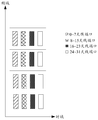
- FIG. 5 is a schematic diagram of distribution of K resource units according to an embodiment of the present invention.
- FIG. 6 is a partial schematic diagram of a first resource map provided by an embodiment of the present invention.
- FIG. 7 is a partial schematic diagram of a first resource map provided by an embodiment of the present invention.
- FIG. 8 is a partial schematic diagram of a first resource map provided by another embodiment of the present invention.
- FIG. 9 is a schematic diagram of distribution of K resource units according to another embodiment of the present invention.
- FIG. 10 is a schematic diagram of implementation of a method for transmitting and receiving a reference signal according to another embodiment of the present invention.
- FIG. 11 is a schematic diagram of implementation of a method for transmitting and receiving a reference signal according to another embodiment of the present invention.
- FIG. 12 is a schematic diagram of implementation of a method for transmitting and receiving a reference signal according to another embodiment of the present invention.
- FIG. 13 is a schematic diagram of a polarization direction of an antenna port according to an embodiment of the present invention.
- FIG. 14 is a schematic diagram of a polarization direction of an antenna port according to another embodiment of the present invention.
- 15 is a schematic diagram of resource elements that a CSI-RS can occupy in each resource unit
- 16A is a schematic diagram of a CSI-RS configuration manner of each group of 8 antenna ports
- 16B is a schematic diagram of a CSI-RS configuration manner of each group of 8 antenna ports
- 16C is a schematic diagram of a CSI-RS configuration manner of each group of 8 antenna ports
- 16D is a schematic diagram of a CSI-RS configuration manner of each group of 8 antenna ports
- 16E is a schematic diagram of a CSI-RS configuration manner of each group of 8 antenna ports
- 17 is a schematic diagram of implementation of a method for transmitting and receiving a reference signal according to an embodiment of the present invention.
- FIG. 18 is a schematic diagram of implementation of a method for transmitting and receiving a reference signal according to an embodiment of the present invention.
- FIG. 19 is a schematic diagram of implementation of a DMRS transceiving method according to an embodiment of the present invention.
- 20 is a schematic diagram of implementation of a DMRS transceiving method according to another embodiment of the present invention.
- Figure 21 is a block diagram showing the structure of a transmitting apparatus according to an embodiment of the present invention.
- FIG. 22 is a block diagram showing the structure of a receiving apparatus according to another embodiment of the present invention.
- a “module” as referred to herein refers to a program or instruction stored in a memory that is capable of implementing certain functions;
- "unit” as referred to herein refers to a functional structure that is logically divided, the “unit” may be Pure hardware implementation, or a combination of hardware and software.
- Multiple as referred to herein means two or more. "and/or”, describing the association relationship of the associated objects, indicating that there may be three relationships, for example, A and/or B, which may indicate that there are three cases where A exists separately, A and B exist at the same time, and B exists separately.
- the character "/" generally indicates that the contextual object is an "or" relationship.
- FIG. 1 is a schematic structural diagram of a reference signal transceiving system provided by an exemplary embodiment of the present invention.
- the reference signal transceiving system includes: a transmitting device 120 and a receiving device 140.
- the Transmitting device 120 has the capability to transmit a reference signal.
- the transmitting device 120 is an access network device in the mobile communication system.
- the access network device is a Global System for Mobile communication (GSM) or a base station (BTS, Base Transceiver Station) in Code Division Multiple Access (CDMA).
- GSM Global System for Mobile communication
- BTS Base Transceiver Station
- CDMA Code Division Multiple Access
- access network The device is a base station (NodeB) in UMTS.
- the access network device is an evolved base station (eNB or e-NodeB) in Long Term Evolution (LTE).
- eNB evolved base station
- LTE Long Term Evolution
- Receiving device 140 has the ability to receive reference signals.
- the receiving device 140 is a terminal device in the mobile communication system.
- the access device 140 may be a mobile station, a mobile station, a user terminal, a user device, or a user equipment (UE).
- UE user equipment
- mobile phones, tablets and smart home appliances For example: mobile phones, tablets and smart home appliances.
- the transmitting device 120 and the receiving device 140 communicate via a wireless carrier.
- a plurality of transmitting devices 120 may be included, and/or a plurality of receiving devices 140, and one receiving device 140 may communicate with a plurality of transmitting devices 120.
- a plurality of transmitting devices 120 may be included, and/or a plurality of receiving devices 140, and one receiving device 140 may communicate with a plurality of transmitting devices 120.
- FIG. 1 only one transmitting device 120 and one receiving device 140 are shown as an example, which is not limited in this embodiment.
- FIG. 2 is a schematic structural diagram of a transmitting device according to an exemplary embodiment of the present invention.
- the transmitting device includes a processor 21, a memory 22, and a transmitter 23.
- the processor 21 is connected to the memory 22.
- the processor 21 includes one or more processing cores, and the processor 21 executes various functional applications and information processing by running software programs and modules.
- Memory 22 can be used to store software programs as well as modules.
- the memory 22 can store the operating system 24, the application modules 25 required for at least one function.
- the application module 25 may include a determining module and a sending module.
- the determining module is configured to determine a first resource map of the reference signal with the number of antenna ports being Z
- the sending module is configured to set the number of the antenna ports to be Z according to the first resource map.
- the reference signal is mapped to the target time-frequency resource and then transmitted.
- memory 22 can be implemented by any type of volatile or non-volatile memory device, or a combination thereof, such as static random access memory (SRAM), electrically erasable programmable read only memory (EEPROM), erasable In addition to Programmable Read Only Memory (EPROM), Programmable Read Only Memory (PROM), Read Only Memory (ROM), Magnetic Memory, Flash Memory, Disk or Optical Disk.
- SRAM static random access memory
- EEPROM electrically erasable programmable read only memory
- EPROM Programmable Read Only Memory
- PROM Programmable Read Only Memory
- ROM Read Only Memory
- the transmitter 23 includes a modem module and a multiple input multiple output (MIMO) antenna, and the MIMO antenna is an antenna that supports multi-antenna port transceiving.
- the MIMO antenna includes at least two transmit antennas.
- the transmitter 23 is configured to implement modulation and demodulation and transmission of the reference signal.
- the processor 21 maps the reference signal with the number of antenna ports Z to the target according to the first resource map.
- the time-frequency resource is transmitted through the transmitter 23.
- Z is an integer greater than 2.
- the structure of the transmitting device 120 shown in FIG. 2 does not constitute a limitation on the transmitting device 120, and may include more or less components or some components in combination, or different. Assembly of parts.
- FIG. 3 is a schematic structural diagram of a receiving device 140 according to an exemplary embodiment of the present invention.
- the receiving device 140 includes a processor 31, a memory 32, and a receiver 33.
- the processor 31 is connected to the memory 32.
- the processor 31 includes one or more processing cores, and the processor 31 executes various functional applications and information processing by running software programs and modules.
- Memory 32 can be used to store software programs as well as modules.
- the memory 32 may also store an operating system 35, an application module 36 required for at least one function.
- the application module 36 may include a determining module and a receiving module; and a determining module, configured to determine a first resource map of the reference signal whose antenna port number is Z. And a receiving module, configured to receive, according to the first resource map, a reference signal with an antenna port number of Z from the target time-frequency resource.
- memory 32 can be implemented by any type of volatile or non-volatile storage device, or a combination thereof, such as static random access memory (SRAM), electrically erasable programmable read only memory (EEPROM), erasable In addition to Programmable Read Only Memory (EPROM), Programmable Read Only Memory (PROM), Read Only Memory (ROM), Magnetic Memory, Flash Memory, Disk or Optical Disk.
- SRAM static random access memory
- EEPROM electrically erasable programmable read only memory
- EPROM Programmable Read Only Memory
- PROM Programmable Read Only Memory
- ROM Read Only Memory
- Magnetic Memory Flash Memory
- Disk Disk
- Optical Disk Optical Disk
- the receiver 33 includes a modem module and a MIMO antenna, and the MIMO antenna is an antenna that supports multi-antenna port transceiving.
- the MIMO antenna includes at least two receiving antennas.
- the receiver 33 is configured to implement modulation and demodulation and reception of the reference signal.
- the processor 31 receives, by the receiver 33, a reference signal having the number of antenna ports Z from the target time-frequency resource according to the first resource map.
- Z is an integer greater than or equal to 4.
- the structure of the receiving device 140 shown in FIG. 3 does not constitute a limitation of the pair of receiving devices 140, and may include more or less components or some components in combination, or different. Assembly of parts.
- FIG. 4 shows a reference signal transceiver according to an exemplary embodiment of the present invention.
- Method flow chart of the law This embodiment is exemplified by the reference signal transmitting method applied to the transmitting device shown in FIG. 1.
- the reference signal transceiving method includes the following steps:
- Step 401 The transmitting device determines a first resource map of the reference signal whose number of antenna ports is Z.
- the first resource map includes a location where a reference signal with an antenna port number Z is mapped to a time-frequency resource.
- the transmitting device determines a first resource map of the reference signal with the number of antenna ports being Z according to a predetermined resource mapping rule.
- Step 402 The transmitting device maps the reference signal with the number of antenna ports Z to the target time-frequency resource according to the first resource map, and then sends the reference signal.
- the transmitting device maps the reference signal with the number of antenna ports Z to the target time-frequency resource according to the first resource mapping resource map, and performs some processing steps well known to those skilled in the art on the reference signal, such as: discretization, time domain preprocessing, and Fu The Fourier Transformation (FFT) transform, the frequency domain analysis, the filtering, the inverse Fourier transform (IFFT), and the like, after the processing of the reference signal is completed, the reference signal is transmitted.
- FFT Fourier Transformation
- Step 403 The receiving device determines a first resource map of the reference signal whose number of antenna ports is Z.
- the receiving device determines a first resource map of the reference signal with the number of antenna ports being Z according to a predetermined resource mapping rule.
- Step 404 The receiving device receives, from the target time-frequency resource, a reference signal with the number of antenna ports being Z according to the first resource mapping.
- the first resource map is repeated in the time domain and/or the frequency domain by using K resource units as a repeating unit, and the K resource units are consecutive K resources in the time domain or in the frequency domain in the reference signal resource set.
- the reference signal resource set is a time-frequency resource configured to transmit a reference signal
- a second resource map corresponding to the reference signal of the number of antenna ports P in each of the K resource units and each The G antenna ports of the P antenna ports corresponding to the second resource maps of the adjacent two resource units are the same, and the H antenna ports are different, and the P antenna ports are corresponding to the first resource map.
- the P antenna ports are true subsets of the Z antenna ports corresponding to the first resource map.
- Z is an integer greater than or equal to 4
- P is an integer greater than 2
- K is an integer greater than 2
- H is an integer greater than 2
- G is an integer greater than 2.
- steps 401 and 402 can be implemented separately as the side of the transmitting device side.
- steps 403 and 404 can be separately implemented as a method embodiment on the receiving device side.
- the transmitting device determines a first resource map of the reference signal with the number of antenna ports being Z, and then sets the antenna port as a reference signal of Z according to the first resource map.
- the receiving device After being mapped to the target time-frequency resource, the receiving device receives the reference signal with the number of antenna ports as Z from the target time-frequency resource according to the first resource map; since the first resource map is in the time domain and/or the frequency domain, K
- the resource units are repeated for the repeating unit, and the second resource map corresponding to the reference signal of the antenna port number P in each of the K resource units, and the second resource of each adjacent two resource units
- the G antenna ports in the P antenna ports corresponding to the map are the same, and the H antenna ports are different.
- the local repetition of the antenna ports in different resource units achieves the reduction of the reference signal in each resource unit.
- a resource unit is a time-frequency resource unit for carrying transmission data.
- the resource unit may be a physical resource block (PRB), a physical resource block pair (Physical Resource Block pair), a physical resource block group (RBG), or a virtual resource block (Virtul Resource). Block, VRB).
- PRB physical resource block
- RBG physical resource block group
- VRB virtual resource block
- one PRB pair includes 12 consecutive subcarriers in the frequency domain and 14 consecutive symbols in the time domain.
- the symbol is an Orthogonal Frequency Division Multiplexing (OFDM) symbol or a Single-carrier Frequency-Division Multiple Access (SC) of an LTE system in which the subcarrier is located at a frequency of 15 kHz.
- OFDM Orthogonal Frequency Division Multiplexing
- SC Single-carrier Frequency-Division Multiple Access
- the -FDMA) symbol, or symbol is the symbol of a communication system in which the frequency domain of one subcarrier is greater than 15 kHz.
- a PRB pair occupies a resource of a transmission time length in the time domain. In different LTE versions, the transmission time length may be any symbol from 1 symbol to 14 symbols.
- the resource unit is a PRB pair for schematic description.
- the first resource map is repeated in the frequency domain with K resource units as a repeating unit, and the K resource units occupy the same time domain resource in the reference signal resource set, and are in the frequency domain in the reference signal resource set. Consecutive K resource units.
- the first resource map is repeated in the time domain with K resource units as a repeating unit, and the K resource units occupy the same frequency domain resource in the reference signal resource set, and are in the time domain in the reference signal resource set. Consecutive K resource units.
- the first resource map is repeated in the time domain and the frequency domain with K resource groups as a repeating unit, and each resource group includes K resource units.
- K is an integer greater than 2.
- the K resource units occupy the same time domain resource in the reference signal resource set, and are consecutive in the frequency domain of the reference signal resource set, that is, the K resource units are evenly arranged in the frequency domain. There are no other subcarriers between two resource elements adjacent in the frequency domain, as shown in FIG. 5. Moreover, there are no other resource units between two resource elements adjacent in the frequency domain.
- the reference signal with the number of antenna ports is mapped to the target time domain according to the first resource map, and then the transmission is performed, that is, each K resource units in the first resource map corresponds to Z antenna ports.
- Y is an integer less than or equal to 8, such as Y is 2, 4, 8.
- Z is an integer greater than or equal to 4
- M is an integer greater than or equal to 2
- N is an integer greater than or equal to 2.
- the antenna ports corresponding to the reference signals transmitted by any two resource units are not identical; or any reference signal sent by any two resource units is At least there are different antenna ports corresponding to B*Y reference signals.
- H is an integer greater than 2
- G is an integer greater than 2
- A is an integer greater than or equal to 1
- B is an integer greater than or equal to 1.
- each set of third resource maps corresponds to one set of antenna ports of the M group antenna ports.
- the K resource units include K second resource maps, and each of the second resource maps includes N third resource maps.
- Z is an integer greater than or equal to 4
- K is an integer greater than 2
- M is an integer greater than or equal to 2
- N is an integer greater than or equal to 2.
- FIG. 6 is a partial schematic diagram corresponding to four resource units in a first resource map, where four resource units are numbered according to 0-3, and four resource units 0 to 3 correspond to four second resource maps.
- the resource unit 1 also includes three third resource maps, which correspond to 8 to 15 antenna ports, 16 to 23 antenna ports, and 24 to 31 antenna ports, respectively;
- resource unit 2 also includes The three third resource maps respectively correspond to 16 to 23 antenna ports, 24 to 31 antenna ports, and 0 to 7 antenna ports; and resource unit 3 also includes three third resource maps. Corresponding to 24 to 31 antenna ports, 0 to 7 antenna ports, and 8 to 15 antenna ports.
- the antenna ports corresponding to the 16 reference signals are the same, that is, the 8-15 antenna ports and the 16-23 antenna ports are the same; there are 8 reference signals corresponding to each other.
- the antenna ports are different. For example, 0 to 7 antenna ports and 24 to 31 antenna ports are different.
- the antenna ports corresponding to the reference signals transmitted by any two of the K resource units are also not identical.
- the antenna ports corresponding to the eight reference signals are different, that is, the 16 to 23 antenna ports are the same; there are 16 reference signals corresponding to each other.
- the antenna ports are different.
- 0 to 7 antenna ports are different from 8 to 15 antenna ports.
- the set of antenna ports in each second resource map corresponds to a third resource map.
- FIG. 6 there are four types of third resource maps, such as when the resource unit 3 is used to transmit 8 to 15 antenna ports.
- the frequency resource corresponds to a third resource map.
- the jth third resource map in the i th resource unit and the j th third resource map in the i+1th resource unit correspond to a single resource unit.
- the same time domain position is occupied in the time-frequency resource pattern;
- the jth third resource map in the i-th resource unit corresponds to one set of antenna ports in the M group antenna port, and the jth in the i+1th resource unit
- the third resource map corresponds to another set of antenna ports of the M group antenna ports.
- the number of resource units may be sorted from top to bottom in the frequency domain, or from bottom to top in the frequency domain, and may be sorted from left to right in the time domain, or sorted from right to left.
- the present invention The embodiment does not limit this.
- the order in the frequency domain is as follows.
- the number of the third resource map may be sorted from top to bottom in the frequency domain, or from bottom to top in the frequency domain, and may be sorted from left to right or right to left in the time domain. This embodiment of the present invention does not limit this, and the numbering rule adopted by the third resource map in each resource unit is the same.
- the jth third resource map and one of the antenna ports of the M group antenna port and the other antenna of the jth third resource map and the M group antenna port are not the same set of antenna ports.
- K is an integer greater than 2
- M is an integer greater than or equal to 2
- N is an integer greater than or equal to 2
- i and j are integers.
- the resource element 0 and the resource unit 1 adjacent to each other in the frequency domain are taken as an example, and the 0th group of the third resource map and the resource unit 1 located on the left side of the resource unit 0 are located on the left side.
- the three resource maps occupy the same time domain location and the same frequency domain location: the first third resource map in the middle of resource unit 0 and the first third resource map in the middle of resource unit 1 occupy the same Time domain location and the same frequency domain location; the third third resource map on the right side of resource unit 0 and the third third resource map on the right side of resource unit 1 occupy the same time domain location And the same frequency domain location. among them,
- the 0th third resource map on the left side of the resource unit 0 corresponds to the reference signal corresponding to the 0-7 antenna port, and the 0th group third resource map on the left side of the resource unit 1 corresponds to the 8-15 antenna port. Corresponding reference signal.
- the first third resource map in the middle of the resource unit 0 corresponds to the reference signal corresponding to the 8 to 15 antenna ports
- the first third resource map in the middle of the resource unit 1 corresponds to the 16 to 23 antenna ports. Reference signal.
- the second third resource map on the right side of the resource unit 0 corresponds to the reference signal corresponding to the 16 to 23 antenna ports
- the second third resource map on the right side of the resource unit 1 corresponds to the 24 to 31 antenna ports. Corresponding reference signal.
- FIG. 6 It can be seen from FIG. 6 that there are G antenna ports in the P antenna ports corresponding to the second resource map of each adjacent two resource units, and there are H antenna ports which are different, and antennas in different resource units are used.
- the local repetition of the port achieves the effect of reducing the amount of time-frequency resources occupied by the reference signal in each resource unit, while taking into account the transmission density of the reference signal.
- P is an integer greater than 2
- H is an integer greater than 2
- G is an integer greater than 2. number.
- FIG. 7 and FIG. 8 respectively show a non-invention embodiment corresponding to 32 antenna ports. Schematic diagram of the transmission of the reference signal.
- a reference signal corresponding to 32 antenna ports is transmitted in each resource unit, and the time-frequency resources that need to be occupied in each resource unit are 32 time-frequency resource units, and this The transmission density at time is 1, that is, the reference signal corresponding to each antenna port appears once in each resource unit.
- the reference signal corresponding to the 16 antenna ports is transmitted in each resource unit, and the antenna ports corresponding to the reference signals transmitted in the adjacent two resource units are completely different.
- the time-frequency resource that needs to be occupied in the resource unit is 16 time-frequency resource units, and the transmission density at this time is 0.5, that is, the reference signal corresponding to each antenna port appears once every two resource units.
- the time-frequency resource that needs to be occupied in each resource unit is 24 time-frequency resource units, and the transmission density at this time is 0.75, that is, the reference signal corresponding to each antenna port. , will appear 3 times in every 4 resource units. Therefore, the manner shown in FIG. 6 can reduce the amount of time-frequency resources occupied by the reference signals corresponding to all antenna ports in each resource unit, and at the same time balance the transmission density of the reference signals.
- FIG. 6 , FIG. 7 and FIG. 8 are only schematic descriptions, and are not specific to the number of the antenna ports.
- the K resource units occupy the same frequency domain resource in the reference signal resource set, and the K resource units are in the reference signal resource.
- the time domain of the set is continuous, that is, the K resource units are evenly arranged in the time domain, and the first symbol is not included between the two resource units adjacent in the time domain, and the first symbol is configured to send the reference.
- a symbol of a signal but a second symbol may be included between two adjacent resource elements in the time domain, and the second symbol is a symbol configured to transmit other signals than the reference signal, as shown in FIG. .
- each of the K resource units corresponds to Z antenna ports
- the Z antenna ports include M groups of antenna ports, and each group of antennas
- Y is an integer less than or equal to 8, such as Y is 2, 4, 8.
- a second resource map of a reference signal corresponding to the number of antenna ports in each of the K resource units, P ⁇ Z; the second resource map is obtained by aggregation of N third resource maps, P N*Y
- the antenna ports corresponding to the reference signals transmitted by any two resource units are not identical; or any reference signal sent by any two resource units is At least there are different antenna ports corresponding to B*Y reference signals.
- each third resource map corresponds to one of the M groups of antenna ports.
- the K resource units in the first resource map include K second resource maps, and each of the second resource maps includes N third resource maps.
- Z is an integer greater than or equal to 4
- K is an integer greater than 2
- M is an integer greater than or equal to 2
- N is an integer greater than or equal to 2
- P is an integer greater than 2
- H is an integer greater than 2.
- G is an integer greater than 2
- A is an integer greater than or equal to 1
- B is an integer greater than or equal to 1.
- FIG. 10 is a partial schematic diagram corresponding to K resource units in a first resource map, where four resource units are numbered according to 0-3, and four resource units 0 to 3 correspond to four second resource maps.
- the resource unit 1 also includes three third resource maps, which correspond to 8 to 15 antenna ports, 16 to 23 antenna ports, and 24 to 31 antenna ports, respectively;
- resource unit 2 also includes Three third resource maps corresponding to 16 to 23 antenna ports, 24 to 31 antenna ports, and 0 to 7 antenna ports respectively;
- resource unit 3 also includes three third resource maps, respectively corresponding to 24 to 31 antenna ports, 0 to 7 antenna ports, and 8 to 15 antenna ports.
- the antenna ports corresponding to the 16 reference signals are the same, that is, the 8-15 antenna ports and the 16-23 antenna ports are the same; there are 8 reference signals corresponding to each other.
- the antenna ports are different. For example, 0 to 7 antenna ports and 24 to 31 antenna ports are not. The same.
- the antenna ports corresponding to the reference signals transmitted by any two resource units are also not identical.
- the antenna ports corresponding to the eight reference signals are different, that is, the 16 to 23 antenna ports are the same; and the antenna ports corresponding to the 16 reference signals are different, for example, 0.
- the ⁇ 7 antenna port is different from the 8 to 15 antenna port.
- the jth third resource map in the i th resource unit and the j th third resource map in the i+1th resource unit correspond to a single resource unit.
- the same time domain position is occupied in the time-frequency resource pattern;
- the jth third resource map in the i-th resource unit corresponds to one set of antenna ports in the M group antenna port, and the jth in the i+1th resource unit
- the third resource map corresponds to another set of antenna ports of the M group antenna ports.
- the number of resource units may be sorted from top to bottom in the frequency domain, or from bottom to top in the frequency domain, and may be sorted from left to right in the time domain, or from right to left. This example does not limit this.
- the order in the frequency domain is as follows.
- the number of the third resource map may be sorted from top to bottom in the frequency domain, or from bottom to top in the frequency domain, and may be sorted from left to right or right to left in the time domain. This embodiment of the present invention does not limit this, and the numbering rule adopted by the third resource map in each resource unit is the same.
- the jth third resource map and one of the antenna ports of the M group antenna port and the other antenna of the jth third resource map and the M group antenna port are not the same set of antenna ports.
- Z is an integer greater than or equal to 4
- K is an integer greater than 2
- M is an integer greater than or equal to 2
- N is an integer greater than or equal to 2
- P is an integer greater than 2
- H is an integer greater than 2.
- G is an integer greater than 2
- A is an integer greater than or equal to 1
- B is an integer greater than or equal to 1
- i and j are integers.
- the number of the antenna port in FIG. 10 is only a schematic description, and is not a specific number of the antenna port, which is not limited in the embodiment of the present invention.
- the first resource map includes K repeating units in different time domain locations, and each repeating unit includes several resource units; each resource unit is in each repeating unit. The location is the same, as shown in Figure 11.
- a partial schematic diagram of a first mapping resource map is shown in FIG. 11, the partial schematic diagram including 1 weight A complex unit that includes 16 resource units.
- the four resource units belonging to the same time domain position in each repeating unit are used in the same manner or similar to the manner shown in FIG. 6 when transmitting the reference signal, and are not described herein again;
- the four resource units belonging to the same frequency domain location in the unit are used in the same or similar manner as the one shown in FIG. 10 when transmitting the reference signal, and are not described herein.
- the number of the antenna port in FIG. 11 is only a schematic description, and is not a specific number of the antenna port, which is not limited in this embodiment of the present invention.
- each third resource map occupies one OFDM symbol pair in the time domain, and the number of OFDM symbol pairs occupied by the three third resource maps in each resource unit is three pairs, and each resource is used.
- the number of OFDM symbol pairs occupied by the three third resource maps in the unit may also be two pairs or one pair.
- An OFDM symbol pair refers to two consecutive OFDM symbols, for example, the 5th OFDM symbol and the 6th OFDM symbol are one OFDM symbol pair.
- resource unit 0 transmits 3*8 reference signals, which respectively correspond to 0-7 antenna ports, 8-15 antenna ports, and 16-23 antenna ports;
- the resource unit 1 transmits 3*8 reference signals, which respectively correspond to 8-15 antenna ports, 16-23 antenna ports, and 24-31 antenna ports;
- resource unit 2 transmits 3*8 reference signals, corresponding to 16 ⁇ respectively.
- 3*8 reference signals are transmitted in resource unit 3, which are 24 to 31 antenna ports, 0 to 7 antenna ports, and 8 to 15 antenna ports, respectively.
- There are 3 third resource maps in each resource unit and the number of OFDM symbol pairs occupied by the three third resource maps is 2 pairs.
- Z is an integer greater than or equal to 4
- K is an integer greater than 2
- M is an integer greater than or equal to 2
- N is an integer greater than or equal to 2.
- the number of the antenna port in FIG. 12 is only a schematic description, and is not a specific number of the antenna port, which is not limited in this embodiment of the present invention.
- the N sets of antenna ports corresponding to the second resource map of the kth resource unit are M groups. (k mod M)+ ⁇ group antenna port in the antenna port, ((k+1) mod M)+ ⁇ group antenna port, ..., ((k+N-1) mod M)+ ⁇ group antenna Port, where 0 ⁇ k ⁇ K-1, ⁇ is a predetermined offset value.
- k mod M represents the remainder of k divided by M.
- k is 0, ⁇ is 0, and there are 4 sets of antenna ports numbered according to 0 to 3, and the 3 sets of antenna ports corresponding to the second resource map of resource unit 0 are the first of the 4 sets of antenna ports.
- K is an integer greater than 2
- M is an integer greater than or equal to 2
- k is an integer greater than or equal to zero.
- the antenna ports may also be other possible values of 8, 16, 20, 24, 64, and the like. If each Y antenna port is treated as a group of antenna ports and Y is a power of 2, then:
- the number of the third resource ports in the second resource map is N, 1 ⁇ N ⁇ 10; 5 groups of 4 antenna ports each, wherein the number of the third resource maps in the second resource map is N, 1 ⁇ N ⁇ 5.
- the total number of antenna ports is 28, it can be divided into 14 groups of 2 antenna ports each, of which The number of the third resource map in the second resource map is N, 1 ⁇ N ⁇ 14; or may be divided into 7 groups, each group of 4 antenna ports, where the third resource map in the second resource map is The number is N, 1 ⁇ N ⁇ 7.
- the number of the third resource ports in the second resource map is N, 1 ⁇ N ⁇ 16; 8 groups of 4 antenna ports each, wherein the number of the third resource maps in the second resource map is N, 1 ⁇ N ⁇ 8; or 4 groups of 8 antenna ports each, wherein The number of the third resource maps in the second resource map is N, 1 ⁇ N ⁇ 4.
- the reference signal of each group of antenna ports may correspond to a third mapping resource map in one resource unit.
- the reference signals corresponding to the same group of antenna ports are transmitted in a Code-Division Multiplexing (CDM) manner, that is, an Orthogonal Cover Code (OCC) is used for spread spectrum transmission.
- CDM Code-Division Multiplexing
- OCC Orthogonal Cover Code
- the M group antenna port can also conform to the following rules:
- ⁇ is 15.
- the antenna ports corresponding to the Y reference signals corresponding to the Y antenna ports of each group of antenna ports have the same polarization direction.
- Z is an integer greater than or equal to 4
- K is an integer greater than 2
- M is an integer greater than or equal to 2
- N is an integer greater than or equal to 2.
- ⁇ is 0, four antenna ports are numbered 0 to 3, and the number of antenna groups of the 0th group are consecutive, numbered 0 to 7, and these 8 antenna ports are Have the same polarization direction: +45 degrees; the first group of antenna ports are consecutive numbers, numbered 8 to 15, these 8 antenna ports have the same polarization direction: +45 degrees; the second group of antenna ports The numbers are consecutive, numbered 16 to 23, and the eight antenna ports have the same polarization direction: -45 degrees; the third group antenna ports are consecutive numbers, numbered 24 to 31, and the eight antenna ports have The same polarization direction: -45 degrees.
- the number of each group of antenna ports in the M group antenna port is partially continuous, and the number p (m) of the m group antenna port is:
- the first group of antenna ports of the mth group of antenna ports have the same first polarization direction, and the second group of antenna ports have the same second polarization direction, the first polarization direction being different from the second polarization direction.
- antenna ports ⁇ is 0, four antenna ports are numbered 0 to 3, and the number of antennas in group 0 is partially continuous, numbered 0 to 3 and 16 to 19,
- the antenna ports 0 to 3 are continuous and have a first polarization direction: +45 degrees;
- the antenna ports 16 to 19 are continuous and have a second polarization direction: -45 degrees;
- the number of the first group of antenna ports is partially continuous, and the number is 4 to 7 and 20 to 23, antenna ports 4 to 7 are continuous and have a first polarization direction: +45 degrees;
- antenna ports 20 to 23 are continuous and have a second polarization direction: -45 degrees; in the second group of antenna ports
- the numbers are partially continuous, numbered 8-11 and 24-27, antenna ports 8-11 are continuous and have a first polarization direction: +45 degrees;
- antenna ports 24-27 are continuous and have a second polarization direction: -45 Degree;
- the number of antennas in group 3 is partially continuous, numbered 12-15 and 28-31, antenna ports 12-15
- FIG. 13 and FIG. 14 are only schematic descriptions, and are not specific to the number of the antenna ports.
- the reference signal mentioned in the foregoing embodiment is a Demodulation Reference Signal (DMRS), a Channel State Information Reference (CSI-RS), or a cell-specific reference signal.
- DMRS Demodulation Reference Signal
- CSI-RS Channel State Information Reference
- CRS Cell-specific Reference Signal
- the reference signal is a CSI-RS
- the resource unit is a PRB pair.
- 12 subcarriers in the frequency domain and 14 symbols in the time domain are included.
- the time-frequency resources that the CSI-RS can occupy in each PRB pair include: 40 resource elements (Resource Element, RE), as shown in the shaded part in FIG.
- each of the second resource maps is aggregated by the N third resource maps.
- the resource mapping manner for each third resource map can be as follows:
- the CSI-RS corresponding to 32 antenna ports is transmitted on four resource units, and the antenna ports can be divided into four groups, and each group has a total of eight antenna ports.
- each 8 REs For each of the 8 antenna ports, corresponding to 8 REs of 40 REs, each 8 REs form a third resource map.
- the 40 REs can be divided into five groups of CSI-RS configurations of the third resource map, and each group of CSI-RS configurations corresponds to a third resource map, and the five groups of CSI-RSs are configured. As shown in Table 1:
- k be the subcarrier label of the RE in the PRB pair
- l be the symbol number of the RE in the PRB pair
- the RE can be calculated from the starting RE position in the set of configurations, Equation 1 and Equation 2.
- the antenna ports p0-p8 described above may be any eight antenna port numbers belonging to the same group.
- the 40 REs can be divided into five third resource maps according to the CSI-RS configuration in Table 1.
- Each third resource map includes 8 REs, each of which The three resource map can be used to transmit CSI-RS corresponding to 8 antenna ports.
- the reference signal is a CSI-RS
- the time-frequency resources indicated by the three CSI-RS configurations in the five CSI-RS configurations of the three third resource maps in each resource unit may be as follows:
- the three third resource maps in each resource unit occupy time-frequency resources indicated by CSI-RS configuration 0, CSI-RS configuration 1, and CSI-RS configuration 2 in five groups of CSI-RS configurations.
- the three third resource maps in each resource unit occupy the time-frequency resources indicated by CSI-RS configuration 0, CSI-RS configuration 2, and CSI-RS configuration 3 in the five CSI-RS configurations.
- the three third resource maps in each resource unit occupy the time-frequency resources indicated by CSI-RS configuration 0, CSI-RS configuration 2, and CSI-RS configuration 4 in the five CSI-RS configurations.
- the three third resource maps in each resource unit occupy time-frequency resources indicated by CSI-RS configuration 1, CSI-RS configuration 3, and CSI-RS configuration 4 in five groups of CSI-RS configurations.
- the CSI-RSs of the 32 antenna ports are divided into four groups, the group 0 antenna ports 0 to 7, the first group antenna ports 8 to 15, the second group antenna ports 16 to 23, and the third group antenna. Ports 24 to 31.
- the CSI-RS is used to transmit 3 sets of antenna ports in each PRB pair.
- three third resource maps corresponding to CSI-RS configuration 0, CSI-RS configuration 1, and CSI-RS configuration 2 in Table 1 are transmitted.
- the CSI-RS corresponding to the antenna ports 24 to 31 is transmitted in the PRB pair 0, and the third resource map corresponding to the CSI-RS configuration 1 is transmitted.
- the CSI-RS corresponding to the antenna ports 0 to 7 is transmitted, and the CSI-RS corresponding to the antenna ports 8 to 15 is transmitted in the third resource map corresponding to the CSI-RS configuration 2, that is, the PRB pair 0 transmission and the third transmission.
- the RS transmits the CSI-RS corresponding to the antenna ports 24 to 31 in the third resource map corresponding to the CSI-RS configuration 1, and transmits the antenna ports 0 to 7 in the third resource map corresponding to the CSI-RS configuration 2.
- Corresponding CSI-RS that is, the CSI-RS corresponding to the second group antenna port, the third group antenna port, and the zero group antenna port in the PRB pair 1 and the third corresponding to the CSI-RS configuration 0 in the PRB pair 2
- the CSI-RS corresponding to the antenna ports 8 to 15 is transmitted in the resource map, and is transmitted in the third resource map corresponding to the CSI-RS configuration 1
- the CSI-RSs corresponding to the ports 16 to 23 transmit the CSI-RSs corresponding to the antenna ports 24 to 31 in the third resource map corresponding to the CSI-RS configuration 2, that is, the PRB pair 2 transmission and the first group antenna port,
- CSI-RS transmission may be performed by selecting three sets of CSI-RS configurations from the five CSI-RS configurations in Table 1. This example is exemplified by taking the time-frequency resources corresponding to CSI-RS configurations 0, 1, and 2 from the five CSI-RS configurations in Table 1. In other embodiments, the time-frequency resources corresponding to the CSI-RS configurations 1, 2, and 3 may be selected from the five CSI-RS configurations in Table 1, for example, as shown in FIG. A narrative.
- FIG. 17 and FIG. 18 are only schematic descriptions, and are not specific to the number of the antenna ports.
- the CSI-RS transmitting 32 antenna ports is used as an example.
- the antenna port is other possible values such as 8, 16, 20, 24, 64, etc. Those skilled in the art can easily combine the contents of the above various embodiments, and details are not described herein again.
- the jth in the i-th PRB pair corresponds to one of the four sets of antenna ports, and the jth third resource map of the i+1th PRB pair corresponds to another set of antenna ports of the four sets of antenna ports;
- the antenna port corresponding to the CSI-RS in the third resource map corresponding to the CSI-RS configuration 0 is the third group antenna port, and the PRB pair 1 corresponds to the CSI-RS configuration 0.
- the antenna port corresponding to the CSI-RS transmitted in the third resource map is the second group antenna port, and the two antenna ports are different; in the PRB pair 1, the CSI-RS is transmitted in the third resource map corresponding to the CSI-RS configuration 0.
- the corresponding antenna port is the second group, and the antenna port corresponding to the CSI-RS transmitted in the third resource map corresponding to the CSI-RS configuration 1 in the PRB pair 2 is the first group, and the two sets of antenna ports are different; the PRB pair
- the antenna port corresponding to the CSI-RS transmitted in the third resource map corresponding to CSI-RS configuration 0 is the first group, PRB pa
- the antenna port corresponding to the CSI-RS transmitted in the third resource map corresponding to CSI-RS configuration 0 in ir 3 is the 0th group, and the two sets of antenna ports are different.
- each of the K resource units occupies the same time domain location in a single resource unit, and there are M jth third resource maps in the M resource units corresponding to the M group antenna ports.
- the j+1th third resource map in each of the K resource units occupies the same time domain position in a single resource unit, and there are M j+1thth of the M resource units
- the three resource maps correspond one-to-one with the M group antenna ports; the jth third in the same resource unit
- the resource map is different from the antenna port corresponding to the j+1th third resource map; wherein 0 ⁇ j ⁇ j+1 ⁇ N-1.
- K is an integer greater than 2
- M is an integer greater than or equal to 2
- i and j are integers.
- the third resource map corresponding to the CSI-RS configuration 0 in each of the four resource units occupies the same time domain position in the single resource unit, that is, the fifth and sixth OFDM symbols, and four resources.
- the third resource map corresponding to the CSI-RS configuration 0 in the unit corresponds to the four groups of antenna ports, that is, the third resource map corresponding to the CSI-RS configuration 0 in the PRB pair 0 and the third group
- the third resource map corresponding to the CSI-RS configuration 0 in the PRB pair 1 corresponds to the second group antenna port
- the 0th third resource map in the PRB pair 2 corresponds to the first group antenna port.
- the third resource map corresponding to the CSI-RS configuration 0 in the PRB pair 3 corresponds to the group 0 antenna port.
- the third resource map corresponding to the CSI-RS configuration 1 in each of the four resource units occupies the same time domain position in the single resource unit, that is, the ninth and tenth OFDM symbols, and four
- the third resource map corresponding to the CSI-RS configuration 1 is in one-to-one correspondence with the four sets of antenna ports;
- the third resource map corresponding to the CSI-RS configuration 2 in each of the four resource units is in a single resource unit
- the same time domain position is occupied, that is, the 12th and 13th OFDM symbols, and the third resource map corresponding to the CSI-RS configuration 2 has a one-to-one correspondence with the four groups of antenna ports, and details are not described herein again.
- the polling manner is adopted, so that 32 antenna ports transmit the corresponding CSI-RS, which improves the transmission efficiency;
- the polling mode is adopted, so that 32 antenna ports transmit corresponding CSI-RSs, which improves transmission efficiency; in the 12th and 13th OFDM symbols, polling is adopted.
- the 32 antenna ports transmit the corresponding CSI-RS, which improves the transmission efficiency.
- K resource units occupy the same frequency domain resource in the reference signal resource set, and K resource units are consecutive in the time domain of the reference signal resource set
- K The jth third resource map in each resource unit in the resource unit occupies the same time domain position in a single resource unit, and there are M jth third resource maps and M groups in M resource units
- the antenna ports are in one-to-one correspondence; the j+1th third resource map in each of the K resource units occupies the same time domain position in a single resource unit, and there are M of the M resource units
- the j+1 third resource maps are in one-to-one correspondence with the M group antenna ports; the antenna ports corresponding to the jth third resource map and the j+1th third resource map in the same resource unit Different; wherein 0 ⁇ j ⁇ j+1 ⁇ N-1.
- K is an integer greater than 2
- M is an integer greater than or equal to 2
- i and j are integers.
- the third resource map is formed by using CSI-RS configuration 0, CSI-RS configuration 1 and three third resource maps corresponding to CSI-RS configuration 2. At this time, any two second resource maps occupy the same time domain position in the time domain resource pattern corresponding to the single resource unit, and the frequency domain locations are also the same.
- the second resource map of the reference signal corresponding to the number of antenna ports in the two PRB pairs is the same in the time-frequency resource pattern of the time-frequency resource pattern corresponding to the single PRB pair, and is the fifth. 6, 9, 10, 12, 13 OFDM symbols.
- the second resource map of the reference signal corresponding to the number of antenna ports in any two PRB pairs is the same in the frequency domain position occupied by the time-frequency resource pattern corresponding to the single PRB pair, and is the second and third. 8, 9 subcarriers.
- the third resource map is aggregated by using CSI-RS configuration 0, CSI-RS configuration 1 and CSI-RS configuration 2 to form a second resource map, or
- the three third resource maps corresponding to the CSI-RS configuration 0, the CSI-RS configuration 3, and the CSI-RS configuration 2 are aggregated to form a second resource map.
- at least two second resource maps have different frequency domain positions occupied by the time domain resource pattern corresponding to the single resource unit, and/or at least two second resource maps have time-frequency corresponding to the single resource unit.
- the frequency domain positions occupied by the resource pattern are the same.
- the PRB pair 0 and the PRB pair 1 occupy different frequency domain positions in the time domain resource pattern corresponding to a single resource unit, and the PRB pair 0 occupies the 2nd, 3rd, 8th, and 9th subcarriers, and the PRB pair 1
- the second, third, eighth, ninth, tenth, and eleventh subcarriers are occupied;
- the PRB pair 0 and the PRB pair 2 occupy the same frequency domain position in the time domain resource pattern corresponding to the single resource unit, and the PRB pair 0 and the PRB pair 1 Both occupy the 2nd, 3rd, 8th, and 9th subcarriers.
- the number of the antenna port in FIG. 19 is only a schematic description, and is not a specific antenna port number, which is not limited in this embodiment of the present invention.
- the foregoing embodiment is exemplified by taking a reference signal as a CSI-RS as an example.
- the reference signal sending method/receiving method provided by the embodiment of the present invention can also be used for sending and receiving of a DMRS. details as follows:
- the time domain positions of four resource units are The same, and the sorting is in different frequency domain locations, the resource unit is a PRB pair, and the transmitting device sends a total of DMRS corresponding to 16 antenna ports on 4 resource units, and 16 antenna ports are divided into 4 groups, 4 in each group.
- the antenna ports of the 0th group are 0 to 3
- the antenna ports of the first group are 4 to 7
- the antenna ports of the second group are 8 to 11
- the antenna ports of the third group are 12 to 15.
- three third resource maps starting from (11, 5), (6, 5), and (1, 5) are respectively included, and each group of third resource maps is used.
- the figure is used to transmit a DMRS corresponding to one set of antenna ports.
- the third resource map starting from (11, 5) includes 4 REs located in the 11th subcarrier and the 5th, 6th, 12th, and 13th OFDM symbols; and the third starting from (6, 5)
- the resource map includes four REs located in the sixth subcarrier and the 5th, 6th, 12th, and 13th OFDM symbols; and the third resource map starting from (1, 5) includes the first subcarrier and the fifth. 6, 12, 13 OFDM symbols corresponding to 4 RE.
- the DMRS is transmitted on the four PRB pairs, and the DMRS corresponding to the antenna ports 0 to 3 is transmitted in the third resource map in which the (11, 5) is the starting point in the PRB pair 3, at (6, 5).
- the DMRS corresponding to the antenna ports 4 to 7 is transmitted in the third resource map as the starting point, and the DMRS corresponding to the antenna ports 8 to 11 is transmitted in the third resource map starting from (1, 5); the PRB pair 2
- the DMRS corresponding to the antenna ports 4 to 5 is transmitted in the third resource map starting from (11, 5), and the transmission corresponds to the antenna ports 8 to 9 in the third resource map starting from (6, 5).
- DMRS in the third resource map starting from (1, 5), transmitting DMRS corresponding to antenna ports 12 to 13; in PRB pair 1 transmitting in the third resource map starting from (11, 5)
- the DMRS corresponding to the antenna ports 8 to 9 transmits the DMRS corresponding to the antenna ports 12 to 15 in the third resource map of (6, 5), and transmits and is transmitted in the third resource map starting from (1, 5).
- the DMRS corresponding to the antenna ports 0 to 3; the DMRS corresponding to the antenna ports 12 to 15 is transmitted in the third resource map in which the (11, 5) is the starting point in the PRB pair 0, starting at (6, 5) Third resource map transmission antenna ports 0 ⁇ 3 DMRS corresponding to the third resource map (1,5) starting from the transmission antenna corresponding to the DMRS port 4-7.
- the jth third resource map and the four sets of antenna ports in the i-th PRB pair are included.
- Set of antenna ports corresponds to another set of antenna ports in the 4 sets of antenna ports; and the (11, 5) in the PRB pair 3 and PRB pair 2 is the starting point.
- the antenna ports corresponding to the time-frequency resource group are the group 0 antenna port and the first group antenna port respectively.
- the antenna ports corresponding to the time-frequency resource group with the starting point (11, 5) in the PRB pair 2 and PRB pair 1 are respectively.
- the antenna ports corresponding to the time-frequency resource group starting from (11, 5) in the PRB pair 1 and the PRB pair 0 are the second group antenna port and the third group antenna port, respectively.
- the DMRS corresponding to 16 antenna ports is transmitted in a polling manner, which improves the transmission efficiency.
- the number of the antenna port in FIG. 20 is only a schematic description, and is not a specific antenna port number, which is not limited in this embodiment of the present invention.
- the embodiment of the present invention exemplifies the transmission of 32 DMRSs, and according to the above content, the transmission of other possible values of 8, 16, 20, 24, 64, etc., is combined with the above implementations by those skilled in the art.
- the contents that are easy to think about in the examples are not described here.
- the reference signal transmitting method/reference signal receiving method provided by the embodiment of the present invention can also be used for transmission of a CRS. This is a content that can be easily considered by those skilled in the art in combination with the above various embodiments, and details are not described herein again.
- FIG. 21 shows a block diagram of a transmitting apparatus according to an embodiment of the present invention.
- the reference signal transmitting device can be implemented as all or a part of the transmitting device by software, hardware or a combination of both.
- the transmitting device includes:
- the determining module 2110 is configured to determine a first resource map of the reference signal with the number of antenna ports being Z, where the first resource map includes a position when the reference signal with the number of antenna ports is mapped to the time-frequency resource.
- the sending module 2120 is configured to map the reference signal with the number of antenna ports Z to the target time-frequency resource according to the first resource map, and then send the reference signal.
- the first resource map is repeated in the time domain and/or the frequency domain with K resource units as a repeating unit, and the K resource units are consecutive in the time domain or in the frequency domain in the reference signal resource set.
- a resource unit where the reference signal resource set is a time-frequency resource configured to transmit the reference signal, and a second resource corresponding to a reference signal of an antenna port number P in each of the K resource units a map, and the G antenna ports of the P antenna ports corresponding to the second resource map of each adjacent two resource units are the same, and the H antenna ports are different, and the P antenna ports are a subset of Z antenna ports corresponding to the first resource map, P ⁇ Z.
- Z is an integer greater than or equal to 4
- K is an integer greater than 2
- P is an integer greater than 2
- H is an integer greater than 2
- G is an integer greater than 2.
- the transmitting device determines a first resource map of the reference signal with the number of antenna ports being Z, and then sets the antenna port to the reference signal of Z according to the first resource map.
- the first resource map is repeated in the time domain and/or the frequency domain with K resource units as a repeating unit, and the corresponding antenna port in each of the K resource units.
- the second resource map of the reference signal of the number P, and the G antenna ports of the P antenna ports corresponding to the second resource map of each adjacent two resource units are the same, and the H antenna ports are Differently, the local repetition of the antenna ports in different resource units achieves the effect of reducing the amount of time-frequency resources occupied by the reference signal in each resource unit, and at the same time taking into account the transmission density of the reference signal.
- any two second resource maps of the K resource units occupy the same time domain position in the time-frequency resource pattern corresponding to the single resource unit;
- At least two second resource maps in the K resource units occupy different frequency domain positions in a time-frequency resource pattern corresponding to a single resource unit, and/or at least two second resource maps exist in the K resource units
- the picture has the same frequency domain position occupied by the time-frequency resource pattern corresponding to a single resource unit.
- the jth third resource map in the i th resource unit and the j th th third resource map in the i+1th resource unit occupy the same time domain in the time-frequency resource pattern corresponding to the single resource unit Location
- the jth third resource map in the ith resource unit corresponds to a group of antenna ports in the M group antenna port, and the jth third resource map and the M group antenna port in the i+1th resource unit Another set of antenna ports corresponds to; wherein 0 ⁇ i ⁇ K-1, 0 ⁇ j ⁇ N-1.
- the K resource units occupy the same time domain resource in the reference signal resource set, and the K resource units are consecutive in the frequency domain of the reference signal resource set;
- the jth third resource map in each of the K resource units occupies the same time domain location in a single resource unit, and there are M jth third resource maps in the M resource units and The M group antenna ports are in one-to-one correspondence; the j+1th third resource map in each of the K resource units occupies the same time domain position in a single resource unit, and there are M in the M resource units
- the j+1th third resource map corresponds to the M group antenna ports one by one; the antenna corresponding to the jth third resource map and the j+1th third resource map in the same resource unit
- the ports are different; wherein 0 ⁇ j ⁇ j+1 ⁇ N-1.
- the K resource units occupy the same frequency domain resource in the reference signal resource set, and the K resource units are consecutive in the time domain of the reference signal resource set;
- the jth third resource map in each of the K resource units occupies the same time domain position in a single resource unit, and the jth third resource map and the M group in the M resource units exist
- the antenna ports are in one-to-one correspondence; the j+1th third resource map in each of the K resource units occupies the same time domain position in a single resource unit, and there are M of the M resource units
- the j+1 third resource maps are in one-to-one correspondence with the M group antenna ports; the antenna ports corresponding to the jth third resource map and the j+1th third resource map in the same resource unit are different Where 0 ⁇ j ⁇ j + 1 ⁇ N-1.
- the K resource units occupy the same frequency domain resource in the reference signal resource set, and the K resource units are consecutive in the time domain of the reference signal resource set.
- the K resource units occupy the same time domain resource in the reference signal resource set source, and the K resource units are consecutive in the frequency domain of the reference signal resource set.
- the resource unit is a PRB, or the resource unit is a PRB pair.
- the reference signal is a DMRS, a CSI-RS or a CRS.
- the group M antenna ports each antenna port number is continuous
- the second group of m number of antenna ports P (m) is:
- the number of each group of antenna ports in the M group antenna port is partially continuous, and the number p (m) of the m group antenna port is:
- the number of OFDM symbol pairs occupied by the N third resource maps in each resource unit is 3 pairs or 2 pairs or 1 pair.
- the reference signal is a CSI-RS
- the three third resource maps in each resource unit occupy time-frequency resources indicated by CSI-RS configuration 0, CSI-RS configuration 1 and CSI-RS configuration 2 in 5 groups of CSI-RS configurations;
- the three third resource maps in each resource unit occupy time-frequency resources indicated by CSI-RS configuration 0, CSI-RS configuration 2, and CSI-RS configuration 3 in 5 groups of CSI-RS configurations;
- the three third resource maps in each resource unit occupy time-frequency resources indicated by CSI-RS configuration 0, CSI-RS configuration 2, and CSI-RS configuration 4 in 5 groups of CSI-RS configurations;
- the three third resource maps in each resource unit occupy time-frequency resources indicated by CSI-RS configuration 1, CSI-RS configuration 3, and CSI-RS configuration 4 in five groups of CSI-RS configurations;
- the five groups of CSI-RS configurations include:
- k is the subcarrier label in the PRB pair
- l is the OFDM symbol label in the PRB pair
- the N sets of antenna ports corresponding to the second resource map of the kth resource unit are the (k mod M)+ ⁇ group antenna port of the M group antenna port, and the ((k+1) mod M) + ⁇ group antenna port, ..., the ((k+N-1) mod M)+ ⁇ group antenna port; where 0 ⁇ k ⁇ K-1, ⁇ is a predetermined offset value.
- Y is an integer less than or equal to 8.
- Z is an integer greater than or equal to 4
- K is an integer greater than 2
- M is an integer greater than or equal to 2
- N is an integer greater than or equal to 2
- P is an integer greater than 2
- H is an integer greater than 2.
- G is an integer greater than 2
- A is an integer greater than or equal to 1
- B is an integer greater than or equal to 1
- i, j are integers
- k is an integer greater than or equal to zero.
- FIG. 22 shows a block diagram of a receiving apparatus according to an embodiment of the present invention.
- the reference signal transmitting device can be implemented as all or a part of the transmitting device by software, hardware or a combination of both.
- the transmitting device includes:
- a determining module 2110 configured to determine a first resource map of a reference signal with an antenna port number of Z, where the first resource map includes a position where a reference signal with an antenna port number Z is mapped to a time-frequency resource
- the receiving module 2120 is configured to receive, according to the first resource mapping, a reference signal with the number of antenna ports being Z from the target time-frequency resource;
- the first resource map is repeated in the time domain and/or the frequency domain by using K resource units as a repeating unit, and the K resource units are consecutive K resources in the time domain or in the frequency domain in the reference signal resource set.
- the reference signal resource set is a time-frequency resource configured to transmit a reference signal
- a second resource map corresponding to the reference signal of the number of antenna ports P in each of the K resource units and each The G antenna ports of the P antenna ports corresponding to the second resource maps of the adjacent two resource units are the same, and the H antenna ports are different, and the P antenna ports are corresponding to the first resource map.
- the receiving device receives, from the target time-frequency resource, a reference signal whose number of antenna ports is Z according to the first resource map; since the first resource map is in the time domain And/or the frequency domain is repeated in K resource units as a repeating unit, and in each of the K resource units, a second resource map corresponding to the reference signal of the number of antenna ports is P, and each adjacent two
- the G antenna ports of the P antenna ports corresponding to the second resource map of the resource elements are the same, and the H antenna ports are different, and the reference signal is reduced by local repetition of the antenna ports in different resource units.
- the amount of time-frequency resources occupied in each resource unit also takes into account the effect of the transmission density of the reference signal.
- any two second resource maps of the K resource units occupy the same time domain position in the time-frequency resource pattern corresponding to the single resource unit;
- At least two second resource maps in the K resource units occupy different frequency domain positions in a time-frequency resource pattern corresponding to a single resource unit, and/or at least two second resource maps exist in the K resource units
- the picture has the same frequency domain position occupied by the time-frequency resource pattern corresponding to a single resource unit.
- the jth third resource map in the i th resource unit and the j th third resource map in the i+1th resource unit correspond to a single resource unit The same time domain location is occupied by the time-frequency resource pattern;
- the jth third resource map in the ith resource unit corresponds to a group of antenna ports in the M group antenna port, and the jth third resource map and the M group antenna port in the i+1th resource unit middle Another set of antenna ports corresponds; wherein 0 ⁇ i ⁇ K-1, 0 ⁇ j ⁇ N-1.
- the K resource units occupy the same time domain resource in the reference signal resource set, and the K resource units are consecutive in the frequency domain of the reference signal resource set;
- the jth third resource map in each of the K resource units occupies the same time domain location in a single resource unit, and there are M jth third resource maps in the M resource units and One-to-one correspondence of the M group antenna ports;
- the j+1th third resource map in each of the K resource units occupies the same time domain position in a single resource unit, and there are M j+1th thirds among the M resource units
- the resource map corresponds to the M group antenna ports one by one;
- the antenna ports corresponding to the jth third resource map in the same resource unit and the j+1th third resource map are different;
- the K resource units occupy the same frequency domain resource in the reference signal resource set, and the K resource units are consecutive in the time domain of the target time-frequency resource;
- the jth third resource map in each of the K resource units occupies the same time domain position in a single resource unit, and the jth third resource map and the M group in the M resource units exist One-to-one correspondence of antenna ports;
- the j+1th third resource map in each of the K resource units occupies the same time domain position in a single resource unit, and there are M j+1th thirds among the M resource units
- the resource map corresponds to the M group antenna ports one by one;
- the antenna ports corresponding to the jth third resource map in the same resource unit and the j+1th third resource map are different;
- the K resource units occupy the same frequency domain resource in the reference signal resource set, and the K resource units are consecutive in the time domain of the reference signal resource set.
- the K resource units occupy the same frequency domain time domain resource in the reference signal resource set, and the K resource units are consecutive in the time domain frequency domain of the reference signal resource set.
- the resource unit is a PRB, or the resource unit is a PRB pair.
- the reference signal is a DMRS, a CSI-RS or a CRS.
- the group M antenna ports each antenna port number is continuous
- the second group of m number of antenna ports P (m) is:
- the number of each group of antenna ports in the M group antenna port is partially continuous, and the number p (m) of the m group antenna port is:
- the number of orthogonal frequency division multiplexing OFDM symbol pairs occupied by the N sets of third resource maps in each resource unit is 3 pairs or 2 pairs or 1 pair.
- the reference signal is a CSI-RS
- the N sets of third resource maps in each resource unit occupy time-frequency resources indicated by CSI-RS configuration 0, CSI-RS configuration 1 and CSI-RS configuration 2 in 5 groups of CSI-RS configurations;
- the three third resource maps in each resource unit occupy time-frequency resources indicated by CSI-RS configuration 0, CSI-RS configuration 2, and CSI-RS configuration 3 in 5 groups of CSI-RS configurations;
- the three third resource maps in each resource unit occupy time-frequency resources indicated by CSI-RS configuration 0, CSI-RS configuration 2, and CSI-RS configuration 4 in 5 groups of CSI-RS configurations;
- the three third resource maps in each resource unit occupy time-frequency resources indicated by CSI-RS configuration 1, CSI-RS configuration 3, and CSI-RS configuration 4 in five groups of CSI-RS configurations;
- the five groups of CSI-RS configurations include:
- k is the subcarrier label in the PRB pair and is the OFDM symbol label in the PRB pair.
- the N sets of antenna ports corresponding to the second resource map of the kth resource unit are the (k mod M)+ ⁇ group antenna ports of the M group reference signals, and ((k+ 1) mod M) + ⁇ group antenna port, ..., the ((k + N - 1) mod M) + ⁇ group antenna port; wherein 0 ⁇ k ⁇ K-1, ⁇ is a predetermined offset value.
- Z is an integer greater than or equal to 4
- K is an integer greater than 2
- M is an integer greater than or equal to 2
- N is an integer greater than or equal to 2
- P is an integer greater than 2
- H is an integer greater than 2.
- G is an integer greater than 2
- A is an integer greater than or equal to 1
- B is an integer greater than or equal to 1
- i, j are integers
- k is an integer greater than or equal to zero.
- a person skilled in the art may understand that all or part of the steps of implementing the above embodiments may be completed by hardware, or may be instructed by a program to execute related hardware, and the program may be stored in a computer readable storage medium.
- the storage medium mentioned may be a read only memory, a magnetic disk or an optical disk or the like.
Landscapes
- Engineering & Computer Science (AREA)
- Signal Processing (AREA)
- Computer Networks & Wireless Communication (AREA)
- Mobile Radio Communication Systems (AREA)
Abstract
Priority Applications (5)
| Application Number | Priority Date | Filing Date | Title |
|---|---|---|---|
| PCT/CN2016/078228 WO2017166256A1 (fr) | 2016-03-31 | 2016-03-31 | Procédé et dispositif de transmission de signal de référence, procédé et dispositif de réception de signal de référence, et système |
| JP2018551139A JP6721710B2 (ja) | 2016-03-31 | 2016-03-31 | 参照信号送信方法、参照信号受信方法、装置、及びシステム |
| CN201680083822.8A CN108781097B (zh) | 2016-03-31 | 2016-03-31 | 参考信号发送方法、参考信号接收方法、装置及系统 |
| EP16896036.7A EP3429088B1 (fr) | 2016-03-31 | 2016-03-31 | Procédé et dispositif de transmission de signal de référence, procédé et dispositif de réception de signal de référence, et système |
| US16/146,013 US10785002B2 (en) | 2016-03-31 | 2018-09-28 | Reference signal transmitting method, reference signal receiving method, apparatus, and system |
Applications Claiming Priority (1)
| Application Number | Priority Date | Filing Date | Title |
|---|---|---|---|
| PCT/CN2016/078228 WO2017166256A1 (fr) | 2016-03-31 | 2016-03-31 | Procédé et dispositif de transmission de signal de référence, procédé et dispositif de réception de signal de référence, et système |
Related Child Applications (1)
| Application Number | Title | Priority Date | Filing Date |
|---|---|---|---|
| US16/146,013 Continuation US10785002B2 (en) | 2016-03-31 | 2018-09-28 | Reference signal transmitting method, reference signal receiving method, apparatus, and system |
Publications (1)
| Publication Number | Publication Date |
|---|---|
| WO2017166256A1 true WO2017166256A1 (fr) | 2017-10-05 |
Family
ID=59963213
Family Applications (1)
| Application Number | Title | Priority Date | Filing Date |
|---|---|---|---|
| PCT/CN2016/078228 Ceased WO2017166256A1 (fr) | 2016-03-31 | 2016-03-31 | Procédé et dispositif de transmission de signal de référence, procédé et dispositif de réception de signal de référence, et système |
Country Status (5)
| Country | Link |
|---|---|
| US (1) | US10785002B2 (fr) |
| EP (1) | EP3429088B1 (fr) |
| JP (1) | JP6721710B2 (fr) |
| CN (1) | CN108781097B (fr) |
| WO (1) | WO2017166256A1 (fr) |
Cited By (1)
| Publication number | Priority date | Publication date | Assignee | Title |
|---|---|---|---|---|
| WO2025066882A1 (fr) * | 2023-09-27 | 2025-04-03 | 华为技术有限公司 | Procédé et appareil de configuration de ressources |
Families Citing this family (7)
| Publication number | Priority date | Publication date | Assignee | Title |
|---|---|---|---|---|
| US11025471B2 (en) * | 2017-01-20 | 2021-06-01 | Wisig Networks Private Limited | Method and system for providing code cover to OFDM symbols in multiple user system |
| CN111526540A (zh) * | 2019-02-01 | 2020-08-11 | 北京三星通信技术研究有限公司 | 一种旁路通信系统的资源分配方法及设备 |
| WO2021207963A1 (fr) * | 2020-04-15 | 2021-10-21 | Qualcomm Incorporated | Répétition de canal descendant basée sur un récepteur d'équipement utilisateur |
| CN114338322A (zh) * | 2020-09-30 | 2022-04-12 | 华为技术有限公司 | 参考信号的映射方法及装置 |
| CN115623497A (zh) * | 2021-07-12 | 2023-01-17 | 华为技术有限公司 | 信道信息获取方法和通信装置 |
| WO2023206197A1 (fr) * | 2022-04-28 | 2023-11-02 | Apple Inc. | Conception de dmrs avec expansion de groupe cdm |
| CN119256508A (zh) * | 2022-06-23 | 2025-01-03 | 联想(北京)有限公司 | 空间元素的动态自适应的方法及设备 |
Citations (3)
| Publication number | Priority date | Publication date | Assignee | Title |
|---|---|---|---|---|
| CN101777945A (zh) * | 2009-01-12 | 2010-07-14 | 大唐移动通信设备有限公司 | 多天线通信系统中参考信号的发送方法和基站 |
| WO2014193070A1 (fr) * | 2013-05-30 | 2014-12-04 | Lg Electronics Inc. | Extension de signaux de référence pour système mimo de masse |
| WO2015045696A1 (fr) * | 2013-09-26 | 2015-04-02 | 株式会社Nttドコモ | Station de base, station mobile, procédé de transmission de signal de référence, et procédé de mesurage de qualité de voie |
Family Cites Families (11)
| Publication number | Priority date | Publication date | Assignee | Title |
|---|---|---|---|---|
| KR101632208B1 (ko) * | 2008-11-07 | 2016-06-21 | 엘지전자 주식회사 | 참조 신호 전송 방법 |
| AU2009338660B2 (en) * | 2009-02-01 | 2014-02-13 | Huawei Technologies Co., Ltd. | Method for transmitting reference signals |
| ES2642097T3 (es) | 2009-11-13 | 2017-11-15 | Orange | Procedimiento de puesta en reposo de al menos un componente de una entidad de una red de comunicación, dispositivo y programa de ordenador correspondientes |
| KR101740221B1 (ko) * | 2010-01-18 | 2017-05-29 | 주식회사 골드피크이노베이션즈 | 채널상태정보-기준신호 할당 방법 및 장치 |
| KR101792880B1 (ko) * | 2010-04-20 | 2017-11-03 | 엘지전자 주식회사 | 무선 통신 시스템에서 참조 신호 전송 방법 및 장치 |
| CN109274476B (zh) * | 2012-01-09 | 2023-09-26 | 华为技术有限公司 | 一种控制信道传输、接收方法及基站、用户设备 |
| KR101984972B1 (ko) * | 2012-06-22 | 2019-09-03 | 삼성전자주식회사 | 무선 통신 시스템에서 신호 송수신 방법 및 장치 |
| CN108111291B (zh) * | 2013-01-25 | 2021-08-20 | 华为技术有限公司 | 解调参考信号传输装置和计算机可读存储介质 |
| KR20140122530A (ko) * | 2013-04-10 | 2014-10-20 | 주식회사 팬택 | 소형 셀을 지원하는 무선 통신 시스템에서 참조 신호의 구성 장치 및 방법 |
| US10250366B2 (en) * | 2014-09-24 | 2019-04-02 | Lg Electronics Inc. | Method for transmitting and receiving reference signal in wireless communication system and apparatus therefor |
| WO2016056805A1 (fr) * | 2014-10-09 | 2016-04-14 | 엘지전자 주식회사 | Procédé de génération de signaux de référence dans un système de communication sans fil prenant en charge le mimo massif |
-
2016
- 2016-03-31 JP JP2018551139A patent/JP6721710B2/ja not_active Expired - Fee Related
- 2016-03-31 WO PCT/CN2016/078228 patent/WO2017166256A1/fr not_active Ceased
- 2016-03-31 EP EP16896036.7A patent/EP3429088B1/fr active Active
- 2016-03-31 CN CN201680083822.8A patent/CN108781097B/zh active Active
-
2018
- 2018-09-28 US US16/146,013 patent/US10785002B2/en active Active
Patent Citations (3)
| Publication number | Priority date | Publication date | Assignee | Title |
|---|---|---|---|---|
| CN101777945A (zh) * | 2009-01-12 | 2010-07-14 | 大唐移动通信设备有限公司 | 多天线通信系统中参考信号的发送方法和基站 |
| WO2014193070A1 (fr) * | 2013-05-30 | 2014-12-04 | Lg Electronics Inc. | Extension de signaux de référence pour système mimo de masse |
| WO2015045696A1 (fr) * | 2013-09-26 | 2015-04-02 | 株式会社Nttドコモ | Station de base, station mobile, procédé de transmission de signal de référence, et procédé de mesurage de qualité de voie |
Non-Patent Citations (1)
| Title |
|---|
| HUAWEI ET AL.: "CSI-RS design for 12 and 16 ports, RI-153792", 3GPP TSG RAN WG1 MEETING #82, 28 August 2015 (2015-08-28), XP051001238 * |
Cited By (1)
| Publication number | Priority date | Publication date | Assignee | Title |
|---|---|---|---|---|
| WO2025066882A1 (fr) * | 2023-09-27 | 2025-04-03 | 华为技术有限公司 | Procédé et appareil de configuration de ressources |
Also Published As
| Publication number | Publication date |
|---|---|
| CN108781097B (zh) | 2020-11-06 |
| JP6721710B2 (ja) | 2020-07-15 |
| EP3429088A4 (fr) | 2019-04-03 |
| EP3429088B1 (fr) | 2020-04-15 |
| JP2019514265A (ja) | 2019-05-30 |
| CN108781097A (zh) | 2018-11-09 |
| US10785002B2 (en) | 2020-09-22 |
| US20190036664A1 (en) | 2019-01-31 |
| EP3429088A1 (fr) | 2019-01-16 |
Similar Documents
| Publication | Publication Date | Title |
|---|---|---|
| CN108781097B (zh) | 参考信号发送方法、参考信号接收方法、装置及系统 | |
| CN107483166B (zh) | 一种无线通信中的方法和装置 | |
| US20230421328A1 (en) | Method and apparatus for transmitting dmrs | |
| US12489663B2 (en) | Sequence-based signal processing method and apparatus | |
| CN108540412B (zh) | 无线局域网数据传输方法和装置 | |
| CN106411486B (zh) | 一种上行解调导频的发送接收方法及装置 | |
| CN108365935B (zh) | 一种参考信号配置方法、基站和终端 | |
| CN107801247B (zh) | 一种支持可变的子载波间距的ue、基站中的方法和设备 | |
| CN114422097B (zh) | 基于序列的信号处理方法及信号处理装置 | |
| CN110912666A (zh) | 参考信号及序列配置方法和装置 | |
| CN107733617B (zh) | 参考信号映射方法及装置 | |
| WO2018040884A1 (fr) | Procédé d'estimation de canal, procédé de transmission de signaux de référence, appareils, et systèmes | |
| CN115473617B (zh) | 参考信号配置方法和装置 | |
| CN108667492A (zh) | 一种预编码颗粒度的确定方法和装置 | |
| CN112243596B (zh) | 发送dmrs的方法、装置、终端和介质 | |
| CN116076045B (zh) | 通信方法及装置 | |
| CN107888364B (zh) | 一种参考信号映射方法及装置 | |
| CN107181578B (zh) | 一种参考信号映射方法及装置 | |
| CN111181887A (zh) | 一种序列的生成及处理方法和装置 | |
| CN111464478B (zh) | 一种信号发送、接收方法及设备 | |
| CN118120203A (zh) | 解调参考信号端口映射和指示方案 |
Legal Events
| Date | Code | Title | Description |
|---|---|---|---|
| ENP | Entry into the national phase |
Ref document number: 2018551139 Country of ref document: JP Kind code of ref document: A |
|
| NENP | Non-entry into the national phase |
Ref country code: DE |
|
| WWE | Wipo information: entry into national phase |
Ref document number: 2016896036 Country of ref document: EP |
|
| ENP | Entry into the national phase |
Ref document number: 2016896036 Country of ref document: EP Effective date: 20181010 |
|
| 121 | Ep: the epo has been informed by wipo that ep was designated in this application |
Ref document number: 16896036 Country of ref document: EP Kind code of ref document: A1 |