WO2017168260A1 - 情報処理装置、プログラム及び情報処理システム - Google Patents
情報処理装置、プログラム及び情報処理システム Download PDFInfo
- Publication number
- WO2017168260A1 WO2017168260A1 PCT/IB2017/000653 IB2017000653W WO2017168260A1 WO 2017168260 A1 WO2017168260 A1 WO 2017168260A1 IB 2017000653 W IB2017000653 W IB 2017000653W WO 2017168260 A1 WO2017168260 A1 WO 2017168260A1
- Authority
- WO
- WIPO (PCT)
- Prior art keywords
- smile
- value
- level
- smile level
- mood
- Prior art date
- Legal status (The legal status is an assumption and is not a legal conclusion. Google has not performed a legal analysis and makes no representation as to the accuracy of the status listed.)
- Ceased
Links
Images





Classifications
-
- G—PHYSICS
- G06—COMPUTING OR CALCULATING; COUNTING
- G06V—IMAGE OR VIDEO RECOGNITION OR UNDERSTANDING
- G06V40/00—Recognition of biometric, human-related or animal-related patterns in image or video data
- G06V40/10—Human or animal bodies, e.g. vehicle occupants or pedestrians; Body parts, e.g. hands
- G06V40/16—Human faces, e.g. facial parts, sketches or expressions
- G06V40/161—Detection; Localisation; Normalisation
-
- A—HUMAN NECESSITIES
- A61—MEDICAL OR VETERINARY SCIENCE; HYGIENE
- A61B—DIAGNOSIS; SURGERY; IDENTIFICATION
- A61B5/00—Measuring for diagnostic purposes; Identification of persons
- A61B5/16—Devices for psychotechnics; Testing reaction times ; Devices for evaluating the psychological state
- A61B5/165—Evaluating the state of mind, e.g. depression, anxiety
-
- G—PHYSICS
- G06—COMPUTING OR CALCULATING; COUNTING
- G06F—ELECTRIC DIGITAL DATA PROCESSING
- G06F16/00—Information retrieval; Database structures therefor; File system structures therefor
-
- G—PHYSICS
- G06—COMPUTING OR CALCULATING; COUNTING
- G06F—ELECTRIC DIGITAL DATA PROCESSING
- G06F16/00—Information retrieval; Database structures therefor; File system structures therefor
- G06F16/50—Information retrieval; Database structures therefor; File system structures therefor of still image data
-
- G—PHYSICS
- G06—COMPUTING OR CALCULATING; COUNTING
- G06F—ELECTRIC DIGITAL DATA PROCESSING
- G06F3/00—Input arrangements for transferring data to be processed into a form capable of being handled by the computer; Output arrangements for transferring data from processing unit to output unit, e.g. interface arrangements
- G06F3/01—Input arrangements or combined input and output arrangements for interaction between user and computer
- G06F3/011—Arrangements for interaction with the human body, e.g. for user immersion in virtual reality
-
- G—PHYSICS
- G06—COMPUTING OR CALCULATING; COUNTING
- G06F—ELECTRIC DIGITAL DATA PROCESSING
- G06F3/00—Input arrangements for transferring data to be processed into a form capable of being handled by the computer; Output arrangements for transferring data from processing unit to output unit, e.g. interface arrangements
- G06F3/01—Input arrangements or combined input and output arrangements for interaction between user and computer
- G06F3/011—Arrangements for interaction with the human body, e.g. for user immersion in virtual reality
- G06F3/012—Head tracking input arrangements
-
- G—PHYSICS
- G06—COMPUTING OR CALCULATING; COUNTING
- G06F—ELECTRIC DIGITAL DATA PROCESSING
- G06F3/00—Input arrangements for transferring data to be processed into a form capable of being handled by the computer; Output arrangements for transferring data from processing unit to output unit, e.g. interface arrangements
- G06F3/01—Input arrangements or combined input and output arrangements for interaction between user and computer
- G06F3/011—Arrangements for interaction with the human body, e.g. for user immersion in virtual reality
- G06F3/015—Input arrangements based on nervous system activity detection, e.g. brain waves [EEG] detection, electromyograms [EMG] detection, electrodermal response detection
-
- G—PHYSICS
- G06—COMPUTING OR CALCULATING; COUNTING
- G06T—IMAGE DATA PROCESSING OR GENERATION, IN GENERAL
- G06T7/00—Image analysis
-
- G—PHYSICS
- G06—COMPUTING OR CALCULATING; COUNTING
- G06V—IMAGE OR VIDEO RECOGNITION OR UNDERSTANDING
- G06V40/00—Recognition of biometric, human-related or animal-related patterns in image or video data
- G06V40/10—Human or animal bodies, e.g. vehicle occupants or pedestrians; Body parts, e.g. hands
- G06V40/16—Human faces, e.g. facial parts, sketches or expressions
-
- G—PHYSICS
- G06—COMPUTING OR CALCULATING; COUNTING
- G06V—IMAGE OR VIDEO RECOGNITION OR UNDERSTANDING
- G06V40/00—Recognition of biometric, human-related or animal-related patterns in image or video data
- G06V40/10—Human or animal bodies, e.g. vehicle occupants or pedestrians; Body parts, e.g. hands
- G06V40/16—Human faces, e.g. facial parts, sketches or expressions
- G06V40/174—Facial expression recognition
-
- G—PHYSICS
- G06—COMPUTING OR CALCULATING; COUNTING
- G06V—IMAGE OR VIDEO RECOGNITION OR UNDERSTANDING
- G06V40/00—Recognition of biometric, human-related or animal-related patterns in image or video data
- G06V40/10—Human or animal bodies, e.g. vehicle occupants or pedestrians; Body parts, e.g. hands
- G06V40/16—Human faces, e.g. facial parts, sketches or expressions
- G06V40/174—Facial expression recognition
- G06V40/175—Static expression
-
- G—PHYSICS
- G06—COMPUTING OR CALCULATING; COUNTING
- G06F—ELECTRIC DIGITAL DATA PROCESSING
- G06F2203/00—Indexing scheme relating to G06F3/00 - G06F3/048
- G06F2203/01—Indexing scheme relating to G06F3/01
- G06F2203/011—Emotion or mood input determined on the basis of sensed human body parameters such as pulse, heart rate or beat, temperature of skin, facial expressions, iris, voice pitch, brain activity patterns
Definitions
- the present invention relates to an information processing apparatus, a program, and an information processing system.
- the conventional recording device is expected to improve life in the future by making the user recognize the date and time when the emotional expression of “angry” was performed, for example.
- the conventional recording device records the emotional expression performed by the user and does not improve the emotional state of the user.
- the present invention has been made in view of the above-described problems, and an object thereof is to provide an information processing device, a program, and an information processing system that can improve the emotional state of a user.
- an information processing apparatus includes a smile value measuring unit that measures a smile value of a user included in a captured image, and a range of smile values that can be measured by the smile value measuring unit.
- a smile level information storage means for storing smile level information for associating each smile value range with a smile level, and the smile value measured by the smile value measurement means and the smile level information storage means.
- the smile level conversion means for converting the smile value of the user included in the captured image into a smile level, and the smile level of the face image presented to the face image presentation unit is converted by the smile level conversion means.
- a smile level correction unit that corrects the smile level to be higher than the smile level of the user.
- the emotional state of the user can be improved.
- FIG. 1A and 1B are configuration diagrams of an example of an information processing system according to the present embodiment.
- the information processing system according to the present embodiment may be configured with a smile feedback device 10 alone as shown in FIG. 1A, or a smile feedback server device 12 and a smile feedback client connected via a network 16 as shown in FIG. 1B.
- the apparatus 14 may be configured.
- the smile feedback device 10 in FIG. 1A is realized by, for example, an information processing apparatus equipped with the smile application of this embodiment.
- the name of the smile feedback device 10 and the name of the smile application are examples, and other names may be used.
- the smile feedback device 10 is an information processing device such as a PC, smartphone, or tablet operated by a user.
- one or more smile feedback client devices 14 and a smile feedback server device 12 are connected via a network 16 such as the Internet.
- the name of the smile feedback client device 14 and the name of the smile feedback server device 12 are examples, and other names may be used.
- the smile feedback client device 14 is an information processing device such as a PC, smartphone, or tablet operated by a user.
- the smile feedback server device 12 manages and controls a smile application operated by the user on the smile feedback client device 14.
- the information processing system according to the present embodiment may be realized by a single information processing apparatus as shown in FIG. 1A or may be realized by a client-server type as shown in FIG. 1B.
- the information processing system of FIG. 1A and FIG. 1B is an example, and it cannot be overemphasized that there are various system configuration examples according to a use and the objective.
- the smile feedback server device 12 in FIG. 1B may be configured to be distributed among a plurality of information processing devices.
- FIGS. 2A and 2B are hardware configuration diagrams of an example of the information processing apparatus according to the present embodiment.
- 2A includes an input device 501, a display device 502, an external I / F 503, a RAM 504, a ROM 505, a CPU 506, a communication I / F 507, an HDD 508, and a photographing device 509, which are connected to each other via a bus B.
- the input device 501 and the display device 502 may be built-in or may be connected and used when necessary.
- the input device 501 is a touch panel, operation keys and buttons, a keyboard, a mouse, and the like used by the user to input various signals.
- the display device 502 is a display such as a liquid crystal or an organic EL that displays a screen.
- the communication I / F 507 is an interface connected to a network 16 such as a local area network (LAN) or the Internet.
- the information processing apparatus can communicate with the smile feedback server apparatus 12 using the communication I / F 507.
- the HDD 508 is an example of a non-volatile storage device that stores programs and the like. Stored programs include basic software such as OS and smile application.
- the HDD 508 may be replaced with a storage device such as a drive device (for example, a solid state drive: SSD) using a flash memory as a storage medium or a memory card.
- the external I / F 503 is an interface with an external device such as the recording medium 503a.
- the information processing apparatus in FIG. 2A can read and / or write to the recording medium 503a using the external I / F 503.
- the recording medium 503a includes a flexible disk, a CD, a DVD, an SD memory card, a USB memory, and the like.
- the ROM 505 is an example of a nonvolatile semiconductor memory (storage device) that can retain a program and the like even when the power is turned off.
- the ROM 505 stores programs such as a BIOS executed at startup, and various settings such as OS settings and network settings.
- the RAM 504 is an example of a volatile semiconductor memory (storage device) that temporarily stores programs and the like.
- the CPU 506 is an arithmetic device that reads a program from a storage device such as the ROM 505 and the HDD 508 onto the RAM 504 and executes processing.
- the imaging device 509 performs imaging with a camera.
- the smile feedback device 10 and the smile feedback client device 14 can implement various processes as described later by executing the smile application in the hardware configuration described above.
- the information processing apparatus in FIG. 2A is configured to include (incorporate) the imaging apparatus 509.
- the information processing apparatus uses an imaging apparatus 509 connected via an external I / F 503. May be.
- the information processing apparatus in FIG. 2B is different from the information processing apparatus shown in FIG. 2A in that an imaging device 509 is externally attached.
- FIG. 3 is a hardware configuration diagram of an example of the information processing apparatus according to the present embodiment. Note that description of the same parts as those in FIGS. 2A and 2B is omitted.
- the information processing apparatus of FIG. 3 includes an input device 601, a display device 602, an external I / F 603, a RAM 604, a ROM 605, a CPU 606, a communication I / F 607, an HDD 608, and the like. Yes.
- the information processing apparatus of FIG. 3 has a configuration without the imaging device 509 of the information processing apparatus of FIG. 2A.
- the information processing apparatus in FIG. 3 uses the communication I / F 607 to communicate with the smile feedback client apparatus 14 and the like.
- the smile feedback server apparatus 12 according to the present embodiment can implement various processes as described later in cooperation with the smile feedback client apparatus 14 by executing a program in the above hardware configuration.
- the smile feedback device 10 measures the smile value of the user photographed by the photographing device 509.
- the smile feedback device 10 displays the face image of the user captured by the image capturing device 509 on the display device 502 and displays the smile value of the user measured from the face image on the display device 502.
- the smile feedback device 10 converts the measured smile value of the user into a smile level, and displays a face image stored in association with the smile level on the display device 502.
- the face image stored in association with the smile level is a face image representing the degree of smile (intensity) at the smile level. For example, a face image associated with the lowest smile level is a true face. In addition, the face image associated with the highest smile level is “a face that shows teeth and maximizes the mouth corner”.
- the face image stored in association with the smile level may be a face image of a character, the person, a talent, a model, a friend, a family, or the like.
- the smile feedback device 10 of the present embodiment displays the smile level of the user who is shooting in real time, and further displays the face image associated with the smile level. Therefore, the user can know the current smile level by checking the smile level displayed on the display device 502 and the face image associated with the smile level.
- the smile feedback device 10 of the present embodiment includes a recording button, and records a photographed user's face image and a smile level converted from the smile value of the face image, triggered by pressing the recording button.
- the smile feedback device 10 according to the present embodiment accepts an input of mood from the user.
- the smile feedback device 10 of the present embodiment associates the smile level with the smile level.
- the displayed face image is displayed.
- Facial expression imitation is a phenomenon in which you look at the facial expressions of others and do the same facial expressions automatically and reflexively. Also, when a person smiles, the brain imitates the smile, improving the emotional state and relieving stress.
- the smile feedback device 10 of the present embodiment displays a face image associated with the smile level
- the smile feedback device 10 displays a face image with a smile level higher than the smile level of the actually measured smile value.
- the user sees a face image with a smile level higher than his / her smile level, and the smile level is raised by imitation of facial expressions. Therefore, by using the smile feedback device 10 according to the present embodiment, the user's emotional state is improved and stress is eliminated.
- display of a face image with a smile level higher than the smile level of the actually measured smile value may be performed when conditions such as time and fatigue level are satisfied.
- the smile feedback device 10 when there are a plurality of scenes displaying a face image associated with a smile level, in at least one scene, than the smile level of the actually measured smile value. A face image with a high smile level may be displayed.
- FIG. 4 is a processing block diagram of an example of the smile feedback device according to the present embodiment.
- the smile feedback device 10 includes an image input unit 100, an input image presentation unit 101, a smile value measurement unit 102, a smile level conversion unit 103, a smile level correction unit 104, a clock unit 105, a real-time content generation unit 106, and real-time content presentation.
- the configuration includes the portion 114.
- the image input unit 100 acquires an image (input image) captured by the image capturing device 509.
- the image input unit 100 provides the input image to the input image presenting unit 101 and the smile value measuring unit 102.
- the input image presentation unit 101 displays the input image acquired from the image input unit 100 in an input image display field 1002 of the recording screen 1000 described later.
- the smile value measuring unit 102 measures the smile value of the face image included in the input image acquired from the image input unit 100. Note that a technique for measuring a smile value from a face image is known, and a description thereof is omitted.
- the smile level information storage unit 113 divides a smile value range that can be measured by the smile value measurement unit 102 into a plurality of values, and stores smile level information as shown in FIG. 5 for associating each smile value range with a smile level.
- FIG. 5 is a configuration diagram of an example of smile level information.
- the smile level information in FIG. 5 divides the smile value range that can be measured by the smile value measuring unit 102 into seven levels and associates them with seven levels of smile levels.
- the smile level conversion unit 103 converts the smile value measured by the smile value measurement unit 102 into a smile level based on the smile value measured by the smile value measurement unit 102 and the smile level information shown in FIG.
- the clock unit 105 provides the current time.
- the smile level correction unit 104 corrects the smile level so that the smile level is higher than the smile level converted by the smile level conversion unit 103 if the current time acquired from the clock unit 105 is a time zone for correcting the smile level. To do.
- the smile level correction unit 104 corrects the smile level so as to raise the smile level by one level will be described.
- the present invention is not limited to the one level increase. There are various possible levels of smile level to be corrected by the smile level correction unit 104.
- the content storage unit 112 stores a face image (content image) associated with each smile level.
- the face image stored in the content storage unit 112 is referred to as a content image in order to distinguish it from the face image included in the input image.
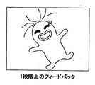
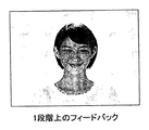
- the content image is, for example, as shown in FIG. FIG. 6 is an image diagram of an example of a content image.
- the content image of FIG. 6 represents the degree of smile at the smile level for each smile level as a face image of the user himself / herself.
- the real-time content generation unit 106 acquires a smile level from the smile level correction unit 104
- the content image for the smile level is read from the content storage unit 112.
- the real-time content presentation unit 107 displays the content image acquired from the real-time content generation unit 106 in the real-time content display field 1004 of the recording screen 1000 described later.
- the mood input unit 108 receives the current mood input from the user.
- the mood input unit 108 may use a mood icon as shown in FIG. 7 to allow the user to select the current mood by self-reporting.
- FIG. 7 is an image diagram of an example of a mood icon.
- the mood icon in FIG. 7 shows an example in which the mood is divided into six stages.
- the mood-smile level information storage unit 114 stores mood-smile level information in which a mood icon to be selected by the user is associated with a smile level.
- the mood-smile level conversion unit 109 converts the user's current mood into a smile level based on the mood icon selected by the user and the mood-smile level information.
- the end screen content generation unit 110 acquires the smile level from the mood-smile level conversion unit 109
- the end screen content generation unit 110 reads the content image of the smile level from the content storage unit 112.
- the end screen content presentation unit 111 displays the content image acquired from the end screen content generation unit 110 in the end screen content display field 1102 of the end screen 1100 described later.
- FIG. 8 is a flowchart showing an example of the overall processing of the smile feedback device according to the present embodiment.
- FIG. 9 is an image diagram of a screen displayed by the smile feedback device.
- FIG. 9 shows an example of a recording screen 1000 and an end screen 1100.
- the recording screen 1000 of FIG. 9 includes an input image display field 1002, a real-time content display field 1004, a mood selection field 1006, and a recording button 1008.
- the input image display field 1002 an image (input image) photographed by the photographing device 509 is displayed in real time.
- the real-time content display field 1004 displays the content image read from the content storage unit 112 as described above.
- the mood selection column 1006 is a selection column that displays the mood icon shown in FIG. 7 and allows the user to select the current mood.
- a record button 1008 is a button for receiving an instruction to start recording such as an input image, a smile level, and a mood from the user.
- the end screen 1100 in FIG. 9 is an example of a screen displayed after the recording of the input image, the smile level, the mood, and the like is completed.
- the end screen 1100 in FIG. 9 includes an end screen content display field 1102.
- the end screen content display field 1102 displays the content image read from the content storage unit 112 as described above.
- the smile feedback device 10 repeats the process of step S11 until the record button 1008 is pressed by the user. Therefore, the input image is displayed in real time in the input image display field 1002 of the recording screen 1000. In addition, a content image associated with the smile level (including the corrected smile level) of the user included in the input image is displayed in the real-time content display field 1004 of the recording screen 1000.
- the smile feedback device 10 proceeds to step S13 and performs end screen display processing for displaying the end screen 1100.
- FIG. 10 is a flowchart of an example of the recording screen display process.
- the input image presentation unit 101 displays an input image on the input image display field 1002 of the recording screen 1000.
- the smile value measuring unit 102 measures the smile value of the face image included in the input image.
- the smile level conversion unit 103 converts the smile value measured in step S22 into a smile level using, for example, smile level information stored in the smile level information storage unit 113, as shown in FIG.
- step S24 if the current time acquired from the clock unit 105 is a time zone for correcting the smile level (correction application time), the smile level correction unit 104 performs a process of correcting the smile level in step S25.
- the smile level is corrected so as to raise the smile level converted in step S23 by one step. If it is not the correction application time, the smile level correction unit 104 skips the process of step S25.
- step S26 the real-time content generation unit 106 reads the smile level content image corrected in step S25 from the content storage unit 112 at the correction application time. If it is not the correction application time, the real-time content generation unit 106 reads the smile-level content image converted in step S23 from the content storage unit 112.
- step S27 the real-time content presentation unit 107 displays the content image read in step S26 in the real-time content display field 1004 of the recording screen 1000.
- the smile feedback device 10 has contents associated with different smile levels depending on whether or not it is the correction application time, as shown in FIGS. 11A, 11B, 12A, and 12B.
- An image can be displayed.
- 11A and 11B are image diagrams of examples of content images using character face images.
- 12A and 12B are image diagrams of examples of content images using the face image of the user himself / herself.
- 11A and 12A are content images (ordinary feedback images) displayed when the correction application time is not reached, and are the smile-level content images converted in step S23.
- the smile feedback device 10 can display a content image having a smile level higher than the smile level of the actually measured smile value when the correction application time is reached. For example, by setting a time zone during which stress is likely to accumulate, such as at night, as the correction application time, the user will see content images with a smile level higher than his / her smile level during times when stress is likely to accumulate. The effect of stress relief by improvement of the state is expected.
- the real-time content presentation unit 107 may display an impression evaluation word corresponding to a smile value as shown in FIG.
- FIG. 13 is an explanatory diagram of an example of an impression evaluation word corresponding to a smile value. “Ruriko Takano: Effect of Makeup and Smile Level on Face Impression Evaluation, Journal of Japanese Society of Facial Sciences, No. 10 Volume, pp. 37-48” reports the effect of smile degree on facial impression evaluation. FIG. 13 associates smile values with impression evaluation words based on such reports.
- FIG. 14 is a flowchart of an example of the end screen display process.
- the mood-smile level conversion unit 109 converts the mood icon selected by the user from the mood selection field 1006 into a smile level using the mood-smile level information.
- the mood-smile level conversion unit 109 performs processing for correcting the smile level converted in step S31. In the process of correcting the smile level performed in step S32, for example, the smile level is corrected so as to raise the smile level converted in step S31 by one level.
- step S33 the end screen content generation unit 110 reads the smile level content image corrected in step S32 from the content storage unit 112.
- the end screen content presentation unit 111 displays the content image read in step S 33 in the end screen content display field 1102 of the end screen 1100.
- the smile feedback device 10 can display a smile level content image in which the smile level corresponding to the user's current mood is increased by one level in the end screen content display field 1102. That is, according to the end screen display process of FIG. 14, the smile feedback device 10 can display a content image with a smile level higher than the user's current mood. The user sees a content image with a smile level higher than the current mood, and is expected to have a stress relieving effect by improving the emotional state.
- the first embodiment converts the current mood input by the user from the mood input unit 108 to a smile level, corrects the smile level to be raised by one step, and then ends the corrected smile level content image.
- the corrected smile level content image corrected so as to raise the smile level of the face image included in the input image by one step is displayed in the end screen content display field 1102 of the end screen 1100.
- FIG. 15 is a processing block diagram of an example of a smile feedback device according to the second embodiment.
- the smile level correction unit 104 of the smile feedback device 10 of FIG. 15 performs correction of the smile level provided to the real-time content generation unit 106 as shown in the first embodiment, as well as the end screen content generation unit 110. Make a smile level correction.
- the smile level provided to the end screen content generation unit 110 may be corrected regardless of the current time provided from the clock unit 105, or the current time provided from the clock unit 105 may correct the smile level. It may be performed when it is a time zone.
- the end screen content generation unit 110 of the smile feedback device 10 in FIG. 15 acquires the smile level corrected by the smile level correction unit 104 so as to raise it by one step. Further, the end screen content generation unit 110 in FIG. 15 acquires the mood selected by the user from the mood input unit 108.
- the end screen content generation unit 110 acquires the smile level corrected so as to be raised by one step from the smile level correction unit 104, the content image for the smile level is read from the content storage unit 112.
- the end screen content presentation unit 111 displays the content image acquired from the end screen content generation unit 110 in the end screen content display field 1102 of the end screen 1100 described later.
- FIG. 16 is a flowchart of an example of the end screen display process.
- the end screen content generation unit 110 acquires the smile level corrected by the smile level correction unit 104 so as to be raised by one level.
- the end screen content generation unit 110 reads the smile level content image acquired in step S41 from the content storage unit 112.
- the end screen content presentation unit 111 displays the content image read in step S 42 in the end screen content display field 1102 of the end screen 1100.
- the smile feedback device 10 can display a content image of a smile level obtained by raising the smile level of the user's face image included in the input image by one level in the end screen content display field 1102.
- the smile feedback device 10 displays a content image having a smile level higher than the smile level of the user included in the input screen and improves the emotional state of the user, thereby realizing an effect of eliminating the user's stress.
- the smile value of the user's face image included in the input image or the current mood input by the user from the mood input unit 108 is converted into a smile level.
- the third embodiment calculates a comprehensive smile value (a mood adaptive smile value) based on the smile value of the user's face image included in the input image and the mood value representing the user's current mood, It converts mood-adaptive smile values into smile levels.
- FIG. 17 is a processing block diagram of an example of a smile feedback device according to the present embodiment.
- the smile feedback device 10 includes an image input unit 100, an input image presentation unit 101, a smile value measurement unit 102, a smile level conversion unit 103, a smile level correction unit 104, a clock unit 105, a content storage unit 112, and a smile level information storage unit 113.
- the image input unit 100 acquires an image (input image) captured by the image capturing device 509. Note that when the input image is a moving image, the image input unit 100 uses one frame at a certain time point as the input image. Thus, in this embodiment, a smile value is measured from a still image.
- the image input unit 100 provides the input image to the input image presenting unit 101 and the smile value measuring unit 102.
- the input image presentation unit 101 displays the input image acquired from the image input unit 100 in the input image display field 1002 of the recording screen 1000.
- the smile value measuring unit 102 performs smile recognition of a face image included in the input image acquired from the image input unit 100, and measures a normalized smile value from 0.0 to 1.0, for example.
- the mood input unit 108 uses, for example, the mood icon shown in FIG. 7, and allows the user to select the current mood by self-reporting.
- the mood icon of FIG. 7 the leftmost sad face is set as 0.0 and the rightmost smile is set as 1.0.
- a numerical value at an equal interval is set as the mood value of the mood icon between the leftmost mood icon and the rightmost mood icon.
- the mood adaptive smile value calculation unit 121 calculates a mood adaptive smile value obtained by adapting the mood value of the mood icon selected by the user by the mood input unit 108 to the smile value measured by the smile value measurement unit 102.
- the mood adaptive smile value calculation unit 121 calculates the mood adaptive smile value by the following equation (1), for example.
- S represents a smile value.
- M represents a mood value.
- Ws represents a weighting coefficient of the smile value.
- Wm represents a weighting coefficient of the mood value.
- Ws and Wm how much the influence of the mood value is increased is adjusted by the weighting coefficients Ws and Wm.
- the total value of the two weighting factors Ws and Wm is 1.0, and the values of the respective weighting factors Ws and Wm are 0 or more and 1 or less.
- the smile value S is 0.75
- the mood value M is 0.4
- the weighting factors Ws and Wm are the same weighting 0.5
- the expression (1) does not take the mood value M into consideration, and the smile value S becomes the mood adaptive smile value T.
- the smile value S and the mood value M are normalized to 0 or more and 1 or less, and the total value of the two weighting factors Ws and Wm is set to 1.0.
- the value T is also a normalized value from 0 to 1.
- the smile level information storage unit 113 divides the range 0 to 1 of the mood adaptive smile value T calculated by the mood adaptive smile value calculation unit 121 and associates each range of the mood adaptive smile value T with a smile level.
- FIG. Smile level information as shown is stored.
- FIG. 18 is a configuration diagram of an example of smile level information. The smile level information in FIG. 18 divides the range 0 to 1 of the mood adaptive smile value T calculated by the mood adaptive smile value calculation unit 121 into 7 and the interval obtained by dividing the range 0 to 1 by 7 of the number of smile levels ( ⁇ 0.143).
- the smile level information does not necessarily divide the range 0 to 1 of the mood adaptive smile value T calculated by the mood adaptive smile value calculation unit 121, and may divide it unevenly.
- smile level information in which a low mood adaptive smile value T is converted into a high smile level may be used for a user who is not good at smiling.
- the smile level conversion unit 103 converts the mood adaptive smile value T into a smile level based on the mood adaptive smile value calculated by the mood adaptive smile value calculation unit 121 and the smile level information of FIG.
- the clock unit 105 provides the current time.
- the smile level correction unit 104 corrects the smile level so that the smile level is higher than the smile level converted by the smile level conversion unit 103 if the current time acquired from the clock unit 105 is a time zone for correcting the smile level. To do. In this embodiment, an example will be described in which the smile level correction unit 104 corrects the smile level so as to raise the smile level by one level.
- the smile level converted by the smile level conversion unit 103 is the highest level (for example, smile level 6 in FIG. 18)
- the smile level correction unit 104 maintains the smile level converted by the smile level conversion unit 103.
- the smile level correction unit 104 does not correct the smile level unless the current time acquired from the clock unit 105 is a time zone for correcting the smile level.
- Smile level correction by the smile level correction unit 104 feeds back to the user a content image whose smile level is higher than the user's actual smile value and mood value, thereby gradually making the user's feeling positive and eliminating the user's stress. It is performed aiming at the effect.
- the smile feedback device 10 assumes that, for example, a content image of a smile level that is one step higher is used as a feedback image to the user before going to bed at the end of the day or when waking up.
- the content storage unit 112 stores content images associated with each smile level. Further, when the content generation unit 122 acquires the smile level from the smile level correction unit 104, the content generation unit 122 reads the content image of the smile level from the content storage unit 112. The content presentation unit 123 displays the content image acquired from the content generation unit 122 in the real-time content display field 1004 of the recording screen 1000.
- the smile feedback device 10 in FIG. 17 does not necessarily have to prepare a content image associated with the smile level in the content storage unit 112 in advance, and uses a technique called morphing to make one user's face image. Then, the image processing for changing the expression according to the smile level may be performed, and a content image associated with the smile level may be prepared.
- FIG. 19 is a flowchart of an example of the recording screen display process.
- the input image presentation unit 101 displays an input image in the input image display field 1002 of the recording screen 1000.
- the smile value measuring unit 102 measures the smile value of the face image included in the input image.
- step S53 the mood adaptive smile value calculation unit 121 acquires the mood value of the mood icon last selected by the user from the mood input unit 108. Note that the process of step S53 does not wait for the user to select a mood icon, but acquires the mood value of the mood icon last selected by the user. Further, it is assumed that the user can select a mood icon at an arbitrary timing from the mood selection field 1006 in FIG. 9 regardless of the recording screen display process shown in FIG.
- the default mood value may be used, or the first embodiment
- the smile value may be converted into a smile level as shown in FIG.
- step S54 the mood adaptive smile value calculating unit 121 applies a mood adaptive smile value obtained by adapting the mood value of the mood icon selected by the user with the mood input unit 108 to the smile value measured by the smile value measuring unit 102. calculate.
- step S55 the smile level conversion unit 103 converts the mood adaptive smile value calculated in step S54 into a smile level using, for example, smile level information stored in the smile level information storage unit 113. To do.
- step S56 the smile level correction unit 104 corrects the smile level by one step in step S57 if the current time acquired from the clock unit 105 is a time zone for correcting the smile level (within the correction application time). Processing is performed, and the process proceeds to step S58.
- step S58 the smile level correction unit 104 determines whether or not the corrected smile level converted in step S57 exceeds the maximum level. If the corrected smile level exceeds the maximum level, the smile level correction unit 104 proceeds to step S59, corrects the corrected smile level to the maximum level, and then proceeds to step S60. If the smile level after correction does not exceed the maximum level, the smile level correction unit 104 proceeds from step S58 to step S60.
- step S60 the content generation unit 122 reads out the content image of the smile level (below the maximum level) corrected in step S25 from the content storage unit 112 at the correction application time. If the correction application time is not reached, the content generation unit 122 reads the smile-level content image converted in step S55 from the content storage unit 112.
- step S61 the content presentation unit 123 displays the content image read in step S60 in the real-time content display field 1004 of the recording screen 1000.
- the smile feedback device 10 is associated with a different smile level depending on whether or not it is the correction application time, as shown in FIGS. 11A, 11B, 12A, and 12B.
- a content image can be displayed.
- the smile feedback device 10 displays a content image having a smile level higher than the smile level of the actually measured smile value. For example, by setting a time zone during which stress is likely to accumulate, such as at night, as a correction application time, the user can view content images with a smile level higher than his / her smile level during times when stress is likely to accumulate, thus relieving stress. Can be expected.
- the end screen display process may be performed so as to display a content image of a smile level obtained by raising the smile level associated with the user's mood by one step, as shown in the first embodiment. Further, in the end screen display process, as shown in the second embodiment, a content image of a smile level obtained by raising the smile level of the user's face image included in the input image by one step may be displayed. Further, in the end screen display process, a smile level content image obtained by raising the smile level converted from the mood adaptive smile value by the smile level conversion unit 103 by one step may be displayed.
- the process of displaying the feedback image is performed at the timing when the user inputs the mood after the smile feedback device 10 acquires the input image.
- the smile feedback device 10 of the present embodiment does not use the user's mood or can automatically obtain the mood value from the user's face image or biometric information included in the input image, a series of processing Can be repeated automatically.
- the smile feedback device 10 can continuously acquire a face image from an input image and measure a smile value in real time, thereby repeatedly performing a series of processes up to displaying the feedback image in a short time.
- a technique for measuring a mood value from a face image a technique for estimating an emotion from a face image, a technique for estimating an emotion from speech, and the like can be used.
- the smile feedback device 10 of the present embodiment may accept the current mood input from the user by hand input, or may accept the current user mood value automatically acquired from the face image or biometric information as an input.
- the smile feedback device 10 of the present embodiment may constitute a mood adaptive smile value calculation unit 121 that accepts not only smile values and mood values, but also more parameters such as fatigue levels and tension levels as inputs.
- a mood adaptive smile value calculation unit 121 that accepts not only smile values and mood values, but also more parameters such as fatigue levels and tension levels as inputs.
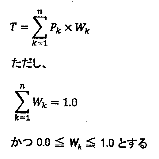
- the final parameter adaptive smile value obtained by weighting each parameter can be generalized to be expressed by Expression (2).
- an n-dimensional table may be created according to the number of types of parameters, and a parameter adaptive smile value may be set in the table.
- the smile feedback device 10 can acquire the parameter adaptive smile value by referring to the corresponding table item from the n types of parameter values actually acquired.
- the advantage of this method is that it can express the distribution of smile values, which is difficult to express with linear weighting.
- FIG. 20 is a two-dimensional table with smile values and mood values as parameters.
- the mood value is maximum (1.0)
- the feedback image may be a moving image material or audio.
- the feedback image may be a moving image that changes from a true face to a smile of a specific smile level, and at the same time, a sound such as “Tomorrow with a smile” may be reproduced.
- a feedback image may be presented by changing background music and sound effects (SE) according to the smile level.
- SE background music and sound effects
- the feedback image may simultaneously display impressive words (such as the impression evaluation word shown in FIG. 13) associated with the smile level.
- the smile feedback device 10 has the word “active smile” when the smile level is the highest, the word “is a reliable expression” when the smile level is the lowest, and the “attractive” when the smile level is intermediate
- a keyword that expresses a specific impression, such as the word “is a beautiful smile”, may be displayed on the feedback image.
- the smile feedback device 10 of the present embodiment has been described as an example in which correction is performed to raise the smile level by one step according to the time zone.
- the correction condition is not limited to the time zone, and for example, it is conceivable to correct the smile level depending on the fatigue level of the user.
- the degree of fatigue may be self-reported by the user or may be automatically input.
- the degree of fatigue can be automatically input by a method of estimating from the magnitude of the momentum in conjunction with a wearable activity meter or a method of using a degree of fatigue using an index called flicker value.
- the smile feedback device 10 has been described as an example in the above embodiment, the processing blocks shown in FIG. 4 and the like are distributed in the smile feedback server device 12 and the smile feedback client device 14 shown in FIG. 1B. It goes without saying that it is good.
- the user's emotional state is improved by presenting the user with a facial image with a smile level higher than the actual user's smile level in a cloud service or the like in which the user can record the smile level and mood.
- the mental health function can be made positive.
- Smile feedback apparatus 10
- Smile feedback server apparatus 14
- Smile feedback client apparatus 16
- Network 100
- Image input part 101
- Input image presentation part 102
- Smile value measurement part 103
- Smile level conversion part 104
- Smile level correction part 105
- Real-time content presentation unit 108
- Mood input unit 109
- Mood-smile level conversion unit 110
- End screen content generation unit 111
- End screen content presentation unit 112
- Content storage unit 113
- Smile level information storage unit 114
- Mood-smile level information storage unit 121
- Mood Adaptive smile value calculation unit 122
- Content generation unit 123
- Input device 502 and 602 Display device 503 and 603 External I F 503a, 603a Recording medium 504, 604 RAM 505, 605 ROM 506, 606 CPU 507, 607 Communication I / F 508, 608 HDD 509 Imaging device B bus
Landscapes
- Engineering & Computer Science (AREA)
- Theoretical Computer Science (AREA)
- Physics & Mathematics (AREA)
- General Physics & Mathematics (AREA)
- Health & Medical Sciences (AREA)
- General Engineering & Computer Science (AREA)
- Human Computer Interaction (AREA)
- General Health & Medical Sciences (AREA)
- Oral & Maxillofacial Surgery (AREA)
- Multimedia (AREA)
- Life Sciences & Earth Sciences (AREA)
- Psychiatry (AREA)
- Biomedical Technology (AREA)
- Databases & Information Systems (AREA)
- Data Mining & Analysis (AREA)
- Computer Vision & Pattern Recognition (AREA)
- Animal Behavior & Ethology (AREA)
- Child & Adolescent Psychology (AREA)
- Pathology (AREA)
- Developmental Disabilities (AREA)
- Heart & Thoracic Surgery (AREA)
- Medical Informatics (AREA)
- Molecular Biology (AREA)
- Surgery (AREA)
- Educational Technology (AREA)
- Public Health (AREA)
- Veterinary Medicine (AREA)
- Biophysics (AREA)
- Social Psychology (AREA)
- Dermatology (AREA)
- Neurology (AREA)
- Neurosurgery (AREA)
- Psychology (AREA)
- Hospice & Palliative Care (AREA)
- Studio Devices (AREA)
- Image Analysis (AREA)
- Information Retrieval, Db Structures And Fs Structures Therefor (AREA)
- User Interface Of Digital Computer (AREA)
- Image Processing (AREA)
Abstract
Description
[第1の実施形態]
<システム構成>
図1A及び図1Bは、本実施形態に係る情報処理システムの一例の構成図である。本実施形態に係る情報処理システムは、図1Aに示すように笑顔フィードバック装置10単体で構成してもよいし、図1Bに示すようにネットワーク16で接続された笑顔フィードバックサーバ装置12及び笑顔フィードバッククライアント装置14で構成してもよい。
《笑顔フィードバック装置、笑顔フィードバッククライアント装置》
笑顔フィードバック装置10、笑顔フィードバッククライアント装置14は例えば図2A及び図2Bに示すハードウェア構成の情報処理装置により実現される。図2A及び図2Bは本実施形態に係る情報処理装置の一例のハードウェア構成図である。
笑顔フィードバックサーバ装置12は例えば図3に示すハードウェア構成の情報処理装置により実現される。図3は本実施形態に係る情報処理装置の一例のハードウェア構成図である。なお、図2A及び図2Bと同一な部分についての説明は省略する。
ここでは図1Aに示した笑顔フィードバック装置10を例として、本実施形態の概要について説明する。本実施形態の笑顔フィードバック装置10は撮影装置509により撮影されたユーザの笑顔値を計測する。笑顔フィードバック装置10は撮影装置509により撮影されたユーザの顔画像を表示装置502に表示すると共に、その顔画像から計測したユーザの笑顔値を表示装置502に表示する。また、笑顔フィードバック装置10は計測したユーザの笑顔値を笑顔レベルに変換し、笑顔レベルに対応付けられて記憶されている顔画像を表示装置502に表示する。笑顔レベルに対応付けられて記憶されている顔画像は、その笑顔レベルにおける笑顔の度合い(強度)を表す顔画像となる。例えば最も低い笑顔レベルに対応付けられる顔画像は真顔となる。また、最も高い笑顔レベルに対応付けられる顔画像は「歯を見せ口角を最大に上げた顔」となる。
ここでは図1Aに示した笑顔フィードバック装置10を例として、本実施形態のソフトウェア構成について説明する。図4は本実施形態に係る笑顔フィードバック装置の一例の処理ブロック図である。笑顔フィードバック装置10は、画像入力部100、入力画像提示部101、笑顔値計測部102、笑顔レベル変換部103、笑顔レベル補正部104、時計部105、リアルタイム用コンテンツ生成部106、リアルタイム用コンテンツ提示部107、気分入力部108、気分−笑顔レベル変換部109、終了画面用コンテンツ生成部110、終了画面用コンテンツ提示部111、コンテンツ記憶部112、笑顔レベル情報記憶部113、気分−笑顔レベル情報記憶部114を有する構成である。
《全体処理》
本実施形態に係る笑顔フィードバック装置10は、例えば図8に示すような手順で処理を行う。図8は、本実施形態に係る笑顔フィードバック装置の全体処理の一例を示したフローチャートである。笑顔フィードバック装置10はユーザにより笑顔アプリが実行されたあと、記録画面を表示する操作を受け付けると、ステップS11に進み、例えば図9に示す記録画面1000を表示するための記録画面表示処理を行う。
図10は記録画面表示処理の一例のフローチャートである。ステップS21において入力画像提示部101は記録画面1000の入力画像表示欄1002に対して入力画像の表示を行う。ステップS22に進み、笑顔値計測部102は入力画像に含まれる顔画像の笑顔値を計測する。ステップS23に進み、笑顔レベル変換部103はステップS22で計測された笑顔値を、笑顔レベル情報記憶部113に記憶されている例えば図5に示す笑顔レベル情報を用いて、笑顔レベルに変換する。
図14は終了画面表示処理の一例のフローチャートである。ステップS31において気分−笑顔レベル変換部109はユーザが気分選択欄1006から選択した気分アイコンを気分−笑顔レベル情報を用いて笑顔レベルに変換する。ステップS32に進み、気分−笑顔レベル変換部109はステップS31で変換した笑顔レベルを補正する処理を行う。ステップS32において行う笑顔レベルを補正する処理では、例えばステップS31で変換した笑顔レベルを1段階引き上げるように笑顔レベルを補正する。
[第2の実施形態]
第1の実施形態は、ユーザが気分入力部108から入力した現在の気分を笑顔レベルに変換し、その笑顔レベルを1段階引き上げるように補正したあと、補正後の笑顔レベルのコンテンツ画像を、終了画面1100の終了画面用コンテンツ表示欄1102に表示していた。第2の実施形態は、入力画像に含まれる顔画像の笑顔レベルを1段階引き上げるように補正した補正後の笑顔レベルのコンテンツ画像を、終了画面1100の終了画面用コンテンツ表示欄1102に表示する。
[第3の実施形態]
第1及び第2の実施形態は、入力画像に含まれるユーザの顔画像の笑顔値、又は、気分入力部108からユーザが入力した現在の気分、を笑顔レベルに変換している。第3の実施形態は、入力画像に含まれるユーザの顔画像の笑顔値、及び、ユーザの現在の気分を表す気分値に基づき、総合的な笑顔値(気分適応笑顔値)を算出し、その気分適応笑顔値を笑顔レベルに変換するものである。

気分適応笑顔値T=0.8×0.75+0.2×0.4=0.68となる。
気分適応笑顔値T=0.5×0.75+0.5×0.4=0.575となる。
[他の実施形態]
本実施形態の笑顔フィードバック装置10はユーザから現在の気分の入力を手入力で受け付ける他、顔画像や生体情報から自動的に取得した現在のユーザの気分値を入力として受け付けてもよい。また、本実施形態の笑顔フィードバック装置10は笑顔値と気分値だけでなく、疲労度、緊張度など、より多くのパラメータを入力として受け付ける気分適応笑顔値計算部121を構成してもよい。例えば正規化済みのパラメータPがn種類ある場合に、それぞれのパラメータに重み付けを行った最終的なパラメータ適応笑顔値を一般化すると式(2)で表現できる。
12 笑顔フィードバックサーバ装置
14 笑顔フィードバッククライアント装置
16 ネットワーク
100 画像入力部
101 入力画像提示部
102 笑顔値計測部
103 笑顔レベル変換部
104 笑顔レベル補正部
105 時計部
106 リアルタイム用コンテンツ生成部
107 リアルタイム用コンテンツ提示部
108 気分入力部
109 気分−笑顔レベル変換部
110 終了画面用コンテンツ生成部
111 終了画面用コンテンツ提示部
112 コンテンツ記憶部
113 笑顔レベル情報記憶部
114 気分−笑顔レベル情報記憶部
121 気分適応笑顔値計算部
122 コンテンツ生成部
123 コンテンツ提示部
501、601 入力装置
502、602 表示装置
503、603 外部I/F
503a、603a 記録媒体
504、604 RAM
505、605 ROM
506、606 CPU
507、607 通信I/F
508、608 HDD
509 撮影装置
B バス
Claims (9)
- 撮像画像に含まれるユーザの笑顔値を計測する笑顔値計測手段と、
前記笑顔値計測手段により計測可能な笑顔値の範囲を複数に分け、それぞれの笑顔値の範囲を笑顔レベルと対応付ける笑顔レベル情報を記憶する笑顔レベル情報記憶手段と、
前記笑顔値計測手段により計測された笑顔値と前記笑顔レベル情報記憶手段に記憶された笑顔レベル情報とに基づき、撮像画像に含まれるユーザの笑顔値を笑顔レベルに変換する笑顔レベル変換手段と、
顔画像提示部に提示する顔画像の笑顔レベルが前記笑顔レベル変換手段により変換されたユーザの笑顔レベルよりも高くなるように補正する笑顔レベル補正手段と、
を有する情報処理装置。 - 笑顔レベルごとに顔画像を記憶する顔画像記憶手段と、
前記笑顔レベル補正手段により補正されたユーザの笑顔レベルの顔画像を前記顔画像記憶手段から読み出して前記顔画像提示部に提示させる顔画像生成手段と、
を更に有すること
を特徴とする請求項1記載の情報処理装置。 - ユーザの気分を表す気分値の範囲を複数に分け、それぞれの気分値の範囲を笑顔レベルと対応付ける気分−笑顔情報を記憶する気分−笑顔レベル情報記憶手段と、
前記気分−笑顔レベル情報記憶手段に記憶された気分−笑顔情報に基づき、撮像画像に含まれるユーザの気分値を笑顔レベルに変換する気分−笑顔レベル変換手段と、
を更に有し、
前記気分−笑顔レベル変換手段は、前記顔画像提示部に提示する顔画像の笑顔レベルがユーザの気分値の笑顔レベルよりも高くなるように、撮像画像に含まれるユーザの気分値を笑顔レベルに変換することを特徴とする請求項1又は2記載の情報処理装置。 - 前記笑顔値計測手段により計測された笑顔値にユーザの気分を表す気分値を適応させた気分適応笑顔値を計算する気分適応笑顔値計算手段、を更に有し、
前記笑顔レベル情報記憶手段は、前記笑顔値計測手段により計測可能な範囲の笑顔値にユーザの気分を表す気分値を適応させた気分適応笑顔値の範囲を複数に分け、それぞれの気分適応笑顔値の範囲を笑顔レベルと対応付ける笑顔レベル情報を記憶し、
前記笑顔レベル変換手段は、前記気分適応笑顔値計算手段により計算された気分適応笑顔値と前記笑顔レベル情報記憶手段に記憶された笑顔レベル情報とに基づき、撮像画像に含まれるユーザの気分適応笑顔値を笑顔レベルに変換すること
を特徴とする請求項1又は2記載の情報処理装置。 - 前記顔画像記憶手段は、撮像画像に含まれるユーザの顔画像を笑顔レベルごとに記憶していること
を特徴とする請求項2記載の情報処理装置。 - 前記顔画像生成手段は、前記顔画像提示部に提示させる顔画像として前記笑顔レベル変換手段により変換されたユーザの笑顔レベルよりも笑顔レベルの高い顔画像を、撮像画像に含まれるユーザの顔画像からモーフィング技法により作成すること
を特徴とする請求項2記載の情報処理装置。 - 前記笑顔レベル補正手段は、補正適用時刻内であれば、前記顔画像提示部に提示する顔画像の笑顔レベルが前記笑顔レベル変換手段により変換されたユーザの笑顔レベルよりも高くなるように補正することを特徴とする請求項1乃至6何れか一項記載の情報処理装置。
- コンピュータを、
撮像画像に含まれるユーザの笑顔値を計測する笑顔値計測手段、
前記笑顔値計測手段により計測可能な笑顔値の範囲を複数に分け、それぞれの笑顔値の範囲を笑顔レベルと対応付ける笑顔レベル情報を記憶する笑顔レベル情報記憶手段、
前記笑顔値計測手段により計測された笑顔値と前記笑顔レベル情報記憶手段に記憶された笑顔レベル情報とに基づき、撮像画像に含まれるユーザの笑顔値を笑顔レベルに変換する笑顔レベル変換手段、
顔画像提示部に提示する顔画像の笑顔レベルが前記笑顔レベル変換手段により変換されたユーザの笑顔レベルよりも高くなるように補正する笑顔レベル補正手段、
として機能させるためのプログラム。 - サーバ装置とクライアント装置とがネットワークを介して接続された情報処理システムであって、
撮像画像に含まれるユーザの笑顔値を計測する笑顔値計測手段と、
前記笑顔値計測手段により計測可能な笑顔値の範囲を複数に分け、それぞれの笑顔値の範囲を笑顔レベルと対応付ける笑顔レベル情報を記憶する笑顔レベル情報記憶手段と、
前記笑顔値計測手段により計測された笑顔値と前記笑顔レベル情報記憶手段に記憶された笑顔レベル情報とに基づき、撮像画像に含まれるユーザの笑顔値を笑顔レベルに変換する笑顔レベル変換手段と、
顔画像提示部に提示する顔画像の笑顔レベルが前記笑顔レベル変換手段により変換されたユーザの笑顔レベルよりも高くなるように補正する笑顔レベル補正手段と、
を有する情報処理システム。
Priority Applications (3)
| Application Number | Priority Date | Filing Date | Title |
|---|---|---|---|
| US16/086,803 US20190108390A1 (en) | 2016-03-31 | 2017-05-31 | Information processing apparatus, program, and information processing system |
| EP17773376.3A EP3438850A4 (en) | 2016-03-31 | 2017-05-31 | INFORMATION PROCESSING DEVICE AND INFORMATION PROCESSING SYSTEM |
| KR1020187032997A KR20200003352A (ko) | 2016-03-31 | 2017-05-31 | 정보처리 장치, 프로그램 및 정보처리 시스템 |
Applications Claiming Priority (2)
| Application Number | Priority Date | Filing Date | Title |
|---|---|---|---|
| JP2016-071232 | 2016-03-31 | ||
| JP2016071232A JP6778006B2 (ja) | 2016-03-31 | 2016-03-31 | 情報処理装置、プログラム及び情報処理システム |
Publications (1)
| Publication Number | Publication Date |
|---|---|
| WO2017168260A1 true WO2017168260A1 (ja) | 2017-10-05 |
Family
ID=59962673
Family Applications (1)
| Application Number | Title | Priority Date | Filing Date |
|---|---|---|---|
| PCT/IB2017/000653 Ceased WO2017168260A1 (ja) | 2016-03-31 | 2017-05-31 | 情報処理装置、プログラム及び情報処理システム |
Country Status (5)
| Country | Link |
|---|---|
| US (1) | US20190108390A1 (ja) |
| EP (1) | EP3438850A4 (ja) |
| JP (1) | JP6778006B2 (ja) |
| KR (1) | KR20200003352A (ja) |
| WO (1) | WO2017168260A1 (ja) |
Families Citing this family (5)
| Publication number | Priority date | Publication date | Assignee | Title |
|---|---|---|---|---|
| JP7496514B2 (ja) * | 2019-06-06 | 2024-06-07 | パナソニックIpマネジメント株式会社 | コンテンツ選択方法、コンテンツ選択装置及びコンテンツ選択プログラム |
| JP7388077B2 (ja) * | 2019-09-18 | 2023-11-29 | 大日本印刷株式会社 | 顔日記管理システム、顔日記記録装置、サーバ、顔日記管理方法、及びプログラム |
| CN111639511B (zh) * | 2019-09-26 | 2021-01-26 | 广州万燕科技文化传媒有限公司 | 舞台效果现场识别系统及方法 |
| CN115552460B (zh) * | 2020-05-22 | 2026-04-21 | 富士胶片株式会社 | 图像数据处理装置及图像数据处理系统 |
| CN114710553B (zh) * | 2020-12-30 | 2024-07-12 | 本田技研工业(中国)投资有限公司 | 信息获取方法、信息推送方法以及终端设备 |
Citations (5)
| Publication number | Priority date | Publication date | Assignee | Title |
|---|---|---|---|---|
| JP2010187109A (ja) * | 2009-02-10 | 2010-08-26 | Nikon Corp | 電子スチルカメラ |
| JP2010198110A (ja) * | 2009-02-23 | 2010-09-09 | Nikon Corp | 画像処理装置及び電子スチルカメラ |
| JP2010219740A (ja) * | 2009-03-16 | 2010-09-30 | Nikon Corp | 画像処理装置およびデジタルカメラ |
| JP2010226485A (ja) * | 2009-03-24 | 2010-10-07 | Nikon Corp | 画像加工装置およびデジタルカメラ |
| JP2013080464A (ja) * | 2011-09-21 | 2013-05-02 | Nikon Corp | 画像処理装置、撮像装置、及びプログラム |
Family Cites Families (4)
| Publication number | Priority date | Publication date | Assignee | Title |
|---|---|---|---|---|
| JP2005242567A (ja) * | 2004-02-25 | 2005-09-08 | Canon Inc | 動作評価装置及び方法 |
| KR20050101006A (ko) * | 2004-04-16 | 2005-10-20 | 삼성전자주식회사 | 멀티캐스트 멀티미디어 방송 서비스를 지원하는 이동통신시스템에서 제어 정보를 효율적으로 전송하는 방법 |
| JP4197019B2 (ja) * | 2006-08-02 | 2008-12-17 | ソニー株式会社 | 撮像装置および表情評価装置 |
| US10365716B2 (en) * | 2013-03-15 | 2019-07-30 | Interaxon Inc. | Wearable computing apparatus and method |
-
2016
- 2016-03-31 JP JP2016071232A patent/JP6778006B2/ja active Active
-
2017
- 2017-05-31 KR KR1020187032997A patent/KR20200003352A/ko not_active Withdrawn
- 2017-05-31 WO PCT/IB2017/000653 patent/WO2017168260A1/ja not_active Ceased
- 2017-05-31 EP EP17773376.3A patent/EP3438850A4/en not_active Withdrawn
- 2017-05-31 US US16/086,803 patent/US20190108390A1/en not_active Abandoned
Patent Citations (5)
| Publication number | Priority date | Publication date | Assignee | Title |
|---|---|---|---|---|
| JP2010187109A (ja) * | 2009-02-10 | 2010-08-26 | Nikon Corp | 電子スチルカメラ |
| JP2010198110A (ja) * | 2009-02-23 | 2010-09-09 | Nikon Corp | 画像処理装置及び電子スチルカメラ |
| JP2010219740A (ja) * | 2009-03-16 | 2010-09-30 | Nikon Corp | 画像処理装置およびデジタルカメラ |
| JP2010226485A (ja) * | 2009-03-24 | 2010-10-07 | Nikon Corp | 画像加工装置およびデジタルカメラ |
| JP2013080464A (ja) * | 2011-09-21 | 2013-05-02 | Nikon Corp | 画像処理装置、撮像装置、及びプログラム |
Non-Patent Citations (1)
| Title |
|---|
| See also references of EP3438850A4 * |
Also Published As
| Publication number | Publication date |
|---|---|
| KR20200003352A (ko) | 2020-01-09 |
| US20190108390A1 (en) | 2019-04-11 |
| EP3438850A4 (en) | 2019-10-02 |
| JP6778006B2 (ja) | 2020-10-28 |
| EP3438850A1 (en) | 2019-02-06 |
| JP2017182594A (ja) | 2017-10-05 |
Similar Documents
| Publication | Publication Date | Title |
|---|---|---|
| US20200275848A1 (en) | Virtual reality guided meditation with biofeedback | |
| WO2017168260A1 (ja) | 情報処理装置、プログラム及び情報処理システム | |
| JP7288064B2 (ja) | 視覚型仮想エージェント | |
| Lammert et al. | Data-driven analysis of realtime vocal tract MRI using correlated image regions | |
| Dejonckere et al. | Automated tracking of quantitative parameters from single line scanning of vocal folds: A case study of the ‘messa di voce’exercise | |
| JP6941800B2 (ja) | 感情推定装置、感情推定方法及びプログラム | |
| JP2017176580A (ja) | 感情制御装置、感情制御方法、およびプログラム | |
| JP2023109741A (ja) | 生体リズム最適化によるディープラーニング睡眠アシスタントシステム | |
| CN119864040A (zh) | 一种语音驱动数字人口型的方法 | |
| EP4339809A1 (en) | Method and apparatus for generating music file, and electronic device and storage medium | |
| JP2017164215A (ja) | 関心度推定装置、関心度推定方法、プログラムおよび記録媒体 | |
| JP6515899B2 (ja) | 音声対話装置及びその制御方法 | |
| CN110545386B (zh) | 用于拍摄图像的方法和设备 | |
| WO2018198447A1 (ja) | 情報処理装置および情報処理方法 | |
| JP7697455B2 (ja) | 情報処理装置、情報処理方法、およびプログラム | |
| JP2023160515A (ja) | 反応判定装置 | |
| JP7600614B2 (ja) | コンテンツ出力装置、コンテンツ出力方法、およびプログラム | |
| WO2022113276A1 (ja) | 情報処理装置、制御方法及び記憶媒体 | |
| Watson et al. | A PCA-Based Active Appearance Model for Characterising Modes of Spatiotemporal Variation in Dynamic Facial Behaviours | |
| CN119069070B (zh) | 一种用于口腔患者的口面肌功能训练系统与方法 | |
| 宮脇亮輔 et al. | A Data Collection Protocol, Tool, and Analysis of Multimodal Data at Different Speech Voice Levels for Avatar Facial Animation | |
| WO2024154292A1 (ja) | 内面状態推定装置、内面状態推定方法及び記憶媒体 | |
| JP2026019883A (ja) | システム | |
| KR20250009901A (ko) | 인지기능 훈련을 위한 리듬 패턴을 제공하는 방법 및 전자 장치 | |
| CN118690454A (zh) | 基于建筑要素的情感确定模型的训练方法及相关设备 |
Legal Events
| Date | Code | Title | Description |
|---|---|---|---|
| NENP | Non-entry into the national phase |
Ref country code: DE |
|
| WWE | Wipo information: entry into national phase |
Ref document number: 2017773376 Country of ref document: EP |
|
| ENP | Entry into the national phase |
Ref document number: 2017773376 Country of ref document: EP Effective date: 20181031 |
|
| ENP | Entry into the national phase |
Ref document number: 20187032997 Country of ref document: KR Kind code of ref document: A |
|
| 121 | Ep: the epo has been informed by wipo that ep was designated in this application |
Ref document number: 17773376 Country of ref document: EP Kind code of ref document: A1 |