WO2017168539A1 - Système de communication sans fil - Google Patents
Système de communication sans fil Download PDFInfo
- Publication number
- WO2017168539A1 WO2017168539A1 PCT/JP2016/060012 JP2016060012W WO2017168539A1 WO 2017168539 A1 WO2017168539 A1 WO 2017168539A1 JP 2016060012 W JP2016060012 W JP 2016060012W WO 2017168539 A1 WO2017168539 A1 WO 2017168539A1
- Authority
- WO
- WIPO (PCT)
- Prior art keywords
- time slot
- data
- master station
- station
- vehicle
- Prior art date
- Legal status (The legal status is an assumption and is not a legal conclusion. Google has not performed a legal analysis and makes no representation as to the accuracy of the status listed.)
- Ceased
Links
Images


Classifications
-
- H—ELECTRICITY
- H04—ELECTRIC COMMUNICATION TECHNIQUE
- H04W—WIRELESS COMMUNICATION NETWORKS
- H04W72/00—Local resource management
- H04W72/04—Wireless resource allocation
-
- H—ELECTRICITY
- H04—ELECTRIC COMMUNICATION TECHNIQUE
- H04W—WIRELESS COMMUNICATION NETWORKS
- H04W74/00—Wireless channel access
- H04W74/08—Non-scheduled access, e.g. ALOHA
Definitions
- the present disclosure relates to a wireless communication system, and is applicable to, for example, a wireless communication system in which a plurality of independent subsystems that complete communication between a master station and a slave station are collected.
- beacons necessary for maintaining the wireless communication system are transmitted at regular intervals.
- a beacon or the like may interfere between adjacent subsystems.
- An object of the present disclosure is to provide a wireless communication system that reduces interference between adjacent subsystems.
- the wireless communication system includes a plurality of subsystems each including a master station and a plurality of slave stations.
- the master station and the slave station perform data transmission / reception in a superframe composed of a plurality of subframes.
- Each of the plurality of subframes includes a first time slot in which the master station transmits a beacon to the slave station, and a second time in which the master station detects a carrier of another subsystem immediately before the first time slot.
- Configuration diagram of wireless communication system according to embodiment Configuration diagram of subframe and superframe according to the embodiment
- Configuration diagram of subframe according to another embodiment Illustration for explaining the shooting training system The figure which looked at the vehicle of FIG.
- FIG. 16A Diagram for explaining link-up restart when beacon and status data interfere
- FIG. 17A Enlarged view of FIG. 17A
- Enlarged view of FIG. 18A Enlarged view of FIG. 18A
- Enlarged view of FIG. 20A Enlarged view of FIG. 20A
- Diagram for explaining synchronization protection after linkup The figure for demonstrating the case where the vehicle of the same timing joins
- the figure for demonstrating the case where the vehicle of the same timing joins Configuration diagram of subframe according to modification
- Enlarged view of FIG. 24A The figure for demonstrating the link-up process by the sub-frame which concerns on an Example.
- FIG. 1 is a configuration diagram of a wireless communication system according to an embodiment.
- the wireless communication system 1 of the present embodiment includes one master station (coordinator) 10 and a plurality of slave stations (end devices) 20, and each slave station 20 and the master station 10 are wirelessly connected and communicate directly. Configured to do. That is, it is a star type configuration centering on the master station 10.
- the master station in the present embodiment is a radio station having a function of instructing the timing of radio transmission to other stations serving as slave stations by wirelessly transmitting a synchronization signal (beacon described later in this embodiment). Means.
- the wireless communication system 1 is composed of one master station (CD) 10 and n (n: an integer of 2 or more) slave stations 20.
- n an integer of 2 or more slave stations 20.
- a configuration in which the number of slave stations 20 is 1 is also possible.
- the first slave station 20 (1),..., The nth slave station 20 (n) is described as a representative, it is referred to as a slave station 20.
- the first slave station 20 (1) may be referred to as a first end device (ED1),...
- nth slave station 20 (n) may be referred to as an nth end device (EDn).
- TDMA wireless communication is performed in accordance with the standard IEEE 802.15.4. That is, time division wireless communication is performed between the master station 10 and the slave station 20 according to the superframe.
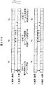
- FIG. 2 is a configuration diagram of a subframe and a superframe according to the embodiment.
- the subframe (Sub Frame) defines a period (time slot) in which the master station 10 and each slave station 20 can transmit frames.
- 3 includes a beacon transmission (TSb) 31, a first coordinator data transmission (TSc1) 32 (1),..., An m-th coordinator data transmission (TScm) 32 (m ), First end device (end device) data transmission (TS1) 33 (1),..., Nth end device data transmission (TSn) 33 (n), carrier sense (TScs) 34 time slots (Time Slot: TS).
- the number of time slots is determined by the amount of data transmitted between the master station 10 and the slave station 20 and the number of slave stations 20.
- Data transmission / reception between the master station 10 and the slave station 20 is performed by periodically repeating a super frame (Supper Frame) 300 including a plurality (k) of subframes 30.
- Carrier frequency (f1) of the first subframe (SBF1) 30 (1), carrier frequency (f2) of the second subframe (SBF2) 30 (2),..., Carrier frequency of the kth subframe (SBFk) (Fk) may be different from each other, or k may be divided into several groups so that carrier frequencies in the groups are different, thereby reducing interference with adjacent wireless communication systems.
- One frame can be transmitted in one time slot.
- the length of each time slot is determined as the time required for wireless transmission of this data based on the maximum data length of one frame.
- the length of each time slot may not be uniform.
- a guard time (not shown) is provided between a certain time slot and the next time slot. The guard time is provided to prevent interference between signals in different time slots, and transmission / reception is switched during the guard time.
- One frame includes one or a plurality of packets.
- the frame includes a header, transmission data, and a footer, and the header can accommodate the transmission source address and the transmission destination address of the frame.
- the footer includes communication error detection data.
- the beacon transmission (TSb) 31 is a time slot in which the master station (coordinator) 10 outputs a frame including a beacon (synchronization reference signal).
- Each of the master station 10 and the slave station 20 is synchronized based on the synchronization reference signal output by the beacon transmission 31 and calculates a time slot in which the local station can transmit or receive data.
- the first coordinator data transmission 32 (1),..., The m-th coordinator data transmission 32 (m) is described as a representative, it is referred to as a coordinator data transmission 32.
- one coordinator data transmission 32 for example, the first coordinator data transmission 32 (1)
- data to a plurality of slave stations 20 can be multiplexed in one frame.
- the first end device data transmission 33 (1),..., The nth end device data transmission 33 (n) are respectively transmitted from the slave stations (end devices) 20 (1) to 20 (n) to the master station 10 (coordinator). It is a time slot that can transmit data to.
- the end device data transmission 33 (1) is the slave station 20 (1), that is, the time slot TS1 in which data can be transmitted from the end device 1 to the coordinator 10
- the end device data transmission 33 (n) is the slave station 20 ( n), that is, a time slot TSn in which data can be transmitted from the end device n to the coordinator 10.
- the number of end devices n 1
- the number of end device data transmissions 33 can be 1.
- the first end device data transmission 33 (1),..., The nth end device data 33 (n) is described as a representative, it is referred to as an end device data transmission 33.
- Carrier sense (TScs) 34 is a time slot for detecting beacon transmission or data transmission of an adjacent wireless communication system. The function of the carrier sense 34 will be described below.
- FIG. 3 is a diagram illustrating a state in which different wireless communication subsystems are adjacent to each other in the wireless communication system according to the embodiment.
- FIG. 4 is a timing diagram showing a case where a beacon of an adjacent wireless communication subsystem is sensed.
- FIG. 5 is a timing chart showing a case where data of an adjacent wireless communication subsystem is sensed.
- the master station 10A, the first slave station 20A (1),..., The nth slave station 20A (n) constitutes a wireless communication subsystem (hereinafter simply referred to as “subsystem”) 1A.
- the station 10B, the first slave station 20B (1),..., The nth slave station 20B (n) constitute the subsystem 1B.
- the subsystems 1A and 1B have the same configuration as that of the wireless communication system 1 in FIG.
- the number of slave stations of the subsystem 1B may be different from that of the subsystem 1A.
- the master station 10B, the first slave station 20B (1), the seventh slave station 20B (7), and the nth slave station 20B ( n) may be in a position where radio waves from the master station 10A of the subsystem 1A can be received.
- the beacon timing of the subsystem 1A and the beacon timing of the subsystem 1B overlap for example, a beacon collision occurs at the position of the first slave station 20B (1).
- FIG. 5 if the beacon timing of the subsystem 1A and the data transmission timing of the subsystem 1B overlap, data interference occurs at the position of the first slave station 20B (1), for example.
- the parent station in the beacon transmission 31 next to the detected carrier sense 34 10A does not perform beacon transmission but performs beacon transmission with a predetermined number of subframes shifted to avoid a beacon collision with the parent station 10B or interference between the beacon transmission of the parent station 10A and the data transmission of the subsystem 1B.
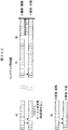
- FIG. 6 is a configuration diagram of a subframe according to another embodiment. 6 includes a beacon transmission (TSb) 31, a first coordinator data transmission (TSc1) 32 (1),..., An m-th coordinator data transmission (TScm) 32 (m), and a first end device. Data transmission (TS1) 33 (1),..., First end device data transmission (TSn) 33 (n), and carrier sense (TScs) 34 are configured to include each time slot. Beacon transmission (TSb) 31, first coordinator data transmission (TSc1) 32 (1), ...
- TScm m-th coordinator data transmission
- TS1 first end device data transmission
- TScs Carrier sense
- TSn n-th end device data transmission
- the wireless communication system according to the embodiment is not limited to the shooting training system, but can be applied to a system including a plurality of adjacent wireless communication subsystems.
- FIG. 7 is a diagram for explaining the shooting training system.
- FIG. 8 is a top view of the vehicle shown in FIG.
- the shooting training system includes a vehicle 110 including a light receiver (slave station) 111 (1) to 111 (8) and a presenter (master station) 112, and a laser transmitter 120.
- the light receivers 111 (1) to 111 (8) are described as a representative, they are referred to as the light receiver 111.
- the number of light receivers 111 is eight in the example of FIG. 8, but is not limited to eight.
- the light receiver 111 and the indicator 112 can be installed in helicopters, ships, personnel, buildings, and the like.
- a laser beam 121 emitted from the laser transmitter 120 is used as a simulated bullet without using an actual bullet.
- the laser beam 121 includes information such as an identifier (ID) of the laser transmitter 120 that has emitted the laser beam 121, a firearm type, and a bullet type as the emission information.
- ID an identifier
- the light receiver 111 attached to the vehicle 110 detects the laser beam 121 to detect the impact that the light receiver 111 has received. That is, when detecting the laser beam 121, the light receiver 111 reads the emission information included in the laser beam 121 and wirelessly transmits it to the display unit 112 together with the bullet information.
- the bulleted information is information such as a wear category indicating the degree of wear due to the bullet, and a worn part (shot position).
- the presenter 112 When receiving the bullet information from the light receiver 111, the presenter 112 displays the bulleted situation, that is, outputs the bulleted situation, using one or more of light emission, sound generation, and smoke according to the contents.
- the wireless communication method of the standard IEEE 802.15.4 is used for data transmission between the light receiver (slave station) and the presenter (master station).
- specifications of a communication method (access method, data transmission sequence, etc.) based on TDMA are established for a data link layer (MAC layer) of a wireless network.
- time slots in which the master station and the slave station can transmit frames are set in advance in one superframe.
- the master station and the slave station perform transmission in the set time slots.
- the super frame indicates a structure on the time axis that defines time slots in which the master station and the slave stations can transmit frames.
- FIG. 9 is a configuration diagram of the presenting device and the light receiving device according to the embodiment.
- the presenter (coordinator) 112 includes a wireless module 11, a display unit 15, and a battery 16.
- the wireless module 11 includes a control unit 12, a transmission / reception unit 13, and a storage unit 14.
- the transceiver 13 includes an antenna 13 a for transmitting and receiving radio waves to and from the light receiver 111.
- the battery 16 supplies power to each component of the indicator 112.
- the control unit 12 controls the operation of each component of the display unit 112 and the entire display unit 112.
- the control unit 12 transmits data such as status data, operation setting data, and ACK data based on the timing of the superframe time slot stored in the storage unit 14. Determine the timing.
- the control unit 12 causes the light receiver 111 to transmit a beacon for detecting a time slot for transmitting data and ACK data from the transmission / reception unit 13. That is, the control unit 12 notifies the light receiver 111 of the timing at which the light receiver 111 transmits data and ACK data.
- the ACK data is an acknowledgment (also referred to as a positive response) data, that is, an affirmative sent from the receiving side to the transmitting side in order to indicate that the data transmitted from the transmitting side has been normally received at the receiving side. It is a response data.
- the transmission / reception unit 13 transmits or receives data or ACK data wirelessly with the light receiver 111 according to the control from the control unit 12.
- the storage unit 14 stores the timing of the superframe time slot. Further, the storage unit 14 holds data received from the light receiver 111 and holds data to be transmitted to the light receiver 111 according to control from the control unit 12. Data to be transmitted to the light receiver 111 is input from the control unit 12, for example.
- the display unit 15 is an output unit that outputs various types of information, and displays information received from the light receiver 111.
- the display unit 15 includes a sound generation unit 151 that emits sound, a light emission unit 152 that emits light, and a smoke generation unit 153 that emits smoke, and outputs sounds such as sound generation, light emission, and smoke generation according to information received from the light receiver 111. Do. Information input to the display unit 15 is held in the storage unit 14.
- the light receiver (end device) 111 includes a wireless module 21, a light receiving unit 25, and a battery 26.
- the wireless module 21 includes a control unit 22, a transmission / reception unit 23, and a storage unit 24.
- the transmission / reception unit 23 includes an antenna 23a for transmitting / receiving radio waves to / from the display unit 112.
- the battery 26 supplies power to each component of the light receiver 111.
- the control unit 22 controls the operation of each component of the light receiver 111 and the entire light receiver 111. Further, the control unit 22 performs control so that the information input from the light receiving unit 25 is wirelessly transmitted to the indicator 112. In addition, when performing wireless transmission to the indicator 112, the control unit 22 determines the timing for transmitting data and ACK data based on the timing of the superframe time slot stored in the storage unit 24.
- the transmission / reception unit 23 transmits or receives data or ACK wirelessly with the display unit 112 according to the control from the control unit 22.
- the storage unit 24 stores the timing of the superframe time slot based on the beacon received from the display unit 112.
- the storage unit 24 holds data received from the display unit 112 and holds data to be transmitted to the display unit 112 in accordance with control from the control unit 22.
- Data to be transmitted to the indicator 112 is input from the light receiving unit 25, for example.
- the light receiving unit 25 is an input unit that receives input of various types of information. For example, the light receiving unit 25 receives a laser beam and outputs information included in the received laser beam to the control unit 22. Information input to the light receiving unit 25 is held in the storage unit 24.
- Each of the control unit 12 and the control unit 22 includes a CPU (Central Processing Unit) and a memory for storing an operation program of each control unit as a hardware configuration.
- the CPU operates according to the operation program.
- the storage unit 14 and the storage unit 24 are each composed of a semiconductor memory (flash memory, RAM (Random Access Memory), ROM (read only memory), etc.), a magnetic disk, or the like.
- a semiconductor memory flash memory, RAM (Random Access Memory), ROM (read only memory), etc.
- ROM read only memory
- magnetic disk or the like.
- the slave station 20 is a light receiver that receives a laser beam, acquires information included in the received laser beam, and wirelessly transmits the acquired information to the display device.
- the master station 10 is a display device that is directly connected to a plurality of light receivers, receives information wirelessly transmitted from the plurality of light receivers, and performs output based on the received information. .
- FIG. 10 is a configuration diagram of a subframe according to the embodiment.
- 10 includes a beacon transmission (TSb) 31, a first coordinator data transmission (TSc1) 32 (1), a second coordinator transmission (TSc2) 32 (2), and a first end.
- FIG. 11 is a diagram illustrating a subframe period at the time of link-up.
- the indicator 112 transmits a beacon to the light receiver 111 when no carrier is detected.
- the light receiver 111 receives the beacon of its own master station and completes the synchronization.
- the light receiver 111 transmits status data to the indicator 112.
- the indicator 112 receives the status data.
- the state data is represented by solid arrows.
- the indicator 112 transmits ACK data to the light receiver 111.
- the light receiver 111 receives ACK data.
- ACK data is indicated by a broken-line arrow.
- the display unit 112 transmits operation setting data to the light receiver 111.
- the light receiver 111 receives the operation setting data and transmits ACK data to the display device 112. Complete the link up.
- the operation setting data is represented by solid arrows.
- the subsystems that perform independent communication are one master station and eight slave stations, and there are about nine subsystems in the radio notification area in one subsystem.
- the number of channels is 4 to 8, and it is assumed that interference will surely occur during operation. Therefore, the operation is divided into two patterns of link-up (when connection is established) and operation (normal operation), and a method for avoiding interference in each of them will be described.
- a frequency hopping of 4 channels a super frame is composed of sub-frames of 4 types of frequencies.
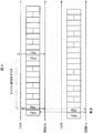
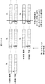
- FIG. 12 is a diagram for explaining a case where a carrier of state data of an adjacent subsystem is detected.
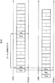
- FIG. 13 is a diagram for explaining a case where a beacon carrier of an adjacent subsystem is detected.
- the frequency of the subframe changes in the order of fA, fB, fC, fD, fA, fB, fC, fD,...,
- the frequency of the subframe changes in the order of fC, fA, fD, fB, fC, fA, fD, fB,.
- the sub-frame with the frequency of vehicle A fA and the sub-frame with the frequency of vehicle B fA partially overlap.
- the parent station of the vehicle A detects the carrier of the state data transmitted from the child station of the vehicle B to the parent station by carrier sense before the timing of beacon transmission to the child station. Therefore, the parent station of vehicle A delays the beacon transmission timing by 8 subframes to avoid interference.
- the child station of vehicle A continues to wait for a beacon on the reference channel when no beacon is received.
- the frequency of the subframe changes in the order of fA, fB, fC, fD, fA, fB, fC, fD,.
- the sub-frame with the frequency of vehicle A fA and the sub-frame with the frequency of vehicle B fA partially overlap.
- the parent station of vehicle A detects the carrier of the beacon transmitted from the parent station of vehicle B to the child station by carrier sense before the timing of beacon transmission to the child station. Therefore, the master station of the A vehicle delays the beacon transmission timing (superframe start) by 8 subframes to avoid interference.
- the child station of vehicle A continues to wait for a beacon on the reference channel when no beacon is received.
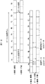
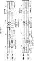
- FIG. 14A is a timing chart when interference occurs in ARQ retransmission but link-up is completed.
- FIG. 14B is an enlarged view of FIG. 14A.
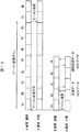
- FIG. 15A is a timing diagram when link up is completed without interference in ARQ retransmission.
- FIG. 15B is an enlarged view of FIG. 15A.
- the subframe frequency changes in the order of fA, fB, fC, fD, fA, fB, fC, fD,..., And in the B subsystem (B vehicle).
- the frequency of the subframe changes in the order of fD, fC, fB, fA, fD, fC, fB, fA,.
- the subframe with the frequency of vehicle A being fB, the subframe with the frequency of vehicle B being fB, the subframe with the frequency of vehicle A being fD, and the subframe having a frequency of vehicle B being fD partially overlap, and the broken line portion Cause interference.
- transmission of status data from the slave station of the A vehicle to the master station, transmission of ACK data from the master station of the B vehicle to the slave station, and status data transmission from the slave station to the master station are performed. have a finger in the pie.
- the first, sixth to eighth slave stations (ED1, 6 to 8) of the vehicle A perform ARQ retransmission, but the ACK data (CD1, 2) from the master station to the slave stations also interfere and cause a retry over.
- the link up is completed by receiving operational data.
- the slave stations 5 to 7 of the B vehicle perform ARQ retransmission, but ACK data (CD1, 2) from the master station to the slave station also interferes and a retry over occurs.
- link-up is completed by receiving operational data.
- the frequency of subframes changes in the order of fA, fB, fC, fD, fA, fB, fC, fD,...,
- the frequency of the subframe changes in the order of fD, fC, fB, fA, fD, fC, fB, fA,.
- the subframe with the frequency of the vehicle A of fB and the subframe of the vehicle B with the frequency fB partially overlap, and interference occurs at the broken line portion.
- transmission of status data from the slave station of the A vehicle to the master station interferes with transmission of ACK data from the master station of the B vehicle to the slave station.
- the seventh and eighth slave stations (ED7 and 8) of the A vehicle are ARQ retransmitted, and the status data is transmitted to complete the link up.
- the first to fourth slave stations of the B vehicle are ARQ retransmitted, and the status data is transmitted to complete the link up.
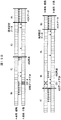
- FIG. 16A is a timing diagram in which linkup is completed by APL retransmission.
- FIG. 16B is an enlarged view of FIG. 16A.
- the frequency of subframes changes in the order of fA, fB, fC, fD, fA, fB, fC, fD,...,
- the frequency of the subframe changes in the order of fB, fD, fA, fC, fB, fD, fA, fC,.
- the subframe with the frequency of vehicle A being fB, the subframe with the frequency of vehicle B being fB, the subframe with the frequency of vehicle A being fD, and the subframe having a frequency of vehicle B being fD partially overlap, and the broken line portion Cause interference.
- transmission of status data from the slave station of the A vehicle to the master station interferes with transmission of operation setting data from the master station of the B vehicle to the slave station.
- the 4th to 7th slave stations (ED4 to 7) of the A vehicle are ARQ retransmitted, but the ACK data (CD1, 2) from the master station to the slave station also interferes and a retry over occurs.
- the link up is completed by receiving operational data.
- the operation setting data from the master station to the slave station of the B vehicle is ARQ retransmission, but the ACK data (ED4 to ED7) from the slave station to the master station also interferes and causes a retry over.
- retransmission processing by the application layer is performed.
- the retransmission timing is determined by a delay time using random numbers. This is to prevent re-interference due to retransmission at the same timing in vehicles having the same frequency hopping (FH).
- the delay time is determined by referring to the delay time table from the PAN-ID assigned with a unique number for each vehicle.
- the setting value of the delay time table is configured to be as inconsistent as possible with the FH pattern determined by the PAN-ID.
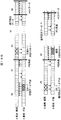
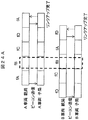
- FIG. 17A is a timing diagram when only one of the interfered subsystems completes link-up by restarting. 17B and 17C are enlarged views of FIG. 17A. 17C is connected next to FIG. 17B, and the right side part of FIG. 17B and the left side part of FIG. 17C overlap.
- FIG. 18A is a timing diagram when both interfering subsystems complete the link-up by restarting. 18B and 18C are enlarged views of FIG. 18A. 18C is connected next to FIG. 18B.
- the frequency of subframes changes in the order of fA, fB, fC, fD, fA, fB, fC, fD,...,
- the frequency of the subframe changes in the order of fC, fA, fD, fB, fC, fA, fD, fB,.
- the subframe with the frequency of vehicle A is fA and the subframe with the frequency of vehicle B are fA partially overlap, and interference occurs at the broken line portion.
- This restart process is implemented by transmitting an operation stop request from the control unit 12 to the transmission / reception unit 13 and then transmitting an operation start request after a delay time based on a random value.
- the slave station continues to wait for a beacon on the reference channel when no beacon is received.
- the subframe frequency changes in the order of fA, fB, fC, fD, fA, fB, fC, fD,..., And in the B subsystem (B vehicle).
- the subframe frequency changes in the order of fA, fB, fC, fD, fA, fB, fC, fD,.
- the sub-frames of all the frequencies of the A vehicle and the sub-frames of all the frequencies of the B vehicle overlap, and interference occurs at the broken line portion.
- the beacon transmission timings of the parent station of the A vehicle and the parent station of the B vehicle can be shifted.
- the slave station continues to wait for a beacon on the reference channel when no beacon is received.
- FIG. 19 is a diagram illustrating a positional relationship of vehicles in which a hidden terminal problem occurs during beacon transmission.
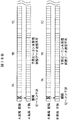
- FIG. 20A is a timing diagram for explaining the hidden terminal problem during beacon transmission.
- 20B and 20C are enlarged views of FIG. 20A. After FIG. 20B, FIG. 20C is connected.
- the carrier of the B vehicle does not reach the master station 112A of the A vehicle 110A, but the fourth vehicle station 111A (4) and the fifth slave station 111A (5) of the A vehicle 110A May arrive.
- the master station does not recognize the interference with the adjacent subsystem and the slave station interferes with the adjacent subsystem, it is called a hidden terminal problem.
- the frequency of subframes changes in the order of fA, fB, fC, fD, fA, fB, fC, fD,...,
- the frequency of the subframe changes in the order of fA, fC, fD, fB, fA, fC, fD, fB,.
- the sub-frame with the frequency of vehicle A fA and the sub-frame with the frequency of vehicle B fA overlap, and interference occurs at the broken line portion.
- beacon reception from the fourth and fifth child stations of the A vehicle interferes with transmission of a beacon from the parent station of the B vehicle to the child station.
- beacon reception from the fourth and fifth child stations of the A vehicle may interfere with transmission of operation data and the like of the B vehicle (not shown).
- the fourth child station and the fifth child station of the A vehicle cannot receive the beacon and cannot transmit the status data. Further, the 4th slave station and the 5th slave station do not receive the beacon and ARQ retransmission is not performed. Therefore, when the master station of the vehicle A detects incomplete operation data transmission even after a predetermined time (for example, 3 seconds) has passed since the beacon transmission, the master station restarts the link-up process using this as a trigger.
- a predetermined time for example, 3 seconds
- This restart process is implemented by transmitting an operation stop request from the control unit 12 to the transmission / reception unit 13 and then transmitting an operation start request after a delay time based on a random value.
- the interference generating slave station continues to wait for a beacon on the reference channel when no beacon is received.
- the slave station detects that no operational data has been received even after a predetermined time (for example, 3 seconds) has elapsed since the start of synchronization, the slave station shifts to a beacon wait on the reference channel using this as a trigger.
- FIG. 21 is a timing chart when a beacon is not transmitted by carrier sense.
- 22A and 22B are timing diagrams when vehicles having the same timing merge.
- FIG. 22B is connected after FIG. 22A.
- the master station of vehicle A when the master station of vehicle A cannot detect the carrier of another subsystem in the sense slot and transmit a beacon, it transmits the beacon with a shift of 8 subframes.
- the slave station of vehicle A receives the next beacon if synchronized. If the slave station cannot receive a beacon, it continues to transmit beacons at intervals of 8 subframes.
- the slave station shifts to beacon waiting on the reference channel as out-of-synchronization when no new beacon reception occurs in the period of 2 superframes from the previous beacon reception.
- the beacon of the A vehicle and the beacon of the B vehicle continue to collide, and the beacon not received by the slave station continues.
- slave station asynchrony occurs and the process shifts to beacon waiting.
- the master station transmits Keep-Alive data to the slave station, but there is no response if all the slave stations are asynchronous at this time.
- the wireless module is restarted when no response is received from the slave station for Keep-Alive data transmitted from the master station every 10 minutes. This is the same processing as link-up restart.
- carrier sense is performed before beacon transmission, and if detected, the specified frame is shifted to avoid collision with other subsystems. Also, by providing a link-up time and resetting (restarting) if the connection is not established within a predetermined time, the beacon transmission timing of the subsystem can be shifted by performing the link-up again. Can avoid a state in which communication cannot be performed at all due to overlapping transmission timings. Also, the hidden terminal problem can be solved.
- FIG. 23 is a configuration diagram of a subframe according to a modification.
- the subframe 30A shown in FIG. 23 corresponds to FIG. 6, and includes a beacon transmission (TSb) 31, a first coordinator data transmission (TSc1) 32 (1), a second coordinator transmission (TSc2) 32 (2), 1 end device data transmission (TS1) 33 (1),..., Eighth end device data transmission (TS8) 33 (8), and carrier sense (TScs) 34.
- FIG. 24A is a timing diagram of link-up processing using subframes according to a modification.
- FIG. 24B is an enlarged view of FIG. 24A.
- FIG. 25A is a timing diagram of link-up processing using subframes according to the embodiment.
- FIG. 25B is an enlarged view of FIG. 25A.
- the frequency of subframes changes in the order of fA, fB, fC, fD, fA, fB, fC, fD,...,
- the frequency of the subframe changes in the order of fD, fC, fB, fA, fD, fC, fB, fA,.
- the subframe with the frequency of the vehicle A of fB and the subframe of the vehicle B with the frequency fB partially overlap, and interference occurs at the broken line portion.
- transmission data including a beacon
- TScs carrier sense
- the frequency of subframes changes in the order of fA, fB, fC, fD, fA, fB, fC, fD,.
- the frequency of the subframe changes in the order of fD, fC, fB, fA, fD, fC, fB, fA,.
- the subframe with the frequency of vehicle A being fB, the subframe with the frequency of vehicle B being fB, the subframe with the frequency of vehicle A being fD, and the subframe having a frequency of vehicle B being fD partially overlap, and the broken line portion Cause interference.
- transmission of status data from the slave station of the A vehicle to the master station, transmission of ACK data from the master station of the B vehicle to the slave station, and status data transmission from the slave station to the master station are performed. have a finger in the pie.
- the first, sixth to eighth slave stations (ED1, 6 to 8) of the A vehicle are ARQ retransmitted, but ACK data (CD1, 2) from the master station to the slave stations also interfere and retry over. However, the link up is completed when the operation setting data is received.
- the fifth to seventh slave stations of vehicle B perform ARQ retransmission, but ACK data (CD1, 2) from the master station to the slave stations also interfere and retry over. However, the link up is completed when the operation setting data is received.
- ARQ retransmission can be avoided, but in the embodiment, AR retransmission and ARQ retry over occur.
- vehicle B the link-up is completed one subframe earlier in the modified example than in the example.
- the super frame is shorter than the modified example, the real-time property at the time of continuous shooting is superior to the modified example.
- the power saving is superior to the modified example.
- the slave station performs carrier sense, and if a carrier is detected at the time of transmission of the slave station, the real-time property is slightly delayed by waiting until the next beacon transmission timing. Since the collision is eliminated, the lost data is reduced, and as a result, the data arrival rate can be increased.
Landscapes
- Engineering & Computer Science (AREA)
- Computer Networks & Wireless Communication (AREA)
- Signal Processing (AREA)
- Mobile Radio Communication Systems (AREA)
Abstract
La présente invention concerne une communication sans fil qui comporte une pluralité de sous-systèmes configurés à partir d'une station maître et d'une pluralité de stations esclave. Dans chacun de la pluralité de sous-systèmes, la station maître et les stations esclave transmettent/reçoivent des données à l'aide d'une super trame configurée à partir d'une pluralité de sous-trames. Chacune de la pluralité de sous-trames comporte un premier créneau temporel dans lequel la station maître transmet une balise aux stations asservies, un deuxième créneau temporel dans lequel la station maître détecte des porteuses d'autres sous-systèmes immédiatement avant le premier créneau temporel, un troisième créneau temporel dans lequel la station maître transmet des données aux stations asservies, et un quatrième créneau temporel dans lequel les stations asservies transmettent des données à la station maître.
Priority Applications (2)
| Application Number | Priority Date | Filing Date | Title |
|---|---|---|---|
| JP2018507861A JP6630816B2 (ja) | 2016-03-29 | 2016-03-29 | 無線通信システム |
| PCT/JP2016/060012 WO2017168539A1 (fr) | 2016-03-29 | 2016-03-29 | Système de communication sans fil |
Applications Claiming Priority (1)
| Application Number | Priority Date | Filing Date | Title |
|---|---|---|---|
| PCT/JP2016/060012 WO2017168539A1 (fr) | 2016-03-29 | 2016-03-29 | Système de communication sans fil |
Publications (1)
| Publication Number | Publication Date |
|---|---|
| WO2017168539A1 true WO2017168539A1 (fr) | 2017-10-05 |
Family
ID=59963694
Family Applications (1)
| Application Number | Title | Priority Date | Filing Date |
|---|---|---|---|
| PCT/JP2016/060012 Ceased WO2017168539A1 (fr) | 2016-03-29 | 2016-03-29 | Système de communication sans fil |
Country Status (2)
| Country | Link |
|---|---|
| JP (1) | JP6630816B2 (fr) |
| WO (1) | WO2017168539A1 (fr) |
Citations (3)
| Publication number | Priority date | Publication date | Assignee | Title |
|---|---|---|---|---|
| JPH08102977A (ja) * | 1994-09-23 | 1996-04-16 | Motorola Inc | 同期通信環境を提供するための方法および装置 |
| JPH10313483A (ja) * | 1997-05-13 | 1998-11-24 | Mitsubishi Electric Corp | 無線基地局 |
| WO2009116682A1 (fr) * | 2008-03-18 | 2009-09-24 | Mitsubishi Electric Corporation | Procédé de communication dans un réseau sans fil comportant une pluralité de noeuds |
-
2016
- 2016-03-29 WO PCT/JP2016/060012 patent/WO2017168539A1/fr not_active Ceased
- 2016-03-29 JP JP2018507861A patent/JP6630816B2/ja active Active
Patent Citations (3)
| Publication number | Priority date | Publication date | Assignee | Title |
|---|---|---|---|---|
| JPH08102977A (ja) * | 1994-09-23 | 1996-04-16 | Motorola Inc | 同期通信環境を提供するための方法および装置 |
| JPH10313483A (ja) * | 1997-05-13 | 1998-11-24 | Mitsubishi Electric Corp | 無線基地局 |
| WO2009116682A1 (fr) * | 2008-03-18 | 2009-09-24 | Mitsubishi Electric Corporation | Procédé de communication dans un réseau sans fil comportant une pluralité de noeuds |
Also Published As
| Publication number | Publication date |
|---|---|
| JP6630816B2 (ja) | 2020-01-15 |
| JPWO2017168539A1 (ja) | 2019-01-10 |
Similar Documents
| Publication | Publication Date | Title |
|---|---|---|
| US6763241B2 (en) | Data communications synchronization using GPS receiver | |
| US7620409B2 (en) | Wireless communication system with channel hopping and redundant connectivity | |
| JP2009229393A (ja) | 無線測位システム及び無線測位方法 | |
| CN101753202A (zh) | 上行同步方法及终端 | |
| US12004100B2 (en) | Synchronization method and apparatus, network element, and computer storage medium | |
| US10609535B2 (en) | Blue-tooth communication system and broadcasting method thereof | |
| CN101626303B (zh) | 一种数据的发送方法、系统和设备 | |
| US11284453B2 (en) | Slave device with fast Bluetooth connection and responding method thereof | |
| CN106034121A (zh) | 一种选择性重传、握手和时隙的水下介质访问控制协议 | |
| US10056931B2 (en) | Digital remote antennas operation | |
| US8155107B2 (en) | Current position transmission in a shared robust scheme | |
| KR100769673B1 (ko) | 위치인식방법 및 위치인식시스템 | |
| JP6074852B2 (ja) | 無線通信システム | |
| JP6630816B2 (ja) | 無線通信システム | |
| EP3900469B1 (fr) | Planification bidirectionnelle dans des réseaux étendus à faible puissance | |
| JP2016032143A (ja) | 通信端末およびデータ収集システム | |
| JP2017011350A (ja) | 無線中継システム、無線中継方法および無線中継装置 | |
| CN105099513A (zh) | 蓝牙通信系统及其广播方法 | |
| US20250287372A1 (en) | Ntn scheduling delay enhancement | |
| JP5016264B2 (ja) | ワイヤレス火災報知システム | |
| JP4501787B2 (ja) | 火災報知システム | |
| JP2024514220A5 (fr) | ||
| JP5153428B2 (ja) | 通信制御方法 | |
| CN115499081B (zh) | 一种多中继跳频链路的实现方法 | |
| EP3609133B1 (fr) | Acquisition de liaisons dans des systèmes sans fil directionnels |
Legal Events
| Date | Code | Title | Description |
|---|---|---|---|
| WWE | Wipo information: entry into national phase |
Ref document number: 2018507861 Country of ref document: JP |
|
| NENP | Non-entry into the national phase |
Ref country code: DE |
|
| 121 | Ep: the epo has been informed by wipo that ep was designated in this application |
Ref document number: 16896759 Country of ref document: EP Kind code of ref document: A1 |
|
| 122 | Ep: pct application non-entry in european phase |
Ref document number: 16896759 Country of ref document: EP Kind code of ref document: A1 |