WO2017168570A1 - 空調機 - Google Patents
空調機 Download PDFInfo
- Publication number
- WO2017168570A1 WO2017168570A1 PCT/JP2016/060152 JP2016060152W WO2017168570A1 WO 2017168570 A1 WO2017168570 A1 WO 2017168570A1 JP 2016060152 W JP2016060152 W JP 2016060152W WO 2017168570 A1 WO2017168570 A1 WO 2017168570A1
- Authority
- WO
- WIPO (PCT)
- Prior art keywords
- detection sensor
- fibers
- filter
- air conditioner
- fiber
- Prior art date
- Legal status (The legal status is an assumption and is not a legal conclusion. Google has not performed a legal analysis and makes no representation as to the accuracy of the status listed.)
- Ceased
Links
Images


Classifications
-
- F—MECHANICAL ENGINEERING; LIGHTING; HEATING; WEAPONS; BLASTING
- F24—HEATING; RANGES; VENTILATING
- F24F—AIR-CONDITIONING; AIR-HUMIDIFICATION; VENTILATION; USE OF AIR CURRENTS FOR SCREENING
- F24F1/00—Room units for air-conditioning, e.g. separate or self-contained units or units receiving primary air from a central station
- F24F1/02—Self-contained room units for air-conditioning, i.e. with all apparatus for treatment installed in a common casing
- F24F1/032—Self-contained room units for air-conditioning, i.e. with all apparatus for treatment installed in a common casing characterised by heat exchangers
- F24F1/0323—Self-contained room units for air-conditioning, i.e. with all apparatus for treatment installed in a common casing characterised by heat exchangers by the mounting or arrangement of the heat exchangers
-
- F—MECHANICAL ENGINEERING; LIGHTING; HEATING; WEAPONS; BLASTING
- F24—HEATING; RANGES; VENTILATING
- F24F—AIR-CONDITIONING; AIR-HUMIDIFICATION; VENTILATION; USE OF AIR CURRENTS FOR SCREENING
- F24F1/00—Room units for air-conditioning, e.g. separate or self-contained units or units receiving primary air from a central station
- F24F1/02—Self-contained room units for air-conditioning, i.e. with all apparatus for treatment installed in a common casing
- F24F1/0328—Self-contained room units for air-conditioning, i.e. with all apparatus for treatment installed in a common casing with means for purifying supplied air
- F24F1/035—Self-contained room units for air-conditioning, i.e. with all apparatus for treatment installed in a common casing with means for purifying supplied air characterised by the mounting or arrangement of filters
-
- F—MECHANICAL ENGINEERING; LIGHTING; HEATING; WEAPONS; BLASTING
- F24—HEATING; RANGES; VENTILATING
- F24F—AIR-CONDITIONING; AIR-HUMIDIFICATION; VENTILATION; USE OF AIR CURRENTS FOR SCREENING
- F24F11/00—Control or safety arrangements
- F24F11/89—Arrangement or mounting of control or safety devices
-
- G—PHYSICS
- G01—MEASURING; TESTING
- G01N—INVESTIGATING OR ANALYSING MATERIALS BY DETERMINING THEIR CHEMICAL OR PHYSICAL PROPERTIES
- G01N27/00—Investigating or analysing materials by the use of electric, electrochemical, or magnetic means
- G01N27/02—Investigating or analysing materials by the use of electric, electrochemical, or magnetic means by investigating impedance
- G01N27/04—Investigating or analysing materials by the use of electric, electrochemical, or magnetic means by investigating impedance by investigating resistance
-
- F—MECHANICAL ENGINEERING; LIGHTING; HEATING; WEAPONS; BLASTING
- F24—HEATING; RANGES; VENTILATING
- F24F—AIR-CONDITIONING; AIR-HUMIDIFICATION; VENTILATION; USE OF AIR CURRENTS FOR SCREENING
- F24F1/00—Room units for air-conditioning, e.g. separate or self-contained units or units receiving primary air from a central station
- F24F1/02—Self-contained room units for air-conditioning, i.e. with all apparatus for treatment installed in a common casing
- F24F1/03—Self-contained room units for air-conditioning, i.e. with all apparatus for treatment installed in a common casing characterised by mounting arrangements
- F24F1/0317—Self-contained room units for air-conditioning, i.e. with all apparatus for treatment installed in a common casing characterised by mounting arrangements suspended from the ceiling
Definitions
- the present invention relates to an air conditioner having a function of detecting air contamination.
- Some indoor units for air conditioning are provided with a filter that collects dust in indoor air and a dust detection sensor that detects dust sucked from the room.
- a filter for collecting dust a filter in which fibers are knitted in a mesh shape is often used, but a filter for collecting dust by charging may be used.
- An example of a dust collection filter that charges and collects dust is disclosed in Patent Document 1.
- An example of a dust detection sensor is disclosed in Patent Document 2.
- the optical dust sensor disclosed in Patent Document 2 counts the number of dust passing through the detection region by irradiating the detection region with light and detecting reflected light from the dust passing through the detection region. If the number exceeds a certain amount, it is determined that contamination has occurred.
- substances that cause dirt in the indoor air are not limited to dust but may be chemical substances.
- sensors using MEMS Micro-Electro-Mechanical Systems
- gases such as carbon monoxide and hydrogen.
- a sensor using the MEMS technology is referred to as a “MEMS sensor”.
- the MEMS sensor has a structure in which a metal oxide is formed on a silicon substrate.
- the MEMS sensor detects a change in gas concentration as a change in voltage output on the surface of the metal oxide, and determines that contamination has occurred when a certain amount of change is detected.
- Patent Document 3 An example of a MEMS sensor is disclosed in Patent Document 3.
- the optical dust sensor disclosed in Patent Document 2 determines the degree of contamination of the filter from the amount of dust particles passing through the detection region, but it is important where the optical dust sensor is installed. For example, if there is a bias in the wind speed due to the suction of air that is sucked into the air conditioning indoor unit from the room, dust will accumulate quickly only on a part of the filter. Unless an optical dust sensor is installed at a position where dust is likely to accumulate, detection of the occurrence of dirt on the filter will be delayed. This problem also applies to the MEMS sensor disclosed in Patent Document 3. In the sensors disclosed in Patent Documents 2 and 3, there is a problem that it is difficult to determine the sensor installation position.
- the optical dust sensor disclosed in Patent Document 2 has low detection sensitivity of dust with low reflected light intensity
- the MEMS sensor disclosed in Patent Document 3 has a detection target determined by the metal type of metal oxide. Therefore, there is a problem that the detection sensitivity is bad for gases other than the detection target.
- the present invention has been made to solve the above-described problems, and provides an air conditioner that can detect dirt generated in a dust collecting portion with high sensitivity even if the air velocity distribution of air suction is uneven. There is.
- the air conditioner according to the present invention is arranged across a fan that sucks in indoor air, a dust collecting unit that collects dust in the air sucked by the fan, and an air inlet or outlet in the dust collecting unit, A dirt detection sensor provided with a fiber containing carbon nanotubes, and whether or not dirt is generated in the dust collecting unit based on a change in current flowing through the fiber when a predetermined voltage is applied to the dirt detection sensor. And a control unit.
- the sensor including carbon nanotubes having high dust detection sensitivity is provided so as to straddle the air inlet or outlet of the dust collecting portion, the dust can be collected even if the air velocity distribution of the air suction is uneven. It is possible to detect dirt generated in the collecting unit with high sensitivity.
- FIG. 4 is a side perspective view illustrating an example of the internal structure of the air conditioning indoor unit illustrated in FIG. 3.
- FIG. 2 is a side perspective view illustrating an example of an internal structure when the air conditioning indoor unit illustrated in FIG. 1 includes two heat exchangers.
- FIG. 1 It is a functional block diagram which shows one structural example of the air conditioner of Embodiment 1 of this invention. It is a figure which shows the example of 1 structure of the dirt detection sensor provided in the air conditioner of Embodiment 1 of this invention. It is a schematic diagram for demonstrating the method to detect the dirt of a filter using the dirt detection sensor shown in FIG. It is a top view which shows the structure of the modification 1 of the dirt detection sensor shown in FIG. It is a top view which shows the structure of the modification 2 of the dirt detection sensor shown in FIG. It is a top view which shows the structure of the modification 3 of the dirt detection sensor shown in FIG. It is a top view which shows the structure of the modification 4 of the dirt detection sensor shown in FIG. It is a functional block diagram which shows one structural example of the air conditioner of Embodiment 2 of this invention. It is a schematic diagram for demonstrating the method to detect the dirt of a filter using the dirt detection sensor shown in FIG.
- Embodiment 1 FIG.
- an air conditioner indoor unit called a packaged air conditioner among various indoor units.
- a packaged air conditioner is an air conditioner that allows a user to select the number and type of indoor units according to the use and volume of a room to be air-conditioned in an office or a store. Examples of the indoor unit include a floor type, a ceiling cassette type, and a ceiling type.
- the indoor unit include a floor type, a ceiling cassette type, and a ceiling type.
- the type of indoor unit is a floor-standing type will be described.
- a case where there is one indoor unit will be described, but a plurality of indoor units may be provided.
- FIG. 1 is a front view showing an example of the appearance of the air conditioning indoor unit according to Embodiment 1 of the present invention.
- a part of FIG. 1 is a perspective view, and a perspective configuration is indicated by a broken line.
- the external shape of the indoor unit shown in FIG. 1 is a box-shaped rectangular parallelepiped.
- FIG. 1 shows a state where the indoor unit is installed on the floor. In the indoor unit shown in FIG. 1, a direction perpendicular to the floor is defined as “vertical direction”, and a direction parallel to the floor is defined as “lateral direction”. As shown in FIG.
- the front side of the indoor unit is covered with a decorative panel 1 on the upper side and covered with a front side suction inlet panel 3 on the lower side.
- An opening 1a is provided in a part of the decorative panel 1, and the operation panel 2 is arranged in the opening 1a.
- the operation panel 2 includes a display unit (not shown) that displays an operation state including settings of the air conditioner and an environmental state including an indoor temperature, and an operation unit (not illustrated) for the user to instruct the setting and operation of the air conditioner. As shown).
- a touch panel may be provided on the display unit of the operation panel 2, and a part of the function of the operation unit may be executed by the touch panel.
- the front side suction port panel 3 is provided with a plurality of intake holes 4.
- a plurality of intake holes 4 In the example shown in FIG. 1, four rows of 13 intake holes 4 arranged at equal intervals in the vertical direction are provided at equal intervals in the horizontal direction.
- An opening including the plurality of intake holes 4 (13 ⁇ 4 intake holes 4) is referred to as a front side intake port 20.
- the types of intake holes 4 are grill holes, punch holes, slits, and the like.
- the intake hole 4 shown in FIG. 1 is a kind of slit.
- the material of the front side suction inlet panel 3 is, for example, iron, stainless steel, aluminum, and plastic.
- a fan case flange 5 having a blow-out port for sending the air after heat conversion into the room.
- the indoor unit is not the front side suction specification that sucks air from the front side but the rear side suction specification that sucks air from the back side will be described later.
- FIG. 2 is a rear view showing an example of the appearance of the air conditioning indoor unit shown in FIG. 1.
- a part of FIG. 2 is a perspective view, and the configuration seen through is indicated by a broken line.
- the back surface of the indoor unit is covered with a back panel 6.
- the back side panel 6 is provided with a back side suction port 7 on the side close to the floor surface.
- the back side suction port 7 is provided with a lattice (not shown) in order to prevent a thing larger than dust, such as a plastic bag, from being sucked.
- the material of the lattice is not limited to a metal such as iron and aluminum, but may be a non-metal such as plastic.
- the width which is the length in the lateral direction of the back side suction port 7 is defined as W1.
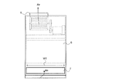
- FIG. 3 is a front view showing an example of an internal structure when the indoor unit for air conditioning shown in FIG. 1 has one heat exchanger.
- FIG. 4 is a side perspective view showing an example of the internal structure of the air conditioning indoor unit shown in FIG. 3. 3 and 4 show a configuration when the indoor unit has one heat exchanger. 3 shows a state in which the decorative panel 1 and the front-side suction inlet panel 3 shown in FIG. 1 and the filter 22 shown in FIG. 4 are removed from the indoor unit shown in FIG.
- a drain pan 15 for receiving water condensed in the heat exchanger 10 is provided below the heat exchanger 10.
- a fan 8 that sucks indoor air into the indoor unit and a motor 9 that rotationally drives the fan 8 are provided above the heat exchanger 10.
- the heat exchanger 10 is configured by integrating a pipe (not shown) through which a refrigerant circulates between the heat exchanger 10 and an outdoor unit (not shown) and a plurality of fins (not shown). 3 and 4, the external appearance of the entire heat exchanger 10 is shown in a simplified form as a plate-shaped rectangular parallelepiped. As shown in FIG. 4, the heat exchanger 10 is inclined toward the floor surface with respect to the longitudinal direction. When attention is paid to the upper and lower sides of the heat exchanger 10 shown in FIG. 4, the upper side approaches the front panel of the indoor unit, and the lower side approaches the rear panel of the indoor unit. In the configuration example shown in FIG. 4, a filter 22 is attached to the heat exchanger 10. The filter 22 is an example of a dust collecting unit that serves to collect dust in the air.
- the drain pan 15 is connected to a pipe (not shown) for discharging water accumulated in the drain pan 15.
- a motor-side pulley 12 is attached to the tip of the rotating shaft of the motor 9.
- a fan-side pulley 11 is attached to the tip of the rotating shaft of the fan 8. Belts are put on the motor-side pulley 12 and the fan-side pulley 11.
- a plurality of fins are attached to the rotating shaft of the fan 8. When the rotation shaft of the motor 9 rotates, the rotational driving force is transmitted to the fan-side pulley 11 via the motor-side pulley 12 and the belt. When the fan-side pulley 11 rotates, the plurality of fins attached to the rotation shaft of the fan 8 rotate. Thereby, indoor air is suck
- the vertical dimension of the front side suction port 20 is L1, and the vertical dimension of the back side suction port 7 is H1.
- the longitudinal dimension L1 of the front side suction port 20 is set to 300 to 1500 [mm]
- the rear side suction port. 7 has a width W1 of 500 to 2500 [mm]
- a vertical dimension H1 of the back side suction port 7 is 50 to 500 [mm].
- the back side suction port 7 is provided so that the lower end of the back side suction port 7 is located in the range of 5 to 200 mm from the upper edge of the drain pan 15 to the upper side.
- the dimensions are set so as to ensure the air volume and determine the wind speed distribution.
- the filter 22 is attached to the heat exchanger 10, but a filter may also be provided on the back side suction port 7.
- FIG. 5 is a side perspective view showing an example of the internal structure when the indoor unit for air conditioning shown in FIG. 1 has two heat exchangers.
- the indoor unit has two heat exchangers 16a and 16b.
- the heat exchanger 16a and the heat exchanger 16b are arranged in a V shape, an L shape, or a ⁇ shape as viewed from the side of the indoor unit.
- FIG. 5 is a side perspective view showing an example of the internal structure when the indoor unit for air conditioning shown in FIG. 1 has two heat exchangers.
- the indoor unit has two heat exchangers 16a and 16b.
- the front side suction port 21 is provided in the front side panel 3a, and the back side suction port 17 is provided in the back side panel 6a.
- the front-side suction port 21 has a plurality of intake holes 4 in the same manner as the front-side suction port 20 shown in FIG.
- the back side suction port 17 is provided at a position higher than the back side suction port 7 shown in FIG. Further, assuming that the vertical dimension of the back side suction port 17 is H2, the relationship is H2> H1.
- a filter 25 a is provided on the indoor unit side of the front side suction port 21, and a filter 25 b is provided on the indoor unit side of the back side suction port 17.
- the filters 25a and 25b are an example of a dust collecting unit. In the configuration example shown in FIG. 5, the heat exchangers 16a and 16b are not provided with a filter.
- the width of the back side suction port 17 is set to 500 to 2500 [mm] which is the same as the width W1 of the back side suction port 7.
- the vertical dimension H2 of the back side suction port 17 is set to 30 to 1000 [mm].
- the back side suction port 17 has a lower end of the back side suction port 17 30 on the upper side from the upper edge of the drain pan 15. It is provided so as to be in the range of up to 1000 [mm]. As described above, when both the front side and the rear side suction ports are used, the pressure loss of the suction air is reduced, the air volume is ensured, and the optimum air speed distribution is determined. The position is set.
- the longitudinal dimension L2 of the front side suction port 21 is set to 300 to 1500 [mm].
- the front air pressure is reduced by reducing the pressure loss of the intake air and determining the optimum wind speed distribution.
- the vertical dimension of the side suction port 21 is set.
- FIG. 6 is a plan view illustrating a configuration example of the filter illustrated in FIG. 4.
- the filter 22 has a frame 22a and an opening 22b.
- the opening 22b is provided in a mesh shape so that a plurality of fibers intersect. Dust sucked together with air from the room is caught by the fibers provided in a mesh shape in the opening 22b.
- FIG. 6 shows the front side suction port 20 side of the filter 22, and the opening 22 b shown in FIG. 6 corresponds to the air suction port of the filter 22.
- the back side (not shown) of the opening 22 b corresponds to the air outlet of the filter 22.
- the opening 22b is shown in the drawing, and the frame 22a is not shown in the drawing.
- the dimension of the filter 22 it is desirable that each length in the vertical direction, the horizontal direction, and the depth is 50 mm or more. Also for the other filters including the filters 25a and 25b, it is desirable that each dimension in the vertical direction, the horizontal direction, and the depth is 50 mm or more.
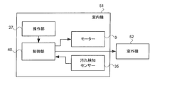
- FIG. 7 is a functional block diagram showing a configuration example of the air conditioner according to Embodiment 1 of the present invention.
- the air conditioner of Embodiment 1 has an indoor unit 51 and an outdoor unit 52.
- the indoor unit 51 includes a motor 9, a dirt detection sensor 35, an operation unit 27, and a control unit 40.
- the control unit 40 is connected to each of the motor 9, the dirt detection sensor 35, the operation unit 27, and the outdoor unit 52.
- the heat exchanger 10 is connected to the outdoor unit 52 by piping (not shown).
- the operation unit 27 is included in the operation panel 2. It is assumed that the dirt detection sensor 35 is attached to the suction port of the filter 22 shown in FIG.
- the control unit 40 includes a microcomputer (not shown) that executes processing according to a predetermined procedure, and a non-volatile memory (not shown) that stores a predetermined voltage and threshold and a reference current value to be measured. Have.
- the voltage, the reference current value, and the threshold value stored in the nonvolatile memory are values used in the stain detection determination process described later.
- the control unit 40 controls the motor 9 and the outdoor unit 52 in accordance with instructions input via the operation unit 27.
- the control unit 40 applies a predetermined voltage to the dirt detection sensor 35 at a constant cycle, measures the current flowing through the dirt detection sensor 35, and determines whether the filter 22 is dirty based on the change in the measured current. Determine whether.
- the fixed cycle is, for example, 1 to 2 [times / day].
- the voltage applied to the dirt detection sensor 35 is generated by a step-down circuit (not shown) after an AC voltage supplied from the outside is converted into a DC voltage by a voltage conversion circuit (not shown).
- the control part 40 may be provided with the function as a remote controller which also performs the air-conditioning control of another indoor unit, when the indoor unit shown in FIG. 1 is provided with two or more.
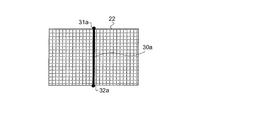
- FIG. 8 is a diagram illustrating a configuration example of a dirt detection sensor provided in the air conditioner according to Embodiment 1 of the present invention.
- the dirt detection sensor 35 shown in FIG. 7 is attached to the opening on the suction port side of the filter 22 shown in FIG. 4
- it may be attached to the opening on the outlet side.
- the filter to which the dirt detection sensor 35 is attached is not limited to the filter 22.
- the dirt detection sensor 35 may be attached to the filter 25a and the filter 25b.
- the dirt detection sensor 35 has a configuration including fibers 30 including carbon nanotubes.
- Electrodes 31 and 32 are provided at both ends of the fiber 30.
- the material of the electrodes 31 and 32 is, for example, copper.
- the fibers 30 are arranged in the filter 22 along straight lines connecting the centers of two sides facing each other in the lateral direction among the four sides of the rectangular opening.
- the opening of the filter 22 has two sets of two sides facing each other, but the fiber 30 shown in FIG. 8 connects the center points of the two sides facing each other in the lateral direction.
- the dirt detection sensor 35 shown in FIG. 8 is provided so that the fibers 30 straddle the opening of the filter 22 in the lateral direction. When the deviation of the wind speed distribution occurs in the lateral direction of the opening of the filter 22, the configuration of the dirt detection sensor 35 shown in FIG. 8 is effective.
- the material of the fiber 30 is a fiber containing 50 to 100% of carbon nanotubes.
- the fiber 30 is not a “100% carbon nanotube fiber”, for example, a carbon fiber added with a carbon nanotube can be considered.
- carbon fibers containing carbon nanotubes are referred to as “nanotube-containing carbon fibers”.
- the fiber 30 may be composed of a single fiber, or may be a structure in which a plurality of fibers are combined together like a rope to form a single bundle.
- a plurality of generated carbon nanotubes are attracted to each other by van der Waals force in a manufacturing process, and tend to have a structure called a bundle.
- This bundle may be the fiber 30.
- the fiber 30 includes carbon nanotubes, the mechanical strength is high.
- the mechanical strength increases, and it is possible to prevent a decrease in the sensitivity of the sensor due to deflection due to the air suction force. Deflection of the filter due to air blown from the room, dust, or the like has little influence on the dirt detection sensor 35.
- the elongation rate of the fiber 30 due to deflection or the like is about 0.1 to 2%, but the influence on the sensitivity of the dirt detection is less than that.
- the thickness of the fiber 30 can be in the range of 1 ⁇ m to 10 mm.
- the case where the thickness is 1 ⁇ m is, for example, the case of one carbon nanotube.
- the case where the thickness is 10 mm is, for example, the case of the bundle or the nanotube-containing carbon fiber.
- a fiber having a thickness of 1 ⁇ m to 10 mm can be used as the fiber 30.
- the fiber 30 has a thickness that can be easily seen by an air conditioner administrator and prevents an increase in air resistance. It is desirable that it is.
- the reason why the thickness of the fiber 30 is easy for the manager to visually recognize is to allow the manager to visually recognize that the fiber 30 is cut when the fiber 30 is cut. .
- Single-walled carbon nanotubes are called carbon graphene, in which a single atomic layer of carbon is formed into a cylindrical shape, but depending on how they are bonded, it becomes a property of a conductor or a semiconductor.
- carbon nanotubes having a conductor property are referred to as metal nanotubes
- carbon nanotubes having a semiconductor property are referred to as semiconductor nanotubes.
- CVD Chemical Vapor Deposition
- a centrifugation method using a surfactant density gradient centrifugation method
- the conductivity of metal nanotubes separated from semiconductor nanotubes is 1000 times that of copper.
- the conductivity of the fibers 30 is 1000 times that of copper. Even if the fibers 30 are not all composed of metal nanotubes, the ratio of the metal nanotubes in the fibers 30 may be increased so that the conductivity of the fibers 30 is smaller than the conductivity of copper. In this case, the fiber 30 has better sensitivity than copper for detecting substances that cause dirt in the air. Further, it is possible to adjust the detection sensitivity by adjusting the ratio of the semiconductor nanotubes contained in the fiber 30 according to the type of dust to be detected.
- the detection target of the dirt detection sensor 35 is not limited to dust, but may be mold or dust generated in a factory.
- tea powder may be a detection target.
- wear powder such as metal may be a detection target.
- the wear powder is, for example, metal powder.
- carbon nanotube used for the fiber 30 is a single wall was demonstrated, a carbon nanotube may be a multilayer.
- FIG. 9 is a schematic diagram for explaining a method of detecting filter dirt using the dirt detection sensor shown in FIG. It is assumed that the fiber 30 is configured such that the conductivity of the fiber 30 is higher than that of copper.
- the control unit 40 applies a voltage between the two electrodes 31 and 32 of the dirt detection sensor 35 via the wirings 41 and 42 at a constant cycle, and measures the current flowing through the dirt detection sensor 35. Then, the control unit 40 calculates a change rate with respect to the reference current value for the measured current, and determines that the filter 22 is contaminated when the change rate is greater than a predetermined threshold value.
- the voltage applied between the electrode 31 and the electrode 32 of the fiber 30 is V, and the resistance of the fiber 30 is Rf .
- the resistance values of the wirings 41 and 42 and the electrodes 31 and 32 are R W1 , R W2 , R e1 , and R e2
- the current value I 0 measured by the control unit 40 is expressed by the following equation (1).
- I 0 V / (R f + R W1 + R W2 + R e1 + R e2 ) (1)
- Current value I 0 is the reference current value.
- the control unit 40 measures the reference current value each time the filter 22 is cleaned and replaced, and updates the stored reference current value.
- the mechanical strength of the dirt detection sensor 35 is high, but the reference current value of the fiber 30 changes little by little as the filter 22 is used for a long time. Therefore, a reference current value that is a criterion for determining whether or not the filter 22 has deteriorated may be registered in advance in a nonvolatile memory (not shown) of the control unit 40.
- This reference current value is referred to as a filter reference.
- the control unit 40 displays a message for prompting replacement or cleaning of the filter 22 on the display unit (not shown) of the operation panel 2 when the measured reference current value is larger than the filter reference before performing the dirt determination. indicate. In this way, the administrator can determine the time for replacement and cleaning of the filter 22. Further, the administrator may adjust the detection sensitivity by adjusting the threshold value TH.
- the case where the ratio of the semiconductor nanotube in the carbon nanotube contained in the fiber 30 is set high is considered.
- An example in that case will be described.
- the air conditioner of Embodiment 1 is installed in a metal processing factory, metal powder is a detection target.
- the fiber 30 is configured so that the ratio of the semiconductor nanotube to the carbon nanotube contained in the fiber 30 is higher than that of the metal nanotube.
- the control unit 40 can determine whether the filter 22 is contaminated based on a change in the current flowing through the fiber 30.
- the control unit 40 may determine based on a change in the resistance value of the fiber 30.
- values of resistance elements other than the fibers 30 are registered in advance in a nonvolatile memory (not shown) of the control unit 40. Even if the applied voltage value deviates from a predetermined value due to a malfunction of the voltage generation circuit, the deviated voltage value is reflected in the current value. You do n’t have to.
- Equation (1) and Equation (2) it is understood that when the left side is a resistance value and the right side is transformed to (voltage / current), the deviation generated in the voltage and the deviation generated in the current value are offset.
- the electrical conductivity of the fiber 30 is increased and the detection sensitivity is set high, it is desirable to make a determination based on a resistance value that can suppress the influence of voltage fluctuation.
- FIG. 10A is a plan view showing a configuration of Modification 1 of the dirt detection sensor shown in FIG.
- the dirt detection sensor 35 includes a fiber 30a and electrodes 31a and 32a.
- the fibers 30 a are arranged along straight lines connecting the centers of two sides facing each other in the vertical direction among the four sides of the rectangular opening.
- the opening of the filter 22 has two sets of two sides facing each other, but the fiber 30a shown in FIG. 10A connects the center points of the two sides facing each other in the vertical direction. Since the materials of the fibers 30a and the electrodes 31a and 32a are the same as those of the fibers 30 and the electrodes 31 and 32 described with reference to FIG.
- the dirt detection sensor 35 shown in FIG. 10A is provided so that the fibers 30a straddle the opening of the filter 22 in the vertical direction. When the deviation of the wind speed distribution occurs in the vertical direction of the opening of the filter 22, the configuration of the dirt detection sensor 35 shown in FIG. 10A is effective.
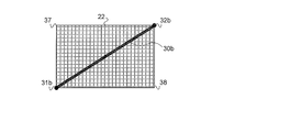
- FIG. 10B is a plan view showing a configuration of Modification 2 of the dirt detection sensor shown in FIG.
- the dirt detection sensor 35 includes a fiber 30b and electrodes 31b and 32b.
- the fibers 30 b are arranged along a straight line connecting two opposing vertices among the four vertices of the square opening.
- the electrode 31b is arranged at the lower left apex and the electrode 32b is arranged at the upper right apex of the filter 22 shown in FIG. 10B, but the electrode 31b is arranged at the apex 37 and at the apex 38.
- the fiber 30b may be arranged so that the electrode 32b is arranged. Since the materials of the fiber 30b and the electrodes 31b and 32b are the same as those of the fiber 30 and the electrodes 31 and 32 described with reference to FIG. 8, detailed descriptions thereof are omitted.
- the dirt detection sensor 35 shown in FIG. 10B is provided so that the fibers 30b straddle the opening of the filter 22 in an oblique direction. The configuration of the dirt detection sensor 35 shown in FIG. 10B is effective regardless of which direction of the wind speed distribution occurs in the vertical direction or the horizontal direction of the opening of the filter 22.
- the fiber passes along the center of gravity of the shape of the opening of the filter 22 and is provided along a straight line connecting two points on the outer periphery of the opening. It has been.
- FIG. 10C is a plan view illustrating a configuration of Modification 3 of the dirt detection sensor illustrated in FIG. 8.
- the dirt detection sensor 35 has two fibers 30c and 30d. Electrodes 31c and 32c and electrodes 31d and 32d are provided at both ends of the fibers 30c and 30d, respectively.
- the fibers 30c and 30d cross each other at the center of gravity of the shape of the opening of the filter 22 while maintaining insulation from each other.
- the control unit 40 performs the stain determination for each of the fibers 30c and 30d. Since the materials of the fibers 30c, 30d and the electrodes 31c, 32c, 31d, 32d are the same as those of the fibers 30 and the electrodes 31, 32 described with reference to FIG.
- the dirt detection sensor 35 shown in FIG. 10C is provided so that the fibers 30c and 30d straddle the opening of the filter 22 in the vertical direction and the horizontal direction. Even if the deviation of the wind speed distribution occurs in any one of the vertical direction and the horizontal direction of the opening of the filter 22, the configuration of the dirt detection sensor 35 shown in FIG. 10B is effective.
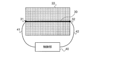
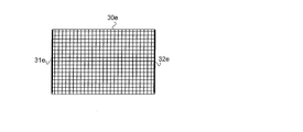
- FIG. 10D is a plan view illustrating a configuration of a fourth modification of the dirt detection sensor illustrated in FIG. 8.
- the dirt detection sensor 35 has a configuration in which a plurality of fibers 30e are arranged in a mesh pattern.
- the whole of the plurality of fibers 30e corresponds to the size of the opening of the filter 22, and the shape thereof is a quadrangle.
- the quadrangle has two sets of two sides facing each other, and the plurality of fibers 30e are arranged along a straight line connecting two sides of each of the two sets.
- the left-right direction in FIG. 10D is referred to as a horizontal direction
- the up-down direction is referred to as a vertical direction.
- Each of the plurality of fibers 30e arranged in the lateral direction has one end connected to the electrode 31e and the other end connected to the electrode 32e.
- the plurality of fibers 30e arranged in the transverse direction intersects the plurality of fibers 30e arranged in the vertical direction at right angles, but maintains insulation from the fibers 30e arranged in different directions.
- the control unit 40 performs contamination determination by applying a voltage between the electrode 31e and the electrode 32e. Since the materials of the fibers 30e and the electrodes 31e and 32e are the same as those of the fibers 30 and the electrodes 31 and 32 described with reference to FIG. 8, detailed descriptions thereof are omitted.
- the dirt detection sensor 35 shown in FIG. 10D is provided so that the plurality of fibers 30e straddle the opening of the filter in the lateral direction.
- the configuration of the dirt detection sensor 35 shown in FIG. 10D is effective.
- the plurality of fibers 30e arranged in each of the vertical direction and the horizontal direction contain carbon nanotubes, the strength against the deflection generated in the filter due to the wind speed increases.
- the control unit 40 performs filter contamination determination based on the current flowing through the plurality of fibers 30e arranged in the horizontal direction, but the determination is performed using the plurality of fibers 30e arranged in the vertical direction. May be.
- the electrodes 31e and 32e provided on the two lateral sides of the plurality of fibers 30e having a square overall shape may be provided on the two vertical sides of the square.
- the fibers 30e of the plurality of fibers 30e in the vertical direction and the plurality of fibers 30e in the horizontal direction may be provided so as to be insulated from the other fibers 30e.
- the control unit 40 it becomes possible for the control unit 40 to apply a voltage to each fiber 30e and measure the current to determine the presence or absence of contamination.
- the dirt detection sensor 35 shown in FIG. 10D may be used as a filter. When the dirt detection sensor 35 shown in FIG. 10D is used as a filter, the fiber 30e has high mechanical strength, so that the life of the filter can be extended.
- the dirt detection sensor 35 is disposed so as to straddle the vertical direction, the horizontal direction, or the oblique direction at the suction port or the outlet of the filter. Accordingly, the control unit 40 can detect dirt due to dust when dust such as dust accumulates on a part of the dirt detection sensor 35 even when the wind speed distribution is uneven.
- the air conditioner of the first embodiment is disposed across the fan 8 that sucks in indoor air, the filter that collects dust in the air sucked by the fan 8, and the air inlet or outlet of the filter. It is determined whether or not the filter is contaminated based on a change in the current flowing through the fiber when a predetermined voltage is applied to the dirt detection sensor 35 and the dirt detection sensor 35 having a fiber containing carbon nanotubes. And a control unit 40.
- the dirt detection sensor 35 including carbon nanotubes having high conductivity and high dust detection sensitivity is arranged so as to straddle the suction port or the outlet of the filter, even if the wind speed distribution of the air suction is uneven, When dust accumulates on a part of the dirt detection sensor 35, dirt generated on the filter can be detected with high sensitivity.
- the dirt detection sensor 35 including carbon nanotubes has high mechanical strength and can be reused after being cleaned. Thereby, the operating cost of an air conditioner can be reduced and the influence on an environment can be reduced.
- the reference value for determining the presence or absence of the deterioration of the filter is provided in advance, regardless of the degree of dust accumulation and the dust accumulation range, It is possible to determine the time for replacement and cleaning.
- the fiber having high conductivity is used for the dirt detection sensor 35, the current flowing through the dirt detection sensor 35 can be small. Therefore, it is not necessary to provide a large-scale voltage generation circuit and current measurement circuit, and the indoor unit for air conditioning can be reduced in size and cost.
- the control unit 40 applies a predetermined voltage to the dirt detection sensor 35 at a constant period to measure the current flowing through the fiber, and the reference current value measured in advance for the measured current. If the rate of change is greater than a predetermined threshold value, it may be determined that the filter is dirty. In this case, by using carbon nanotubes having high conductivity for the dirt detection sensor 35, the change in resistance value when dust adheres to the carbon nanotubes is reflected in the current value flowing through the fiber. The presence or absence of contamination can be determined with higher accuracy.
- the detection unit 45 is further connected to each of the dirt detection sensor 35 and the control unit 40, and the detection unit 45 applies a predetermined voltage to the dirt detection sensor 35 at a constant cycle. Then, the current flowing through the fiber is measured, and the value of the measured current is notified to the control unit 40. The control unit 40 determines the rate of change of the current value notified from the detection unit 45 with respect to the reference current value measured in advance. If the calculated rate of change is greater than a predetermined threshold, it may be determined that the filter is dirty. In this case, since the detection unit 45 that detects the current flowing in the fiber is provided separately from the control unit 40, the detection unit 45 can be provided near the filter.
- the lengths of the wirings 41 and 42 connecting the detection unit 45 and the control unit 40 can be shortened, and the control unit 40 is caused by the change in the current value caused by the change in the resistance value of the wirings 41 and 42. It is possible to suppress erroneous determination of the occurrence of dirt.
- the fibers of the dirt detection sensor 35 are arranged along a straight line passing through the center of gravity of the shape of the opening of the suction port or outlet of the filter and connecting two points on the outer periphery of the opening. It may be.
- the control unit 40 is wider even if the wind speed distribution is uneven. It is possible to detect the contamination of the filter due to the bias in the range.
- the shape of the opening of the suction port or the outlet of the filter is a quadrangle
- the opening has two sets of two sides facing each other
- the fibers of the dirt detection sensor 35 are Of the two sets, they may be arranged along a straight line connecting the center points of two sides of one set.
- the fibers of the dirt detection sensor 35 are arranged so as to straddle the opening of the filter in the vertical direction or the horizontal direction, even when the deviation of the wind speed distribution occurs in the vertical direction or the horizontal direction of the opening of the filter.
- the control unit 40 can detect the occurrence of filter contamination.
- the dirt detection sensor 35 may have two fibers, and the two fibers may cross each other at the center of gravity of the opening while maintaining insulation from each other.
- the two fibers of the dirt detection sensor 35 are arranged so as to straddle the opening of the filter in the vertical direction and the horizontal direction, the deviation of the wind speed distribution is out of the vertical direction and the horizontal direction of the opening of the filter. Even if it occurs in either direction, the control unit 40 can detect the occurrence of contamination of the filter.
- the shape of the opening of the suction port or the outlet of the filter is a quadrangle
- the opening has two sets of two apexes facing each other
- the fibers of the dirt detection sensor 35 are Of the two sets, they may be arranged along a straight line connecting two vertices of one set.
- the control unit 40 can detect the occurrence of contamination of the filter.
- the dirt detection sensor 35 has a plurality of fibers, the shape of the opening of the suction port or the outlet of the filter is a quadrangle, and two sets of two sides facing each other are set.
- the plurality of fibers may be arranged along a straight line connecting two sides of each of the two sets.
- the air conditioner of the first embodiment includes a fan 8 that sucks indoor air, a filter that collects dust in the air, a plurality of fibers including carbon nanotubes arranged in a mesh, and a plurality of A control unit that determines whether or not the filter is contaminated based on a change in current flowing through the fiber when a predetermined voltage is applied to both ends of at least one of the fibers It may be.
- the filter since the filter is composed of fibers containing carbon nanotubes with high dust detection sensitivity, even if the air velocity distribution of air suction is uneven, it occurs in the filter when dust accumulates on a part of the fibers. Dirt can be detected.
- the carbon nanotube has high mechanical strength, the life of the filter is prolonged.
- FIG. 11 is a functional block diagram showing a configuration example of the air conditioner according to Embodiment 2 of the present invention.
- the indoor unit 51 a includes a detection unit 45 connected to each of the dirt detection sensor 35 and the control unit 40 in addition to the configuration shown in FIG. 7.
- the detection unit 45 applies a predetermined voltage between the electrodes 31 and 32 of the dirt detection sensor 35 at a constant period, and measures the current flowing through the fiber 30.
- the voltage applied to the fiber 30 may be supplied via a wiring from a step-down circuit (not shown) provided in the indoor unit body, and a voltage generation circuit (not shown) is provided in the detection unit 45 in advance. It may be supplied from the inside.
- FIG. 12 is a schematic diagram for explaining a method of detecting filter dirt using the dirt detection sensor shown in FIG. 11.
- the detection unit 45 applies a predetermined voltage between the electrodes 31 and 32 of the fiber 30 at a constant period, measures the current flowing through the fiber 30, and notifies the control unit 40 of the measured current value.
- the control unit 40 calculates the rate of change of the notified current value with respect to the reference current value. Then, when the calculated change rate is larger than the threshold value, the control unit 40 determines that the filter 22 is contaminated.
- the dirt detection sensor 35 has been described with the configuration shown in FIG. 8, but any one of the dirt detection sensors of the first to fourth modifications described with reference to FIGS. 10A to 10D is implemented in this embodiment. You may apply to the form 2 of.
- the detection unit 45 that measures the current flowing through the fiber 30 is provided separately from the control unit 40, and thus the detection unit 45 is connected to the filter 22. It becomes possible to provide near. As a result, the length of the wirings 41 and 42 can be shortened. Therefore, it can suppress that the control part 40 misjudges generation
- FIG. 1 the control part 40 misjudges generation
- the dust collecting unit that plays the role of collecting dust is described as a filter.
- the dust collecting unit is a dust collecting filter as disclosed in Patent Document 1. It may be.
- the air conditioning indoor unit is a packaged air conditioner indoor unit.
- the air conditioning indoor unit of the present invention is not limited to a packaged air conditioner.
- the air conditioner to which the present invention is applied may be an air cleaner.
- the heat exchanger 10 and the outdoor unit 52 may not be provided.
- 1 makeup panel 1a opening, 2 operation panel, 3 front side suction port panel, 3a front side panel, 4 intake hole, 5 fan case flange, 6 back side panel, 6a back side panel, 7 back side suction port, 8 Fan, 9 motor, 10, 16a, 16b heat exchanger, 11 fan side pulley, 12 motor side pulley, 15 drain pan, 17 back side suction port, 20, 21 front side suction port, 22, 25a, 25b filter, 22a frame , 22b opening, 27 operation part, 30, 30a-30e fiber, 31, 31a-31e electrode, 32, 32a-32e electrode, 35 dirt detection sensor, 37, 38 apex, 40 control part, 41, 42 wiring, 45 Detection unit, 51, 51a indoor unit, 52 outdoor unit.
Landscapes
- Engineering & Computer Science (AREA)
- Chemical & Material Sciences (AREA)
- Combustion & Propulsion (AREA)
- Mechanical Engineering (AREA)
- General Engineering & Computer Science (AREA)
- Physics & Mathematics (AREA)
- Thermal Sciences (AREA)
- Electrochemistry (AREA)
- Chemical Kinetics & Catalysis (AREA)
- Health & Medical Sciences (AREA)
- Life Sciences & Earth Sciences (AREA)
- Analytical Chemistry (AREA)
- Biochemistry (AREA)
- General Health & Medical Sciences (AREA)
- General Physics & Mathematics (AREA)
- Immunology (AREA)
- Pathology (AREA)
- Air Conditioning Control Device (AREA)
Abstract
本発明の課題は、空気の吸い込みの風速分布に偏りがあっても塵埃収集部に発生する汚れを感度よく検知可能にした空調機を提供することにある。 本発明の空調機は、室内の空気を吸い込むファンと、ファンが吸い込んだ空気中の塵埃を収集する塵埃収集部と、塵埃収集部における空気の吸込口または吹出口をまたいで配置された、カーボンナノチューブを含む繊維を備えた汚れ検知センサーと、予め決められた電圧を汚れ検知センサーに印加したときの繊維に流れる電流の変化に基づいて塵埃収集部に汚れが発生したか否かを判定する制御部と、を有するものである。
Description
本発明は、空気の汚れを検知する機能を備えた空調機に関する。
空調用室内機には、室内の空気中の埃を収集するフィルターと、室内から吸い込んだ埃を検知する埃検知センサーとが設けられているものがある。
埃を収集するフィルターには、繊維が網目状に編み込まれたフィルターが多く使用されているが、埃を帯電して収集するフィルターが使用されることもある。埃を帯電して収集する集塵フィルターの一例が特許文献1に開示されている。
埃検知センサーの一例が特許文献2に開示されている。特許文献2に開示された光学式埃センサーは、検出領域に光を照射し、検出領域を通過する埃からの反射光を検知することで、検出領域を通過する埃の数をカウントし、カウント数が一定量を超えると、汚れが発生したと判定する。
埃を収集するフィルターには、繊維が網目状に編み込まれたフィルターが多く使用されているが、埃を帯電して収集するフィルターが使用されることもある。埃を帯電して収集する集塵フィルターの一例が特許文献1に開示されている。
埃検知センサーの一例が特許文献2に開示されている。特許文献2に開示された光学式埃センサーは、検出領域に光を照射し、検出領域を通過する埃からの反射光を検知することで、検出領域を通過する埃の数をカウントし、カウント数が一定量を超えると、汚れが発生したと判定する。
また、室内の空気中の汚れの原因となる物質は、埃だけでなく、化学物質も考えられる。化学物質のうち、一酸化炭素および水素等のガスのセンサーとして、MEMS(Micro-Electro-Mechanical Systems)技術を用いたセンサーが知られている。以下では、MEMS技術を用いたセンサーを「MEMSセンサー」と称する。
MEMSセンサーは、シリコン基板上に金属酸化物が形成された構造を有する。MEMSセンサーは、金属酸化物の表面がガス濃度の変化を電圧出力の変動として検知し、一定量の変化を検知すると、汚れが発生したと判定する。MEMSセンサーの一例が特許文献3に開示されている。
MEMSセンサーは、シリコン基板上に金属酸化物が形成された構造を有する。MEMSセンサーは、金属酸化物の表面がガス濃度の変化を電圧出力の変動として検知し、一定量の変化を検知すると、汚れが発生したと判定する。MEMSセンサーの一例が特許文献3に開示されている。
特許文献2に開示された光学式埃センサーは検出領域を通過する埃の粒子量からフィルターの汚れ度合いを判定しているが、光学式埃センサーをどこに設置するかが重要である。例えば、室内から空調用室内機に吸い込まれる空気の吸い込みによる風速に偏りがあると、フィルターの一部にだけ埃が早く堆積してしまうことになる。埃が堆積しやすい位置に光学式埃センサーを設置しなければ、フィルターの汚れ発生の検知が遅くなってしまう。この問題は特許文献3に開示されたMEMSセンサーについても同様である。特許文献2および3に開示されたセンサーにおいては、センサー設置位置の決定が困難という課題が存在する。特許文献1に開示された集塵フィルターにセンサーを設置する場合にも、センサーの設置位置を決定するのは困難である。
また、特許文献2に開示された光学式埃センサーは反射光の強度の弱い埃の検出感度が悪く、特許文献3に開示されたMEMSセンサーは検知対象が金属酸化物の金属の種類で決まってしまい、検知対象以外のガスには検知感度が悪いという問題があった。
また、特許文献2に開示された光学式埃センサーは反射光の強度の弱い埃の検出感度が悪く、特許文献3に開示されたMEMSセンサーは検知対象が金属酸化物の金属の種類で決まってしまい、検知対象以外のガスには検知感度が悪いという問題があった。
本発明は、上記のような課題を解決するためになされたもので、空気の吸い込みの風速分布に偏りがあっても塵埃収集部に発生する汚れを感度よく検知可能にした空調機を提供することにある。
本発明に係る空調機は、室内の空気を吸い込むファンと、ファンが吸い込んだ空気中の塵埃を収集する塵埃収集部と、塵埃収集部における空気の吸込口または吹出口をまたいで配置された、カーボンナノチューブを含む繊維を備えた汚れ検知センサーと、予め決められた電圧を汚れ検知センサーに印加したときの繊維に流れる電流の変化に基づいて塵埃収集部に汚れが発生したか否かを判定する制御部と、を有するものである。
本発明は、塵埃の検出感度の高いカーボンナノチューブを含むセンサーが塵埃収集部の空気の吸込口または吹出口をまたぐように設けられているので、空気の吸い込みの風速分布に偏りがあっても塵埃収集部に発生する汚れを感度よく検知できる。
実施の形態1.
本実施の形態1では、種々の室内機の中でも、パッケージエアコンと称される空調機の室内機の場合で説明する。パッケージエアコンは、オフィスおよび店舗などにおいて、空調対象の部屋の用途および体積に応じて室内機の数および種類をユーザが選択できるようにした空調機である。室内機の種類には、例えば、床置形、天井カセット形および天吊形がある。
本実施の形態1では、室内機の種類が床置形である場合で説明する。また、本実施の形態1では、室内機が1台の場合で説明するが、室内機は複数であってもよい。
本実施の形態1では、種々の室内機の中でも、パッケージエアコンと称される空調機の室内機の場合で説明する。パッケージエアコンは、オフィスおよび店舗などにおいて、空調対象の部屋の用途および体積に応じて室内機の数および種類をユーザが選択できるようにした空調機である。室内機の種類には、例えば、床置形、天井カセット形および天吊形がある。
本実施の形態1では、室内機の種類が床置形である場合で説明する。また、本実施の形態1では、室内機が1台の場合で説明するが、室内機は複数であってもよい。
(室内機の外観正面の構成)
本実施の形態1の空調用室内機の構成を説明する。
図1は、本発明の実施の形態1の空調用室内機の外観の一例を示す正面図である。図1の一部は透視図になっており、透視された構成を破線で示す。
図1に示す室内機の外観形状は箱状の直方体である。図1は室内機が床面の上に設置されている状態を示す。図1に示す室内機において、床面に垂直な方向を「縦方向」とし、床面に平行な方向を「横方向」とする。
図1に示すように、室内機の正面は、上側が化粧パネル1で覆われ、下側が正面側吸込口パネル3で覆われている。
化粧パネル1の一部に開口部1aが設けられ、開口部1aに操作パネル2が配置されている。操作パネル2は、空調機の設定を含む動作状態および室内の温度を含む環境状態を表示する表示部(不図示)と、ユーザが空調機への設定および動作を指示するための操作部(不図示)とを有する。操作パネル2の表示部にタッチパネルが設けられ、操作部の機能の一部をタッチパネルに実行させるようにしてもよい。
図1に示すように、正面側吸込口パネル3には、複数の吸気穴4が設けられている。図1に示す例では、縦方向に等間隔に配置された13個の吸気穴4からなる列が横方向に等間隔で4列設けられている。これら複数の吸気穴4(13個×4個の吸気穴4)を含む開口を正面側吸込口20とする。
吸気穴4の種類は、グリル穴、パンチ穴およびスリットなどである。図1に示す吸気穴4はスリットの一種である。正面側吸込口パネル3の材質は、例えば、鉄、ステンレス、アルミニウムおよびプラスチックである。
室内機の上部には、熱変換後の空気を室内に送出する吹出口を備えたファンケースフランジ5が設けられている。
なお、室内機が、正面側から空気の吸い込みを行う正面側吸込み仕様ではなく、背面側から空気の吸い込みを行う背面側吸込み仕様の場合については、後述する。
吸気穴4の種類は、グリル穴、パンチ穴およびスリットなどである。図1に示す吸気穴4はスリットの一種である。正面側吸込口パネル3の材質は、例えば、鉄、ステンレス、アルミニウムおよびプラスチックである。
室内機の上部には、熱変換後の空気を室内に送出する吹出口を備えたファンケースフランジ5が設けられている。
なお、室内機が、正面側から空気の吸い込みを行う正面側吸込み仕様ではなく、背面側から空気の吸い込みを行う背面側吸込み仕様の場合については、後述する。
(室内機の外観背面の構成)
図2は、図1に示した空調用室内機の外観の一例を示す背面図である。図2の一部は透視図になっており、透視された構成を破線で示す。
図2に示すように、室内機の背面は背面側パネル6で覆われている。背面側パネル6には、床面に近い側に背面側吸込口7が設けられている。
背面側吸込口7には、ビニール袋など、埃より大きいものを吸い込んでしまうことを防ぐために格子(不図示)が設けられている。格子の材質は、鉄およびアルミニウムなどの金属に限らず、プラスチックなどの非金属であってもよい。背面側吸込口7の横方向の長さである幅をW1とする。
図2は、図1に示した空調用室内機の外観の一例を示す背面図である。図2の一部は透視図になっており、透視された構成を破線で示す。
図2に示すように、室内機の背面は背面側パネル6で覆われている。背面側パネル6には、床面に近い側に背面側吸込口7が設けられている。
背面側吸込口7には、ビニール袋など、埃より大きいものを吸い込んでしまうことを防ぐために格子(不図示)が設けられている。格子の材質は、鉄およびアルミニウムなどの金属に限らず、プラスチックなどの非金属であってもよい。背面側吸込口7の横方向の長さである幅をW1とする。
(1枚の熱交換器を有する室内機の内部構成)
図3は、図1に示した空調用室内機が1枚の熱交換器を有する場合の内部構造の一例を示す正面図である。図4は、図3に示した空調用室内機の内部構造の一例を示す側面透視図である。図3および図4は、室内機が1枚の熱交換器を有する場合の構成を示す。
図3は、図1に示した室内機から、図1に示した化粧パネル1および正面側吸込口パネル3と、図4に示すフィルター22を取り外した状態を示す。
熱交換器10の下側には、熱交換器10で結露した水を受けるためのドレンパン15が設けられている。熱交換器10の上側には、室内の空気を室内機内に吸い込むファン8と、ファン8を回転駆動するモーター9とが設けられている。
図3は、図1に示した空調用室内機が1枚の熱交換器を有する場合の内部構造の一例を示す正面図である。図4は、図3に示した空調用室内機の内部構造の一例を示す側面透視図である。図3および図4は、室内機が1枚の熱交換器を有する場合の構成を示す。
図3は、図1に示した室内機から、図1に示した化粧パネル1および正面側吸込口パネル3と、図4に示すフィルター22を取り外した状態を示す。
熱交換器10の下側には、熱交換器10で結露した水を受けるためのドレンパン15が設けられている。熱交換器10の上側には、室内の空気を室内機内に吸い込むファン8と、ファン8を回転駆動するモーター9とが設けられている。
熱交換器10は、熱交換器10および室外機(不図示)間で冷媒が循環する配管(不図示)と複数のフィン(不図示)とが一体になって構成されたものである。図3および図4では、熱交換器10全体の外観を、板状の直方体に簡略化して示している。
図4に示すように、熱交換器10は、縦方向を基準にして床面側に傾いている。図4に示す熱交換器10の上下の辺に注目すると、上側の辺が室内機の正面側のパネルに接近し、下側の辺が室内機の背面側のパネルに接近している。
図4に示す構成例では、熱交換器10にフィルター22が取り付けられている。フィルター22は、空気中の塵埃を収集する役目を果たす塵埃収集部の一例である。
ドレンパン15は、ドレンパン15に溜まった水を排出するための配管(不図示)と接続されている。
図4に示すように、熱交換器10は、縦方向を基準にして床面側に傾いている。図4に示す熱交換器10の上下の辺に注目すると、上側の辺が室内機の正面側のパネルに接近し、下側の辺が室内機の背面側のパネルに接近している。
図4に示す構成例では、熱交換器10にフィルター22が取り付けられている。フィルター22は、空気中の塵埃を収集する役目を果たす塵埃収集部の一例である。
ドレンパン15は、ドレンパン15に溜まった水を排出するための配管(不図示)と接続されている。
モーター9の回転軸の先端にはモーター側プーリー12が取り付けられている。ファン8の回転軸の先端にはファン側プーリー11が取り付けられている。モーター側プーリー12とファン側プーリー11にはベルトがかけられている。ファン8の回転軸には複数のフィンが取り付けられている。モーター9の回転軸が回転すると、その回転駆動力がモーター側プーリー12およびベルトを介してファン側プーリー11に伝達する。ファン側プーリー11が回転すると、ファン8の回転軸に取り付けられた複数のフィンが回転する。これにより、室内の空気が室内機に吸い込まれ、熱交換後の空気が吹出口から室内に送出される。
正面側吸込口20の縦方向の寸法をL1とし、背面側吸込口7の縦方向の寸法をH1とする。図3および図4に示したような、1枚の熱交換器10を有する室内機の場合では、正面側吸込口20の縦方向の寸法L1を300~1500[mm]とし、背面側吸込口7の幅W1を500~2500[mm]とし、背面側吸込口7の縦方向の寸法H1を50~500[mm]としている。また、背面側吸込口7は、背面側吸込口7の下端がドレンパン15の上縁から上側に5~200[mm]の範囲に位置するように、設けられている。このように、正面側および背面側の両方の吸込口を使用する場合に、風量を確保し、風速分布を決定するように、各寸法が設定されている。
なお、図4に示す構成では、熱交換器10にフィルター22が取り付けられているが、背面側吸込口7にもフィルターが設けられていてもよい。
(背面側吸込み仕様の構成)
ここで、室内機の仕様が、正面側吸込み仕様ではなく、背面側吸込み仕様の場合について説明する。
背面側吸込み仕様の場合、図1に示す正面側吸込口パネル3の場所には、吸気穴4が設けられていないパネルが取り付けられる。吸気穴4が設けられていないパネルの材質は、例えば、ステンレス、アルミニウムおよびプラスチックである。
図2に示した背面側吸込口7をダクトフランジおよびシャッター・ノックアウトなどの形態に変更することで、背面側吸込口の面積および位置の変更が容易になる。
背面側吸込み仕様の場合、図4に示したフィルター22の代わりに、背面側吸込口にフィルターが設けられていてもよい。
ここで、室内機の仕様が、正面側吸込み仕様ではなく、背面側吸込み仕様の場合について説明する。
背面側吸込み仕様の場合、図1に示す正面側吸込口パネル3の場所には、吸気穴4が設けられていないパネルが取り付けられる。吸気穴4が設けられていないパネルの材質は、例えば、ステンレス、アルミニウムおよびプラスチックである。
図2に示した背面側吸込口7をダクトフランジおよびシャッター・ノックアウトなどの形態に変更することで、背面側吸込口の面積および位置の変更が容易になる。
背面側吸込み仕様の場合、図4に示したフィルター22の代わりに、背面側吸込口にフィルターが設けられていてもよい。
(2枚の熱交換器を有する室内機の内部構成)
図3および図4を参照して、1枚の熱交換器を有する室内機の構成の一例を説明したが、図5を参照して、2枚の熱交換器を有する室内機の構成の一例を説明する。
図5は、図1に示した空調用室内機が2枚の熱交換器を有する場合の内部構造の一例を示す側面透視図である。
室内機は2枚の熱交換器16a、16bを有する。図5に示すように、熱交換器16aおよび熱交換器16bは、室内機の側面側から見て、V字、L字またはνの字状に配置されている。
図5に示すように、正面側パネル3aに正面側吸込口21が設けられ、背面側パネル6aに背面側吸込口17が設けられている。正面側吸込口21は、図1に示した正面側吸込口20と同様に、複数の吸気穴4を有する。背面側吸込口17は図4に示した背面側吸込口7よりも高い位置に設けられている。また、背面側吸込口17の縦方向の寸法をH2とすると、H2>H1の関係になっている。
正面側吸込口21の室内機側にはフィルター25aが設けられ、背面側吸込口17の室内機側にはフィルター25bが設けられている。フィルター25a、25bは塵埃収集部の一例である。図5に示す構成例では、熱交換器16a、16bにはフィルターが設けられていない。
図5に示したような、2枚の熱交換器16a、16bを有する室内機の場合では、背面側吸込口17の幅を背面側吸込口7の幅W1と同じ500~2500[mm]とし、背面側吸込口17の縦方向の寸法H2を30~1000[mm]としている。このように、正面側および背面側の両方の吸込口を使用する場合に、風量を確保し、最適な風速分布を決定するように、各寸法が設定されている。
また、図5に示したような、2枚の熱交換器16a、16bを有する室内機の場合、背面側吸込口17は、背面側吸込口17の下端がドレンパン15の上縁から上側に30~1000[mm]の範囲に位置するように、設けられている。このように、正面側および背面側の両方の吸込口を使用する場合に、吸込み空気の圧力損失を低減して風量を確保し、最適な風速分布を決定するように、背面側吸込口17の位置が設定されている。
また、図5に示す正面側吸込口21の縦方向の寸法をL2とすると、正面側吸込口21の縦方向の寸法L2を300~1500[mm]とする。図5に示したような、2枚の熱交換器16a、16bを有する室内機の場合に、吸込み空気の圧力損失を低減して風量を確保し、最適な風速分布を決定するように、正面側吸込口21の縦方向の寸法が設定されている。
(フィルター22の構成)
図4に示したフィルター22の構成を説明する。図6は、図4に示したフィルターの一構成例を示す平面図である。
図6に示すように、フィルター22は、枠22aと、開口部22bとを有する。開口部22bには、複数の繊維が交差するように網目状に設けられている。室内から空気と共に吸い込まれた塵埃は開口部22bに網目状に設けられた繊維に引っかかる。
図6はフィルター22の正面側吸込口20側を示し、図6に示す開口部22bはフィルター22の空気の吸込口に相当する。開口部22bの裏側(不図示)がフィルター22の空気の吹出口に相当する。
なお、図6以降の図に示すフィルター22においては、開口部22bを図に示し、枠22aを図に示すことを省略する。
フィルター22の寸法は、縦方向、横方向および奥行のそれぞれの長さが50mm以上であることが望ましい。フィルター25a、25bを含む他のフィルターについても、縦方向、横方向および奥行のそれぞれの寸法は50mm以上であることが望ましい。
(空調機の機能の説明)
図7は、本発明の実施の形態1の空調機の一構成例を示す機能ブロック図である。
本実施の形態1では、汚れ検知方法について詳しく説明し、一般的な空調制御の機能に関する構成とその詳細な説明を省略する。例えば、温度および湿度を検知するセンサーが室内機に設けられているが、その構成を図に示すことを省略している。
本実施の形態1の空調機は、室内機51および室外機52を有する。
室内機51は、モーター9と、汚れ検知センサー35と、操作部27と、制御部40とを有する。制御部40は、モーター9、汚れ検知センサー35、操作部27および室外機52のそれぞれと接続されている。熱交換器10は、上述したように、室外機52と配管(不図示)で接続されている。操作部27は操作パネル2に含まれる。汚れ検知センサー35が図4に示したフィルター22の吸込口に取り付けられているものとする。
制御部40は、予め決められた手順にしたがって処理を実行するマイクロコンピューター(不図示)と、予め決められた電圧および閾値ならびに測定される基準電流値を記憶する不揮発性メモリ(不図示)とを有する。不揮発性メモリが記憶する電圧、基準電流値および閾値は、後で説明する汚れ検知判定処理で使用される値である。
制御部40は、操作部27を介して入力される指示にしたがってモーター9および室外機52を制御する。
制御部40は、一定の周期で、予め決められた電圧を汚れ検知センサー35に印加して汚れ検知センサー35に流れる電流を測定し、測定した電流の変化に基づいてフィルター22が汚れているか否かを判定する。一定の周期とは、例えば、1~2[回/日]である。汚れ検知センサー35に印加される電圧は、外部から供給される交流電圧が電圧変換回路(不図示)で直流電圧に変換された後、降圧回路(不図示)によって生成される。
なお、制御部40は、図1に示す室内機が複数設けられている場合、他の室内機の空調制御も行うリモートコントローラとしての機能を備えていてもよい。
(汚れ検知センサー35の構成)
図7に示した汚れ検知センサー35の構成を説明する。
図8は、本発明の実施の形態1の空調機に設けられた汚れ検知センサーの一構成例を示す図である。ここでは、図7に示した汚れ検知センサー35が図4に示したフィルター22の吸込口側の開口部に取り付けられた場合で説明するが、吹出口側の開口部に取り付けられてもよい。また、汚れ検知センサー35が取り付けられるフィルターはフィルター22に限定されない。汚れ検知センサー35がフィルター25aおよびフィルター25bに取り付けられてもよい。
汚れ検知センサー35は、図8に示すように、カーボンナノチューブを含む繊維30を備えた構成である。繊維30の両端には、電極31、32が設けられている。電極31、32の材質は、例えば、銅である。
図8に示す構成例では、繊維30は、フィルター22において、四角形の開口部の4辺のうち、横方向に対向する2辺のそれぞれの中心を結ぶ直線に沿って配置されている。フィルター22の開口部は対向する2辺の組を2組有しているが、図8に示す繊維30は、横方向に対向する組の2辺の中心点を結んでいる。
図8に示す汚れ検知センサー35は、繊維30がフィルター22の開口部を横方向にまたぐように設けられている。風速分布の偏りがフィルター22の開口部の横方向に生じた場合、図8に示す汚れ検知センサー35の構成は有効である。
(汚れ検知センサー35の構成)
繊維30の材質は、カーボンナノチューブを50~100%含有する繊維である。繊維30が「カーボンナノチューブ100%の繊維」でない場合として、例えば、炭素繊維にカーボンナノチューブが添加されたものが考えられる。以下では、カーボンナノチューブを含有する炭素繊維を「ナノチューブ含有炭素繊維」と称する。
繊維30は、1本の繊維で構成されてもよく、複数の繊維が縄のようにより合わされて1本の束になった構成であってもよい。例えば、単層のカーボンナノチューブの場合、製造過程において、生成された複数のカーボンナノチューブはファンデルワールス力によって互いに引き合い、バンドル(束)と呼ばれる構造になりやすい。このバンドルが繊維30であってもよい。
繊維30はカーボンナノチューブを含んでいるので機械的強度が高い。さらに繊維30が複数本の繊維で構成される場合、機械的強度が増し、空気の吸い込み力に起因するたわみ等によるセンサーの感度低下を防ぐことができる。室内からの送風および塵埃等による、フィルターのたわみは、汚れ検知センサー35への影響は小さい。たわみ等による繊維30の伸び率は0.1~2%程度であるが、汚れ検知の感度への影響は、それ以下である。
繊維30の太さは1μm以上10mm以下の範囲を取り得る。太さが1μmの場合とは、例えば、カーボンナノチューブ1本の場合である。太さが10mmの場合は、例えば、上記バンドルまたはナノチューブ含有炭素繊維の場合である。繊維30には、上記のように、太さが1μm~10mmの繊維を用いることが可能であるが、空調機の管理者が視認しやすい太さであって、かつ空気抵抗の増加を防ぐ太さであることが望ましい。繊維30の太さとして、管理者が視認しやすい太さが必要なのは、繊維30が切れてしまった場合、繊維30が切れていることを管理者に視覚的に認識できるようにするためである。
次に、繊維30の電気伝導率(導電率)について説明する。
単層カーボンナノチューブは、グラフェンと呼ばれる、炭素の1層の原子層が筒状に構成されたものであるが、その結合の仕方により、導体または半導体の性質になる。以下では、導体の性質を有するカーボンナノチューブを金属ナノチューブと称し、半導体の性質を有するカーボンナノチューブを半導体ナノチューブと称する。
例えば、カーボンナノチューブをCVD(Chemical Vapor Deposition)法で生成した場合、生成されたカーボンナノチューブには、金属ナノチューブと半導体ナノチューブが混在する。金属ナノチューブと半導体ナノチューブの分離方法として、例えば、界面活性剤を用いた遠心分離法(密度勾配遠心分離法)が知られている。半導体ナノチューブから分離した金属ナノチューブの導電率は銅の導電率の1000倍である。
繊維30が全て金属ナノチューブで構成される場合、繊維30の導電率は銅の1000倍となる。繊維30を全て金属ナノチューブで構成しなくても、繊維30に占める金属ナノチューブの割合を高くして、繊維30の導電率が銅の導電率よりも小さくなるようにしてもよい。この場合、繊維30は空気中の汚れの原因になる物質を検知する感度が銅よりもよくなる。また、検知対象の塵埃の種類に応じて、繊維30に含まれる半導体ナノチューブの割合を調節して、検知感度を調整することも可能となる。
汚れ検知センサー35の検知対象は、埃に限らず、カビであってもよく、また、工場で発生する粉塵であってもよい。例えば、空調機が設置される場所がお茶工場である場合、茶粉が検知対象であってもよい。空調機が設置される場所が金属加工工場である場合、金属等の摩耗粉が検知対象であってもよい。摩耗粉とは、例えば、金属粉である。
なお、繊維30に用いられるカーボンナノチューブが単層の場合で説明したが、カーボンナノチューブは多層であってもよい。
なお、繊維30に用いられるカーボンナノチューブが単層の場合で説明したが、カーボンナノチューブは多層であってもよい。
(汚れ検出方法)
図8に示した汚れ検知センサー35を用いてフィルター22の汚れを検知する方法を説明する。
図9は、図8に示した汚れ検知センサーを用いてフィルターの汚れを検知する方法を説明するための模式図である。繊維30は繊維30の導電率が銅の導電率よりも高い値になるように構成されているものとする。
図9に示すように、汚れ検知センサー35の2つの電極31、32のうち、一方の電極31が配線41を介して制御部40と接続され、他方の電極32が配線42を介して制御部40と接続されている。
制御部40は、一定の周期で汚れ検知センサー35の2つの電極31、32間に配線41、42を介して電圧を印加し、汚れ検知センサー35に流れる電流を測定する。そして、制御部40は、測定した電流について基準電流値に対する変化率を算出し、変化率が予め決められた閾値よりも大きいと、フィルター22に汚れが発生していると判定する。
ここで、制御部40が実行する、汚れ判定方法を説明する。
繊維30の電極31と電極32の間に印加される電圧をVとし、繊維30の抵抗をRfとする。また、配線41、42、電極31、32のそれぞれの抵抗値をRW1、RW2、Re1、Re2とすると、制御部40が測定する電流値I0は、次の式(1)に対応する。なお、電極と配線間の接触抵抗等を無視する。
I0=V/(Rf+RW1+RW2+Re1+Re2)・・・式(1)
電流値I0が基準電流値となる。制御部40は基準電流値として電流値I0を不揮発性メモリ(不図示)に保存する。繊維30に汚れが付着して抵抗値がRfからRf+ΔRに変化し、他の抵抗素子の値が変化しなければ、制御部40が測定する電流値I1は、次の式(2)に対応する。
I1=V/(Rf+ΔR+RW1+RW2+Re1+Re2)・・・式(2)
閾値をTHとすると、制御部40は、|I0-I1|/I0>THの関係を満たす場合、フィルター22に汚れが発生したと判定する。
なお、制御部40は、フィルター22の洗浄および交換の度に基準電流値の測定を実行し、記憶する基準電流値を更新することが望ましい。
汚れ検知センサー35の機械的強度は高いが、フィルター22の長期間の使用に伴って、繊維30の基準電流値が少しずつ変化する。そこで、フィルター22が劣化しているか否かの判定基準となる基準電流値を予め制御部40の不揮発性メモリ(不図示)に登録しておいてもよい。この基準電流値をフィルター基準と称する。この場合、制御部40は、汚れ判定を実行する前に、測定した基準電流値がフィルター基準よりも大きい場合、フィルター22の交換または洗浄を促すメッセージを操作パネル2の表示部(不図示)に表示する。このようにして、管理者はフィルター22の交換および洗浄の時期を判定することが可能となる。
また、管理者は閾値THの値を調整することで、検知感度を調整してもよい。
また、繊維30に含まれるカーボンナノチューブにおける半導体ナノチューブの割合を高く設定する場合が考えられる。その場合の一例を説明する。
本実施の形態1の空調機が金属加工工場に設置される場合、金属粉を検知対象とする。この場合、繊維30に含まれるカーボンナノチューブに占める半導体ナノチューブの割合が金属ナノチューブよりも高くなるように繊維30を構成する。フィルター22に付着する金属粉が増加すると、繊維30の半導体ナノチューブに金属粉が付着し、繊維30に電流が流れやすくなる。この場合でも、制御部40は、繊維30に流れる電流の変化に基づいて、フィルター22に汚れが発生したか否かを判定することが可能となる。
本実施の形態1の空調機が金属加工工場に設置される場合、金属粉を検知対象とする。この場合、繊維30に含まれるカーボンナノチューブに占める半導体ナノチューブの割合が金属ナノチューブよりも高くなるように繊維30を構成する。フィルター22に付着する金属粉が増加すると、繊維30の半導体ナノチューブに金属粉が付着し、繊維30に電流が流れやすくなる。この場合でも、制御部40は、繊維30に流れる電流の変化に基づいて、フィルター22に汚れが発生したか否かを判定することが可能となる。
また、汚れ判定方法に電流値を用いる場合で説明したが、制御部40は繊維30の抵抗値の変化に基づいて判定してもよい。この場合、繊維30以外の抵抗素子の値が制御部40の不揮発性メモリ(不図示)に予め登録されているものとする。印加する電圧の値が電圧発生回路の不具合により予め決められた値からずれてしまっても、ずれた電圧の値が電流値に反映されるため、算出される抵抗値に電圧の変化の影響を及ぼさずに済む。式(1)および式(2)について、左辺を抵抗値とし、右辺を(電圧/電流)に変形すると、電圧に生じたずれと電流値に生じたずれが相殺されることがわかる。繊維30の導電率を高くして検知感度を高く設定している場合、電圧の変動による影響を抑制できる抵抗値で判定することが望ましい。
(汚れ検知センサー35の変形例1)
図10Aは、図8に示した汚れ検知センサーの変形例1の構成を示す平面図である。
図10Aに示すように、汚れ検知センサー35は、繊維30aと、電極31a、32aとを有する。繊維30aは、フィルター22において、四角形の開口部の4辺のうち、縦方向に対向する2辺のそれぞれの中心を結ぶ直線に沿って配置されている。フィルター22の開口部は対向する2辺の組を2組有しているが、図10Aに示す繊維30aは、縦方向に対向する組の2辺の中心点を結んでいる。
繊維30aおよび電極31a、32aのそれぞれの材質は図8を参照して説明した繊維30および電極31、32のそれぞれと同様なため、その詳細な説明を省略する。
図10Aに示す汚れ検知センサー35は、繊維30aがフィルター22の開口部を縦方向にまたぐように設けられている。風速分布の偏りがフィルター22の開口部の縦方向に生じた場合、図10Aに示す汚れ検知センサー35の構成は有効である。
(汚れ検知センサー35の変形例2)
図10Bは、図8に示した汚れ検知センサーの変形例2の構成を示す平面図である。
図10Bに示すように、汚れ検知センサー35は、繊維30bと、電極31b、32bとを有する。繊維30bは、フィルター22において、四角形の開口部の4つの頂点のうち、対向する2頂点を結ぶ直線に沿って配置されている。
図10Bに示す構成例では、図10Bに示すフィルター22の左下の頂点に電極31bが配置され、右上の頂点に電極32bが配置されているが、頂点37に電極31bが配置され、頂点38に電極32bが配置されるように繊維30bが配置されてもよい。
繊維30bおよび電極31b、32bのそれぞれの材質は図8を参照して説明した繊維30および電極31、32のそれぞれと同様なため、その詳細な説明を省略する。
図10Bに示す汚れ検知センサー35は、繊維30bがフィルター22の開口部を斜め方向にまたぐように設けられている。風速分布の偏りがフィルター22の開口部の縦方向および横方向のうち、いずれの方向に生じても、図10Bに示す汚れ検知センサー35の構成は有効である。
図8に示した汚れ検知センサー35および変形例1~2の汚れ検知センサー35では、繊維がフィルター22の開口部の形状の重心を通り、開口部の外周の2点を結ぶ直線に沿って設けられている。
(汚れ検知センサー35の変形例3)
図10Cは、図8に示した汚れ検知センサーの変形例3の構成を示す平面図である。
汚れ検知センサー35は2本の繊維30c、30dを有する。繊維30c、30dのそれぞれの両端には、電極31c、32cと電極31d、32dがそれぞれ設けられている。繊維30c、30dは、互いに相手との絶縁性を保ってフィルター22の開口部の形状の重心で交差している。制御部40は繊維30c、30dを1本ずつ汚れ判定を行う。
繊維30c、30dおよび電極31c、32c、31d、32dのそれぞれの材質は図8を参照して説明した繊維30および電極31、32のそれぞれと同様なため、その詳細な説明を省略する。
図10Cに示す汚れ検知センサー35は、繊維30c、30dがフィルター22の開口部を縦方向および横方向にまたぐように設けられている。風速分布の偏りがフィルター22の開口部の縦方向および横方向のうち、いずれかの方向に生じても、図10Bに示す汚れ検知センサー35の構成は有効である。
(汚れ検知センサー35の変形例4)
図10Dは、図8に示した汚れ検知センサーの変形例4の構成を示す平面図である。
図10Dに示すように、汚れ検知センサー35は複数の繊維30eが網目状に配置された構成である。複数の繊維30eの全体は、フィルター22の開口部の大きさに対応しており、その形状は四角形である。四角形は対向する2辺の組を2組有し、複数の繊維30eは、2組のそれぞれの組の2辺を結ぶ直線に沿って配置されている。以下では、図10Dの左右方向を横方向と称し、上下方向を縦方向と称する。
横方向に配置された複数の繊維30eのそれぞれは、一方の端が電極31eと接続され、他方の端が電極32eと接続されている。横方向に配置された複数の繊維30eは、縦方向に配置された複数の繊維30eと直角に交差しているが、配置された方向の異なる繊維30eとは絶縁性を保っている。
制御部40は、電極31eと電極32e間に電圧を印加することで汚れ判定を行う。
繊維30eおよび電極31e、32eのそれぞれの材質は図8を参照して説明した繊維30および電極31、32のそれぞれと同様なため、その詳細な説明を省略する。
図10Dに示す汚れ検知センサー35は、複数の繊維30eがフィルターの開口部を横方向にまたぐように設けられている。風速分布の偏りがフィルターの開口部全体のいずれかに生じる場合、図10Dに示す汚れ検知センサー35の構成は有効である。
また、縦方向と横方向のそれぞれに複数配置された繊維30eがカーボンナノチューブを含んでいるため、風速によってフィルターに生じるたわみに対する強度が増す。
また、縦方向と横方向のそれぞれに複数配置された繊維30eがカーボンナノチューブを含んでいるため、風速によってフィルターに生じるたわみに対する強度が増す。
なお、図10Dに示す構成では、制御部40が、横方向に配置された複数の繊維30eに流れる電流に基づいてフィルターの汚れ判定を行うが、縦方向に配置された複数の繊維30eで判定してもよい。例えば、図10Dに示す構成において、全体形状が四角形の複数の繊維30eの横方向の2つの辺に設けられた電極31e、32eを、四角形の縦方向の2つの辺に設ければよい。
また、縦方向の複数の繊維30eと横方向の複数の繊維30eのそれぞれの繊維30eが互いに他の繊維30eと絶縁性を保つように設けられていてもよい。この場合、制御部40が1本の繊維30e毎に電圧を印加して電流を測定し、汚れ発生の有無を判定することが可能となる。
また、図10Dに示す汚れ検知センサー35をフィルターとして使用してもよい。図10Dに示す汚れ検知センサー35がフィルターとして用いられる場合、繊維30eは機械的強度が高いので、フィルターの寿命を延ばすことができる。
また、図10Dに示す汚れ検知センサー35をフィルターとして使用してもよい。図10Dに示す汚れ検知センサー35がフィルターとして用いられる場合、繊維30eは機械的強度が高いので、フィルターの寿命を延ばすことができる。
図8および図10A~図10Dを参照して説明したように、汚れ検知センサー35はフィルターの吸込口または吹出口において縦方向、横方向または斜め方向にまたぐように配置されている。これにより、制御部40は、風速分布に偏りがある場合にも汚れ検知センサー35の一部に埃等の塵埃が堆積した場合に塵埃による汚れを検知できる。
本実施の形態1の空調機は、室内の空気を吸い込むファン8と、ファン8が吸い込んだ空気中の塵埃を収集するフィルターと、フィルターにおける空気の吸込口または吹出口をまたいで配置された、カーボンナノチューブを含む繊維を備えた汚れ検知センサー35と、予め決められた電圧を汚れ検知センサー35に印加したときの繊維に流れる電流の変化に基づいてフィルターに汚れが発生したか否かを判定する制御部40と、を有する構成である。
導電率が高く、塵埃の検出感度の高いカーボンナノチューブを含む汚れ検知センサー35がフィルターの吸込口または吹出口をまたぐように配置されているため、空気の吸い込みの風速分布に偏りがあっても、汚れ検知センサー35の一部に塵埃が堆積した場合にフィルターに発生する汚れを感度よく検知できる。
導電率が高く、塵埃の検出感度の高いカーボンナノチューブを含む汚れ検知センサー35がフィルターの吸込口または吹出口をまたぐように配置されているため、空気の吸い込みの風速分布に偏りがあっても、汚れ検知センサー35の一部に塵埃が堆積した場合にフィルターに発生する汚れを感度よく検知できる。
また、本実施の形態1によれば、カーボンナノチューブを含む汚れ検知センサー35は機械的強度が高く、洗浄を行って再利用できる。これにより、空調機の運用費用を低減することができ、環境への影響を低減できる。
また、本実施の形態1によれば、フィルターの劣化の有無を判定するための基準値を予め設けているので、塵埃の堆積の度合いおよび塵埃が堆積している範囲によらずに、フィルターの交換および洗浄の時期を判定することが可能となる。
また、本実施の形態1によれば、導電率の高い繊維を汚れ検知センサー35に使用しているため、汚れ検知センサー35に流す電流が小さくてすむ。そのため、規模の大きな電圧発生回路および電流測定回路を設ける必要がなく、空調用室内機の小型化および低コスト化を図ることができる。
また、本実施の形態1において、制御部40は一定の周期で汚れ検知センサー35に予め決められた電圧を印加して繊維に流れる電流を測定し、測定した電流について予め測定された基準電流値に対する変化率を算出し、変化率が予め決められた閾値よりも大きいと、フィルターが汚れていると判定してもよい。
この場合、導電率が高いカーボンナノチューブを汚れ検知センサー35に用いることで、カーボンナノチューブに塵埃が付着したときの抵抗値の変化が繊維に流れる電流値に反映されるため、制御部40はフィルターの汚れ発生の有無をより高い精度で判定できる。
この場合、導電率が高いカーボンナノチューブを汚れ検知センサー35に用いることで、カーボンナノチューブに塵埃が付着したときの抵抗値の変化が繊維に流れる電流値に反映されるため、制御部40はフィルターの汚れ発生の有無をより高い精度で判定できる。
また、本実施の形態1において、汚れ検知センサー35および制御部40のそれぞれと接続され検出部45をさらに有し、検出部45が一定の周期で汚れ検知センサー35に予め決められた電圧を印加して繊維に流れる電流を測定し、測定した電流の値を制御部40に通知し、制御部40は、検出部45から通知される電流の値について予め測定された基準電流値に対する変化率を算出し、変化率が予め決められた閾値よりも大きいと、フィルターが汚れていると判定してもよい。
この場合、繊維に流れる電流を検出する検出部45が制御部40とは別に設けられるため、検出部45をフィルターの近くに設けることが可能となる。その結果、検出部45と制御部40を接続する配線41、42の長さを短くすることができ、制御部40が、配線41、42の抵抗値の変化に起因する、電流値の変化によって汚れ発生を誤判定してしまうことを抑制できる。
この場合、繊維に流れる電流を検出する検出部45が制御部40とは別に設けられるため、検出部45をフィルターの近くに設けることが可能となる。その結果、検出部45と制御部40を接続する配線41、42の長さを短くすることができ、制御部40が、配線41、42の抵抗値の変化に起因する、電流値の変化によって汚れ発生を誤判定してしまうことを抑制できる。
また、本実施の形態1において、汚れ検知センサー35の繊維は、フィルターの吸込口または吹出口の開口部の形状の重心を通り、かつ開口部の外周の2点を結ぶ直線に沿って配置されていてもよい。
この場合、フィルターの開口部の外周2点と開口部の重心を通る直線上に汚れ検知センサー35の繊維が配置されているため、制御部40は、風速分布に偏りがあっても、より広い範囲でその偏りによるフィルターの汚れ発生を検知できる。
この場合、フィルターの開口部の外周2点と開口部の重心を通る直線上に汚れ検知センサー35の繊維が配置されているため、制御部40は、風速分布に偏りがあっても、より広い範囲でその偏りによるフィルターの汚れ発生を検知できる。
また、本実施の形態1において、フィルターの吸込口または吹出口の開口部の形状が四角形であり、開口部は対向する2辺の組を2組有し、汚れ検知センサー35の繊維は、その2組のうち、1つの組の2辺の中心点を結ぶ直線に沿って配置されていてもよい。
この場合、汚れ検知センサー35の繊維がフィルターの開口部を縦方向または横方向にまたぐように配置されているため、風速分布の偏りがフィルターの開口部の縦方向または横方向に生じた場合でも、制御部40はフィルターの汚れ発生を検知できる。
この場合、汚れ検知センサー35の繊維がフィルターの開口部を縦方向または横方向にまたぐように配置されているため、風速分布の偏りがフィルターの開口部の縦方向または横方向に生じた場合でも、制御部40はフィルターの汚れ発生を検知できる。
また、本実施の形態1において、汚れ検知センサー35は2本の繊維を有し、2本の繊維は互いに相手との絶縁性を保って開口部の重心で交差していてもよい。
この場合、汚れ検知センサー35の2本の繊維がフィルターの開口部を縦方向および横方向にまたぐように配置されているため、風速分布の偏りがフィルターの開口部の縦方向および横方向のうち、いずれかの方向に生じても、制御部40はフィルターの汚れ発生を検知できる。
この場合、汚れ検知センサー35の2本の繊維がフィルターの開口部を縦方向および横方向にまたぐように配置されているため、風速分布の偏りがフィルターの開口部の縦方向および横方向のうち、いずれかの方向に生じても、制御部40はフィルターの汚れ発生を検知できる。
また、本実施の形態1において、フィルターの吸込口または吹出口の開口部の形状が四角形であり、開口部は対向する2頂点の組を2組有し、汚れ検知センサー35の繊維は、その2組のうち、1つの組の2頂点を結ぶ直線に沿って配置されていてもよい。
この場合、汚れ検知センサー35の繊維がフィルターの開口部を斜め方向にまたぐように配置されているため、風速分布の偏りがフィルターの開口部の縦方向および横方向のうち、いずれの方向に生じても、制御部40はフィルターの汚れ発生を検知できる。
この場合、汚れ検知センサー35の繊維がフィルターの開口部を斜め方向にまたぐように配置されているため、風速分布の偏りがフィルターの開口部の縦方向および横方向のうち、いずれの方向に生じても、制御部40はフィルターの汚れ発生を検知できる。
さらに、本実施の形態1において、汚れ検知センサー35は複数の繊維を有し、フィルターの吸込口または吹出口の開口部の形状が四角形であり、開口部が対向する2辺の組を2組有し、複数の繊維は、その2組のそれぞれの組の2辺を結ぶ直線に沿って配置されていてもよい。
この場合、汚れ検知センサー35の複数の繊維がフィルターの開口部を縦方向および横方向にまたぐように配置されているため、風速分布の偏りがフィルターの開口部全体のいずれかに生じても、制御部40はフィルターの汚れ発生を検知できる。
この場合、汚れ検知センサー35の複数の繊維がフィルターの開口部を縦方向および横方向にまたぐように配置されているため、風速分布の偏りがフィルターの開口部全体のいずれかに生じても、制御部40はフィルターの汚れ発生を検知できる。
一方、本実施の形態1の空調機は、室内の空気を吸い込むファン8と、空気中の塵埃を収集するための、カーボンナノチューブを含む複数の繊維が網目状に配置されたフィルターと、複数の繊維のうち、少なくともいずれかの繊維の両端に予め決められた電圧を印加したときの繊維に流れる電流の変化に基づいてフィルターに汚れが発生したか否かを判定する制御部と、を有するものであってもよい。
この場合、フィルターが塵埃の検出感度の高いカーボンナノチューブを含む繊維で構成されるため、空気の吸い込みの風速分布に偏りがあっても、繊維の一部に塵埃が堆積した場合にフィルターに発生する汚れを検知できる。また、カーボンナノチューブは機械的強度が高いため、フィルターの寿命が長くなる。
この場合、フィルターが塵埃の検出感度の高いカーボンナノチューブを含む繊維で構成されるため、空気の吸い込みの風速分布に偏りがあっても、繊維の一部に塵埃が堆積した場合にフィルターに発生する汚れを検知できる。また、カーボンナノチューブは機械的強度が高いため、フィルターの寿命が長くなる。
実施の形態2.
本実施の形態2の空調用室内機の構成を説明する。本実施の形態2では、実施の形態1と同様な構成についての詳細な説明を省略する。
図11は、本発明の実施の形態2の空調機の一構成例を示す機能ブロック図である。
図11に示すように、室内機51aは、図7に示した構成以外に、汚れ検知センサー35および制御部40のそれぞれと接続された検出部45を有する。検出部45は、一定の周期で汚れ検知センサー35の電極31、32間に予め決められた電圧を印加し、繊維30に流れる電流を測定する。繊維30に印加する電圧は、室内機本体に設けられた降圧回路(不図示)から配線を介して供給されてもよく、検出部45に電圧生成回路(不図示)を予め設け、検出部45の内部から供給されてもよい。
図12は、図11に示した汚れ検知センサーを用いてフィルターの汚れを検知する方法を説明するための模式図である。
検出部45は、一定の周期で繊維30の電極31、32間に予め決められた電圧を印加して繊維30に流れる電流を測定し、測定した電流の値を制御部40に通知する。
制御部40は、検出部45から電流の値が通知されると、通知された電流の値について基準電流値に対する変化率を算出する。そして、制御部40は、算出した変化率が閾値よりも大きいと、フィルター22に汚れが発生したと判定する。
検出部45は、一定の周期で繊維30の電極31、32間に予め決められた電圧を印加して繊維30に流れる電流を測定し、測定した電流の値を制御部40に通知する。
制御部40は、検出部45から電流の値が通知されると、通知された電流の値について基準電流値に対する変化率を算出する。そして、制御部40は、算出した変化率が閾値よりも大きいと、フィルター22に汚れが発生したと判定する。
本実施の形態2では汚れ検知センサー35が図8に示した構成の場合で説明したが、図10A~図10Dを参照して説明した変形例1~4のいずれの汚れ検知センサーを、本実施の形態2に適用してもよい。
本実施の形態2では、実施の形態1と同様な効果が得られるだけでなく、繊維30に流れる電流を測定する検出部45が制御部40とは別に設けられるため、検出部45をフィルター22の近くに設けることが可能となる。その結果、配線41、42の長さを短くすることができる。そのため、制御部40が、配線41、42の抵抗値の変化に起因する、電流値の変化によって汚れ発生を誤判定してしまうことを抑制できる。
なお、上述の実施の形態1および2においては、塵埃を収集する役目を果たす塵埃収集部がフィルターの場合で説明したが、塵埃収集部は、特許文献1に開示されているような集塵フィルターであってもよい。
また、上述の実施の形態1および2においては、空調用室内機がパッケージエアコンの室内機の場合で説明したが、本発明の空調用室内機はパッケージエアコンの場合に限定されない。
さらに、上述の実施の形態1および2においては、空調機が熱交換を行う機能を備えた構成の場合で説明したが、本発明が適用される空調機は空気清浄機であってもよい。空調機が空気清浄機である場合、熱交換器10および室外機52は設けられていなくてよい。
また、上述の実施の形態1および2においては、空調用室内機がパッケージエアコンの室内機の場合で説明したが、本発明の空調用室内機はパッケージエアコンの場合に限定されない。
さらに、上述の実施の形態1および2においては、空調機が熱交換を行う機能を備えた構成の場合で説明したが、本発明が適用される空調機は空気清浄機であってもよい。空調機が空気清浄機である場合、熱交換器10および室外機52は設けられていなくてよい。
上述の実施の形態は、本発明を具体的に説明するためのものであり、本発明の特徴を損なうものでなければ、上述した実施の形態以外の形態に本発明を適用できる。
1 化粧パネル、1a 開口部、2 操作パネル、3 正面側吸込口パネル、3a 正面側パネル、4 吸気穴、5 ファンケースフランジ、6 背面側パネル、6a 背面側パネル、7 背面側吸込口、8 ファン、9 モーター、10、16a、16b 熱交換器、11 ファン側プーリー、12 モーター側プーリー、15 ドレンパン、17 背面側吸込口、20、21 正面側吸込口、22、25a、25b フィルター、22a 枠、22b 開口部、27 操作部、30、30a~30e 繊維、31、31a~31e 電極、32、32a~32e 電極、35 汚れ検知センサー、37、38 頂点、40 制御部、41、42 配線、45 検出部、51、51a 室内機、52 室外機。
Claims (9)
- 室内の空気を吸い込むファンと、
前記ファンが吸い込んだ空気中の塵埃を収集する塵埃収集部と、
前記塵埃収集部における空気の吸込口または吹出口をまたいで配置された、カーボンナノチューブを含む繊維を備えた汚れ検知センサーと、
予め決められた電圧を前記汚れ検知センサーに印加したときの前記繊維に流れる電流の変化に基づいて前記塵埃収集部に汚れが発生したか否かを判定する制御部と、
を有する空調機。 - 前記制御部は、一定の周期で前記汚れ検知センサーに前記予め決められた電圧を印加して該繊維に流れる電流を測定し、測定した電流について予め測定された基準電流値に対する変化率を算出し、該変化率が予め決められた閾値よりも大きいと、前記塵埃収集部が汚れていると判定する、請求項1に記載の空調機。
- 前記汚れ検知センサーおよび前記制御部のそれぞれと接続され、一定の周期で前記汚れ検知センサーに前記予め決められた電圧を印加して該繊維に流れる電流を測定し、測定した電流の値を前記制御部に通知する検出部をさらに有し、
前記制御部は、前記検出部から通知される前記電流の値について予め測定された基準電流値に対する変化率を算出し、該変化率が予め決められた閾値よりも大きいと、前記塵埃収集部が汚れていると判定する、請求項1に記載の空調機。 - 前記繊維は、前記塵埃収集部の吸込口または吹出口の開口部の形状の重心を通り、かつ該開口部の外周の2点を結ぶ直線に沿って配置されている、請求項1~3のいずれか1項に記載の空調機。
- 前記塵埃収集部の吸込口または吹出口の開口部の形状が四角形であり、該開口部は対向する2辺の組を2組有し、
前記繊維は、前記2組のうち、1つの組の2辺の中心点を結ぶ直線に沿って配置されている、請求項4に記載の空調機。 - 前記汚れ検知センサーは2本の前記繊維を有し、
前記2本の繊維は互いに相手との絶縁性を保って前記重心で交差している、請求項4に記載の空調機。 - 前記開口部の形状が四角形であり、該開口部は対向する2頂点の組を2組有し、
前記繊維は、前記2組のうち、1つの組の2頂点を結ぶ直線に沿って配置されている、請求項4に記載の空調機。 - 前記汚れ検知センサーは複数の前記繊維を有し、
前記塵埃収集部の吸込口または吹出口の開口部の形状が四角形であり、該開口部は対向する2辺の組を2組有し、
前記複数の繊維は、前記2組のそれぞれの組の2辺を結ぶ直線に沿って配置されている、請求項1~3のいずれか1項に記載の空調機。 - 室内の空気を吸い込むファンと、
前記ファンが吸い込んだ空気中の塵埃を収集するための、カーボンナノチューブを含む複数の繊維が網目状に配置されたフィルターと、
前記複数の繊維のうち、少なくともいずれかの繊維の両端に予め決められた電圧を印加したときの該繊維に流れる電流の変化に基づいて前記フィルターに汚れが発生したか否かを判定する制御部と、
を有する空調機。
Priority Applications (1)
| Application Number | Priority Date | Filing Date | Title |
|---|---|---|---|
| PCT/JP2016/060152 WO2017168570A1 (ja) | 2016-03-29 | 2016-03-29 | 空調機 |
Applications Claiming Priority (1)
| Application Number | Priority Date | Filing Date | Title |
|---|---|---|---|
| PCT/JP2016/060152 WO2017168570A1 (ja) | 2016-03-29 | 2016-03-29 | 空調機 |
Publications (1)
| Publication Number | Publication Date |
|---|---|
| WO2017168570A1 true WO2017168570A1 (ja) | 2017-10-05 |
Family
ID=59963738
Family Applications (1)
| Application Number | Title | Priority Date | Filing Date |
|---|---|---|---|
| PCT/JP2016/060152 Ceased WO2017168570A1 (ja) | 2016-03-29 | 2016-03-29 | 空調機 |
Country Status (1)
| Country | Link |
|---|---|
| WO (1) | WO2017168570A1 (ja) |
Citations (5)
| Publication number | Priority date | Publication date | Assignee | Title |
|---|---|---|---|---|
| JPH0414115U (ja) * | 1990-05-18 | 1992-02-05 | ||
| US20050284168A1 (en) * | 2004-06-29 | 2005-12-29 | Lg Electronics Inc. | Indoor device of separable air conditioner |
| JP2011021931A (ja) * | 2009-07-14 | 2011-02-03 | Sharp Corp | 微生物センサユニットおよび空気調和機 |
| WO2013105449A1 (ja) * | 2012-01-13 | 2013-07-18 | 国立大学法人東京大学 | ガスセンサ |
| JP2015188832A (ja) * | 2014-03-28 | 2015-11-02 | 株式会社富士通ゼネラル | 電気集塵装置およびフィルタ並びに空気調和機 |
-
2016
- 2016-03-29 WO PCT/JP2016/060152 patent/WO2017168570A1/ja not_active Ceased
Patent Citations (5)
| Publication number | Priority date | Publication date | Assignee | Title |
|---|---|---|---|---|
| JPH0414115U (ja) * | 1990-05-18 | 1992-02-05 | ||
| US20050284168A1 (en) * | 2004-06-29 | 2005-12-29 | Lg Electronics Inc. | Indoor device of separable air conditioner |
| JP2011021931A (ja) * | 2009-07-14 | 2011-02-03 | Sharp Corp | 微生物センサユニットおよび空気調和機 |
| WO2013105449A1 (ja) * | 2012-01-13 | 2013-07-18 | 国立大学法人東京大学 | ガスセンサ |
| JP2015188832A (ja) * | 2014-03-28 | 2015-11-02 | 株式会社富士通ゼネラル | 電気集塵装置およびフィルタ並びに空気調和機 |
Similar Documents
| Publication | Publication Date | Title |
|---|---|---|
| KR102407846B1 (ko) | 공기조화장치 | |
| KR102153150B1 (ko) | 국소 공기 청정화 장치 | |
| CN107076438A (zh) | 空气调节器及其控制方法 | |
| CN114341561A (zh) | 用于建筑物的供暖、通风和制冷系统的室内空气质量净化系统 | |
| US20170198929A1 (en) | Air blowing device | |
| JP2018132246A (ja) | 空気清浄機およびそれを用いた空気清浄システム | |
| JP7155570B2 (ja) | 空気清浄装置及び換気システム | |
| CA2842895A1 (en) | Local air cleaning apparatus | |
| WO2017168570A1 (ja) | 空調機 | |
| EP3361169B1 (en) | A filter cleaning device for an air-conditioner | |
| JPWO2019229797A1 (ja) | 集塵デバイスおよび集塵デバイスを搭載した空気調和機 | |
| CN103958975B (zh) | 清洁空气吹出装置 | |
| WO2014002159A1 (ja) | 空気調和機 | |
| JP6444608B2 (ja) | 空気調和機 | |
| JP2007309584A (ja) | 空気調和機 | |
| JP2015129595A (ja) | 空気調和機 | |
| JP2016109317A (ja) | 空気清浄機 | |
| CN105855051A (zh) | 静电集尘装置和空气净化器 | |
| JP3098216B2 (ja) | 半導体装置製造用クリーンルームのファンフィルターユニット駆動監視装置 | |
| WO2008038585A1 (en) | Air conditioner | |
| KR101985531B1 (ko) | 필터 어셈블리, 이를 포함하는 공기 정화장치 및 그 제어방법 | |
| JP4391743B2 (ja) | ファンフィルター装置 | |
| JP5543940B2 (ja) | 開放型クリーンベンチ | |
| JP4080239B2 (ja) | ファンフィルター装置 | |
| JP2016059859A (ja) | 空気清浄機 |
Legal Events
| Date | Code | Title | Description |
|---|---|---|---|
| NENP | Non-entry into the national phase |
Ref country code: DE |
|
| 121 | Ep: the epo has been informed by wipo that ep was designated in this application |
Ref document number: 16896790 Country of ref document: EP Kind code of ref document: A1 |
|
| 122 | Ep: pct application non-entry in european phase |
Ref document number: 16896790 Country of ref document: EP Kind code of ref document: A1 |
|
| NENP | Non-entry into the national phase |
Ref country code: JP |