WO2017168782A1 - Joint d'étanchéité et son procédé de fabrication - Google Patents
Joint d'étanchéité et son procédé de fabrication Download PDFInfo
- Publication number
- WO2017168782A1 WO2017168782A1 PCT/JP2016/075647 JP2016075647W WO2017168782A1 WO 2017168782 A1 WO2017168782 A1 WO 2017168782A1 JP 2016075647 W JP2016075647 W JP 2016075647W WO 2017168782 A1 WO2017168782 A1 WO 2017168782A1
- Authority
- WO
- WIPO (PCT)
- Prior art keywords
- weather strip
- cross
- movable core
- core
- seal portion
- Prior art date
- Legal status (The legal status is an assumption and is not a legal conclusion. Google has not performed a legal analysis and makes no representation as to the accuracy of the status listed.)
- Ceased
Links
Images






Classifications
-
- B—PERFORMING OPERATIONS; TRANSPORTING
- B29—WORKING OF PLASTICS; WORKING OF SUBSTANCES IN A PLASTIC STATE IN GENERAL
- B29C—SHAPING OR JOINING OF PLASTICS; SHAPING OF MATERIAL IN A PLASTIC STATE, NOT OTHERWISE PROVIDED FOR; AFTER-TREATMENT OF THE SHAPED PRODUCTS, e.g. REPAIRING
- B29C48/00—Extrusion moulding, i.e. expressing the moulding material through a die or nozzle which imparts the desired form; Apparatus therefor
- B29C48/25—Component parts, details or accessories; Auxiliary operations
- B29C48/30—Extrusion nozzles or dies
-
- B—PERFORMING OPERATIONS; TRANSPORTING
- B29—WORKING OF PLASTICS; WORKING OF SUBSTANCES IN A PLASTIC STATE IN GENERAL
- B29C—SHAPING OR JOINING OF PLASTICS; SHAPING OF MATERIAL IN A PLASTIC STATE, NOT OTHERWISE PROVIDED FOR; AFTER-TREATMENT OF THE SHAPED PRODUCTS, e.g. REPAIRING
- B29C48/00—Extrusion moulding, i.e. expressing the moulding material through a die or nozzle which imparts the desired form; Apparatus therefor
- B29C48/03—Extrusion moulding, i.e. expressing the moulding material through a die or nozzle which imparts the desired form; Apparatus therefor characterised by the shape of the extruded material at extrusion
- B29C48/09—Articles with cross-sections having partially or fully enclosed cavities, e.g. pipes or channels
-
- B—PERFORMING OPERATIONS; TRANSPORTING
- B29—WORKING OF PLASTICS; WORKING OF SUBSTANCES IN A PLASTIC STATE IN GENERAL
- B29C—SHAPING OR JOINING OF PLASTICS; SHAPING OF MATERIAL IN A PLASTIC STATE, NOT OTHERWISE PROVIDED FOR; AFTER-TREATMENT OF THE SHAPED PRODUCTS, e.g. REPAIRING
- B29C48/00—Extrusion moulding, i.e. expressing the moulding material through a die or nozzle which imparts the desired form; Apparatus therefor
- B29C48/03—Extrusion moulding, i.e. expressing the moulding material through a die or nozzle which imparts the desired form; Apparatus therefor characterised by the shape of the extruded material at extrusion
- B29C48/12—Articles with an irregular circumference when viewed in cross-section, e.g. window profiles
-
- B—PERFORMING OPERATIONS; TRANSPORTING
- B29—WORKING OF PLASTICS; WORKING OF SUBSTANCES IN A PLASTIC STATE IN GENERAL
- B29C—SHAPING OR JOINING OF PLASTICS; SHAPING OF MATERIAL IN A PLASTIC STATE, NOT OTHERWISE PROVIDED FOR; AFTER-TREATMENT OF THE SHAPED PRODUCTS, e.g. REPAIRING
- B29C48/00—Extrusion moulding, i.e. expressing the moulding material through a die or nozzle which imparts the desired form; Apparatus therefor
- B29C48/16—Articles comprising two or more components, e.g. co-extruded layers
- B29C48/18—Articles comprising two or more components, e.g. co-extruded layers the components being layers
- B29C48/21—Articles comprising two or more components, e.g. co-extruded layers the components being layers the layers being joined at their surfaces
-
- B—PERFORMING OPERATIONS; TRANSPORTING
- B29—WORKING OF PLASTICS; WORKING OF SUBSTANCES IN A PLASTIC STATE IN GENERAL
- B29C—SHAPING OR JOINING OF PLASTICS; SHAPING OF MATERIAL IN A PLASTIC STATE, NOT OTHERWISE PROVIDED FOR; AFTER-TREATMENT OF THE SHAPED PRODUCTS, e.g. REPAIRING
- B29C48/00—Extrusion moulding, i.e. expressing the moulding material through a die or nozzle which imparts the desired form; Apparatus therefor
- B29C48/25—Component parts, details or accessories; Auxiliary operations
- B29C48/36—Means for plasticising or homogenising the moulding material or forcing it through the nozzle or die
- B29C48/49—Means for plasticising or homogenising the moulding material or forcing it through the nozzle or die using two or more extruders to feed one die or nozzle
- B29C48/495—Feedblocks
-
- B—PERFORMING OPERATIONS; TRANSPORTING
- B29—WORKING OF PLASTICS; WORKING OF SUBSTANCES IN A PLASTIC STATE IN GENERAL
- B29C—SHAPING OR JOINING OF PLASTICS; SHAPING OF MATERIAL IN A PLASTIC STATE, NOT OTHERWISE PROVIDED FOR; AFTER-TREATMENT OF THE SHAPED PRODUCTS, e.g. REPAIRING
- B29C48/00—Extrusion moulding, i.e. expressing the moulding material through a die or nozzle which imparts the desired form; Apparatus therefor
- B29C48/25—Component parts, details or accessories; Auxiliary operations
- B29C48/92—Measuring, controlling or regulating
-
- B—PERFORMING OPERATIONS; TRANSPORTING
- B60—VEHICLES IN GENERAL
- B60J—WINDOWS, WINDSCREENS, NON-FIXED ROOFS, DOORS, OR SIMILAR DEVICES FOR VEHICLES; REMOVABLE EXTERNAL PROTECTIVE COVERINGS SPECIALLY ADAPTED FOR VEHICLES
- B60J10/00—Sealing arrangements
- B60J10/15—Sealing arrangements characterised by the material
- B60J10/16—Sealing arrangements characterised by the material consisting of two or more plastic materials having different physical or chemical properties
-
- B—PERFORMING OPERATIONS; TRANSPORTING
- B60—VEHICLES IN GENERAL
- B60J—WINDOWS, WINDSCREENS, NON-FIXED ROOFS, DOORS, OR SIMILAR DEVICES FOR VEHICLES; REMOVABLE EXTERNAL PROTECTIVE COVERINGS SPECIALLY ADAPTED FOR VEHICLES
- B60J10/00—Sealing arrangements
- B60J10/20—Sealing arrangements characterised by the shape
- B60J10/21—Sealing arrangements characterised by the shape having corner parts or bends
-
- B—PERFORMING OPERATIONS; TRANSPORTING
- B60—VEHICLES IN GENERAL
- B60J—WINDOWS, WINDSCREENS, NON-FIXED ROOFS, DOORS, OR SIMILAR DEVICES FOR VEHICLES; REMOVABLE EXTERNAL PROTECTIVE COVERINGS SPECIALLY ADAPTED FOR VEHICLES
- B60J10/00—Sealing arrangements
- B60J10/20—Sealing arrangements characterised by the shape
- B60J10/22—Sealing arrangements characterised by the shape having varying cross-section in the longitudinal direction
-
- B—PERFORMING OPERATIONS; TRANSPORTING
- B60—VEHICLES IN GENERAL
- B60J—WINDOWS, WINDSCREENS, NON-FIXED ROOFS, DOORS, OR SIMILAR DEVICES FOR VEHICLES; REMOVABLE EXTERNAL PROTECTIVE COVERINGS SPECIALLY ADAPTED FOR VEHICLES
- B60J10/00—Sealing arrangements
- B60J10/20—Sealing arrangements characterised by the shape
- B60J10/24—Sealing arrangements characterised by the shape having tubular parts
-
- B—PERFORMING OPERATIONS; TRANSPORTING
- B60—VEHICLES IN GENERAL
- B60J—WINDOWS, WINDSCREENS, NON-FIXED ROOFS, DOORS, OR SIMILAR DEVICES FOR VEHICLES; REMOVABLE EXTERNAL PROTECTIVE COVERINGS SPECIALLY ADAPTED FOR VEHICLES
- B60J10/00—Sealing arrangements
- B60J10/20—Sealing arrangements characterised by the shape
- B60J10/27—Sealing arrangements characterised by the shape having projections, grooves or channels in the longitudinal direction
-
- B—PERFORMING OPERATIONS; TRANSPORTING
- B60—VEHICLES IN GENERAL
- B60J—WINDOWS, WINDSCREENS, NON-FIXED ROOFS, DOORS, OR SIMILAR DEVICES FOR VEHICLES; REMOVABLE EXTERNAL PROTECTIVE COVERINGS SPECIALLY ADAPTED FOR VEHICLES
- B60J10/00—Sealing arrangements
- B60J10/80—Sealing arrangements specially adapted for opening panels, e.g. doors
- B60J10/84—Sealing arrangements specially adapted for opening panels, e.g. doors arranged on the vehicle body
-
- B—PERFORMING OPERATIONS; TRANSPORTING
- B29—WORKING OF PLASTICS; WORKING OF SUBSTANCES IN A PLASTIC STATE IN GENERAL
- B29K—INDEXING SCHEME ASSOCIATED WITH SUBCLASSES B29B, B29C OR B29D, RELATING TO MOULDING MATERIALS OR TO MATERIALS FOR MOULDS, REINFORCEMENTS, FILLERS OR PREFORMED PARTS, e.g. INSERTS
- B29K2023/00—Use of polyalkenes or derivatives thereof as moulding material
- B29K2023/16—EPM, i.e. ethylene-propylene copolymers; EPDM, i.e. ethylene-propylene-diene copolymers; EPT, i.e. ethylene-propylene terpolymers
-
- B—PERFORMING OPERATIONS; TRANSPORTING
- B29—WORKING OF PLASTICS; WORKING OF SUBSTANCES IN A PLASTIC STATE IN GENERAL
- B29K—INDEXING SCHEME ASSOCIATED WITH SUBCLASSES B29B, B29C OR B29D, RELATING TO MOULDING MATERIALS OR TO MATERIALS FOR MOULDS, REINFORCEMENTS, FILLERS OR PREFORMED PARTS, e.g. INSERTS
- B29K2105/00—Condition, form or state of moulded material or of the material to be shaped
- B29K2105/24—Condition, form or state of moulded material or of the material to be shaped crosslinked or vulcanised
-
- B—PERFORMING OPERATIONS; TRANSPORTING
- B29—WORKING OF PLASTICS; WORKING OF SUBSTANCES IN A PLASTIC STATE IN GENERAL
- B29L—INDEXING SCHEME ASSOCIATED WITH SUBCLASS B29C, RELATING TO PARTICULAR ARTICLES
- B29L2031/00—Other particular articles
- B29L2031/30—Vehicles, e.g. ships or aircraft, or body parts thereof
- B29L2031/3005—Body finishings
Definitions
- the present invention relates to a weather strip manufacturing method, and more particularly to a weather strip extrusion method using a special extrusion mold.
- the present invention also relates to a weather strip having a hollow seal portion.
- a vehicle has a peripheral part of an opening of a vehicle body (for example, a back door opening, a trunk opening, a front door opening, a rear door opening, etc.) and a door body (for example, a back door,
- a weather strip is provided for sealing between the periphery of the trunk lid, the front door, the rear door, and the like from wind and rain and dust.
- the peripheral edge of the vehicle body opening is bordered by a combination of a side that extends substantially straight and a curved corner that connects the side and the side.
- the weather strip has a length corresponding to the peripheral edge portion of the vehicle body opening portion and is mounted along the opening edge. Therefore, it is necessary to attach the weather strip while curving the weather strip at the corner portion.
- the hollow seal portion of the weather strip may be unnaturally crushed, and the sealing performance may be partially impaired.
- the wall thickness of the portion attached to the corner portion of the hollow seal portion is larger than the wall thickness of the portion attached to the side portion. The design to do is sometimes adopted.
- Patent Document 1 Japanese Patent Laid-Open No. 63-132022 discloses an automotive weather strip that embodies the above-described design concept, and a manufacturing method and apparatus thereof. That is, in the weather strip according to the embodiment of the document 1, the seal portion 13 of the weather strip A corresponding to the straight portion of the trunk lid has a perfect circle shape (FIG. 4), while the convex portion of the trunk lid has a round shape. Only the side portion S of the seal portion 13a of the corresponding weather strip B is thick (FIG. 5).
- a plurality of dies 2, 3, and 3 for hollow seal parts from which discharge port diameters differed 4 are sequentially disposed in front of the die 1 for attaching the weather strip (trim portion) (FIG. 1) and, for example, the die 2 for the seal portion 13a is installed at a position corresponding to the side portion S.
- the sponge rubber material extruding means 6 is connected to the connected structure 10 (FIG. 2).
- the side part S with a relatively large amount of extrusion has to keep pace with parts other than the side part S with a relatively small amount of extrusion, and as a result, the side part S of the seal part 13a has a direction of extrusion ( That is, it is formed in a wavy shape along the weather strip (longitudinal direction), resulting in deterioration of the appearance.
- An object of the present invention is to provide a method of manufacturing a weather strip that can extrude a weather strip while changing the wall thickness of the hollow seal portion without deteriorating the appearance of the hollow seal portion.
- Another object of the present invention is to provide a weather strip having a hollow seal portion partially having a different wall thickness.
- an elongated weather strip that seals between a vehicle body opening edged by a peripheral edge and a door body that can close the vehicle body opening is formed by an extrusion molding method using an extrusion mold.
- a method of manufacturing by The long weather strip has at least a first portion and a second portion in the longitudinal direction, and has a hollow seal portion that can come into contact with a peripheral portion of the door body or the vehicle body opening, Regarding the wall thickness of at least a portion of the hollow seal portion, the wall thickness of the hollow seal portion in the second portion is greater than the wall thickness of the hollow seal portion in the first portion
- the extrusion mold includes at least a die for molding the outer shape of the hollow seal portion, and a core for molding the inner shape of the hollow seal portion,
- the central core has a movable central core portion that is movable along the extrusion direction with respect to the die, and the movable central core portion is a position for forming the first portion of the weather strip.
- Position and at least two positions of the second position which is a position for molding the second portion of the weatherstrip, Regarding the cross-sectional shape of the core at the outlet position of the base, the cross-sectional shape of the core when the movable core portion is disposed at the first position, and the movable core portion is disposed at the second position.
- the core is formed so that the cross-sectional shape of the core becomes a non-similar shape, With respect to the cross-sectional area at the die outlet position of the molding space for the hollow seal portion secured between the middle core and the die, the cutting of the molding space when the movable middle core portion is disposed at the first position.
- the core is formed so that the cross-sectional area of the molding space when the movable core portion is arranged at the second position is larger than the area,
- This method A) forming the first portion of the weather strip in a state where the movable core portion is disposed at the first position; B) forming the second portion of the weather strip in a state where the movable core portion is disposed at the second position;
- the supply amount per unit time of the material for the seal part to the molding space secured between the core and the base is larger than the supply amount in the step A).
- a weatherstrip manufacturing method characterized by the above.
- the weather strip in the step (B) of forming the second portion of the weather strip by disposing the movable core portion at the second position, the weather strip is disposed at the first position.
- the cross-sectional area at the die outlet position of the molding space for the hollow seal portion secured between the core and the die is increased, and the molding space
- the supply amount per unit time of the seal part material increases. For this reason, it becomes possible to make the supply amount per unit area (unit cross-sectional area) of the seal portion material constant (equal) in any part of the molding space.
- the invention of claim 2 is a method of manufacturing a weather strip according to claim 1,
- the elongate weather strip further has an attachment portion adjacent to the hollow seal portion in a cross section thereof,
- the core is composed of the movable core portion and a fixed core portion for supporting the movable core portion so as to be movable along the extrusion direction.
- the fixed core portion is extended along the extrusion direction in a state of being integrated with the base, and a molding space for a hollow seal portion secured between the core and the base, and It is arrange
- die It is characterized by the above-mentioned.
- the fixed core portion serves as a support member for supporting the movable core portion so as to be stably movable along the extrusion direction.
- the fixed core portion located at the boundary between the molding space for the hollow seal portion and the molding space for the attachment portion mixes the material for the hollow seal portion and the material for the attachment portion randomly. It functions as a partitioning material that prevents the occurrence of a weatherstrip and enables the production of a weather strip made of two different materials.
- the invention of claim 3 is the method of manufacturing a weather strip according to claim 1 or 2,
- the movable core portion has a cross-sectional shape at the mouth outlet position of the movable core portion arranged at the first position and a cross-sectional shape at the mouth outlet position of the movable core portion arranged at the second position.
- the cross-sectional area at the base outlet position of the movable core portion disposed in the first position is similar to the cross-sectional area at the base outlet position of the movable core portion disposed in the second position,
- the cross-sectional shape is different in at least two places along the extrusion direction.
- the movable core portion is formed so as to have a non-similar cross section at least at two locations along the extrusion direction as described above, so that the movable core portion is formed to form the second portion of the weather strip.
- the cross-sectional area of the molding space for the hollow seal portion at the base outlet position when the portion is disposed at the second position can be made relatively larger than when the movable core portion is disposed at the first position.
- the invention of claim 4 is the method of manufacturing a weather strip according to claim 3,
- the cross-sectional shape at the base outlet position of the movable core portion arranged at the second position corresponds to a shape in which the cross-sectional shape at the base outlet position of the movable core portion arranged at the first position is partially cut out. It is characterized by.
- the following effect is further obtained. That is, by using the movable core portion as described in claim 4, the sectional shape of the hollow seal portion in the second portion of the weather strip is partially compared with the hollow seal portion of the first portion. It is possible to extrude the weather strip so that it is relatively thick.
- the invention according to claim 5 is a long weather strip that seals between a vehicle body opening edged by a peripheral edge portion and a door body capable of closing the vehicle body opening portion,
- the weather strip has at least a first portion and a second portion in the longitudinal direction thereof, and has a hollow seal portion that can contact a peripheral portion of the door body or the vehicle body opening, and the hollow seal portion.
- the hollow seal portion can be divided into a root side portion adjacent to the mounting portion and a head side portion which is the remaining portion other than the root side portion,
- the wall thickness of the root portion of the first portion and the second portion is approximately equal, and
- the wall thickness of the cranial part in the second part is thicker than the wall thickness of the cranial part in the first part,
- the weather strip is characterized in that an outer shape of the hollow seal portion in a cross section is larger in an outer shape of the second portion than an outer shape of the first portion.
- the first portion when the weather strip is attached to the vehicle body, the first portion is disposed mainly at the side portion of the peripheral portion of the vehicle body opening portion, and the second portion is included in the peripheral portion of the vehicle body opening portion. It is mainly arranged at the corner.
- the wall thickness of the base side portion of the hollow seal portion is substantially the same between the first portion and the second portion, the hollow seal portion of the second portion follows the curved shape of the corner portion without difficulty. It becomes possible to bend.
- the wall thickness of the head side portion of the hollow seal portion is relatively thicker in the second portion than in the first portion, and the rigidity of the hollow seal portion of the second portion is high, the second portion is curved.
- the hollow seal portion is unnaturally crushed or wrinkles are generated in the hollow seal portion.
- the outer shape in the cross section of the hollow seal portion is relatively larger in the second portion than in the first portion, the upper end of the hollow seal portion of the second portion is slightly increased as the second portion is curved. Even if it falls, the height of the 1st part and 2nd part after completion of attachment to the vehicle body of a weatherstrip can be maintained at the same grade, and the height of a seal face can be equalized.
- the weather strip manufacturing method of the present invention it is possible to extrude the weather strip while changing the wall thickness of the hollow seal portion without deteriorating the appearance of the hollow seal portion. Further, according to the weather strip of the present invention, it is possible to improve the attachment property of the weather strip to the vehicle body and the sealing property after the attachment by providing the hollow seal portion having a partially different wall thickness. .
- FIG. 2 is a cross-sectional view of a weather strip taken along the line II-II in FIG. 1.
- FIG. 3 is a cross-sectional view of the weather strip taken along the line III-III in FIG. 1.
- the plane arrangement figure showing the manufacturing line of extrusion manufacture equipment typically.
- the front view which looked at the head for extrusion molding from the front side (downstream side of a manufacturing line).
- FIG. 6 is a longitudinal cross-sectional view of the extrusion molding head when the movable core portion moves forward (corresponding to a cross section taken along line YY in FIG. 5).
- FIG. 6 is a longitudinal sectional view of the extrusion molding head when the movable core part is retracted (corresponding to a cross section taken along line YY in FIG. 5).
- the schematic front view which shows the semi-finished product and finished product of a weather strip. Sectional drawing of the weather strip in the XX line position of FIG. 1 which shows the example of a change of 1st Embodiment.
- FIG. 14 is a cross-sectional view of the weather strip taken along the line PP in FIG. 13.
- FIG. 14 is a cross-sectional view of the weather strip taken along the line PP in FIG. 13.
- FIG. 14 is a cross-sectional view of the weather strip taken along the line QQ in FIG. 13.
- the front view which looked at the head for extrusion molding in 2nd Embodiment from the front side (downstream side of a manufacturing line).
- (A) And (B) is a schematic sectional drawing in the RR line position of FIG.
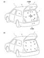
- First Embodiment 1A and 1B show a back door opening 3 in a state in which the back door 2 is flipped up in a general two-box type passenger vehicle 1.
- 1a is a vehicle roof
- 1b is a pillar portion at the rear of the vehicle.
- the peripheral edge of the back door opening 3 is trimmed by a combination of approximately four sides (4a, 4b, 4c) and approximately four corners (5a, 5c).
- the four side portions are a pair of left and right side portions extending in the vertical direction along the upper side portion 4a and the pillar portion 1b extending substantially horizontally along the upper edge (the rear end edge of the roof 1a) of the back door opening 3. 4b and a lower side portion 4c extending substantially horizontally along the lower edge of the back door opening 3.
- the four corner portions are a pair of left and right upper corner portions 5a positioned between the upper side portion 4a and the two side portions 4b, and left and right positions positioned between the lower side portion 4c and the two side portions 4b. It consists of a pair of lower corners 5c.
- FIG. 1A shows a state in which a weather strip 6 is attached to the peripheral edge of the back door opening 3.
- the weather strip 6 has an annular shape (or an endless string shape) so as to correspond to the peripheral edge of the back door opening 3, and the entire periphery of the peripheral edge of the back door opening 3 composed of the aforementioned side and corner portions. It is configured as a long rubber member having a length corresponding to the length.
- the weather strip 6 of the first embodiment includes at least a side corresponding part 6A as the first part, a corner corresponding part 6B, a lower side corresponding part 6C, and an upper side corresponding part 6D as the second part. Have.
- the weather strip 6 of the first embodiment has slightly different cross-sectional shape and size settings depending on the position along the longitudinal direction.
- inner circumference side and “outer circumference side” are used as terms for specifying the direction or orientation.
- outer peripheral side means the side facing the inner side (central area) of the peripheral edge of the back door opening 3 when the weather strip 6 is attached to the back door opening 3.
- outer peripheral side means the side facing the outer side of the peripheral edge of the back door opening 3 (the surrounding external environment).
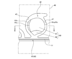
- FIG. 2 shows a cross section taken along the line II-II in FIG. 1, that is, a cross section of the side corresponding portion 6A of the weather strip 6 attached to the side portion 4b of the back door opening 3.
- the side corresponding portion 6A has an attachment portion 10 and a hollow tunnel-like seal portion 20A adjacent to and integrated with the attachment portion 10.
- the attachment portion 10 is a portion that is directly attached to a flange (not shown) as an attached body provided along the peripheral edge of the back door opening 3, It has a metal core 11 bent into a “U” shape (hereinafter referred to as “core 11”) and a rubber cover 12 attached to cover the core 11. And the four holding lip
- auxiliary lips (the vehicle inner lip 14a, A vehicle outer lip 14b and a front end lip 14c) are provided.
- the vehicle interior lip 14a is a cover lip for covering an end of an interior material such as a carpet or a cloth material.
- the vehicle outer lip 14 b and the front end lip 14 c are for sealing a gap that may be generated between the vehicle body and the mounting portion 10 when the weather strip 6 is mounted on the back door opening 3.
- a hollow tunnel-shaped seal portion 20 ⁇ / b> A is provided adjacent to the upper side of the attachment portion 10.
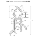
- This seal part 20A has an inner peripheral side wall part 21 and an outer peripheral side wall part 22, and is surrounded by these wall parts 21 and 22 so that the seal part 20A has a tunnel-shaped hollow with a substantially rhombic cross section. Area is reserved.
- the seal portion 20A has a line along one diagonal of the rhombus formed by the both wall portions 21 and 22 in a cross-sectional view (indicated by a horizontal alternate long and short dash line in FIG. 2) as a boundary line L for convenience. It can be divided into a side part and a cranial part.
- the “root side portion” refers to a portion adjacent to the attachment portion 10, and the “head side portion” refers to the remaining portion other than the root side portion.
- sticker part 20A is set as follows.
- the height of the seal portion 20A with reference to the top surface of the mounting portion 10 is set to h1.
- the height h1 is one index that represents the size of the outer shape of the seal portion in the cross section of the seal portion 20A.
- the rubber material forming the rubber covering portion 12 and the four holding lips 13 of the mounting portion 10 is formed by blending, for example, EPDM (ethylene propylene diene copolymer) with carbon black and a vulcanizing agent, Vulcanization with a vulcanizing agent (that is, polymer cross-linking reaction) is performed in the manufacturing process described later.
- EPDM ethylene propylene diene copolymer
- Vulcanization with a vulcanizing agent that is, polymer cross-linking reaction
- the rubber material forming the three auxiliary lips 14a to 14c and the seal portion 20A in the mounting portion 10 is formed by, for example, EPDM blended with carbon black, a vulcanizing agent, and a foaming agent.
- vulcanized with a vulcanizing agent that is, polymer crosslinking reaction
- foamed with a blowing agent foamed with a blowing agent (sponge).
- blowing agent that can be used here include 4,4′-oxybis (benzenesulfonylhydrazide) (OBSH) (for example, trade name: Neocerbon manufactured by Eiwa Kasei Kogyo Co., Ltd.), azodicarbonamide (ADCA), thermal expansion micro Capsule (for example, trade name: Advancel manufactured by Sekisui Chemical Co., Ltd.), physical foaming agent (for example, water, carbon dioxide) and the like can be exemplified.
- OBSH 4,4′-oxybis (benzenesulfonylhydrazide)
- ADCA azodicarbonamide
- thermal expansion micro Capsule for example, trade name: Advancel manufactured by Sekisui Chemical Co., Ltd.
- physical foaming agent for example, water, carbon dioxide
- the upper side corresponding part 6D and the lower side corresponding part 6C respectively attached to the upper side part 4a and the lower side part 4c of the back door opening 3 have the above-mentioned cross-sectional shape and dimensions. This is substantially the same as the side corresponding portion 6A.
- FIG. 3 shows a cross section taken along the line III-III in FIG. 1, that is, a cross section of the corner corresponding portion 6B of the weather strip 6 attached to the corner portion 5a of the back door opening 3.
- the corner corresponding portion 6B shown in this figure also has an attachment portion 10 and a hollow tunnel-like seal portion 20B.
- compatible part 6B is substantially the same as the attachment part 10 of 6 A of side corresponding parts in the shape and a dimension.
- the seal part 20B of the corner corresponding part 6B has an inner peripheral side wall part 21 and an outer peripheral side wall part 22, and is surrounded by these wall parts 21 and 22.
- a tunnel-shaped hollow region having a substantially rhombic cross section is secured in the seal portion 20B.
- This seal portion 20B has a line along one diagonal of the rhombus formed by both wall portions 21 and 22 in a cross-sectional view (indicated by a horizontal alternate long and short dash line in FIG. 3) as a boundary line L for convenience. It can be divided into a side part and a cranial part.
- sticker part 20B is set as follows.
- the height of the seal portion 20B with respect to the top surface of the mounting portion 10 is set to h2, and this height h2 represents the size of the outer shape of the seal portion in the cross section of the seal portion 20B.
- the wall thickness of each part in the wall parts 21 and 22 of the side corresponding part 6A and the wall thickness of each part in the wall parts 21 and 22 of the corner corresponding part 6B are set so as to satisfy the following relationship.
- Wall thickness at the base side portion of the inner peripheral side wall portion 21: t1R t3R
- Wall thickness at the base side portion of the outer peripheral side wall 22: t2R t4R That is, the wall thickness of the base side portion of the seal portion is substantially the same in the side corresponding portion 6A and the corner corresponding portion 6B.
- the base side portion of the seal portion 20A of the side corresponding portion 6A corresponds to the corner.
- the shape and size of the base portion of the seal portion 20B of the portion 6B are substantially the same, and there is no substantial difference between the two.
- the wall thickness of the head side portion of the seal portion the wall thickness (t3H, t4H) at the corner corresponding portion 6B exceeds the wall thickness (t1H, t2H) at the side corresponding portion 6A.
- the head portion of the corner corresponding portion 6B is generally thicker than the head portion of the side corresponding portion 6A.
- the height h2 of the seal part 20B in the corner corresponding part 6B is higher than the height h1 of the seal part 20A in the side corresponding part 6A (h1 ⁇ h2).
- the outer shape in the cross section of the seal portion 20B is larger than the outer shape in the cross section of the seal portion 20A.
- the side corresponding part 6A as the first part is arranged in the side part 4b of the back door opening 3, and the corner corresponding part 6B as the second part is the back door opening. It is arranged at the corner portion 5 a of the portion 3.
- the wall thickness of the base side portions of the seal portions 20A and B is substantially equal between the side corresponding portion 6A and the corner corresponding portion 6B, it is easy to easily follow the curved shape of the corner portion 5a. Can be bent.
- the wall thickness of the head portion of the seal portions 20A, B is thicker in the corner corresponding portion 6B than in the side corresponding portion 6A, and the rigidity of the seal portion 20B in the corner corresponding portion 6B is relatively high. It has become. For this reason, it is possible to prevent the seal portion 20B from being unnaturally crushed or causing wrinkles in the seal portion 20B when the corner corresponding portion 6B is bent.
- this embodiment also has the following advantages. That is, even when the weatherstrip 6 of this example is attached to the back door opening 3, the side corresponding part 6A is attached to the side part 4b that extends substantially straight, so that the seal part 20A undergoes some deformation action along with the attachment. The height of the seal portion 20A is maintained at h1 even after mounting. On the other hand, since the corner corresponding portion 6B is attached to the corner portion 5a having a locally large degree of curvature, the seal portion 20B is inevitably affected by the bending operation at the time of attachment. The influence appears as a deformation action in which the cross-sectional shape of the approximately rhombus is flattened in the height direction. Specifically, in FIG.
- the seal portion 20B is deformed such that the upper end portion 23 of the seal portion 20B descends (or sinks) toward the mounting portion 10, and as a result, the height of the seal portion 20B after mounting is increased.
- This is slightly lower than h2, which is the initial height.
- It is very difficult to set the initial height of the seal portion 20B to h2 (h1 + ⁇ h) by taking into account the descending amount (sinking amount) ⁇ h of the seal portion height caused by the curved deformation at the time of mounting. preferable.
- the height of the seal portion 20A corresponding to the side portion 4b and the seal portion 20B corresponding to the corner portion 5a are set. Both of the heights can be made substantially the same height (that is, h1), and as a result, the height of the seal portion after the mounting is achieved, and the sealing characteristics ( (Or seal quality) can be made constant over the entire circumference of the back door opening 3.
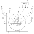
- FIG. 4 shows an outline of the production line 30 of the extrusion molding equipment.
- the production line 30 includes a cored bar supply uncoiler 31, an extrusion head 32, a heating tank 33, a cooler 34, a cored bar bending machine 35, and a take-up machine 36 arranged in series.
- a cored bar supply uncoiler 31 is a mechanism for unwinding and supplying the cored bar 11 for supplying the cored bar 11 straightened to the head 32 while rewinding a cored bar coil (not shown) formed by winding the strip-shaped cored bar 11. It is.
- the head 32 is an extrusion mold having a die 40 and a core 50 as mold elements, and supplies rubber materials for extrusion from the first, second, and third material extruders 37, 38, and 39. Receive. The head 32 will be described in detail later.
- the heating tank 33 is a long tunnel-shaped heating oven for vulcanization treatment and foaming treatment, and its total length ranges from several meters to several tens of meters.
- the heating method in the heating tank 33 may be, for example, hot air heating with combustion gas or the like, microwave heating, or both.
- the cooler 34 is a device for cooling the semi-finished product (intermediate product) after vulcanization and foaming treatment, and is typically constituted by a water tank filled with cooling water. The semi-finished product is cooled to an appropriate temperature by passing through this water tank.
- the cored bar bending machine 35 is a machining device for bending the semi-finished product after passing through the cooler 34 together with the cored bar to give the rubber product a final form as a weather strip.
- the take-up machine 36 is an apparatus for taking up a rubber product having a final form.
- the head 32 is connected to a total of three material extruders 37, 38 and 39.
- the first material extruder 37 supplies the rubber material for the rubber covering portion 12 and the holding lip 13, which is an EPDM rubber material containing a vulcanizing agent, to the head 32.
- the second material extruder 38 supplies the head 32 with a rubber material for the auxiliary lips 14a to 14c, which is an EPDM rubber material containing a vulcanizing agent and a foaming agent.
- the third material extruder 39 supplies the head 32 with the rubber material for the seal portions 20A and B, which is an EPDM rubber material containing a vulcanizing agent and a foaming agent.
- control device C is constituted by, for example, a factory automation (FA) computer or a programmable sequencer, and controls the head 32 and the material extruders 37 to 39 according to a predetermined control program or control sequence.
- FA factory automation
- the head 32 has a base 40 for extruding the outer shape of the weather strip 6 and a core 50 for mainly forming the inner wall portions of the hollow tunnel-shaped seal portions 20A and 20B.
- the base 40 supported by the frame (frame body) 32 b of the head 32 has a molding space (41, 42) for extrusion molding that is partitioned at a substantially central portion thereof. Yes.
- the lower half portion 41 of this molding space is a molding space (molding region) extending substantially horizontally for extruding the weather strip mounting portion 10, and a core extending straight in the lateral direction before being bent. It has a width that can accommodate and pass the gold 11.
- annular molding space means a cross-sectional shape of a closed meat part that forms a tunnel inside the meat part, and means an annular shape in a geometrically strict sense. Not what you want.
- FIG. 7 and 8 show schematic longitudinal cross sections of the base 40 and the core 50 at the YY line position in FIG.
- a core 11 in the central region of the base 40, there are a core 11 and a rubber material supply passage (main supply passage 43) extending along the extrusion direction (the direction from the left to the right of each drawing).
- the vicinity of the base outlet in the downstream area of the main supply passage 43 is positioned as the “mounting space 41 for the attachment portion”.
- an accommodation recess 44 is provided in the upper half region of the base 40, and a movable body 45 is held in the accommodation recess 44 so as to be capable of reciprocating back and forth along the extrusion direction.
- the movable body 45 is driven back and forth by a movable body drive mechanism 32a (see FIGS. 4 and 5).
- a part (lower part) of the movable body 45 plays a role as the movable core part 51.
- the core 50 that is located above the main supply passage 43 (and the mounting portion forming space 41) is a movable core 51 that is a part of the movable body 45. And a fixed core portion 52.
- the fixed core portion 52 is located immediately above the center position in the width direction of the main supply passage 43 (see FIGS. 5 and 6), and is a long portion (for example, a monorail-like portion) extending along the extrusion direction. It is formed (see FIGS. 7 and 8).
- the rear end portion of the fixed core portion 52 is connected to the main body portion of the base 40, and the fixed core portion 52 is integrated with the base 40.
- the fixed core portion 52 is located at the boundary between the molding space 41 for the weather strip mounting portion and the annular molding space 42 for the seal portion, and supports the movable body 45, and the movable body 45.
- a movable core portion 51 that is a part of the movable core portion 51 is supported so as to be movable back and forth along the extrusion direction.
- a supply passage (sub supply passage 46) of the rubber material for the seal portion extending in a substantially vertical direction is provided in the base 40 and in the vicinity of the housing recess 44.
- the lower end portion of the sub supply passage 46 communicates with the annular molding space 42 for the seal portion.
- the die 40 is formed with a molding facing surface 47 facing the outer peripheral surface (51a, 51b) of the movable core portion 51 at a predetermined interval in the vicinity of the outlet. .
- An annular molding space 42 for the seal portion is secured between the molding facing surface 47 and the cores (51, 52).
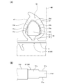
- the outer peripheral surface (51a, 51b) of the movable center part 51 is formed with a level
- the movable core portion 51 has a first outer peripheral surface 51a positioned closer to the tip, and a second outer peripheral surface 51b positioned rearward of the first outer peripheral surface 51a.
- the 2nd outer peripheral surface 51b is formed so that it may become a position higher than the 1st outer peripheral surface 51a.
- the first outer peripheral surface 51a corresponds to the small cross-sectional area portion of the movable core portion 51 having a relatively small cross-sectional area
- the second outer peripheral surface 51b has a cross-sectional area that is smaller than that of the small cross-sectional area portion.
- Corresponds to the large cross-sectional area of the movable core 51 which is relatively large. Therefore, as shown in FIG.
- the cross-sectional shape of the movable core 51 (and the entire core 50) arranged at the retracted position (second position) at the base outlet position is the forward position (first position).
- the movable core portion 51 (and the entire core 50) is configured to have a deformed cross section (a portion having a different cross-sectional shape) at at least two locations along the extrusion direction.
- the weather strip 6 of the first embodiment is manufactured through an extrusion process by the head 32, a vulcanization and foaming process, and a subsequent post-processing and post-processing process.
- the weather strip semi-finished product 6 ′ is appropriately switched between the forward position (first position) and the backward position (second position) of the movable core portion 51 which is a part of the movable body 45.
- Extrusion molding (see FIG. 9) is performed. That is, when the seal portion 20A of the side corresponding portion 6A as the first portion of the weather strip 6 is extruded, the movable body 45 and the movable core portion 51 are disposed at the forward movement position (FIG. 7) as the first position.
- the second outer peripheral surface 51 b of the movable core portion 51 is disposed to face the molding facing surface 47 of the base 40.
- the movable body 45 and the movable core portion 51 are disposed at the retracted position (FIG. 8) as the second position,
- the first outer peripheral surface 51 a of the movable core portion 51 is disposed to face the molding facing surface 47 of the base 40.
- the control device C changes the screw speed of the third material extruder 39 that supplies the seal portion rubber material to the head 32 according to the back-and-forth movement schedule of the movable core portion 51.
- the supply amount of the rubber material to the annular molding space 42 in the base 40 is adjusted.
- the screw rotation speed of the third material extruder 39 is increased. Is reduced (decelerated) to relatively reduce the supply amount per unit time of the rubber material for the seal portion.
- the screw rotational speed of the third material extruder 39 is increased. (Increase speed) to relatively increase the supply amount per unit time of the rubber material for the seal portion.
- the supply amount of the rubber material is constant (equal) in any part of the annular molding space 42 for the seal portion. Can be.
- a situation in which a part of the seal portion 20B of the corner corresponding portion 6B undulates can be avoided, and the entire surface of the seal portion 20B can be made smooth.
- the control device C synchronizes (completely matches) the switching timing of the position of the movable body 45 (and the movable core portion 51) and the switching timing of the screw rotation speed of the third material extruder 39.
- the screw rotation speed of the material extruder 39 is changed at a timing that precedes the switching timing of the movable core portion 51 by a predetermined time (D).
- This predetermined time (D) is the time lag from the change of the screw speed of the material extruder 39 until the change in the material supply amount according to the change of the screw speed actually appears in the annular molding space 42.
- the time lag is substantially eliminated by adopting a control method in which the screw rotation speed of the material extruder 39 for the seal portion is changed prior to the switching timing of the movable core portion 51.
- the weather strip semi-finished product 6 ′ immediately after being discharged from the head 32 is in a state in which the core metal 11 extends straight in the lateral direction.
- the hollow tunnel-like seal portions 20A and 20B in the semi-finished product 6 ′ are in a continuous state in the longitudinal direction, since the foaming agent in the rubber material is not foamed at this stage, the seal portion 20A There is still no significant difference between the height h1 and the height h2 of the seal portion 20B.
- the weather strip semi-finished product 6 ′ discharged from the head 32 is sent to the heating tank 33 and heated at a predetermined temperature (for example, 180 to 220 ° C.) for a predetermined time (for example, 1 to 9 minutes) before passing through the heating tank 33. Is done.
- a predetermined temperature for example, 180 to 220 ° C.
- a predetermined time for example, 1 to 9 minutes
- the vulcanizing agent contained in the rubber material is activated to vulcanize the rubber (polymer cross-linking reaction), and the foaming agent contained in the rubber material foams, and the seal portions 20A, B
- the expansion and sponging of the auxiliary lips 14a to 14c of the mounting portion 10 are achieved.
- seal part 20B expands with foaming of a foaming agent, reflecting the difference in the amount of foaming agents according to the wall thickness difference between the seal part 20A and the seal part 20B, a seal part
- the outer shape of the seal portion 20B is clearly larger than the outer shape of 20A. That is, the height h2 of the seal portion 20B is higher than the height h1 of the seal portion 20A (h1 ⁇ h2 after foaming).
- the weather strip semi-finished product 6 ′ subjected to the vulcanization and foaming treatment in the heating tank 33 is cooled by the cooler 34. Thereafter, the attachment portion 10 of the weather strip semi-finished product 6 ′ is bent into a U shape by a core metal bending machine 35, and the weather strip 6 (finished product) having a final cross-sectional shape as shown in the lower half of FIG. ).
- the weather strip 6 that has passed through the core bending machine 35 is taken up by the take-up machine 36, and quality-inspected and packed for shipment.
- the movable core 51 is disposed in the retracted position and the corner-corresponding portion 6B of the weather strip is extruded (FIG. 8).
- the cross-sectional area of the annular molding space 42 for the seal portion at the mouth outlet position is increased, and the rubber material for the seal portion into the molding space 42 is increased.
- the supply amount per unit time is increased.
- the supply amount per unit area of the rubber material for the seal portion can be made constant (equal) in any part of the molding space 42.
- the corner corresponding portion 6B It is possible to avoid a situation in which a part of the seal portion 20B is undulated.
- the core 50 that forms the annular molding space 42 in cooperation with the molding facing surface 47 of the base 40 includes the movable core portion 51 and the fixed core portion 52.
- the fixed core portion 52 functions as a support member for supporting the movable core portion 51 so as to be stably movable along the extrusion direction.
- the fixed core portion 52 also functions as a partition member (or partition material) for partitioning the main supply passage 43 for supplying the rubber material into the molding space 41 for the attachment portion in the base 40.
- the presence of the fixed core portion 52 prevents the rubber material for the seal portions 20A and B and the rubber material for the mounting portion 10 from being mixed randomly within the base 40, and the two types of rubber materials are ordered. It is possible to produce weatherstrips 6 distributed in some way.
- the lower side corresponding part 6C of the weather strip 6 has substantially the same cross-sectional shape and dimensions as the side corresponding part 6A and has a constant cross-sectional shape along the longitudinal direction.
- the portion excluding the central portion has the same cross-sectional shape and dimensions as the side corresponding portion 6A (first portion), and the lower portion corresponding portion 6C is replaced with the side corresponding portion 6A (first portion) as shown in FIG. )
- the corner corresponding portion 6B (second portion) may be configured as a “third portion of the weather strip” having a different cross-sectional shape and dimensions.
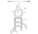
- FIG. 10 shows a cross section taken along the line XX of FIG. 1, that is, a cross section at the center of the lower side corresponding part 6C of the weather strip 6 attached to the lower side part 4c of the back door opening 3.
- the central part of the lower side corresponding part 6C shown in this figure also has an attachment part 10 and a hollow tunnel-like seal part 20C.
- compatible parts is as substantially the same as the attaching part 10 of 6 A of said side corresponding parts in a shape and a dimension.
- the seal portion 20C at the center of the lower side corresponding portion 6C has an inner peripheral side wall portion 21 and an outer peripheral side wall portion 22.
- a tunnel-shaped hollow region having a substantially hexagonal cross section is secured in the seal portion 20C by being surrounded by the wall portions 21 and 22.
- the wall thickness t5 of the inner peripheral side wall portion 21 and the wall thickness t6 of the outer peripheral side wall portion 22 are as follows. It is the largest.
- the long weather strip 6 having a central portion can be extruded by using a movable core portion 51 ′ obtained by slightly modifying the movable core portion 51 used in the first embodiment. is there.
- the movable core portion 51 ′ has a pair of left and right outer surfaces 51c erected substantially vertically on both the left and right sides of the most distal portion.
- the intermediate portion adjacent to the tip has a first outer peripheral surface 51a similar to that of the first embodiment, and further has a second outer peripheral surface 51b similar to that of the first embodiment at the rear thereof.
- a curved upper surface 51d (see FIG. 11B) connecting the upper end of the left outer surface 51c and the upper end of the right outer surface 51c at the most distal end of the movable core portion 51 ′ is a first outer periphery. It is continuous with the surface 51a and has substantially the same shape as the first outer peripheral surface 51a.
- the movable core portion 51 ′ is disposed at a first position where the second outer peripheral surface 51b is disposed opposite to the molding facing surface 47 of the die outlet.
- the part except a center part can be extrusion-molded among 6 A of side side corresponding parts and 6 C of lower side corresponding
- compatible part 6B as a 2nd part is extrusion-molded by arrange
- die exit. can do.
- the movable core portion 51 ′ is arranged at a third position where the two outer side surfaces 51 c and the upper surface 51 d are arranged opposite to the molding facing surface 47 of the mouthpiece outlet, so that the lower side corresponding part 6 C as the third part.
- the central part of the film can be extruded.
- the weather strip 6 having the thickest seal portion 20C at the center of the lower side corresponding portion 6C is very preferable to use the weather strip 6 having the thickest seal portion 20C at the center of the lower side corresponding portion 6C as the weather strip for the back door opening 3.
- a device for detecting the half-door state of the back door 2 is often provided along with the locking mechanism of the back door 2 near the center of the lower side 4c.
- positioned around this half-door state detection apparatus is weak, the said detection apparatus will be in "half-door state" although the back door 2 is closed completely. “Some” may be erroneously detected and the half-door warning light may be erroneously turned on.
- the resilience resilience of the seal portion of the weatherstrip disposed around the half-door state detection device is high to some extent. Therefore, it is said that increasing the repulsive force of the seal portion 20C by relatively increasing the wall thickness of the seal portion 20C corresponding to the central portion of the lower side portion 4c helps to prevent erroneous lighting of the half-door warning lamp.
- rubber stoppers may be provided at predetermined locations on the vehicle door.
- the weather strip seal portion to be mounted around the periphery of the door or the door opening may be shaped like a seal portion 20C in FIG. The reason for this is that repeated opening and closing of the door may cause the stopper to crack and break, and in order to prevent such damage to the stopper, the weather strip attached around the area where the stopper hits This is because it is preferable to increase the impact resilience of the seal portion so as to reduce the impact applied to the stopper when the door is closed. Therefore, it is possible to prevent breakage of the stopper by increasing the repulsive force of the seal portion by relatively increasing the wall thickness as in the seal portion 20C of FIG.
- the shape for increasing the resilience of the seal portion is not limited to the shape of the seal portion 20C in FIG. 10, and for example, as shown in FIG. 12, the inner surface near the top of the seal portion 20C (that is, near the upper end 23).
- the shape which formed the semicircle-shaped thick part 24 in the side may be sufficient.
- FIG. 13 (A) is a view corresponding to FIG. 1 (A) of the first embodiment
- FIG. 13 (B) is the same view as FIG. 1 (B).
- the weather strip 6 of the second embodiment has at least a side corresponding part 6E, a lower side corresponding part 6F as a first part, and an upper side corresponding part 6G as a second part. ing.
- FIG. 14 shows a cross section taken along the line PP in FIG. 13A, that is, a cross section of the lower side corresponding part 6F of the weather strip 6 attached to the lower side part 4c of the back door opening 3.
- FIG. 15 shows a cross section taken along the line QQ of FIG. 13A, that is, a cross section of the upper side corresponding part 6G of the weather strip 6 attached to the upper side part 4a of the back door opening 3.
- the lower side corresponding part 6F (or the upper side corresponding part 6G) includes a mounting part 10 and a hollow tunnel-like seal part 20F (or seal part 20G) adjacent to and integrated with the mounting part 10. ).
- the mounting portion 10 of the lower side corresponding portion 6F and the mounting portion 10 of the upper side corresponding portion 6G are not only substantially the same in shape and size, but also the core as in the mounting portion 10 (see FIGS. 2 and 3) of the first embodiment. It has a gold 11, a rubber covering portion 12, four holding lips 13, and three auxiliary lips (a vehicle inner lip 14a, a vehicle outer lip 14b, and a front end lip 14c).
- the seal part 20F of the lower side corresponding part 6F and the seal part 20G of the upper side corresponding part 6G both have an inner peripheral side wall part 21 and an outer peripheral side wall part 22, and are crossed by being surrounded by these wall parts 21 and 22. This is common in that a substantially circular tunnel-shaped hollow region is secured.
- the seal portion 20G is generally thicker than the seal portion 20F, and the wall thickness t8 of the seal portion 20G is thicker than the wall thickness t7 of the seal portion 20F at the corresponding wall thickness measurement points. (T7 ⁇ t8).
- the side corresponding portion 6E attached to the side portion 4b of the back door opening 3 has the above-mentioned lower side corresponding portion 6F (first side) in both the cross-sectional shape and dimensions. Part).
- the weather strip 6 according to the second embodiment shown in FIGS. 13 to 15 can be extruded using an extrusion equipment as shown in FIGS.
- the extrusion molding equipment of the second embodiment has the same basic configuration as the extrusion molding equipment of the first embodiment (FIGS. 4 to 8), but the structure of the core (particularly the movable core) and the material extrusion The number and arrangement of the machines are different from the first embodiment. Hereinafter, differences from the first embodiment will be mainly described.
- the core 60 of the second embodiment includes a movable core portion 61 and a fixed core portion 62.
- the fixed core portion 62 of the second embodiment has a slightly different frontal shape from the fixed core portion 52 of the first embodiment, but the basic function and role are substantially the same as those of the fixed core portion 52 of the first embodiment. Are the same.
- the movable core portion 61 of the second embodiment is configured by a part (lower portion) of the movable body 45 and extends along the extrusion direction, as in the first embodiment.
- the movable core portion 61 is configured to have a deformed cross section at the tip portion (downstream portion in the extrusion direction) and the tip trailing portion following the tip portion (upstream side).
- the outer peripheral surface 61 a of the distal end portion of the movable core portion 61 and the outer peripheral surface 61 b of the distal end portion of the movable core portion 61 are the front surface of the movable core portion 61.
- the outer peripheral surface 61a of the distal end portion of the movable core portion 61 corresponds to the small sectional area portion of the movable core portion 61 having a relatively small cross-sectional area
- the outer peripheral surface 61b of the distal end trailing portion has a cross-sectional area. This corresponds to a large cross-sectional area portion of the movable core portion 61 that is relatively larger than the small cross-sectional area portion.
- the movable core portion 61 (and the movable body 45) is disposed at the forward movement position (first position), and the outer peripheral surface 61b of the distal end portion of the movable core portion 61 is connected to the base.
- the widths of the upper side, the right side, and the left side of the annular molding space 42 for the seal portion are all relatively narrow.
- the movable core portion 61 (and the movable body 45) is disposed at the retracted position (second position), and the outer peripheral surface 61a of the distal end portion of the movable core portion 61 is connected to the base outlet.
- the widths of the upper and right sides of the annular molding space 42 for the seal portion remain substantially the same as in the case of FIG.
- the width on the left side of the molding space 42 is relatively wider than in the case of FIG.
- the cross-sectional shape of the movable core portion 61 (and the entire core 60) disposed at the retracted position (second position) at the base outlet position is the forward position (first position). From the cross-sectional shape of the movable core 61 (and the entire core 60) disposed at the position 1 at the base outlet position, the left side of the left and right direction (width direction) is cut out. (See FIG. 17). As described above, the movable core portion 61 (and the entire core 60) is configured to have irregular cross sections (locations having different cross-sectional shapes) at least at two locations along the extrusion direction.
- the extrusion equipment of the second embodiment includes a total of four material extruders 37, 38, 391 and 392.
- the first material extruder 37 is for supplying the rubber material for the rubber covering portion 12 and the holding lip 13, which is an EPDM rubber material containing a vulcanizing agent, to the head 32.
- the second material extruder 38 is for supplying the head 32 with a rubber material for the auxiliary lips 14a to 14c, which is an EPDM rubber material containing a vulcanizing agent and a foaming agent.
- the third and fourth material extruders 391 and 392 in the second embodiment are the third material extruder 39 in the first embodiment (a EPDM rubber material containing a vulcanizing agent and a foaming agent).
- the third material extruder 391 seals a portion for molding the outer peripheral side wall portion 22 in the annular molding space 42 for the seal portion (a substantially half-circumferential portion on the right side of the annular molding space 42 shown in FIG. 16). It is the material extruder for seal part outer peripheral sides for supplying the rubber material for parts.
- the fourth material extruder 392 is a portion for molding the inner peripheral side wall portion 21 in the annular molding space 42 for the seal portion (the substantially half-left portion of the annular molding space 42 shown in FIG. 16). ) Is a seal portion inner peripheral side material extruder for supplying the seal portion rubber material.
- These four material extruders 37, 38, 391 and 392, and the head 32 are electrically connected to the control device C and controlled by the control device C.
- the arrangement of the movable core portion 61 that is a part of the movable body 45 is set to the forward position (first position) and the backward position (second position).
- the weatherstrip semi-finished product is extruded while appropriately switching between the two.
- the movable core portion 61 is disposed at the forward position as the first position (see FIG. 18A).
- the outer peripheral surface 61b of the rear end portion of the movable core portion 61 is disposed opposite to the molding facing surface 47 of the base 40.
- the movable core portion 61 is disposed at the retracted position as the second position (see FIG. 18B) and is movable.
- the outer peripheral surface 61 a at the tip of the middle core portion 61 is disposed to face the molding facing surface 47 of the base 40.
- the left side (inner peripheral side) is wider than the right side (outer peripheral side) of the sealing portion molding space 42 at the base outlet position.
- the control device C changes the screw rotation speed of the fourth material extruder 392 (material extruder for the inner peripheral side of the seal portion) according to the back-and-forth movement schedule of the movable core portion 61, The supply amount of the rubber material to the left side (inner peripheral side) of the annular molding space 42 is adjusted. Specifically, when the extrusion process is in the extrusion stage of the first portion 6F (that is, the seal portion 20F) (see FIG. 18A), the screw speed of the fourth material extruder 392 is reduced. (Deceleration) to relatively reduce the supply amount per unit time of the rubber material for the seal portion.
- the supply amount per unit area of the rubber material for the seal portion can be made constant (equal).
Landscapes
- Engineering & Computer Science (AREA)
- Mechanical Engineering (AREA)
- Manufacturing & Machinery (AREA)
- Seal Device For Vehicle (AREA)
- Extrusion Moulding Of Plastics Or The Like (AREA)
Abstract
L'invention concerne un long joint d'étanchéité dans lequel l'épaisseur de paroi d'une partie d'étanchéité creuse est partiellement modifiée. L'invention concerne également un procédé de fabrication du joint d'étanchéité sur la base d'un procédé de moulage par extrusion. Un moule de moulage par extrusion comprend une matrice (40) et un noyau (50). Le noyau (50) comporte une partie de noyau mobile (51) qui peut se déplacer dans la direction d'extrusion et une partie de noyau fixe (52). La forme latérale en coupe transversale de la partie de noyau mobile (51) n'est pas la même en deux emplacements (51a, 51b) vers l'avant et vers l'arrière dans la direction d'extrusion. Une première partie (6A) du long joint d'étanchéité comprend la partie de noyau mobile (51) disposée en une position avancée (première position). Une seconde partie (6B) du long joint d'étanchéité comprend la partie de noyau mobile (51) disposée en une position rétractée (seconde position). Pendant le moulage de la seconde partie (6B), la quantité de matériau de partie d'étanchéité délivré par unité de temps dans un espace de moulage (42) destiné à la partie d'étanchéité creuse fixée entre le noyau et la matrice est augmentée par rapport au moulage de la première partie (6A).
Priority Applications (3)
| Application Number | Priority Date | Filing Date | Title |
|---|---|---|---|
| CN201680084007.3A CN108883690B (zh) | 2016-03-28 | 2016-09-01 | 挡风雨条及其制造方法 |
| US16/088,256 US10751925B2 (en) | 2016-03-28 | 2016-09-01 | Weather strip and method for manufacturing same |
| KR1020187027783A KR102290598B1 (ko) | 2016-03-28 | 2016-09-01 | 웨더 스트립 및 그 제조 방법 |
Applications Claiming Priority (2)
| Application Number | Priority Date | Filing Date | Title |
|---|---|---|---|
| JP2016-063075 | 2016-03-28 | ||
| JP2016063075A JP6653607B2 (ja) | 2016-03-28 | 2016-03-28 | ウェザーストリップの製造方法 |
Publications (1)
| Publication Number | Publication Date |
|---|---|
| WO2017168782A1 true WO2017168782A1 (fr) | 2017-10-05 |
Family
ID=59963923
Family Applications (1)
| Application Number | Title | Priority Date | Filing Date |
|---|---|---|---|
| PCT/JP2016/075647 Ceased WO2017168782A1 (fr) | 2016-03-28 | 2016-09-01 | Joint d'étanchéité et son procédé de fabrication |
Country Status (5)
| Country | Link |
|---|---|
| US (1) | US10751925B2 (fr) |
| JP (1) | JP6653607B2 (fr) |
| KR (1) | KR102290598B1 (fr) |
| CN (1) | CN108883690B (fr) |
| WO (1) | WO2017168782A1 (fr) |
Cited By (1)
| Publication number | Priority date | Publication date | Assignee | Title |
|---|---|---|---|---|
| CN112537186A (zh) * | 2020-11-27 | 2021-03-23 | 哈尔滨北方防务装备股份有限公司 | 一种双节履带车水密舱门系统 |
Families Citing this family (10)
| Publication number | Priority date | Publication date | Assignee | Title |
|---|---|---|---|---|
| US9313927B2 (en) | 2010-11-08 | 2016-04-12 | Chatsworth Products, Inc. | Header panel assembly for preventing air circulation above electronic equipment enclosure |
| US9955616B2 (en) | 2010-11-08 | 2018-04-24 | Chatsworth Products, Inc. | Header panel assembly for preventing air circulation above electronic equipment enclosure |
| US20140196394A1 (en) * | 2013-01-11 | 2014-07-17 | Chatsworth Products, Inc. | Modular thermal isolation barrier for data processing equipment structure |
| JP6437426B2 (ja) * | 2015-12-22 | 2018-12-12 | 東海興業株式会社 | シール材及びその取付構造 |
| JP6653607B2 (ja) * | 2016-03-28 | 2020-02-26 | 東海興業株式会社 | ウェザーストリップの製造方法 |
| JP6858740B2 (ja) * | 2018-11-29 | 2021-04-14 | 西川ゴム工業株式会社 | ウェザーストリップ、ウェザーストリップの取付構造、およびウェザーストリップの取付方法 |
| JP7475197B2 (ja) | 2020-05-15 | 2024-04-26 | 東海興業株式会社 | ウェザーストリップ用の接合シート材、ウェザーストリップ及びその製造方法 |
| CN114198006B (zh) * | 2021-12-06 | 2024-02-06 | 北京卫星制造厂有限公司 | 一种曲面密封结构的安装调试方法 |
| US20230302885A1 (en) * | 2022-02-17 | 2023-09-28 | Cooper-Standard Automotive Inc. | Sealing lip having improved load loss and compression set properties |
| CN118082150B (zh) * | 2024-04-23 | 2024-08-20 | 兴化市纪宇塑业有限公司 | 一种塑料密封条挤出成型机 |
Citations (4)
| Publication number | Priority date | Publication date | Assignee | Title |
|---|---|---|---|---|
| JPS63132022A (ja) * | 1986-11-21 | 1988-06-04 | Nishikawa Rubber Kogyo Kk | 自動車ウエザ−ストリツプの製造法及び同装置 |
| JPH031857U (fr) * | 1989-05-29 | 1991-01-10 | ||
| JPH11179782A (ja) * | 1997-12-22 | 1999-07-06 | Nishikawa Rubber Co Ltd | ドアウェザーストリップの製造装置及びドアウェザーストリップの製造方法 |
| JP2007290586A (ja) * | 2006-04-26 | 2007-11-08 | Nishikawa Rubber Co Ltd | オープニングシールおよび同製造方法 |
Family Cites Families (22)
| Publication number | Priority date | Publication date | Assignee | Title |
|---|---|---|---|---|
| JPS5676542U (fr) * | 1979-11-20 | 1981-06-22 | ||
| JPS6422651A (en) * | 1987-07-20 | 1989-01-25 | Kinugawa Rubber Ind | Weather strip for automobile |
| JPH01154948U (fr) * | 1988-04-09 | 1989-10-25 | ||
| JP2756480B2 (ja) * | 1989-11-22 | 1998-05-25 | 東海興業株式会社 | ウェザーストリップの成形方法、及びその装置 |
| JPH0531784A (ja) * | 1991-07-30 | 1993-02-09 | Toyo Tire & Rubber Co Ltd | 自動車用ウエザストリツプ及びその成形方法 |
| JP3407179B2 (ja) * | 1996-06-18 | 2003-05-19 | 三菱自動車エンジニアリング株式会社 | ドア構造 |
| JP2008007031A (ja) * | 2006-06-30 | 2008-01-17 | Tokai Kogyo Co Ltd | ウエザーストリップ |
| JP4521677B2 (ja) * | 2007-04-02 | 2010-08-11 | トキワケミカル工業株式会社 | 自動車用ウェザーストリップ |
| DE102008010547B3 (de) * | 2008-02-22 | 2009-08-20 | Metzeler Automotive Profile Systems Gmbh | Abdeckleiste für Kraftfahrzeuge |
| JP4797125B2 (ja) * | 2008-06-20 | 2011-10-19 | トキワケミカル工業株式会社 | 芯材を有する押出し成形品 |
| JP5513750B2 (ja) * | 2009-02-03 | 2014-06-04 | 東海興業株式会社 | ウェザーストリップ及びウェザーストリップの取付構造 |
| JP5563316B2 (ja) * | 2009-03-18 | 2014-07-30 | 東海興業株式会社 | 芯材の製造方法及びトリム材の製造方法並びに芯材 |
| US20120240473A1 (en) * | 2011-03-23 | 2012-09-27 | Toyoda Gosei Co., Ltd. | Weather strip and production method thereof |
| JP6168828B2 (ja) * | 2013-04-17 | 2017-07-26 | 鬼怒川ゴム工業株式会社 | 自動車のウエザーストリップ |
| CN204172667U (zh) * | 2014-09-29 | 2015-02-25 | 上汽通用五菱汽车股份有限公司 | 蝶形窗密封胶条结构 |
| JP6228166B2 (ja) * | 2015-07-03 | 2017-11-08 | 西川ゴム工業株式会社 | 自動車用ウェザーストリップ |
| JP2017024432A (ja) * | 2015-07-15 | 2017-02-02 | アイシン精機株式会社 | サンルーフ装置のウエザストリップ |
| JP6437426B2 (ja) * | 2015-12-22 | 2018-12-12 | 東海興業株式会社 | シール材及びその取付構造 |
| JP6434398B2 (ja) * | 2015-12-22 | 2018-12-05 | 東海興業株式会社 | 自動車用ウェザーストリップ |
| JP6508073B2 (ja) * | 2016-01-27 | 2019-05-08 | 株式会社豊田自動織機 | ウエザストリップ |
| JP6694721B2 (ja) * | 2016-02-10 | 2020-05-20 | 西川ゴム工業株式会社 | ウェザーストリップ |
| JP6653607B2 (ja) * | 2016-03-28 | 2020-02-26 | 東海興業株式会社 | ウェザーストリップの製造方法 |
-
2016
- 2016-03-28 JP JP2016063075A patent/JP6653607B2/ja active Active
- 2016-09-01 KR KR1020187027783A patent/KR102290598B1/ko active Active
- 2016-09-01 CN CN201680084007.3A patent/CN108883690B/zh active Active
- 2016-09-01 WO PCT/JP2016/075647 patent/WO2017168782A1/fr not_active Ceased
- 2016-09-01 US US16/088,256 patent/US10751925B2/en active Active
Patent Citations (4)
| Publication number | Priority date | Publication date | Assignee | Title |
|---|---|---|---|---|
| JPS63132022A (ja) * | 1986-11-21 | 1988-06-04 | Nishikawa Rubber Kogyo Kk | 自動車ウエザ−ストリツプの製造法及び同装置 |
| JPH031857U (fr) * | 1989-05-29 | 1991-01-10 | ||
| JPH11179782A (ja) * | 1997-12-22 | 1999-07-06 | Nishikawa Rubber Co Ltd | ドアウェザーストリップの製造装置及びドアウェザーストリップの製造方法 |
| JP2007290586A (ja) * | 2006-04-26 | 2007-11-08 | Nishikawa Rubber Co Ltd | オープニングシールおよび同製造方法 |
Cited By (2)
| Publication number | Priority date | Publication date | Assignee | Title |
|---|---|---|---|---|
| CN112537186A (zh) * | 2020-11-27 | 2021-03-23 | 哈尔滨北方防务装备股份有限公司 | 一种双节履带车水密舱门系统 |
| CN112537186B (zh) * | 2020-11-27 | 2023-03-31 | 哈尔滨北方防务装备股份有限公司 | 一种双节履带车水密舱门系统 |
Also Published As
| Publication number | Publication date |
|---|---|
| US20190084209A1 (en) | 2019-03-21 |
| JP2017177828A (ja) | 2017-10-05 |
| KR102290598B1 (ko) | 2021-08-17 |
| JP6653607B2 (ja) | 2020-02-26 |
| KR20180129790A (ko) | 2018-12-05 |
| US10751925B2 (en) | 2020-08-25 |
| CN108883690A (zh) | 2018-11-23 |
| CN108883690B (zh) | 2021-12-21 |
Similar Documents
| Publication | Publication Date | Title |
|---|---|---|
| WO2017168782A1 (fr) | Joint d'étanchéité et son procédé de fabrication | |
| US5523041A (en) | Windshield molding for vehicles and the production method thereof | |
| US3825459A (en) | Method of making flexible molding strip | |
| JP2008184092A (ja) | ドアウエザストリップ及びその製造方法 | |
| JP6650749B2 (ja) | ウェザーストリップの製造方法 | |
| JP6903115B2 (ja) | ウェザーストリップ | |
| JP4282168B2 (ja) | 自動車計器パネル用外装体の製造方法 | |
| JP2008044573A (ja) | ウエザストリップ及びその製造方法 | |
| US20110291437A1 (en) | Vehicle window molding and method for molding the same | |
| JP4846430B2 (ja) | オープニングシールおよび同製造方法 | |
| JP2008044572A (ja) | ドアウエザストリップ及びその製造方法 | |
| JP2007296669A (ja) | 自動車用シール部材の製造方法 | |
| KR100471020B1 (ko) | 열가소성 고무를 이용한 웨더스트립의 제조방법 및 그 구금장치 | |
| GB2333796A (en) | Sealing strip having soft extruded material covering support member and fixing means | |
| JP2003181902A (ja) | 長尺シール材の製造方法 | |
| JP4003607B2 (ja) | 自動車用ウエザストリップの製造方法 | |
| JPH07237442A (ja) | 車両用ウインドモール | |
| JP2010253721A (ja) | 射出成形用金型及び成形体 | |
| JP2003191749A (ja) | 車両内装部材およびその製造方法 | |
| JPH05177690A (ja) | 自動車用ウインドモールディングの製造装置及び製造方法 | |
| JP4164813B2 (ja) | 長尺成形品の製造方法 | |
| JP4304663B2 (ja) | 表皮一体発泡成形品の製造方法 | |
| JP4664137B2 (ja) | 自動車用ウェザーストリップの製造方法 | |
| JP2006044286A (ja) | ウェザーストリップおよびウェザーストリップあるいは詰物の製造方法 | |
| JPH07148819A (ja) | 中空断面部を備えた長尺ゴム製品の製造方法 |
Legal Events
| Date | Code | Title | Description |
|---|---|---|---|
| ENP | Entry into the national phase |
Ref document number: 20187027783 Country of ref document: KR Kind code of ref document: A |
|
| NENP | Non-entry into the national phase |
Ref country code: DE |
|
| 121 | Ep: the epo has been informed by wipo that ep was designated in this application |
Ref document number: 16896999 Country of ref document: EP Kind code of ref document: A1 |
|
| 122 | Ep: pct application non-entry in european phase |
Ref document number: 16896999 Country of ref document: EP Kind code of ref document: A1 |