WO2017168802A1 - 操船装置 - Google Patents
操船装置 Download PDFInfo
- Publication number
- WO2017168802A1 WO2017168802A1 PCT/JP2016/080442 JP2016080442W WO2017168802A1 WO 2017168802 A1 WO2017168802 A1 WO 2017168802A1 JP 2016080442 W JP2016080442 W JP 2016080442W WO 2017168802 A1 WO2017168802 A1 WO 2017168802A1
- Authority
- WO
- WIPO (PCT)
- Prior art keywords
- propeller
- backward
- thrust
- starboard
- ship
- Prior art date
- Legal status (The legal status is an assumption and is not a legal conclusion. Google has not performed a legal analysis and makes no representation as to the accuracy of the status listed.)
- Ceased
Links
Images


Classifications
-
- B—PERFORMING OPERATIONS; TRANSPORTING
- B63—SHIPS OR OTHER WATERBORNE VESSELS; RELATED EQUIPMENT
- B63H—MARINE PROPULSION OR STEERING
- B63H25/00—Steering; Slowing-down otherwise than by use of propulsive elements; Dynamic anchoring, i.e. positioning vessels by means of main or auxiliary propulsive elements
- B63H25/42—Steering or dynamic anchoring by propulsive elements; Steering or dynamic anchoring by propellers used therefor only; Steering or dynamic anchoring by rudders carrying propellers
-
- B—PERFORMING OPERATIONS; TRANSPORTING
- B63—SHIPS OR OTHER WATERBORNE VESSELS; RELATED EQUIPMENT
- B63H—MARINE PROPULSION OR STEERING
- B63H21/00—Use of propulsion power plant or units on vessels
- B63H21/21—Control means for engine or transmission, specially adapted for use on marine vessels
-
- B—PERFORMING OPERATIONS; TRANSPORTING
- B63—SHIPS OR OTHER WATERBORNE VESSELS; RELATED EQUIPMENT
- B63H—MARINE PROPULSION OR STEERING
- B63H25/00—Steering; Slowing-down otherwise than by use of propulsive elements; Dynamic anchoring, i.e. positioning vessels by means of main or auxiliary propulsive elements
- B63H25/02—Initiating means for steering, for slowing down, otherwise than by use of propulsive elements, or for dynamic anchoring
-
- B—PERFORMING OPERATIONS; TRANSPORTING
- B63—SHIPS OR OTHER WATERBORNE VESSELS; RELATED EQUIPMENT
- B63H—MARINE PROPULSION OR STEERING
- B63H25/00—Steering; Slowing-down otherwise than by use of propulsive elements; Dynamic anchoring, i.e. positioning vessels by means of main or auxiliary propulsive elements
- B63H25/06—Steering by rudders
- B63H25/08—Steering gear
- B63H25/14—Steering gear power assisted; power driven, i.e. using steering engine
- B63H25/18—Transmitting of movement of initiating means to steering engine
- B63H25/24—Transmitting of movement of initiating means to steering engine by electrical means
-
- B—PERFORMING OPERATIONS; TRANSPORTING
- B63—SHIPS OR OTHER WATERBORNE VESSELS; RELATED EQUIPMENT
- B63H—MARINE PROPULSION OR STEERING
- B63H5/00—Arrangements on vessels of propulsion elements directly acting on water
- B63H5/07—Arrangements on vessels of propulsion elements directly acting on water of propellers
- B63H5/08—Arrangements on vessels of propulsion elements directly acting on water of propellers of more than one propeller
-
- B—PERFORMING OPERATIONS; TRANSPORTING
- B63—SHIPS OR OTHER WATERBORNE VESSELS; RELATED EQUIPMENT
- B63H—MARINE PROPULSION OR STEERING
- B63H5/00—Arrangements on vessels of propulsion elements directly acting on water
- B63H5/07—Arrangements on vessels of propulsion elements directly acting on water of propellers
- B63H5/16—Arrangements on vessels of propulsion elements directly acting on water of propellers characterised by being mounted in recesses; with stationary water-guiding elements; Means to prevent fouling of the propeller, e.g. guards, cages or screens
-
- B—PERFORMING OPERATIONS; TRANSPORTING
- B63—SHIPS OR OTHER WATERBORNE VESSELS; RELATED EQUIPMENT
- B63H—MARINE PROPULSION OR STEERING
- B63H21/00—Use of propulsion power plant or units on vessels
- B63H21/21—Control means for engine or transmission, specially adapted for use on marine vessels
- B63H2021/216—Control means for engine or transmission, specially adapted for use on marine vessels using electric control means
-
- B—PERFORMING OPERATIONS; TRANSPORTING
- B63—SHIPS OR OTHER WATERBORNE VESSELS; RELATED EQUIPMENT
- B63H—MARINE PROPULSION OR STEERING
- B63H25/00—Steering; Slowing-down otherwise than by use of propulsive elements; Dynamic anchoring, i.e. positioning vessels by means of main or auxiliary propulsive elements
- B63H25/02—Initiating means for steering, for slowing down, otherwise than by use of propulsive elements, or for dynamic anchoring
- B63H2025/026—Initiating means for steering, for slowing down, otherwise than by use of propulsive elements, or for dynamic anchoring using multi-axis control levers, or the like, e.g. joysticks, wherein at least one degree of freedom is employed for steering, slowing down, or dynamic anchoring
-
- B—PERFORMING OPERATIONS; TRANSPORTING
- B63—SHIPS OR OTHER WATERBORNE VESSELS; RELATED EQUIPMENT
- B63H—MARINE PROPULSION OR STEERING
- B63H21/00—Use of propulsion power plant or units on vessels
- B63H21/21—Control means for engine or transmission, specially adapted for use on marine vessels
- B63H21/213—Levers or the like for controlling the engine or the transmission, e.g. single hand control levers
Definitions
- the present invention relates to a boat maneuvering device mounted on a ship.
- a ship that transmits power from a prime mover (engine) arranged inside a hull to a forward / reverse propeller arranged outside the hull via a switching clutch and a propeller shaft is known.
- a ship provided with a side thruster for laterally moving the ship toward the left and right sides in order to improve the maneuverability at the time of berthing or the like.
- a propeller is arranged near the center in the left-right direction on the bow side so that thrust is generated in the left-right direction.
- a marine vessel maneuvering apparatus capable of simplifying the maneuvering of the ship by using a joystick lever is known (see Patent Document 1).
- the desired joystick movement such as parallel movement of the hull, turning on the spot, etc.
- the joystick lever can be easily realized by operating the joystick lever as the maneuvering means, even if the operator does not know the change in hull behavior. can do.
- the turning center defined in calculating the rotational moment acting on the hull does not necessarily coincide with the turning center intended by the onboard operator. Further, when the pilots on board are different, the turning center intended by each pilot is different for each pilot, and there is a possibility that the operational feeling of the pilot is impaired.
- each pilot can appropriately carry out calibration for turning (turning calibration) as necessary so that the turning around the turning center intended by each pilot can be obtained each time, Decrease in operation feeling can be prevented. Therefore, a boat maneuvering device that can easily carry out the calibration for turning is desired so that a desired turning can be obtained for each pilot who gets on board.
- the present invention aims to provide a ship maneuvering device that can easily carry out calibration for turning.
- a marine vessel maneuvering device is provided on a ship provided with a port propeller propeller that is connected to a port propeller shaft and generates thrust, and a starboard propeller that is connected to a starboard propeller shaft and generates thrust.
- a marine vessel maneuvering device that is configured to be freely rotatable and tiltable, and includes a joystick lever for determining a moving speed and a moving direction of the ship, and the rotation of the joystick lever at the time of turning calibration
- the port forward / backward propeller and the starboard forward / backward propeller are rotated by operation, and the joystick lever is tilted to move the port forward / backward propeller forward / backward propulsion ratio or the starboard forward / backward propeller propeller ratio.
- the thrust generated according to the changed forward / rearward propulsion ratio is set as a correction coefficient, or the changed forward / backward propeller and Among the thrusts generated by the rotational speeds of the starboard forward and backward propellers, by setting the thrust of the left and right propeller propellers by the tilt operation and the thrust of the starboard forward and backward propellers as correction coefficients, Calibration is performed.
- a marine vessel maneuvering device is provided on a ship provided with a port propeller propeller that is connected to a port propeller shaft and generates thrust, and a starboard propeller that is connected to a starboard propeller shaft and generates thrust.
- a marine vessel maneuvering apparatus comprising: a joystick lever configured to be rotatable and configured to determine a turning speed and a turning direction of the ship; and an operating means for moving the ship forward or backward.
- the port forward / backward propeller and the starboard forward / backward propeller are rotated by rotating the joystick lever, respectively, and the forward / backward propulsion ratio of the port forward / backward propeller by the predetermined operation of the operating means or The forward / backward propulsion ratio of the starboard forward / backward propeller, or the port forward / backward propeller and the starboard forward / backward travel
- the thrust generated according to the changed forward / reverse propulsion ratio is set as a correction coefficient or the changed Out of the thrusts generated by the rotational speeds of the port-side forward and backward propellers and the starboard forward-and-back propellers, the thrust of the port forward and backward propellers and the thrust of the starboard forward and backward propellers by the predetermined operation are set as correction coefficients.
- the rotational speeds of the port and starboard forward and backward propellers under the situation where the turning intended by the operator is realized by the combination of the rotation operation and the tilt operation of the joystick lever are rotated. It can be easily determined as the number of rotations to be generated when operated. As described above, the turning calibration can be easily performed for each pilot who is on board by combining the rotation operation and the tilt operation of the joystick lever. Therefore, it is possible to provide a boat maneuvering device that can easily carry out the turning calibration.
- the turning calibration can be easily performed for each pilot who gets on board by combining the rotation operation of the joystick lever and the predetermined operation of the operation means. Therefore, it is possible to provide a boat maneuvering device that can easily carry out the turning calibration.
- FIG. 1 Schematic which shows the whole outline
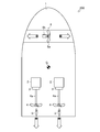
- the schematic plan view which shows arrangement
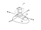
- the perspective view which shows the structure of the joystick lever of a boat maneuvering apparatus.
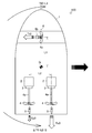
- the schematic plan view which shows the aspect of the thrust which arises from the side thruster and the forward / rearward propeller at the time of the horizontal movement of the ship provided with the boat maneuvering apparatus.
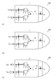
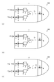
- (A) is a schematic plan view showing an aspect of thrust of the forward and backward propellers corresponding to the rotation operation of the joystick lever
- (B) is an inclination operation among the rotation operation and the inclination operation of the joystick lever.
- FIG. 4C is a schematic plan view showing the thrust of the forward / reverse propellers of both sides.
- FIG. 5C is a diagram illustrating both the rotation operation and the inclination operation of the joystick lever to which the turning operation is applied so as to obtain the turning intended by the operator.
- the schematic plan view which shows the aspect of the thrust of the propeller propeller of a kite.
- the figure which shows the flowchart showing the control aspect of the calibration of turning in the ship provided with the ship maneuvering apparatus.
- (A) is a schematic plan view showing an aspect of thrust of the forward and backward propellers corresponding to the rotation operation of the joystick lever
- (B) is an inclination operation among the rotation operation and the inclination operation of the joystick lever.
- 4C is a schematic plan view showing aspects of thrust and turning moments of the forward and backward propellers on both sides, and (C) shows the rotation operation and the tilting operation of the joystick lever to which the tilting operation is added so as to obtain the intended turning of the driver.
- the schematic plan view which shows the aspect of the thrust of the propeller which moves forward and backward according to both sides.
- a ship 100 in FIG. 1 is a so-called biaxial propulsion type ship (shaft ship).
- the number of propulsion shafts and the type of the propulsion device are not limited to this, and those having a plurality of shafts, an outdrive system, or a POD (pod) system may be used.
- the front-rear and left-right directions are defined with the bow direction of the ship 100 as the front.
- the ship 100 is a shaft ship in which the power of the engine 2 as a power source is transmitted to the forward / rearward propeller 4 through the propeller shaft 4a.
- the hull 1 of the ship 100 includes a propulsion device 17 including an engine 2, a switching clutch 3, a forward and backward propeller 4, a rudder 5, a side thruster 6 and an ECU 16, an accelerator lever 8, a steering handle 9, a joystick lever 10, and a side thruster controller. 11, a monitor 12, a GPS device 13, a heading sensor (direction sensor) 14, and a boat maneuvering device 7 including a boat maneuvering control device 15.
- the two engines 2 generate power for rotating the propeller 4 on the port side and on the starboard side respectively.
- the engines 2 are respectively disposed on the port side rear side and the starboard rear side of the hull 1.
- a switching clutch 3 is connected to the output shaft of the engine 2.
- the two switching clutches 3 output the power transmitted from the output unit of the engine 2 by switching between the forward rotation direction and the reverse rotation direction.
- An output part of the engine 2 is connected to the input side of the switching clutch 3.
- Propeller shafts 4 a are respectively connected to the output side of the switching clutch 3. That is, the switching clutch 3 is configured to transmit power from the engine 2 to the propeller shaft 4a.
- the two forward / reverse propellers 4 generate thrust in the front / rear direction.
- the forward and backward propellers 4 are respectively connected to two propeller shafts 4 a provided so as to penetrate the port bottom and starboard bottom of the hull 1 and reach the outside of the ship.
- the forward / rearward propeller 4 is rotationally driven by the power of the engine 2 transmitted through the propeller shaft 4a, and a plurality of blades arranged around the rotation axis generate thrust by removing surrounding water.
- the two rudders 5 change the direction of the water flow generated by the rotational drive of the forward / reverse propeller 4.
- the rudder 5 is disposed on the port side rear end (stern side) of the hull 1 and on the starboard rear end (stern side) of the hull 1 and behind the forward / rearward propeller 4.
- the rudder 5 is configured to be rotatable in a predetermined angle range in the left-right direction around a rotation axis provided in the hull 1.
- the rudder 5 is connected to the steering handle 9 so as to be interlocked.
- the rudder 5 is configured such that when the rear end portion thereof is directed to the right side of the hull 1 by the operation of the steering handle 9, the stern of the ship 100 is thrust to the left side by the thrust generated by the water flow, and the bow side faces the right side. ing. Similarly, when the rear end of the rudder 5 is turned to the left side of the ship 100 by operating the steering handle 9, the stern of the ship 100 is pushed to the right side by the thrust generated by the water flow, and the bow side is directed to the left side. Yes.
- the side thruster 6 generates thrust in the left-right direction.
- the side thruster 6 is provided on the bow side of the hull 1 and in the center in the left-right direction.
- the side thruster 6 includes a propeller 6a and a motor 6b.
- the motor 6b is configured to be rotatable at a constant rotation speed (unit: rpm), and generates a predetermined thrust by adjusting the drive time and non-drive time of the motor 6b. As the driving time of the motor 6b increases, the generated thrust increases.
- the side thruster 6 is configured such that the thrust generated by the propeller 6 a is directed in the left-right direction of the hull 1.
- the side thruster 6 is driven by a motor 6b based on a signal from the side thruster controller 11, and the propeller 6a is rotated to generate a thrust having an arbitrary magnitude in the left-right direction.
- the motor 6b may be connected to the side thruster controller 11 and configured to be rotatable at an arbitrary number of rotations.
- the accelerator lever 8 constituting the marine vessel maneuvering device 7 generates signals regarding the rotational speed (unit: rpm) of the port forward propeller 4 and the rotational speed of the star forward propeller 4 (unit: rpm) and their rotational directions. To do.
- the accelerator lever 8 includes a lever corresponding to the ported forward / rearward propeller 4 and a lever corresponding to the starboard forward / rearward propeller 4. That is, the accelerator lever 8 is configured to independently generate signals for the port-side forward / backward propeller 4 and starboard-side forward / backward propeller 4.
- the accelerator lever 8 is configured to incline at an arbitrary angle in the longitudinal direction of the ship 100.
- the accelerator lever 8 is configured to independently generate a signal regarding the switching state of the switching clutch 3 corresponding to the rotation speed (unit: rpm) of each engine 2 according to the operation direction and the operation amount.
- the accelerator lever 8 generates a signal of the forward / rear propeller 4 so as to generate a thrust for the ship 100 to move forward when operated to tilt forward, and the ship 100 moves backward when operated to tilt backward.
- a signal of the forward / rearward propeller 4 is generated so as to generate a thrust force.
- the steering handle 9 constituting the boat maneuvering device 7 changes the rotation angle of the rudder 5.
- the steering handle 9 is linked to a rudder 5 of port and starboard via a hydraulic circuit.
- the steering wheel 9 rotates so that the rear end portion of the rudder 5 is directed to the right side.
- the ship 100 is configured such that the stern is pushed to the left side and the bow side faces the right side when the water flow generated by the forward and backward propeller 4 is directed to the right side.
- the rear end of the rudder 5 rotates to the left.
- the ship 100 is configured such that the stern is pushed to the right side when the water flow generated by the forward / rearward propeller 4 is directed to the left side, and the bow side is directed to the left side.
- the joystick lever 10 constituting the boat maneuvering device 7 generates a signal for moving the ship 100 in an arbitrary direction.
- the joystick lever 10 is configured to be able to tilt at an arbitrary angle in an arbitrary direction.
- the joystick lever 10 is configured to be rotatable at an arbitrary angle around the lever axis.
- the joystick lever 10 is configured to generate a signal regarding the rotational speed of the engine 2 and the switching state of the switching clutch 3 and a signal regarding the drive time of the side thruster 6 according to the operation mode and the operation amount. . Specifically, when the joystick lever 10 is operated so as to tilt in an arbitrary direction, a forward and backward propeller for moving the ship 100 in the operation direction with a thrust according to the operation amount and the operation time. 4 and the side thruster 6 are generated. Further, when the joystick lever 10 is operated so as to rotate about the lever shaft, the forward and backward propeller 4 for rotating the ship 100 in an arbitrary direction with a thrust according to the operation amount and the operation time is provided. Generate a signal.
- the joystick lever 10 determines the turning speed and the turning direction of the ship 100.
- the side thruster 6 is configured so that the motor 6b (see FIG. 1) can rotate at an arbitrary rotational speed
- the joystick lever 10 generates a signal for arbitrarily setting the rotational speed of the side thruster 6. To do. In this way, the joystick lever 10 determines the moving speed and moving direction of the ship 100.
- the joystick lever 10 is provided with a lever operation switch 10b that can be operated by the joystick lever 10, and the lever operation switch 10b includes an ON / OFF switch or a tactile switch.
- the lever operation switch 10b When the lever operation switch 10b is enabled by the operation of the operator, the ship 100 is in a state where the joystick lever 10 can be operated.
- the lever operation switch 10b When the lever operation switch 10b is disabled by the operator's operation, the ship 100 is in a state where it cannot be operated even if the joystick lever 10 is operated.
- the side thruster controller 11 constituting the ship maneuvering device 7 drives the side thruster 6.
- the side thruster controller 11 When the side thruster controller 11 is turned on, the side thruster 6 rotates the motor 6b of the side thruster 6 in an arbitrary rotation direction so that a thrust in the left-right direction is generated by the propeller 6a of the side thruster 6.
- a GPS (GPS: Global Positioning System) device 13 that constitutes the boat maneuvering device 7 measures (calculates) the position coordinates of the ship 100.
- the GPS device 13 calculates the position coordinates of the ship 100 by receiving signals from a plurality of GPS satellites, and outputs the current position as latitude La (n) and longitude Lo (n). That is, the GPS device 13 as the position calculating device calculates the absolute value of the position coordinates of the ship 100.
- the heading sensor 14 which is an azimuth calculating device that constitutes the boat maneuvering device 7, measures (calculates) the direction of the ship 100.
- the heading sensor 14 calculates the heading of the ship 100 from the information of the GPS device 13. That is, the heading sensor 14 calculates the absolute heading of the bow of the ship 100.
- the ECU 16 is connected to a fuel metering valve, a fuel injection valve, and various sensors of a fuel supply pump (not shown) of the engine 2, and can control the opening of the fuel metering valve and the opening and closing of the fuel injection valve. It is possible to acquire the information detected by.
- the boat maneuvering control device 15 constituting the boat maneuvering device 7 controls the engine 2, the switching clutch 3, and the side thruster 6 based on detection signals from the accelerator lever 8, the steering handle 9, the joystick lever 10, and the like.
- the boat maneuvering control device 15 is configured to be capable of so-called automatic navigation in which the ship is automatically operated by calculating a route from its own position and a set destination based on information from the GPS device 13.
- the ship maneuvering control device 15 stores various programs and data for controlling the engine 2, the switching clutch 3, and the side thruster 6.
- the boat maneuvering control device 15 can transmit a signal for changing (switching) the clutch state to each switching clutch 3.
- the ship maneuvering control device 15 can transmit signals for controlling the fuel metering valve of the fuel supply pump, the fuel injection valve, and other various devices of the engine 2 to the ECU 16.
- the ship maneuvering control device 15 is connected to the accelerator lever 8 and the joystick lever 10 and can acquire signals from the accelerator lever 8 and the joystick lever 10.
- the boat maneuvering control device 15 is connected to the side thruster controller 11 of the side thruster 6 and can transmit a signal for controlling the side thruster 6.
- the boat maneuvering control device 15 is connected to the GPS device 13 and the heading sensor 14 and can acquire the absolute coordinates and the absolute direction of the ship 100.
- the ship maneuvering control device 15 is connected to the monitor 12 and can display the current position of the ship 100 and the maneuvering status by the joystick lever 10 on the monitor 12.
- the inventor holds the rudder 5 on the port and starboard in a neutral position (that is, a position for causing the ship 100 to go straight), and the propeller of the port and starboard is advanced in a state where the side thruster 6 is not driven. It has been found that the ship 100 turns around the center of gravity G by rotating 4 in the opposite direction by the same number of rotations (in other words, by combining the forward and backward propulsion ratios of the forward and backward propellers 4 of port and starboard). .
- FIG. 4 shows an aspect of thrust generated from the side thruster 6 and the forward / backward propeller 4 of the port side and starboard side when the ship 100 provided with the boat maneuvering device 7 moves laterally.
- a side thruster 6 is provided at a position L1 between the center of gravity from the center of gravity G of the hull 1 having an arbitrary shape toward the bow direction, and the propeller 4 is moved forward and backward on the port side and starboard of the stern. It is assumed that the distance L2 is provided.
- Equation 1 The balance of moments around the center of gravity of the thrust Tt0 by the side thruster 6, the thrust Tp0 by the port forward propeller 4 and the thrust Ts0 by the starboard propeller 4 in the ship 100 is as shown in Equation 1 below. Further, when the average value of the thrust Tp0 and the thrust Ts0 is the reference thrust T0, and the thrust difference between the thrust Tp0 and the thrust Ts0 is ⁇ T0, the relationship between the thrust Tp0 and the thrust Ts0 is as shown in Equations 2 and 3. As a result, the thrust difference ⁇ T0 is expressed as a function of the ratio between the center-of-gravity distance L1 and the inter-axis distance L2 and the thrust Tt0, as shown in Equation 4.
- the turning center intended by the onboard operator does not necessarily match the actual turning center (that is, the center of gravity G of the ship 100).
- the center of gravity G of the ship 100 the position of the maneuvering seat (not shown) or between the bow and stern, the shape of the hull 1, the position of the engine 2, the amount of load, etc.
- the case where the center of gravity G of the hull 1 is located at a position deviated from the position estimated by the operator can be considered.
- an operation different from the action intended by the pilot occurs in the hull 1.
- a turning component is generated at the turning center intended by the operator.
- the inventor can turn the ship 100 on the spot around the turning center intended by the pilot even if the center of gravity G of the hull 1 is located at a position deviated from the position recognized by the pilot. I thought about.
- the inventor increases or decreases the thrust on one of the forward and backward propellers 4 of the port and starboard that generate thrust for turning around the center of gravity G, and the other
- the position of the turning center is set in the longitudinal direction of the hull 1 without causing a turning component at the intended turning center. Found that it can be moved to.
- the rotational speed of the forward and backward propeller 4 of the port and starboard for turning in place of the ship 100 is set.
- the rotational speed of one forward propeller 4 generating thrust backward increases (thrust increases), and the rotational speed of the other forward propeller 4 generating thrust forward decreases.
- the pilot performs calibration of the thrusts of the port prop and forward propeller 4 on the starboard side for each ship 100 on which the boat maneuvering device 7 is mounted.
- the actual turning center can be matched to the intended turning center.
- the boat maneuvering device 7 has a center of the turning center intended by the driver for each thrust of the forward and backward propeller 4 of the port side and starboard side for turning the ship 100 around the center of gravity G. It is possible to store the correction amount of the thrust of the forward / backward propeller 4 of the port side and starboard side that can be turned around. If the turning correction is performed at an arbitrary turning speed, the boat maneuvering device 7 can correct the turning center using this correction amount even when turning at a different turning speed. It becomes possible to turn around the center of the turning that the pilot intends.
- the boat maneuvering device 7 moves the left and right rudder 5 to the neutral position (that is, the position for moving the ship 100 straight) when the operation of the joystick lever 10 is started, including the operation of the switches 10a and 10b. Hold.
- the port propeller propeller according to the clockwise or counterclockwise rotation amount of the joystick lever 10 is rotated. 4 and the thrust Ts1 generated by the starboard forward / reverse propeller 4 are used to rotate the head according to the direction of the rotation operation.
- the motor 6 b of the side thruster 6 does not rotate and no thrust is generated from the side thruster 6 only by rotating the joystick lever 10 for turning the hull 1.
- the side thruster 6 generates a thrust according to the operation time of the tilt operation of the joystick lever 10 for the oblique movement and the lateral movement of the hull 1.
- the joystick In order to move the actual turning center from the position of the center of gravity G to the intended turning center (for example, closer to the bow), the joystick is rotated at a tilt angle at which the ship 100 turns around the intended turning center.
- the lever 10 is tilted forward.
- the joystick lever 10 In order to move the actual turning center further toward the stern side, the joystick lever 10 is tilted backward at an inclination angle at which the ship 100 turns around the intended turning center together with the rotation operation.
- the thrust correction amount Tpr ⁇ Tsr is converted into the thrust Tp1 ⁇ Ts1 by the forward / backward propeller 4 for turning the starboard and starboard for turning.
- Vector addition is performed (see FIG. 5A).
- the correction amounts Tpr and Tsr shown in FIG. 5B are thrusts that move the ship 100 forward, and thrusts Tp1 and Ts1 that are generated by the forward and backward propeller 4 that makes the ship 100 turn around the center of gravity G.
- this is a thrust force that moves the actual turning center from the position of the center of gravity G to the side of the bow.
- Such a correction amount Tpr ⁇ Tsr is added to the thrust Tp1 ⁇ Ts1 generated by the forward / backward propeller 4 of the port side and starboard side so that, as shown in FIG. Turn around. That is, the ship 100 turns around the turning center Ci by the thrust Tpn generated by the port-side forward and backward propeller 4 and the thrust Tsn generated by the starboard forward-and-back propeller 4 according to the rotation amount and the inclination angle of the joystick lever 10. In this way, the actual turning center moves from the center of gravity G in the front-rear direction of the hull 1, so that the ship 100 can turn around the turning center Ci intended by the operator.
- boat maneuvering device 7 may include other operation means (not shown) in addition to the joystick lever 10.
- the pilot can carry out the calibration for turning by operating another operating means instead of the tilting operation with respect to the rotating operation of the joystick lever 10.
- an arrow indicating the forward direction and an arrow indicating the backward direction of the hull 1 are displayed on the touch panel monitor 12 (see FIG. 1) (not shown).
- the thrust by the forward and backward propeller 4 of the port side and starboard side changes so as to advance the ship 100 forward.
- the thrust by the forward and backward propeller 4 of the port side and the starboard side changes so as to move the ship 100 backward.
- the touch operation on the two arrows at the time of turning calibration is a predetermined operation for moving the ship 100 forward or backward.
- a button for moving the ship 100 forward and a button for moving the ship 100 backward may be provided in the vicinity of the above-mentioned maneuvering seat for the operator to sit (not shown).
- the operation on the two buttons at the time of calibration for turning is a predetermined operation for moving the ship 100 forward or backward.
- step S11 when the boat maneuvering control device 15 obtains a signal for instructing the start of the turning calibration from the joystick lever 10, it changes to a mode for performing the turning correction (referred to as a turning mode).
- a turning mode a mode for performing the turning correction
- step S12 the boat maneuvering control device 15 obtains a signal corresponding to either the clockwise or counterclockwise rotation direction and the rotation amount of the joystick lever 10 that is rotated around the lever axis at predetermined time intervals. The step moves to step S13.
- step S13 When the boat maneuvering control device 15 acquires a signal indicating that the joystick lever 10 is rotated, in step S13, a thrust difference ⁇ T1 is generated between the forward propeller 4 and the forward propeller 4 between the port and starboard in accordance with the rotation direction and the rotation amount. Then, the port propeller 4 is rotated at a rotational speed Np1, which is the rotational speed at which the thrust Tp1 is generated, and the starboard forward propeller 4 is rotated at the rotational speed Ns1, which is the rotational speed at which the thrust Ts1 is generated. In a state in which the occurrence of the error occurs, the step proceeds to step S14.
- step S14 the boat maneuvering control device 15 determines whether or not the calibration execution switch 10a (see FIG. 3) is turned on.
- the boat maneuvering control device 15 shifts the step to step S17 when determining Yes, and shifts the step to step S15 when determining No.
- step S15 the boat maneuvering control device 15 acquires a signal corresponding to the tilt direction and the tilt angle of the joystick lever 10 that has been tilted together with a signal corresponding to the rotation direction and the rotation amount of the joystick lever 10 at predetermined time intervals. Then, the step is shifted to step S16.
- the boat maneuvering control device 15 sends a signal corresponding to the rotation direction and the rotation amount of the joystick lever 10 in step S15.
- the signal corresponding to the operation of the other operation means described above may be acquired every predetermined time. After the acquisition, the boat maneuvering control device 15 shifts the step to step S16.
- the boat maneuvering control device 15 responds to a signal corresponding to the touch operation to the arrow indicating the forward direction and a touch operation to the arrow indicating the backward direction together with the signal corresponding to the rotation direction and the rotation amount of the joystick lever 10. It is also possible to obtain a signal.
- the boat maneuvering control device 15 includes a signal corresponding to the operation of the button for moving the boat 100 forward and a signal corresponding to the operation of the button for moving the boat 100 backward together with a signal corresponding to the rotation direction and the rotation amount of the joystick lever 10. May be obtained.
- step S16 the boat maneuvering control device 15 sets the port side so that a thrust difference ⁇ Tn is generated between the propeller 4 and the forward propeller 4 between the port side and the starboard according to the rotation direction, the rotation amount, the inclination direction, and the inclination angle of the joystick lever 10.
- the forward / reverse propeller 4 is rotated at a rotational speed Npn which is the rotational speed at which the thrust Tpn is generated, and the starboard forward / rearward propeller 4 is rotated at the rotational speed Nsn at which the thrust Tsn is generated, resulting in a rotational speed difference ⁇ Nn.
- step S14 the process proceeds to step S14.
- the boat maneuvering control device 15 repeats the steps S14 to S16 until it determines Yes in step S14. While the steps S14 to S16 are repeated, the driver determines that the desired turning is not yet obtained with respect to the rotation direction, rotation amount, tilt direction, and tilt angle of the joystick lever 10. . That is, while the steps S14 to S16 are repeated, the signal acquired by the boat maneuvering control device 15 in step S15 is a thrust (or hull 1) that expresses the turning operation centered on the turning center unintended by the operator. It can be said that this is a signal for generating a thrust that generates a forward / backward movement motion.
- the calibration execution switch 10a is used when the operator determines that a desired turn is obtained with respect to the rotation direction and rotation amount of the joystick lever 10 or with respect to the rotation direction, rotation amount, inclination direction and inclination angle.
- the boat maneuvering control device 15 can determine Yes in step S14. That is, when the boat maneuvering control device 15 determines Yes in step S14, the signal acquired by the boat maneuvering control device 15 in step S12 or step S15 is a signal for generating a thrust to obtain a desired turning, that is, the operator It can be said that this is a signal that generates a thrust that expresses the turning motion centered on the intended turning center Ci.
- the boat maneuvering device 7 rotates the port and starboard forward and backward propellers 4 in accordance with the amount of rotation of the joystick lever 10 to rotate around the desired turning center Ci.
- the rotational speeds of the forward and backward propellers 4 on the port side and starboard side are changed according to the inclination angle of the inclination operation of the joystick lever 10 operated so that the ship 100 turns.
- step S17 when the boat maneuvering control device 15 acquires a signal from the calibration execution switch 10a, the step is shifted to step S18.
- step S18 the boat maneuvering control device 15 corresponds to the inclination angle of the inclination operation at the time point with respect to the rotational speed Npn of the port propeller 4 propeller 4 generated at the determination time point of step S14 or the acquisition time point of step S17.
- the rotation speed Npni of the port forward / reverse propeller is set as a correction value.
- the marine vessel maneuvering control device 15 uses the starboard corresponding to the tilt angle of the tilting operation at the time point for the rotational speed Nsn of the starboard forward / reverse propeller 4 generated at the determination time of step S14 or the acquisition time of step S17.
- the forward / reverse propeller speed Nsni is set as a correction value.
- the marine vessel maneuvering control device 15 moves the port and starboard forward and backward corresponding to the inclination angle of the tilt operation at the time point out of the thrust generated by the rotation speeds Npn and Nsn of the port and starboard propeller 4.
- the thrust generated by each rotation speed Npni / Nsni of the propeller is set as a correction coefficient Cp / Cs for the movement of the center of rotation.
- the boat maneuvering device 7 generates a thrust force based on the rotational speeds Npn and Nsn of the port and starboard forward and backward propellers 4 necessary for a desired turn by combining the rotation operation and the tilt operation of the joystick lever 10.
- appropriate correction coefficients Cp and Cs are set.
- the boat maneuvering control device 15 shifts the step to step S19.
- step S19 the marine vessel maneuvering control device 15 sets the port corresponding to the rotation amount of the rotation operation of the joystick lever 10 at the determination time of step S14 or the acquisition time of step S17, or the rotation amount of the rotation operation of the joystick lever 10 at the time point.
- the forward and backward propeller speeds Npnr and Nsnr are stored together with the set correction coefficients Cp and Cs, and the step ends.
- step S17 If the process proceeds to step S17 after passing through steps S11 to S14 without going through steps S15 and S16, the signal acquisition time in step S12 or the determination time in step S14 in step S19.
- the joystick lever 10 corresponding to the amount of rotation of the joystick lever 10 at the rotational speed Np1 of the ported forward / backward propeller 4 and the rotational speed Ns1 of the starboard forward / backward propeller 4 are used as the correction coefficients Cp and Cs, respectively. It is memorized with the rotation amount.
- the boat maneuvering device 7 uses the correction coefficients Cp and Cs to move the port and starboard forward and backward propellers according to the rotation amount of the rotation operation.
- the thrust according to each rotation speed of 4 is generated.
- the boat maneuvering control device 15 adds a function including a quantitative correction coefficient Cp to the rotation speed before calibration of the port-side forward / rearward propeller 4 corresponding to an arbitrary rotation amount of the rotation operation of the joystick lever 10. As a result, the rotational speed of the forward / backward propeller 4 on the port side is changed.
- the boat maneuvering control device 15 adds a function including a quantitative correction coefficient Cs to the rotation speed before calibration of the starboard forward / reverse propeller 4 corresponding to an arbitrary rotation amount of the rotation operation of the joystick lever 10. The rotational speed of the starboard propeller 4 is changed.
- the boat maneuvering control device 15 includes the correction coefficient Cp / Cs in each thrust by the rotational speed before calibration of the forward / backward propeller 4 of the port and starboard corresponding to an arbitrary amount of rotation of the joystick lever 10.
- the thrusts of the forward and backward propellers 4 on the port side and starboard side are changed by vector addition of the functions.
- the boat maneuvering control device 15 can change the rotational speeds of the forward and backward propellers 4 on the port side and starboard side according to the change in the rotation amount of the joystick lever 10 by using the correction coefficients Cp and Cs. .
- step S17 after passing through steps S11 to S14 without passing through step S15 and step S16, the boat maneuvering control device 15 sets the rotation amount of the rotation operation of the joystick lever 10 to each rotation amount. Respective rotation speeds before calibration of the corresponding port and starboard forward and backward propellers 4 are continuously used.
- the forward / reverse propulsion ratio refers to the ratio of the reverse thrust to the forward thrust.
- the rotational speed of the forward and backward propeller 4 of the port and starboard for turning in place of the ship 100 is set.
- the forward / reverse propulsion ratio is changed by increasing the thrust of the forward / reverse propeller generating the reverse thrust or decreasing the thrust of the forward propeller generating the forward thrust.
- the forward / reverse propulsion ratio is changed by decreasing the thrust of the forward / reverse propeller generating the reverse thrust or increasing the thrust of the forward / rear propeller generating the forward thrust.
- the joystick lever 10 is tilted at an inclination angle at which the ship 100 turns around the center.
- the correction amount Ff is vector-added to the thrust T1c of the ported forward / rearward propeller 4 so that the portered forward / rearward propeller 4 is shown in FIG. Generates a thrust T1e changed from the thrust T1c.
- the correction amount Ff may be subtracted from the thrust T2c of the starboard forward / rear propeller 4 instead of adding the correction amount Ff to the thrust T1c of the leftward propeller propeller 4.
- the forward / reverse propulsion ratio is changed, and the vehicle can turn around the turning center Ci intended by the operator.
- the boat maneuvering control device 15 sets the thrust (that is, the correction amount Ff) generated according to the changed forward / reverse propulsion ratio as a correction coefficient, and stores the correction coefficient. After the turning calibration is completed, the boat maneuvering control device 15 determines which of the thrusts depends on the rotational speed before calibration of the forward and backward propeller 4 of the port and starboard corresponding to an arbitrary amount of rotation of the joystick lever 10. On the other hand, the thrust of one forward / rearward propeller 4 is changed by vector addition of a function including this correction coefficient.
- the operation of moving the ship 100 forward or backward is not limited to the tilting operation of the joystick lever 10, and may be a predetermined operation by the above-described operating means.
- turning calibration can be easily performed so that a desired turning can be obtained for each pilot on board. Therefore, each pilot can easily obtain a desired turn without knowing the position of the center of gravity G of the ship 100, the shape of the hull 1, and the like.
- the present invention can be used for a ship maneuvering apparatus.
Landscapes
- Chemical & Material Sciences (AREA)
- Engineering & Computer Science (AREA)
- Combustion & Propulsion (AREA)
- Mechanical Engineering (AREA)
- Ocean & Marine Engineering (AREA)
- Mechanical Control Devices (AREA)
Priority Applications (2)
| Application Number | Priority Date | Filing Date | Title |
|---|---|---|---|
| US16/090,480 US10787238B2 (en) | 2016-03-31 | 2016-10-13 | Ship handling device |
| EP16897019.2A EP3437986B1 (de) | 2016-03-31 | 2016-10-13 | Verfahren zur verwendung eines schiffsteuerungsvorrichtung |
Applications Claiming Priority (2)
| Application Number | Priority Date | Filing Date | Title |
|---|---|---|---|
| JP2016-073355 | 2016-03-31 | ||
| JP2016073355A JP6430988B2 (ja) | 2016-03-31 | 2016-03-31 | 操船装置 |
Publications (1)
| Publication Number | Publication Date |
|---|---|
| WO2017168802A1 true WO2017168802A1 (ja) | 2017-10-05 |
Family
ID=59963816
Family Applications (1)
| Application Number | Title | Priority Date | Filing Date |
|---|---|---|---|
| PCT/JP2016/080442 Ceased WO2017168802A1 (ja) | 2016-03-31 | 2016-10-13 | 操船装置 |
Country Status (4)
| Country | Link |
|---|---|
| US (1) | US10787238B2 (de) |
| EP (1) | EP3437986B1 (de) |
| JP (1) | JP6430988B2 (de) |
| WO (1) | WO2017168802A1 (de) |
Cited By (1)
| Publication number | Priority date | Publication date | Assignee | Title |
|---|---|---|---|---|
| WO2019081405A1 (en) * | 2017-10-23 | 2019-05-02 | Rolls-Royce Ab | NAVIGATION SYSTEM WITH INDEPENDENT LATERAL AND LONGITUDINAL PUSH CONTROL |
Families Citing this family (19)
| Publication number | Priority date | Publication date | Assignee | Title |
|---|---|---|---|---|
| US10534092B2 (en) * | 2017-06-01 | 2020-01-14 | Tesla, Inc. | Technologies for vehicle positioning |
| JP7018008B2 (ja) | 2018-10-25 | 2022-02-09 | ヤンマーパワーテクノロジー株式会社 | パネル取付器具及び船舶用の操作パネル構造 |
| US10926855B2 (en) * | 2018-11-01 | 2021-02-23 | Brunswick Corporation | Methods and systems for controlling low-speed propulsion of a marine vessel |
| JP7060491B2 (ja) * | 2018-11-02 | 2022-04-26 | ヤンマーパワーテクノロジー株式会社 | 船舶用ハイブリッドシステム |
| US11958583B2 (en) | 2019-06-06 | 2024-04-16 | Nhk Spring Co., Ltd. | Automatic setting device, automatic setting method, and program |
| US11480966B2 (en) * | 2020-03-10 | 2022-10-25 | Brunswick Corporation | Marine propulsion control system and method |
| NL2025284B1 (en) * | 2020-04-06 | 2021-10-25 | Demcon Unmanned Systems B V | Watercraft comprising a positioning system |
| JP2023074297A (ja) * | 2021-11-17 | 2023-05-29 | ヤマハ発動機株式会社 | 船舶用ステアリング機構を備える船舶及び船舶用ステアリングハンドル |
| JP2023092071A (ja) * | 2021-12-21 | 2023-07-03 | ヤマハ発動機株式会社 | 船舶及び船舶推進制御システム |
| US12065230B1 (en) | 2022-02-15 | 2024-08-20 | Brunswick Corporation | Marine propulsion control system and method with rear and lateral marine drives |
| CN115111495A (zh) * | 2022-07-15 | 2022-09-27 | 中船黄埔文冲船舶有限公司 | 一种船用操纵杆遥控站旋转支架 |
| US12258115B2 (en) | 2022-07-20 | 2025-03-25 | Brunswick Corporation | Marine propulsion system and joystick control method |
| US12134454B1 (en) | 2022-07-20 | 2024-11-05 | Brunswick Corporation | Marine propulsion system and method with single rear drive and lateral marine drive |
| US12110088B1 (en) | 2022-07-20 | 2024-10-08 | Brunswick Corporation | Marine propulsion system and method with rear and lateral marine drives |
| JP7841392B2 (ja) * | 2022-08-29 | 2026-04-07 | スズキ株式会社 | 操船システム、制御パラメータの設定方法 |
| JP2024060163A (ja) | 2022-10-19 | 2024-05-02 | ヤマハ発動機株式会社 | 船舶推進システムおよび船舶 |
| JP2024068486A (ja) * | 2022-11-08 | 2024-05-20 | ヤマハ発動機株式会社 | 船舶推進システムおよびそれを備える船舶 |
| JP2025025666A (ja) * | 2023-08-10 | 2025-02-21 | ヤマハ発動機株式会社 | 船舶推進システムおよび船舶 |
| US20250282460A1 (en) * | 2024-03-08 | 2025-09-11 | Kawasaki Motors, Ltd. | Small watercraft and control method of watercraft |
Citations (4)
| Publication number | Priority date | Publication date | Assignee | Title |
|---|---|---|---|---|
| JPS628900A (ja) * | 1985-07-06 | 1987-01-16 | Tokyo Keiki Co Ltd | 操船装置 |
| JP2010126085A (ja) * | 2008-11-28 | 2010-06-10 | Yamaha Motor Co Ltd | 操船支援装置およびそれを備えた船舶 |
| JP2012185154A (ja) * | 2011-02-14 | 2012-09-27 | Dgs Computer:Kk | Gps信号による移動体制御装置、移動体制御方法、移動体制御プログラムおよびこれを用いた移動局管理システム、移動局管理方法、移動局管理プログラム |
| JP2013014173A (ja) * | 2011-06-30 | 2013-01-24 | Yanmar Co Ltd | 船舶操船装置 |
Family Cites Families (8)
| Publication number | Priority date | Publication date | Assignee | Title |
|---|---|---|---|---|
| JP2801174B2 (ja) * | 1996-09-02 | 1998-09-21 | 日本操舵システム株式会社 | 電気推進装置と二枚舵装置とからなる船舶推進装置における船速切換方法 |
| EP1187760B1 (de) * | 1999-06-24 | 2004-04-14 | Siemens Aktiengesellschaft | Antriebs- und fahrsystem für schiffe |
| JP4666152B2 (ja) * | 2005-07-20 | 2011-04-06 | トヨタ自動車株式会社 | 船艇の操船装置 |
| WO2007030040A1 (en) * | 2005-09-06 | 2007-03-15 | Cpac Systems Ab | A method for arrangement for calibrating a system for controlling thrust and steering in a watercraft |
| JP5337722B2 (ja) * | 2010-01-07 | 2013-11-06 | ヤマハ発動機株式会社 | 船舶用推進制御装置および船舶 |
| JP5289485B2 (ja) * | 2011-03-07 | 2013-09-11 | 三菱電機株式会社 | 多機掛け船舶推進機の制御装置 |
| EP2727819B1 (de) | 2011-06-28 | 2019-09-04 | Yanmar Co., Ltd. | Schiffsteuerungsvorrichtung und schiffsteuerungsverfahren |
| JP5944274B2 (ja) * | 2012-08-31 | 2016-07-05 | ヤンマー株式会社 | アウトドライブ装置用操船システム |
-
2016
- 2016-03-31 JP JP2016073355A patent/JP6430988B2/ja active Active
- 2016-10-13 WO PCT/JP2016/080442 patent/WO2017168802A1/ja not_active Ceased
- 2016-10-13 US US16/090,480 patent/US10787238B2/en active Active
- 2016-10-13 EP EP16897019.2A patent/EP3437986B1/de active Active
Patent Citations (4)
| Publication number | Priority date | Publication date | Assignee | Title |
|---|---|---|---|---|
| JPS628900A (ja) * | 1985-07-06 | 1987-01-16 | Tokyo Keiki Co Ltd | 操船装置 |
| JP2010126085A (ja) * | 2008-11-28 | 2010-06-10 | Yamaha Motor Co Ltd | 操船支援装置およびそれを備えた船舶 |
| JP2012185154A (ja) * | 2011-02-14 | 2012-09-27 | Dgs Computer:Kk | Gps信号による移動体制御装置、移動体制御方法、移動体制御プログラムおよびこれを用いた移動局管理システム、移動局管理方法、移動局管理プログラム |
| JP2013014173A (ja) * | 2011-06-30 | 2013-01-24 | Yanmar Co Ltd | 船舶操船装置 |
Cited By (3)
| Publication number | Priority date | Publication date | Assignee | Title |
|---|---|---|---|---|
| WO2019081405A1 (en) * | 2017-10-23 | 2019-05-02 | Rolls-Royce Ab | NAVIGATION SYSTEM WITH INDEPENDENT LATERAL AND LONGITUDINAL PUSH CONTROL |
| CN111465554A (zh) * | 2017-10-23 | 2020-07-28 | 康斯伯格海事瑞典股份公司 | 独立控制横向和纵向推力的航行系统 |
| US11526169B2 (en) | 2017-10-23 | 2022-12-13 | Kongsberg Maritime Sweden Ab | Navigation system with independent control of lateral and longitudinal thrust |
Also Published As
| Publication number | Publication date |
|---|---|
| US20190112021A1 (en) | 2019-04-18 |
| EP3437986B1 (de) | 2020-06-03 |
| EP3437986A1 (de) | 2019-02-06 |
| US10787238B2 (en) | 2020-09-29 |
| JP6430988B2 (ja) | 2018-11-28 |
| JP2017178290A (ja) | 2017-10-05 |
| EP3437986A4 (de) | 2019-04-24 |
Similar Documents
| Publication | Publication Date | Title |
|---|---|---|
| JP6430988B2 (ja) | 操船装置 | |
| JP6250520B2 (ja) | 操船装置 | |
| JP5133637B2 (ja) | 船舶 | |
| JP5481059B2 (ja) | 操船支援装置およびそれを備えた船舶 | |
| JP6521527B2 (ja) | 船舶用操船装置及びそれを備えた船舶 | |
| JP6596700B2 (ja) | 操船装置 | |
| JP6421111B2 (ja) | 操船装置 | |
| EP1775212A2 (de) | Verfahren zum Manövrieren eines Wasserfahrzeuges und Wasserfahrzeug | |
| EP1775211A2 (de) | Verfahren zum Positionieren eines Wasserfahrzeuges und Wasserfahrzeug | |
| JP7664060B2 (ja) | 操船装置、及び船舶 | |
| JP2006001432A (ja) | 小型船舶用ステアリング装置 | |
| WO2016063610A1 (ja) | 操船装置 | |
| WO2013001875A1 (ja) | 船舶操船装置及び船舶の操船方法 | |
| WO2017135304A1 (ja) | ジョイスティックコントロール装置 | |
| JP2008174173A (ja) | バウスラスタを有する2軸2舵船の推力制御方法及び装置 | |
| JPWO2019069382A1 (ja) | 操船支援装置 | |
| JP2013014173A (ja) | 船舶操船装置 | |
| JP6379388B2 (ja) | 操船装置 | |
| JP2025025729A (ja) | 船舶推進システムの制御装置および方法、船舶 | |
| JP6262633B2 (ja) | 操船装置 | |
| US12473068B2 (en) | Marine propulsion system and marine vessel | |
| US20250236380A1 (en) | Boat control system and boat | |
| JP2022146792A (ja) | 操船システム及び船舶 | |
| JP2019018701A (ja) | 船体用制御装置、船体、船体の操作方法 |
Legal Events
| Date | Code | Title | Description |
|---|---|---|---|
| NENP | Non-entry into the national phase |
Ref country code: DE |
|
| WWE | Wipo information: entry into national phase |
Ref document number: 2016897019 Country of ref document: EP |
|
| ENP | Entry into the national phase |
Ref document number: 2016897019 Country of ref document: EP Effective date: 20181031 |
|
| 121 | Ep: the epo has been informed by wipo that ep was designated in this application |
Ref document number: 16897019 Country of ref document: EP Kind code of ref document: A1 |