WO2017168832A1 - 分水栓取付用治具 - Google Patents
分水栓取付用治具 Download PDFInfo
- Publication number
- WO2017168832A1 WO2017168832A1 PCT/JP2016/085338 JP2016085338W WO2017168832A1 WO 2017168832 A1 WO2017168832 A1 WO 2017168832A1 JP 2016085338 W JP2016085338 W JP 2016085338W WO 2017168832 A1 WO2017168832 A1 WO 2017168832A1
- Authority
- WO
- WIPO (PCT)
- Prior art keywords
- roller
- diameter
- diameter expansion
- water
- water faucet
- Prior art date
- Legal status (The legal status is an assumption and is not a legal conclusion. Google has not performed a legal analysis and makes no representation as to the accuracy of the status listed.)
- Ceased
Links
Images


Classifications
-
- F—MECHANICAL ENGINEERING; LIGHTING; HEATING; WEAPONS; BLASTING
- F16—ENGINEERING ELEMENTS AND UNITS; GENERAL MEASURES FOR PRODUCING AND MAINTAINING EFFECTIVE FUNCTIONING OF MACHINES OR INSTALLATIONS; THERMAL INSULATION IN GENERAL
- F16L—PIPES; JOINTS OR FITTINGS FOR PIPES; SUPPORTS FOR PIPES, CABLES OR PROTECTIVE TUBING; MEANS FOR THERMAL INSULATION IN GENERAL
- F16L41/00—Branching pipes; Joining pipes to walls
- F16L41/04—Tapping pipe walls, i.e. making connections through the walls of pipes while they are carrying fluids; Fittings therefor
- F16L41/06—Tapping pipe walls, i.e. making connections through the walls of pipes while they are carrying fluids; Fittings therefor making use of attaching means embracing the pipe
-
- E—FIXED CONSTRUCTIONS
- E03—WATER SUPPLY; SEWERAGE
- E03B—INSTALLATIONS OR METHODS FOR OBTAINING, COLLECTING, OR DISTRIBUTING WATER
- E03B7/00—Water main or service pipe systems
- E03B7/02—Public or like main pipe systems
-
- F—MECHANICAL ENGINEERING; LIGHTING; HEATING; WEAPONS; BLASTING
- F16—ENGINEERING ELEMENTS AND UNITS; GENERAL MEASURES FOR PRODUCING AND MAINTAINING EFFECTIVE FUNCTIONING OF MACHINES OR INSTALLATIONS; THERMAL INSULATION IN GENERAL
- F16L—PIPES; JOINTS OR FITTINGS FOR PIPES; SUPPORTS FOR PIPES, CABLES OR PROTECTIVE TUBING; MEANS FOR THERMAL INSULATION IN GENERAL
- F16L41/00—Branching pipes; Joining pipes to walls
- F16L41/08—Joining pipes to walls or pipes, the joined pipe axis being perpendicular to the plane of a wall or to the axis of another pipe
- F16L41/082—Non-disconnectable joints, e.g. soldered, adhesive or caulked joints
-
- F—MECHANICAL ENGINEERING; LIGHTING; HEATING; WEAPONS; BLASTING
- F16—ENGINEERING ELEMENTS AND UNITS; GENERAL MEASURES FOR PRODUCING AND MAINTAINING EFFECTIVE FUNCTIONING OF MACHINES OR INSTALLATIONS; THERMAL INSULATION IN GENERAL
- F16L—PIPES; JOINTS OR FITTINGS FOR PIPES; SUPPORTS FOR PIPES, CABLES OR PROTECTIVE TUBING; MEANS FOR THERMAL INSULATION IN GENERAL
- F16L41/00—Branching pipes; Joining pipes to walls
- F16L41/08—Joining pipes to walls or pipes, the joined pipe axis being perpendicular to the plane of a wall or to the axis of another pipe
- F16L41/088—Joining pipes to walls or pipes, the joined pipe axis being perpendicular to the plane of a wall or to the axis of another pipe fixed using an elastic grommet between the extremity of the tube and the wall
-
- E—FIXED CONSTRUCTIONS
- E03—WATER SUPPLY; SEWERAGE
- E03B—INSTALLATIONS OR METHODS FOR OBTAINING, COLLECTING, OR DISTRIBUTING WATER
- E03B9/00—Methods or installations for drawing-off water
- E03B9/02—Hydrants; Arrangements of valves therein; Keys for hydrants
- E03B9/08—Underground hydrants
- E03B9/12—Stand-pipes
Definitions
- This invention relates to a technology of a water faucet mounting jig in which a water faucet is provided at a water outlet provided by drilling a peripheral wall of a water pipe.
- a water pipe for passing water taken from a river or the like is buried in order to supply water to buildings such as factories, offices, and homes.
- a water diverter is drilled in the peripheral wall of the water pipe by a drill equipped with a drill, and a water distiller integrally provided with a metal sleeve or the sleeve is attached to the peripheral edge of the water diverter together with the rubber packing.
- one end opening of a metal sleeve is connected to a water pipe in order to lock and fix a sleeve portion integrally formed with a metal sleeve or a water faucet (hereinafter also simply referred to as a metal sleeve) to a water distribution port.
- a metal sleeve protruded into the water pipe by a diameter expanding head provided at the tip of the main shaft of the jig inserted into the metal sleeve and a diameter expanding roller inclined thereto.
- the front end portion is bent so as to be turned to the outer periphery, and the opening front end portion of the metal sleeve is caulked to the water distribution port of the water pipe.
- the water faucet constituted by the diameter expansion head provided at the tip of the main shaft and the diameter expansion roller provided obliquely thereto as described above. It is known that a mounting jig is used.
- the jig operation is performed by adjusting a drum-shaped diameter-expanding roller obliquely provided on a diameter-expansion head at the front end of the main shaft while manually moving the main shaft up and down.
- the water faucet is engaged and caulked to lock and fix the water faucet to the water outlet, and the water inlet is sealed securely.
- the metal sleeve when the peripheral edge of the opening of the metal sleeve is bent by the expansion roller with a strong rotational force of the main shaft, the metal sleeve sometimes has a bellows-like buckling, so-called lantern buckling, due to the upward pushing force of the expansion roller. There was a case.
- the folded edge of the cylindrical rubber packing interposed between the sleeve folded inside the water pipe outlet edge and the inner peripheral surface of the water pipe is likely to be damaged, and the sealing function may be lowered. occured.
- the diameter-expanding roller has a drum shape that only bends the peripheral edge of the opening of the metal sleeve, the edge flange of the roller is deformed outward, and the inner surface of the roller housing formed on the diameter expansion head and the edge flange are The roller comes into contact with the roller and cannot rotate.
- the metal sleeve is plastically deformed only by the taper portion of the roller, the diameter expansion force becomes large, and the collar portion of the diameter expansion roller tilts and the shim wears out. Further, even if a shim is pasted to give a predetermined spacer function to the roller end face, the shim cannot be joined accurately, and the accurate spacer function cannot be exhibited.
- the present invention has been made in view of such circumstances, and can reduce the pressing and expanding force of the expanding roller to prevent buckling, and shims are formed on both end surfaces of the expanding roller. And a water faucet mounting jig that can confirm the amount of folded deformation of the metal sleeve from the outside.
- the diameter expansion roller is formed in a drum-shaped concave portion, and the concave portion is inclined.
- the substantially upper half of the enlarged diameter roller provided was formed in a substantially tapered portion, and the substantially lower half was formed in a rounded portion.
- the water faucet mounting jig according to the present invention is also characterized by the following points.
- the inclination angle of the tapered portion of the inclined diameter-expanding roller is within the range of a depression angle of 65 to 77 degrees with respect to a virtual straight line orthogonal to the axis of the eccentric movable shaft.
- the diameter-expansion roller has a starting end collar portion with which a sleeve tip abuts at the upper end side of the concave portion at the start of diameter expansion of the sleeve, and a friction portion is formed on the starting end collar portion.
- a friction structure that generates a frictional force is formed at a predetermined interval around the periphery of the start edge.
- the friction structure is formed from the starting end collar to the upper region of the tapered portion, and the groove depth of the valley structure of the friction part formed by the friction structure is from the starting end collar. Reduce gradually over the taper.
- the crest end of the above-mentioned ridge / valley structure is blunt.
- Concave grooves are formed on the upper end surface and the lower end surface of the diameter expanding roller, and shims are fitted into the concave grooves.
- a diameter expansion amount detection mechanism is provided at the base end operation portion of the roller shaft in which the diameter expansion roller is continuously provided at the tip, and the diameter expansion amount The detection mechanism is configured to display the ascending amount and rotation amount of the roller shaft as the amount of diameter expansion by the scale of the diameter expansion amount detection nut.
- the concave portion of the diameter expanding roller is a tapered portion in the upper half and a rounded portion in the lower half
- the metal sleeve is first expanded while being elastically deformed lightly and linearly at the tapered portion, and thereafter
- it since it is plastically deformed into a round shape at the rounded portion, it becomes a tapered shape that traces a semicircular arc, and the engagement with the end of the water diverting port is ensured and the sealing function of the rubber packing can be sufficiently fulfilled.
- the angle of the diameter expansion roller shaft is increased, the diameter expansion force applied to the terminal flange increases, and if the angle is decreased, the diameter decreases, so that the angle can be adjusted according to the required diameter expansion force.
- the taper part elastically deforms the opening end of the metal sleeve until just before the plastic deformation, and in that state, the metal sleeve is finally expanded at the rounded part of the diameter expansion roller and folded back while being plastically deformed.
- the pressure applied to the chamber and the outer periphery of the roller shaft is reduced. Therefore, it is also suitable for work requiring a large diameter expansion force, such as branch work using a water pipe having a large branch diameter and a large pipe thickness.
- the tilt angle of the tapered portion of the roller is adjusted within a range of 65 to 77 degrees with respect to a virtual straight line perpendicular to the axis of the eccentric movable shaft. Then, the diameter expansion force can be reduced, and the pressure of the roller applied to the inner wall of the roller housing can be adjusted by changing the angle with the shaft. In particular, when the inclination of the roller shaft is increased, the force applied to the end collar of the enlarged diameter roller is increased, and when the inclination of the roller shaft is decreased, the force applied to the end flange of the roller is decreased.
- the diameter expansion force due to the taper portion of the diameter expansion roller applies deformation stress to the lower end of the metal sleeve along the roller axis, but does not become a large force that causes plastic deformation like the radius portion. Plastic deformation can be reliably and accurately performed in a round shape.
- the diameter expansion stress at the taper part pushes the diameter expansion roller in the direction of the starting end collar
- the diameter expansion stress at the radius part pushes the diameter expansion roller in the direction of the end collar part.
- the value obtained by subtracting the elastic deformation force generated by the tapered portion from the plastic deformation force is the pressure applied to the inner wall of the roller housing, and the pressure load can be reduced.
- the bending force of the roller shaft and the main shaft can be reduced, and the roller shaft and the main shaft can be well balanced.
- the diameter-expansion operation can be performed with a small force, the consumption of shims and the like is reduced, and deformation of the start end collar and end collar of the diameter expansion roller does not occur.
- the diameter-expanding roller includes, on the upper end side of the concave portion, a start end collar portion with which the sleeve tip abuts when the sleeve starts to expand, and a friction portion is formed on the start end collar portion. Since the diameter expansion force of the diameter expansion roller can be accurately transmitted to the sleeve and the slip is suppressed, the diameter expansion roller can be forcibly rotated and the occurrence of seizure can be prevented. Moreover, generation
- the rotational force of the diameter expansion handle can be efficiently transmitted to the diameter expansion roller, the force in the pulling direction applied to the diameter expansion roller can be reduced, and the life such as wear of members around the diameter expansion roller can be extended. be able to.
- the expansion roller is seized and does not rotate, the diameter cannot be expanded unless a large force is applied to the expansion handle, but the force applied to the expansion handle is reduced by eliminating the seizure of the expansion roller. be able to.
- roller shape can be reduced, and the diameter expansion head can be made compact.
- the friction portion can reliably follow the rotation of the diameter expanding roller in the circumferential direction of the sleeve inner surface.
- the sliding resistance of the sleeve along the concave portion of the diameter expansion roller can be suppressed as much as possible, and the burden on the diameter expansion roller and the burden on the peripheral members of the diameter expansion roller due to the formation of the friction portion can be reduced. be able to.
- the friction structure is formed from the starting end collar to an upper region of the tapered portion, and the groove depth of the valley structure of the friction portion formed by the friction structure is tapered from the starting end collar. Since it is gradually reduced over the part, it is possible to reduce the burden on the enlarged diameter roller and the burden on the peripheral member of the enlarged diameter roller due to the formation of the friction part, and the friction part to the expanded part of the sleeve Traces of contact can be reduced.
- the shim is formed by forming concave grooves on the start and end surfaces of the diameter expansion roller, the contact with the storage chamber for storing the roller is relaxed by the shim, and the diameter expansion is performed to perform plastic deformation. Even if an eccentric load is applied to the roller, the contact load with the storage chamber can be reduced as much as possible. In addition, the groove reduces shim blur and simplifies the mounting operation of the diameter expansion roller.
- a diameter expansion amount detection mechanism is provided at the base end operating portion of the roller shaft in which the diameter expansion roller is connected to the tip.
- the diameter detection mechanism is configured to display the rise and rotation amount of the roller shaft as an expansion amount by a scale of a diameter expansion detection nut integrated with the roller shaft.
- a pull-up nut for pulling up the roller shaft is screwed to the upper end portion of the roller shaft, and a diameter expansion amount detecting nut is fitted into the upper portion of the pull-up nut.
- the scale of the diameter-expansion detection nut in the pull-up nut depends on the amount of the rise, that is, the amount of return and expansion of the sleeve It is possible to detect the amount of folding and the diameter expansion by reading this scale.
- the diameter expansion amount of the sleeve can be accurately confirmed.
- the diameter expansion amount can be accurately measured without the roller slipping.
- the present invention relates to a technique for piercing a water outlet to the outer peripheral wall of a water pipe and connecting a water faucet to the water outlet in a branching work performed without shutting off tap water.
- the present invention is, for example, a perforation for fitting and fixing a gate valve to a peripheral wall of a water pipe that is a double pipe by fitting a rehabilitation pipe to an aged existing pipe, and advancing and retreating in the flow tube of the gate valve
- a water pipe is formed by drilling the peripheral wall of a water pipe consisting of a double pipe with the drill body of the machine, and a water faucet is attached through the gate valve without shutting off the water, and then the gate valve is removed.
- the present invention relates to a water faucet mounting jig for performing the work of completely connecting and communicating with a water outlet, in particular, for a diameter expanding roller used for the continuous work of connecting such water faucets.
- the shape and the inclination angle are devised to eliminate the need for unnecessary diameter expansion force, and it is possible to accurately seal the water outlet with rubber packing.
- the feature of the present invention is that the diameter-enlargement roller is formed in a drum-shaped recess, and the recess is formed with a substantially tapered upper portion of the inclined diameter-enlarged diameter roller and a substantially lower half in the rounded portion.
- the inclined angle of the enlarged diameter roller is within the range of 65 degrees to 77 degrees, and concave grooves are formed on the upper end surface (starting end surface) and the lower end surface (end surface) of the expanding diameter roller.
- the diameter expansion amount detection mechanism is provided at the proximal end operation portion of the roller shaft in which the diameter expansion roller is connected to the distal end.
- the diameter expansion amount detection mechanism is configured to display the ascending and rotating amount of the roller shaft as the diameter expansion amount by a scale of a diameter expansion amount detection nut integrated with the roller shaft.
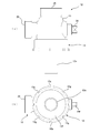
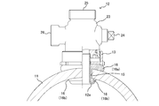
- FIG. 1 is an explanatory view showing a cross section of a water pipe 11 with a gate valve 10 attached thereto.
- the gate valve 10 is attached and fixed to the water pipe 11 as shown in FIG. 1 so that the water faucet can be connected to the water pipe 11 without water interruption.
- the gate valve 10 is for preventing a large amount of water from flowing out of the water pipe 11 in connection with the construction.
- the gate valve 10 is provided in the jig insertion passage 10a of the gate valve 10 in the drilling machine 14 (see FIG. 2).
- the drill portion 14b is advanced and retracted to perforate the peripheral wall of the water pipe 11, or when the water faucet is connected to the water outlet by the water faucet mounting jig A according to the present invention (see FIG. 7), Since it is possible to control the presence or absence of running water from the water outlet while opening and closing the gate valve 10, it is possible to realize the installation work of the water faucet without water interruption.
- the gate valve 10 has a gate valve main body 10b attached to a water pipe 11 by tightening a chain 10c or a wire.
- the gate valve main body 10b is provided with a jig insertion passage 10a in the center, and the jig insertion passage 10a is disposed at a position where a water split port is formed in a drilling process described later.
- the end of the jig insertion passage 10a is placed in a watertight manner on the peripheral wall of the water pipe 11 through the leg tube 10d.
- the base 10e of the gate valve main body 10b is provided with a shutter 10f that opens and closes the jig insertion passage 10a.
- the base of the shutter 10f is advanced and retracted by an opening / closing handle 10g through an advancement / retraction screwing part 10h. It is configured as follows.
- a jig connecting flange 10i for mounting and fixing the water faucet mounting jig A of the present invention is provided.
- the gate valve 10 having the above structure is mounted and fixed to the water pipe 11, and the jig connecting flange 10 i at the upper part thereof is attached to the drill pipe 14.
- the lower end flange 14e is connected and fixed to complete preparation for drilling work on the peripheral wall of the water pipe 11 (see FIG. 2).
- FIG. 2 is an explanatory diagram for explaining a state in which the perforator 14 is attached to the gate valve 10.
- the punching machine 14 is illustrated with the upper mechanism omitted for convenience of explanation.
- the drill shaft 14a of the drilling machine 14 is inserted into the jig insertion passage 10a of the gate valve 10, and the drill portion 14b attached to the tip of the drill shaft 14a is applied to the water outlet forming position on the peripheral wall of the water pipe 11,
- the water diversion opening 15 is drilled by the core drill 14c and the center drill 14d provided in the drill portion 14b.
- the shutter 10f of the gate valve 10 is opened, and the center drill 14d and the core drill 14c are inserted into the jig insertion passage 10a.
- the drill shaft 14a is advanced until the tip of the center drill 14d penetrates the pipe wall of the water pipe 11, and then the core drill 14c is allowed to flow out while cutting the powder while overflowing from a drain port (not shown) provided separately in the gate valve 10.
- the water-dividing port 15 is formed by drilling into a circular shape while bringing the cutting edge into contact with the pipe wall.
- the drill shaft 14a is raised and removed along with the pipe wall from which the drill portion 14b is cut out from the jig insertion passage 10a, and the shutter 10f and the drain port (not shown) of the gate valve 10 are closed. Then, the punching machine 14 is removed from the jig continuous flange 10i of the gate valve 10 to complete the drilling process.
- FIG. 3 is an explanatory view showing an appearance of the water faucet 12 in a state where a cap nut 13 described later is mounted
- FIG. 4 is an explanatory view showing a cross section of the water tap 12.
- the water faucet 12 has an upper water passage 25 provided at the top of the water faucet base 23 and a side water passage 26 provided at the side of the water faucet base 23.
- the water supplied from the side of the metal sleeve 12e provided at the lower part of the water faucet base 23 can be selectively passed to the upper water inlet 25 and the side water outlet 26 by switching the opening and closing shaft 24. It is said.
- the water faucet 12 is provided at the center of the water pipe 12a constituting the part of the water pipe, the water inflow part 12b and the water outflow part 12c before and after that, and the water pipe 12a.
- a substantially spherical valve body 12d which constitutes a ball valve having a water diversion function.
- the valve body 12d is provided in the middle of the water pipe 12a to open and stop the water in the water pipe, and the diversion channel can be opened and closed by operating the opening / closing shaft 24 of the valve body 12d.
- the water faucet 12 is provided at a branch portion for communicating with a water outlet 15 formed in the water pipe 11 to form a branch path.
- the water faucet mounting jig A of the present invention is inserted into a water distribution port integrally with a cylindrical metal sleeve 12e together with a rubber packing 16 described later.
- the metal sleeve 12e is integrally connected to the water pipe of the water faucet 12.
- the rubber sleeve 16e is inserted into and protruded into the water pipe 11 from the water outlet 15 together with the rubber packing 16 fitted on the outer periphery thereof, and the protruding tip
- the water faucet 12 is connected and fixed to the water outlet by bending and caulking the portion with a diameter-enlargement roller that is the main body of the water faucet mounting jig A of the present invention.
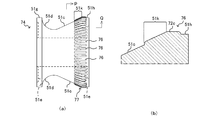
- FIG. 5A shows the appearance of the rubber packing 16
- FIG. 5B shows a cross section of the rubber packing 16.
- the rubber packing 16 is constituted by an upper half flange portion 16a and a lower half cylindrical mounting portion 16b, and the upper half inner peripheral surface and the lower half inner peripheral surface are formed with the metal sleeve 12e.
- a loose allowance 16c and a fit allowance 16d are configured.
- a step taper portion 16e is formed at the inner boundary between the loose allowance 16c and the fit allowance 16d so that the metal sleeve 12e can be smoothly passed through when the metal sleeve 12e is inserted.
- a locking step portion 16f is formed between the flange portion 16a and the mounting portion 16b on the outer side of the rubber packing 16 due to the difference in diameter between the two, and the locking step portion 16f is connected to the peripheral edge of the water diverting port 15. By contacting the vicinity, the rubber packing 16 is prevented from falling into the water pipe 11.
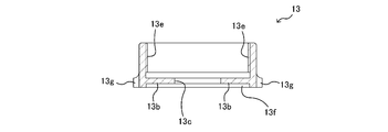
- cap nut configuration Next, the structure of the cap nut 13 illustrated with the water stopper 12 in FIG. 3 will be described with reference to FIGS. 3, 4, and 6.
- the cap nut 13 is screwed into the lower part of the water faucet base 23.
- a male screw is formed on the lower peripheral surface of the water faucet base 23 to form a cap nut screwing portion 23 a for screwing the cap nut 13.
- the cap nut 13 is for compressing with a rubber packing 16 between the water pipe 12 and the outer wall surface of the water pipe 11 when the water tap 12 is attached to the water outlet 15 in a crimped state. It functions as a member for ensuring the water tightness of the water pipe and the fixing of the water faucet 12 to the water pipe 11.
- a sleeve insertion hole 13 c through which the above-described metal sleeve 12 e of the water faucet 12 is inserted is formed in the center of the cap nut 13.
- Reference numeral 13 b denotes a bag surface of the cap nut 13.
- a female screw portion 13e is formed on the inner surface of the cap nut 13 and is screwed with a cap nut screwing portion 23a on the peripheral surface of the water faucet base 23 so that the inner space of the cap nut 13 is above the bag surface 13b. Is a fitting space with the water faucet base 23.
- a concave rubber packing fitting portion 13 f for fitting the flange portion 16 a of the rubber packing 16 is formed on the outer surface of the bag surface 13 b of the bag nut 13.
- channel in the surrounding surface is formed in the lower peripheral wall of the cap nut 13, and the fastener engaging part 13g is the water faucet base body 23 (water faucet 12). This is for engaging the fastener when screwing the cap nut 13.
- the water faucet mounting jig A is naturally removed when the water faucet 12 is continuously connected to the water pipe 11 through the water outlet 15 and the water distribution work is completed.
- a fastener such as a spanner is engaged with the fastener engaging portion 13g of the cap nut 13 and screwed into the lower portion of the water faucet 12.
- the cap nut 13 slides along the axial direction of the rubber packing 16 fitted on the metal sleeve 12e with respect to the water faucet base 23.
- the cap nut 13 since the water faucet 12 is attached in the caulking state to the water outlet 15, if the fastener engaging portion 13g of the cap nut 13 is rotated in the screw release direction with a spanner or the like, the cap nut 13 Is slid toward the water pipe 11 side (that is, in a direction away from the water faucet base 23) at the screwed portion with the lower part of the water tap base 23, and the flange portion 16 a of the rubber packing 16 head is connected to the pipe of the water pipe 11. It compresses between the wall outer surfaces.
- a water faucet mounting jig A used in the water diverter 15 in the vertical direction.
- a water faucet 12 is continuously connected directly above a horizontally installed water pipe 11, and a rubber packing 16 and a metal sleeve 12 e are attached from the vertical direction to a vertical water distribution port 15 on the peripheral wall of the water pipe 11 to be caulked.
- This will be described as a water faucet mounting jig A used in a vertical water faucet mounting structure.
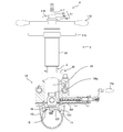
- FIG. 7 is a cross-sectional view showing a state in which the water faucet mounting jig A is placed and fixed on the gate valve 10.
- FIG. 8 is an explanatory view showing the appearance of the water faucet mounting jig A.
- FIG. These are explanatory drawings which showed the cross-sectional structure of the jig A for faucet attachment.
- the water faucet mounting jig A is provided with a handle operating mechanism in which various handles (elevating handle 119 and diameter expanding handle 118) are concentrated on the upper part. Yes. These handle operating mechanisms are provided in the upper elevating body 2.
- the upper elevating body 2 includes a pressing shaft elevating guide 56, a main shaft 111, a diameter expansion operation shaft 58, an integral lock mechanism 27, a pulling nut 117, and a diameter expansion amount detection mechanism 28. It consists of.
- the pressing shaft raising / lowering guide 56 is a substantially cylindrical member having a female screw 56a formed on the inner peripheral surface thereof, and can be screwed to the male screw 3a provided on the outer peripheral surface of the diameter expanding machine main body 3.
- a lower end flange 30 is provided at the lower portion of the diameter expanding machine main body 3, and can be integrally connected to the jig connecting flange 10 i above the gate valve 10 via the lower end flange 30. . Therefore, by rotating the pressing shaft raising / lowering guide 56, the entire upper elevator body 2 is raised and lowered relative to the diameter expanding machine main body 3 attached and fixed to the jig continuous flange 10i.
- the main shaft 111 is suspended in the center in the longitudinal direction of the water faucet mounting jig A, and includes a sleeve push-out pipe 54, an eccentric movable shaft 52 as a roller shaft inserted into the sleeve push-out pipe 54, An eccentric movable bearing 53 for stably supporting the eccentric movable shaft 52 in the sleeve push-out pipe 54 is interposed in a cross-sectional space between the eccentric movable shaft 52 and the sleeve push-out pipe 54 (FIG. 10A). )reference).
- the lower part of the sleeve push-out pipe 54 is formed in a cylindrical shape that is thicker than the upper part of the sleeve push-out pipe 54, and the contact end 54a at the lower end is the upper part of the water faucet 12 (the upper water outlet 25 Edge).
- a diameter expanding head 57 that rotates simultaneously with the rotation of the eccentric movable shaft 52 is connected to the lower end of the eccentric movable shaft 52 inserted into the sleeve push-out pipe 54.
- the rubber packing 16 is detachably mounted together with the water tap 12. At this time, the rubber packing 16 is also fitted to the outer periphery of the metal sleeve 12e portion of the water faucet 12.
- the diameter expansion head 57 is provided with a diameter expansion roller 51 obliquely upward.
- This diameter expansion roller 51 is one of the characteristic structures in the present invention, and will be described in detail later.
- the eccentric movable shaft 52 rotates eccentrically from the center of the main shaft 111, so that the diameter expansion roller 51 obliquely provided on the diameter expansion head 57 is outside the outer diameter of the main shaft 111, that is, the outer diameter of the sleeve extrusion pipe 54. It will be free to appear and disappear.
- the diameter-expanding roller 51 is immersed in the cross-sectional space between the eccentric movable shaft 52 and the sleeve push-out pipe 54, it can be inserted through the water diverting port 15 in that state, and then advance to the tip of the water diverting port 15.
- the diameter-expanding roller 51 is rotated so that it protrudes outward from the cross-sectional space between the eccentric movable shaft 52 and the sleeve push-out pipe 54.
- the diameter expansion roller 51 is displaced to a position where the rubber packing 16 and the metal sleeve 12e positioned around the water diverting port 15 can be caulked.
- the outer peripheral surface of the eccentric movable bearing 53 that contacts the inner peripheral surface of the metal sleeve 12e includes the outer peripheral surface of the eccentric movable bearing 53 and the inner peripheral surface of the metal sleeve 12e.
- a sliding member 90 for preventing seizure due to friction is provided.
- This anti-seizure sliding member 90 is formed of a semi-cylindrical long member, and is attached to the peripheral surface portion of the eccentric movable bearing 53 by bolts 90a.
- the material is made of MC nylon so that the inside of the metal sleeve 12e is smooth. It is slidable.
- handles for operating the sleeve push-out pipe 54, the eccentric movable shaft 52, and the eccentric movable bearing 53 that constitute the main shaft 111 are operated. It is centrally arranged as a mechanism.
- Reference numeral 118 denotes a diameter expansion handle, and 119 denotes a lifting handle.
- a head retracting lever 116 is provided above the diameter expansion handle 118, and a pull-up nut 117 is screwed onto the eccentric movable shaft 52 further above.
- the head retracting lever 116 rotates the eccentric movable shaft 52 eccentrically, and causes the diameter expanding roller 51 obliquely provided on the diameter expanding head 57 to project and retract on the inner and outer sides of the outer diameter of the main shaft 111.
- 27 is disposed in a key connection block 60 constituting the member 27.
- the pull-up nut 117 performs a lifting operation of the eccentric movable shaft 52, mainly a lifting operation of the diameter expanding head 57 that has advanced to the outside of the outer diameter of the main shaft 111, and is a metal projecting into the water pipe 11.
- the distal end opening of the sleeve 12e is deformed while applying a predetermined pressure corresponding to the pulling amount of the pulling nut 117 by a diameter expansion roller 51 obliquely provided on the diameter expansion head 57.
- the diameter expansion handle 118 is for rotating the main shaft 111 in a state where the diameter expansion roller 51 obliquely provided on the diameter expansion head 57 is in contact with the opening of the tip end of the metal sleeve 12e. It is disposed on the diameter-expanding operation shaft 58 that is continuously provided.
- the diameter expansion handle 118 is provided on the diameter expansion operation shaft 58 provided at the upper end of the pressing shaft lifting guide 56 and functions as a handle for rotating the main shaft 111 around the axis.
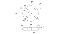
- the integrated lock mechanism 27 is connected to a key block 59 fixed to the upper end surface of the diameter expansion operation shaft 58 and to the upper end surface of the key block 59 so as to be interlocked with each other.
- the key connection block 60 and a washer 61 stacked on the upper surface of the key connection block 60 are configured.
- the key block 59 shown in FIG. 11 is provided with an eccentric movable shaft insertion hole 59a at an eccentric position, and an engagement groove 59b communicating with the eccentric movable shaft insertion hole 59a is formed on the upper surface of the key block 59.
- a bolt hole 59c is provided in the vicinity of the peripheral edge so as to be integrally connected to the lower diameter expanding operation shaft 58.
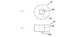
- the key connecting block 60 shown in FIG. 12 has a tenon 60a projecting on the lower surface, and when it is overlapped with the lower key block 59, it engages with the engaging groove 59b of the key block 59 so as to be integrally rotatable. 27 is constructed.
- an H-shaped engagement hole 60b is provided in the center of the key connection block 60, and the eccentric movable shaft 52 that passes therethrough is engaged and rotated integrally at the same time, and the eccentric movable shaft 52 is movable up and down.
- the water faucet mounting jig A configured as described above has a lower end flange 30 provided at the lower end of the cylindrical diameter expanding machine main body 3 as a jig continuous flange 10i of the gate valve 10.
- the gate valve 10 is integrated with the gate valve 10 by being mounted on and fixed to.
- the hollow portion of the diameter expanding machine main body 3 communicates with the jig insertion passage 10 a of the gate valve 10, and the diameter expanding head 57 inserted through the inside of the diameter expanding machine main body 3 is connected to the gate together with the water tap 12 and the rubber packing 16. It passes through the jig insertion passage 10 a of the valve 10 and advances to the water diversion port 15 of the water pipe 11.
- the main shaft 111 is lowered while the contact end 54a of the sleeve push-out pipe 54 and the upper part of the water tap 12 provided with the metal sleeve 12e are brought into contact with each other, and the metal sleeve 12e is rubberized by the sleeve push-out pipe 54.
- the tip opening 12 f of the metal sleeve 12 e passes through the inner periphery of the rubber packing 16 and penetrates into the water pipe 11.
- the diameter expansion head 57 disposed at the lower end of the main shaft 111 is projected further inward than the tip opening 12f of the metal sleeve 12e projecting into the water pipe 11 from the water diversion port 15.
- the diameter expansion head 57 is a state in which the diameter expansion roller 51 obliquely provided on the diameter expansion head 57 is immersed inside the outer diameter of the main shaft 111.
- the eccentric movable shaft 52 is rotated approximately 180 degrees by the head retracting lever 116, and the diameter expansion roller 51 obliquely provided on the diameter expansion head 57 is advanced to the outside of the outer diameter of the main shaft 111. Then, the pull-up nut 117 is operated to bring the diameter expansion roller 51 into contact with the tip opening 12f of the metal sleeve 12e with a predetermined pressure.
- the integral lock mechanism 27 is operated to lock the eccentric movable shaft 52 and the eccentric movable bearing 53 so as to rotate integrally, and the diameter expanding handle 118 is rotated to rotate the eccentric movable shaft 52 and the eccentric movable bearing 53. Rotate together.
- this operation is repeated a predetermined number of times, as shown in FIG. 15, the tip opening 12 f of the metal sleeve 12 e is expanded in diameter so that the metal sleeve 12 e together with the rubber packing 16 is crimped to the water distribution port 15 of the water pipe 11.
- the main shaft 111 is brought into contact with the outer peripheral edge of the tip opening portion 12f of the metal sleeve 12e protruding into the water pipe 11.
- the front end opening 12f of the metal sleeve 12e is bent outwardly.
- the pulling nut 117 is operated to release the pressure applied to the tip opening 12f, the integrated lock mechanism 27 is released, and the head retracting lever 116 is operated to increase the diameter expansion roller 51. Is buried inside the outer diameter of the main shaft 111. Then, the spindle 111 is pulled up by operating the lifting handle 119 of the lifting mechanism, and the shutter 10f of the gate valve 10 is advanced to a position where the jig insertion passage 10a is closed to block the flow of water from the water pipe 11. To do. Further, the opening / closing shaft 24 of the water faucet 12 attached to the water distribution port 15 is operated through a stem opening / closing handle 10j formed in the gate valve 10 to set the water stop state.
- the end opening 12 f of the metal sleeve 12 e is expanded in diameter so that the metal sleeve 12 e is caulked together with the rubber packing 16 at the water distribution port 15 of the water pipe 11. 12 is formed.
- the diameter of the tip opening 12f of the metal sleeve 12e can be increased with a light rotational force. Furthermore, the buckling when the diameter of the tip opening 12f of the metal sleeve 12e is expanded is eliminated, and the accuracy of the diameter expansion can be improved.
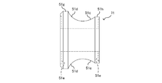
- the diameter-enlarging roller 51 of the present invention has a peripheral surface formed in a drum-shaped recess, and the roller shaft 51a of the diameter-enlarging roller 51 is expanded in diameter.
- a diameter-enlarged roller 51 is obliquely installed in an inclined roller storage chamber 51 b formed in the head 57.
- a substantially upper half is a tapered portion 51c, and a substantially lower half is a rounded portion 51d.
- the substantially upper half is formed on an inclined linear flat surface, and is formed continuously with the end edge to form a rounded portion 51d.
- the oblique inclination angle is an angle ⁇ (a depression angle ⁇ ) formed by a virtual straight line Y orthogonal to the axis X of the eccentric movable shaft 52 (main shaft 111) and the tapered portion 51c.
- the oblique angle of the diameter expansion roller 51 can be adjusted so as to be in the range of 65 degrees to 77 degrees.
- the rounded portion 51d is formed in an R shape that is continuously deep from the linear flat surface of the tapered portion 51c and is formed in a semicircular arc shape, and has a drum shape.
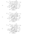
- a peripheral surface shape of the diameter-expanding roller 51 As shown in FIG. 17 (a), when it is brought into contact with the inner peripheral surface of the end edge of the metal sleeve 12e and is pulled up while rotating, first the leading end collar portion is first.
- FIG. 17B the end of the metal sleeve 12e is expanded into a flat trumpet shape along the taper portion 51c, and the end of the metal sleeve 12e in the elastic region of the sleeve tube end with a small diameter expansion force. Widen the edges.
- the sleeve tube end where the rounded portion 51d of the peripheral surface is expanded flat is plasticized into a shape close to an R-shaped true semicircular arc. Deform.
- it is elastically deformed into a flat trumpet-shaped taper shape at the previous stage, it is easy to be plastically deformed into a semi-circular arc shape with a rounded shape at the next stage, and the diameter expansion force is reduced to reduce the tip and top of the metal sleeve 12e. Deformation buckling can be prevented.
- the expansion roller 51 of the water faucet mounting jig A according to the present invention is required.
- the peripheral member described above is formed in a two-stage shape with a tapered portion 51c as a region to be elastically deformed and a rounded portion 51d as a region to be plastically deformed, without applying a large burden to the peripheral members described above. There is an effect that the diameter expansion work can be performed.
- the elastic deformation stress described above is too smaller than the yield stress, for example, if the angle ⁇ exceeds 77 degrees, the acute-side inclination angle of the roller shaft 51a with respect to the axis X becomes small, that is, the diameter expansion roller 51 is This is not preferable because it becomes too close to the vertical, and the stress applied to the terminal flange 51g of the diameter-enlargement roller 51 increases and buckling tends to occur.
- the elastic deformation stress described above is larger than the yield stress, for example, when the angle ⁇ is less than 65 degrees, the acute-side inclination angle of the roller shaft 51a with respect to the axis X becomes large, that is, the diameter expansion roller 51 is horizontal.
- the taper portion 51c has already undergone plastic deformation, and when the diameter expansion is finished, the metal sleeve 12e extending in the vertical direction and the semi-circular arc caulking formed at the tip thereof are formed. A deformed connection portion that expands obliquely is formed between the two portions, which is not preferable.
- the diameter expansion stress at the taper part 51c pushes the diameter expansion roller 51 in the direction of the start end collar part 51h, and the radius part 51d pushes in the direction of the terminal end collar part 51g. That is, the force generated toward the end flange 51g in the axial direction of the roller shaft 51a generated along with the plastic deformation of the metal sleeve 12e in the rounded portion 51d, and the roller generated along with the elastic deformation of the metal sleeve 12e in the tapered portion 51c. Since the difference from the force toward the starting end collar 51h in the axial direction of the shaft 51a becomes the pressure applied to the inner wall of the roller storage chamber 51b, the angle ⁇ of the expansion roller 51 is in the range of 65 to 77 degrees.
- the plastic deformation function can be sufficiently achieved without imparting a large plastic deformation force to the diameter expansion roller 51.
- the frictional force generated between the lower end surface 51j and the roller storage chamber 51b can be reduced as much as possible to avoid excessive wear.
- the semicircular part is formed by the round part 51d without increasing the bending force of the eccentric movable shaft 52 and the eccentric movable bearing 53 (main shaft).
- Arc-shaped round-shaped folds can be formed.
- a concave groove 51e is formed on the upper end surface 51i (starting end surface) and the lower end surface 51j (terminal end surface) of the inclined diameter increasing roller 51, and a shim 51f is fitted. That is, the diameter-enlarging roller 51 is accommodated in the roller accommodating chamber 51b of the diameter-enlarging head 57 in a loosely fitted state, and the upper and lower end surfaces 51i, 51j of the obliquely-increasing diameter expanding roller 51 are accommodated in the obliquely formed roller accommodating chamber 51b. Since it is in close contact with the wall surface, a shim 51f is interposed therebetween so as not to hinder the rotation of the diameter expanding roller 51. Since the shim 51f is accurately fitted into the concave groove 51e, unnecessary detachment or Uneven wear can be prevented.
- Diameter expansion detection mechanism Further, in the water faucet mounting jig A according to the present invention, in order to detect the diameter expansion amount of the tip of the metal sleeve 12e by the diameter expansion roller 51, the diameter expansion amount detection mechanism 28 is provided and the diameter expansion amount detection is performed.
- the mechanism 28 is configured to display the amount of increase and rotation of the eccentric movable shaft 52 as a diameter expansion amount by a scale of the diameter expansion detection nut 55 shown in FIG.
- the diameter expansion amount detection mechanism 28 includes a pull-up nut 117 (see FIG. 18) provided with an upper end recessed portion 117 a on the upper surface of the washer 61, and a pull-up nut as shown in FIG. 19.
- the lower cylindrical portion 55a has an outer diameter that can be inserted into the upper end concave portion 117a of the 117 and has a scale formed on the peripheral surface, and a nut flange 55b formed at the upper end of the lower cylindrical portion 55a.
- the formed diameter expansion amount detection nut 55 and a fixed nut 62 that overlaps the upper surface of the nut flange 55 b of the diameter expansion amount detection nut 55 and is screwed to the eccentric movable shaft 52 are configured.
- the diameter expansion amount detection nut 55 is fixed to the eccentric movable shaft 52 by a fixed nut 62, and when the eccentric movable shaft 52 is pulled up, the lower cylinder of the diameter expansion amount detection nut 55 from the upper end recess 117a of the pull-up nut 117.
- the scale engraved on the portion 55a is gradually exposed.
- This exposure amount indicates the amount by which the eccentric movable shaft 52 is pulled up, that is, the amount by which the sleeve is folded back or the amount of diameter expansion. It is possible to recognize the folded state of the metal sleeve 12e and confirm the attachment and sealing state of the water faucet 12.
- FIG. 21 shows a modification of the diameter expanding roller that can be used in place of the above-described diameter expanding roller 51.
- symbol is attached
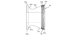
- the diameter-expanding roller 71 has substantially the same configuration as the above-described diameter-expanding roller 51, but the tapered portion 51c is shorter than the diameter-expanding roller 51 and is larger than the diameter of the terminal flange 51g. Also, the configuration is different in that the diameter of the starting end collar 51h is smaller.
- the diameter-expanding roller 71 having such a configuration can also reduce the area of the tapered portion 51c, and the caulking operation for expanding the diameter while reducing the sliding friction generated between the tapered portion 51c and the sleeve inner peripheral surface. It can be performed.
- Friction part Although not necessarily an essential component in the water faucet attachment jig A according to the present embodiment, a friction portion may be formed on the diameter expansion roller in order to perform the diameter expansion work of the sleeve more efficiently.
- the sleeve diameter expansion operation is performed by rotating the eccentric movable shaft 52 to expose the diameter expansion head 57 to the outside of the sleeve, pulling the eccentric movable shaft 52 up and contacting the sleeve with the diameter expansion roller.
- the diameter expansion handle 118 is rotated and the diameter expansion roller is rolled at the end of the sleeve, and the caulking work is performed, but the lifting force of the eccentric movable shaft 52 is strong, and the diameter expansion is performed by the reaction from the sleeve.
- the diameter-expanding roller When a large force is applied to the roller, the diameter-expanding roller is strongly pressed against the wall surface of the roller shaft 51a or the roller storage chamber 51b and may rarely rotate, causing slippage between the sleeve and the diameter-expanding roller. There is a case.
- FIG. 22A is an explanatory view showing a diameter-expanding roller 73 in which a friction portion 72 is formed based on the diameter-expanding roller 71 shown in FIG. 21, and
- FIG. 22B is a diagram of P and Q in FIG. It is a cross-sectional enlarged view in a part.
- the diameter-expanding roller 73 has substantially the same configuration as the diameter-expanding roller 71, but the friction part 72 is formed on the starting end collar 51h located on the upper end side of the recess formed by the tapered portion 51c and the rounded portion 51d. The structure is different.
- the friction portion 72 in the diameter-enlarging roller 73 is formed from the start end flange 51h to the upper region 51k in the vicinity of the start end flange 51h side of the tapered portion 51c.
- the friction portion 72 is not necessarily provided as shown in FIG. 22 (a), and it is sufficient that the sleeve is formed at least on the start end flange portion 51h that first contacts the diameter-expanding roller when the sleeve is expanded. Further, it may be formed up to the tapered portion 51c and the rounded portion 51d including the start end flange portion 51h.
- the friction portion 72 is formed by forming a plurality of grooves 72a as a friction structure at predetermined intervals around the circumference of the diameter expansion roller 73 (starting end flange portion 51h). .
- the friction portion 72 is provided with a mountain-valley structure formed by repetition of a crest portion 72c and a trough portion 72d, as shown in FIG. 22 (b).
- the difference from the portion 72d, that is, the groove depth is formed so as to gradually decrease from the starting end flange portion 51h to the tapered portion 51c.
- the diameter expansion roller 74 is formed by providing the friction portion 72 based on the diameter expansion roller 51 as shown in FIG. Of course, it may be. Further, the concave portion of the diameter expansion roller does not necessarily have both the tapered portion 51c and the rounded portion 51d, and if the sleeve end has a surface that can be formed into a turning shape, the friction portion 72 is formed. Thus, the same effect can be enjoyed.
- the present application provides a water faucet mounting jig comprising a diameter-enlargement roller having a friction portion, which has a surface that can be formed into a turning shape at the end of the sleeve but does not have both the tapered portion 51c and the rounded portion 51d. Is also provided.
- FIG. 24A is an explanatory view showing the configuration of the diameter-expanding roller 75
- FIG. 24B is an enlarged cross-sectional view of P and Q portions in FIG.
- the diameter-expanding roller 75 has substantially the same configuration as the diameter-expanding roller 74, but a protrusion formed by extending a friction structure constituting the friction portion 77 along the upper region 51 k from the starting end collar 51 h.
- the structure is different in that it is a body 76.
- a plurality of the projecting bodies 76 are also formed at predetermined intervals around the circumference of the diameter-enlarging roller 75 (start end flange 51h). Along with the taper portion 51c and the rounded portion 51d (concave portion) from the start end flange portion 51h, the frictional force in the circumferential direction is generated to make the rotation follow-up of the diameter expanding roller 75 in the circumferential direction of the sleeve inner surface steady.
- the sliding resistance with respect to the sleeve can be suppressed as much as possible, and the burden on the diameter expansion roller and the burden on the peripheral members of the diameter expansion roller due to the formation of the friction portion 72 are reduced.
- the frictional portion 77 is formed by repeating the protrusions 76 so that the peak portions 72c, which are the top portions of the protrusions 76, and the valley portions 72d formed between the protrusions 76 are repeated. It has a structure.
- the crest portion 72c of the friction portion 77 is formed at a blunt apex with its tip rounded so that the trace of contact with the friction portion on the sleeve in contact with the friction portion 77 is minimized. .
- the rotational force of the diameter expansion handle can be efficiently transmitted to the diameter expansion roller. Can be reduced, and the life such as wear of members around the expansion roller can be extended.
- the expansion roller is seized and does not rotate, the diameter cannot be expanded unless a large force is applied to the expansion handle, but the force applied to the expansion handle is reduced by eliminating the seizure of the expansion roller. be able to.
Landscapes
- Engineering & Computer Science (AREA)
- General Engineering & Computer Science (AREA)
- Mechanical Engineering (AREA)
- Health & Medical Sciences (AREA)
- Life Sciences & Earth Sciences (AREA)
- Hydrology & Water Resources (AREA)
- Public Health (AREA)
- Water Supply & Treatment (AREA)
- Branch Pipes, Bends, And The Like (AREA)
- Gasket Seals (AREA)
- Domestic Plumbing Installations (AREA)
Abstract
拡径ローラの押圧拡径力を軽減して座屈を生じないようにすることができると共に、拡径ローラの両端面にシムを確実に取付けることができ、更には、金属スリーブの折返し変形量を外部から確認できる分水栓取付用治具を提供する。 拡径ローラは鼓状の凹部に形成し、しかも凹部は斜設した拡径ローラの略上半を略テーパー部に形成すると共に、略下半をアール部に形成した。また、斜設した拡径ローラの傾斜角は65度から77度の範囲内としたことや、拡径ローラの上端面と下端面に凹状溝部を形成し、凹状溝部にシムを嵌着したことにも特徴を有する。
Description
この発明は、水道管の周壁を穿孔して設けた分水口に分水栓を設ける分水栓取付用治具の技術に関する。
従来、工場やオフィス、各家庭などの建屋に水を供給すべく、河川等から取水された水を通水するための水道管が埋設されている。
新たな建屋が新設されると、建屋内の水回り設備に水を供給するために、既設の水道管から分水するための分水栓を該水道管に取付ける工事を行う場合がある。
その場合には、ドリルを備えた穿孔機により水道管の周壁に分水口を穿設し、この分水口の周縁に金属スリーブや同スリーブを一体的に備えた分水栓をゴムパッキンと共に装着することで、分水口からの水漏れを防止しつつ、水道管からの分水を可能とする。
特に近年では、金属製のスリーブや分水栓と一体的に形成されたスリーブ部分(以下、単に金属スリーブともいう。)を分水口に係止固定するにあたり、金属スリーブの一端開口部を水道管の分水口内部から突出させておき、他方、金属スリーブ内を挿嵌した治具の主軸先端に設けた拡径ヘッド及びこれに斜設した拡径ローラ等により水道管内に突出した金属スリーブの開口先端部を外周にめくるように折曲して、水道管の分水口に金属スリーブの開口先端部をカシメ止めする方法が提案されている。
そして、このように水道管と分水栓の取付部分を水密状に行うためには上記したように主軸先端に設けた拡径ヘッド及びこれに斜設した拡径ローラ等より構成した分水栓取付用治具が用いられること知られている。
その治具操作は、例えば特許文献1に記載されているように、主軸を手動により昇降調整しながら主軸先端の拡径ヘッドに斜設した鼓状の拡径ローラを金属スリーブの開口周縁部に当接させ、次いで主軸を回転させて先端の拡径ローラにより金属スリーブの開口周縁部を外側にめくって折曲し、水道管の周壁に穿設した分水口の周縁に金属スリーブの開口周縁部を係合してかしめて分水口に分水栓を係止固定すると共に、分水口のシーリングを確実に行うように構成していた。
そして、水道管の分水口に金属をかしめる構造であるため、水道管の管肉厚が異なったり分水口の大きさが異なってくると、かかる状況の変化に応じて完全なシール機能を果した状態で分水口に分水栓を確実に連通連設しなければならない。そのためには、金属スリーブの拡径端縁部を水道管の分水口に確実に折り曲げてかしめることが必要となる。
ところが、金属スリーブの開口周縁部を主軸の強い回転力で拡径ローラにより折曲すると、時折、拡径ローラによる上方への押し上げ力によって、金属スリーブに蛇腹状の座屈、所謂提灯座屈が生じる場合があった。
このような座屈が発生すると、スリーブの折曲形状がいびつとなり、確実なアールめくり形状とならず、地震などで分水栓の分岐部に不要な曲げ応力や引っ張り応力が発生した場合ゴムパッキンが異常に圧縮されて、水道管と分水栓の分岐部とのシール機能が低下する。
すなわち、水道管の分水口端縁の内側で折り返したスリーブと水道管の内周面との間に介在した筒状のゴムパッキンの折返し端縁部が破損しやすく、シール機能が低下するおそれが生じた。
また、拡径ローラが金属スリーブの開口周縁部を折曲するだけの鼓状であると、ローラの端縁フランジが外側に変形し、拡径ヘッドに形成したローラ収納室内面と端縁フランジが当接し、ローラが回転不可状態となる。
また、ローラのテーパー部だけで金属スリーブを塑性変形すると拡径力が大きくなって拡径ローラの鍔部が傾きシムの摩滅が生じる。また、ローラ端面に所定のスペーサ機能を付与すべくシムを貼着してもシムの正確な接合ができず、正確なスペーサ機能を発揮することができなかった。
更には、断水しないで分岐作業を行うことが必要であるため拡径ローラの作動部分は水密状で外部から視認できない構造となっており、従って、分岐部における金属スリーブの折返し変形量を確認することができなかった。
本発明は、斯かる事情に鑑みてなされたものであって、拡径ローラの押圧拡径力を軽減して座屈を生じないようにすることができると共に、拡径ローラの両端面にシムを確実に取付けることができ、更には、金属スリーブの折返し変形量を外部から確認できる分水栓取付用治具を提供する。
上記従来の課題を解決するために、本発明に係る分水栓取付用治具では、(1)主軸の先端にゴムパッキンを装着して水道管に穿孔した分水口に該ゴムパッキンを嵌合し、前記ゴムパッキンの内周面に遊嵌した金属スリーブの開口先端部を前記水道管内に挿入突出可能に構成し、前記主軸には、長手方向に偏心可動軸を挿管し、該偏心可動軸の下端に拡径ヘッドを介して拡径ローラを斜設し、前記偏心可動軸の偏心回転により前記拡径ローラが前記主軸の外径の内側又は外側に出没自在となるように構成し、前記拡径ローラを前記主軸の外径の外側に進出した状態で、該拡径ローラを水道管内に突出した前記金属スリーブの開口先端部に当接させながら前記主軸の回転により該金属スリーブの開口先端部をゴムパッキンと共に外側にめくり状態で折曲して、前記水道管の分水口に分水栓をカシメ止め可能に構成した分水栓取付用治具において、前記拡径ローラは鼓状の凹部に形成し、しかも凹部は斜設した拡径ローラの略上半を略テーパー部に形成すると共に、略下半をアール部に形成した。
また、本発明に係る分水栓取付用治具では、以下の点にも特徴を有する。
(2)斜設した拡径ローラのテーパー部の傾斜角は、前記偏心可動軸の軸線と直交する仮想直線に対して65度から77度の俯角の範囲内としたこと。
(3)前記拡径ローラは前記凹部の上端側に、前記スリーブの拡径開始時にスリーブ先端が当接する始端鍔部を備え、同始端鍔部には摩擦部が形成されていること。
(4)前記摩擦部は、摩擦力を生起する摩擦構造体が前記始端縁部の周回りに所定間隔で形成されていること。
(5)前記摩擦構造体は、前記始端鍔部からテーパー部の上部領域に至るまで形成されており、同摩擦構造体により形成される前記摩擦部の山谷構造の溝深さが始端鍔部からテーパー部にかけて漸減すること。
(6)前記山谷構造の山部先端は鈍頂であること。
(7)拡径ローラの上端面と下端面に凹状溝部を形成し、凹状溝部にシムを嵌着したこと。
(8)拡径ローラによる金属スリーブ先端の拡径量を検出するために、拡径ローラを先端に連設したローラ軸の基端操作部に、拡径量検出機構を設けると共に、拡径量検出機構はローラ軸の上昇量と回転量を拡径量として拡径量検出ナットの目盛によって表示するように構成したこと。
本発明によれば、拡径ローラの凹部を略上半でテーパー部とし、略下半でアール部としたので、金属スリーブはまずテーパー部で軽く直線的に弾性変形させつつ拡げられて、その後にアール部でアール形状に塑性変形されるので半円弧状の真円をなぞったテーパ形状となり、分水口端縁との係合を確実にしてゴムパッキンのシール機能も充分に果すことができる。
また、拡径ローラシャフトの角度を大にすると終端鍔部に加わる拡径力は大となり、角度を小にすると小さくなるので、必要な拡径力に応じて角度を調整することができる。
テーパー部で金属スリーブの開口先端を塑性変形の直前まで力を加えて弾性変形し、その状態で拡径ローラのアール部で金属スリーブの最終拡径をして塑性変形させつつ折り返すことによりローラ収納室やローラシャフト外周に加わる圧力が少なくなる。従って、分岐口径が大きく、かつ管厚の大きい水道管を用いた分岐作業のように、大きな拡径力を必要とする作業にも適する。
また、ローラシャフトの傾斜調整により拡径力も調整できるため、ローラのテーパー部の傾斜角度を、前記偏心可動軸の軸線と直交する仮想直線に対して65度~77度の俯角の範囲内で調整すると拡径力を小さくできると共に、シャフトとの角度を変えるとローラ収納室内壁に加わるローラの圧力の調整ができる。特に、ローラシャフトの傾斜を大にすると拡径ローラの終端鍔部に加わる力が大となりローラシャフトの傾斜を小にするとローラの終端鍔部に加わる力は小となる。
拡径ローラのテーパー部による拡径力はローラ軸に沿って、金属スリーブの下端部に変形応力をかけるがアール部のような塑性変形する大きな力とはならないので、次工程におけるアール部での塑性変形を確実に、かつ正確にアール状に行うことができる。
また、テーパー部での拡径応力は、拡径ローラを始端鍔部方向に押し、アール部での拡径応力は拡径ローラを終端鍔部方向に押すので、拡径ローラのアール部により生起される塑性変形力からテーパー部により生起される弾性変形力を引いた値がローラ収納室内壁に加わる圧力となり、かかる圧力負荷を小さくすることができる。
このように、ローラ収納室内壁に加わる圧力が小さくなると主軸の外周に加わる力も少なくなる。
このように、拡径ローラのテーパー部による弾性変形力を最大限に使用することにより、ローラ軸及び主軸の曲げ力を小さくすることができ、ローラ軸及び主軸のバランスを良好に取ることができる。
従って、小さな力で拡径作動が行えることになり、シムなどの消耗が少なくなり、拡径ローラの始端鍔部や終端鍔部の変形も生起しない。
また、前記拡径ローラは前記凹部の上端側に、前記スリーブの拡径開始時にスリーブ先端が当接する始端鍔部を備え、同始端鍔部には摩擦部が形成されていることとすれば、スリーブに拡径ローラの拡径力を的確に伝達させることができて滑りが抑制されるため、強制的に拡径ローラを回転させることができ、焼き付きの発生を防止することができる。また、焼き付きが抑制されることにより、金属粉の発生を防止することができる。
また、拡径ハンドルの回転力を効率良く拡径ローラに伝えることができるため、拡径ローラに付与する引上げ方向の力を少なくすることができ、拡径ローラ周辺の部材の摩耗など寿命を延ばすことができる。特に、拡径ローラが焼き付いて回転しない場合、拡径ハンドルに大きな力を加えなければ拡径することができないが、拡径ローラの焼き付きが無くなることにより、拡径ハンドルに付与する力を軽減することができる。
また、スリーブの拡径に伴い溝跡は消えるため、ラッパ状に拡開されたスリーブ内周面をきれいな状態とすることができる。
また、分水栓の口径アップに応用することができる。
更には、ローラ形状を小さくすることができ、拡径ヘッドをコンパクト化することができる。
また、前記摩擦部は、摩擦力を生起する摩擦構造体が前記始端縁部の周回りに所定間隔で形成されていることとすれば、スリーブ内面周方向への拡径ローラの回転追従を堅実なものとしつつも、拡径ローラの凹部に沿ったスリーブの摺動抵抗は可及的抑制でき、摩擦部形成に伴う拡径ローラへの負担や拡径ローラの周辺部材への負担を軽減することができる。
また、前記摩擦構造体は、前記始端鍔部からテーパー部の上部領域に至るまで形成されており、同摩擦構造体により形成される前記摩擦部の山谷構造の溝深さが始端鍔部からテーパー部にかけて漸減することとしたため、摩擦部形成に伴う拡径ローラへの負担や拡径ローラの周辺部材への負担を軽減することができ、また、スリーブの拡開された部分への摩擦部と接触した痕跡を少なくすることができる。
また、前記山谷構造の山部先端は鈍頂であることとすれば、金属粉の発生やスリーブの拡開された部分への摩擦部と接触した痕跡を更に少なくすることができる。
また、拡径ローラの始端面と終端面に凹状の溝を形成してシムを嵌着したので、該ローラを収納する収納室との接触をシムにより緩和して、塑性変形作動をする拡径ローラに偏奇荷重がかかっても収納室との当接負担を可及的に軽減することができる。また、溝によりシムのブレが少なくなり拡径ローラの取付作業が簡便となる。
また、スリーブ管の下端部の折返量、すなわち拡径量を検出可能とすべく、拡径ローラを先端に連設したローラ軸の基端操作部に、拡径量検出機構を設けると共に、拡径量検出機構はローラ軸の上昇と回転量を拡径量としてローラ軸に一体の拡径量検出ナットの目盛によって表示するように構成している。
すなわち、ローラ軸上端部に同ローラ軸の引上を行うための引上ナットを螺合しており、またこの引上ナットの上部内には拡径量検出ナットを目盛部が嵌め合となるように嵌着されており、引上ナットの回転により螺合したローラ軸が上昇すると引上ナット内から拡径量検出ナットの目盛りがその上昇量、すなわちスリーブの折返量や拡径量に応じて露出することとなり、この目盛を読み取ることにより折返量や拡径量を検出可能としている。
特に、拡径ローラの始端鍔部にスリーブ下端を当接した状態を基準点である「0点」としてこのように目盛りを露出させれば、スリーブの拡径量を正確に確認することができる。また、ローラに摩擦部を形成した場合には、ローラが滑ることなく、拡径量を正確に測定することができる。
本発明は、水道水を断水しないで行う分岐工事において、分水口を水道管の外周壁に穿設し、分水口に分水栓を連通連設するための技術に関する。
すなわち、本発明は、例えば老朽化した既設管に更生管を嵌装して二重管とした水道管の周壁にゲートバルブを連通状態に付設固定し、ゲートバルブの流水筒内を進退する穿孔機のドリル本体により二重管よりなる水道管の周壁を穿孔して分水口を形成し、この分水口に断水することなくゲートバルブを介して分水栓を取付けてその後にゲートバルブを除去して、分水口に完全にシーリングをして連通連設するという作業を行うための分水栓取付用治具に関するものであり、特に、係る分水栓の連通連設作業に用いる拡径ローラの形状や傾斜角に工夫を凝らして無用な拡径力を必要とせず、ゴムパッキンによる分水口のシーリングを正確に行えるものである。
すなわち、本発明の特徴は、拡径ローラは鼓状の凹部に形成し、しかも凹部は斜設した拡径ローラの略上半を略テーパー部に形成すると共に、略下半をアール部に形成したことや、斜設した拡径ローラの傾斜角は65度から77度の範囲内としたこと、拡径ローラの上端面(始端面)と下端面(終端面)に凹状溝部を形成し、凹状溝部にシムを嵌着したこと、拡径ローラによる金属スリーブ先端の拡径量を検出するために、拡径ローラを先端に連設したローラ軸の基端操作部に、拡径量検出機構を設けると共に、拡径量検出機構はローラ軸の上昇と回転量を拡径量としてローラ軸に一体の拡径量検出ナットの目盛によって表示するように構成したことである。
以下、図面を参照しながら具体的に実施例を説明する。
[1.水道管へのゲートバルブの取付]
図1は、ゲートバルブ10が取り付けられた状態の水道管11の断面を示す説明図である。
図1は、ゲートバルブ10が取り付けられた状態の水道管11の断面を示す説明図である。
本実施例では、断水せずに水道管11に分水栓を連設する工事が行えるよう、まずは図1に示す如く水道管11にゲートバルブ10を付設固定する。
このゲートバルブ10は、工事に伴って水道管11から大量の水が流出するのを防止するためのものであり、ゲートバルブ10の治具挿通路10a内で穿孔機14(図2参照)のドリル部14bを進退させて水道管11の周壁に穿孔する場合や、本発明に係る分水栓取付用治具A(図7参照)により分水口に分水栓を連通連設する場合に、ゲートバルブ10の開閉を行いながら分水口からの流水の有無を制御することができるため断水することなく分水栓の設置工事を実現することができる。
[2.ゲートバルブ]
ゲートバルブ10は、図1に示すように、ゲートバルブ本体10bを水道管11にチェーン10cやワイヤ等の緊締により装着する。
ゲートバルブ10は、図1に示すように、ゲートバルブ本体10bを水道管11にチェーン10cやワイヤ等の緊締により装着する。
ゲートバルブ本体10bは、中央に治具挿通路10aを設け、この治具挿通路10aは、後述の穿孔処理工程にて分水口を形成する位置に配置される。
治具挿通路10aの終端は、脚筒10dを介して水道管11の周壁に水密状に定置される。
ゲートバルブ本体10bの基盤10eには、治具挿通路10aの開閉を行うシャッター10fが進退自在に設けられており、シャッター10fの基部は開閉ハンドル10gにより進退螺合部10hを介して進退作動するように構成されている。
ゲートバルブ本体10bの上部には、本発明の分水栓取付用治具Aを載置固定するための治具連設フランジ10iが設けられている。
従って、分水栓を水道管11に連通連設する作業に際しては、まず、上記構造のゲートバルブ10を水道管11に装着固定し、その上部の治具連設フランジ10iに、穿孔機14の下端フランジ14eを連設固定して水道管11の周壁への穿孔作業の準備を完了する(図2参照)。
[3.穿孔処理工程]
図2は、穿孔機14をゲートバルブ10に取り付けた状態を説明する説明図である。なお、図2中において穿孔機14は、説明の便宜上、上部機構を省略して記載している。
図2は、穿孔機14をゲートバルブ10に取り付けた状態を説明する説明図である。なお、図2中において穿孔機14は、説明の便宜上、上部機構を省略して記載している。
ゲートバルブ10の治具挿通路10a中に穿孔機14のドリル軸14aを挿入し、同ドリル軸14aの先端に取り付けたドリル部14bを水道管11の周壁の分水口形成位置に当てがい、同ドリル部14bに備えられたコアードリル14cとセンタードリル14dとにより分水口15を穿孔する。
使用に際しては、ゲートバルブ10のシャッター10fを開き、センタードリル14d及びコアードリル14cを治具挿通路10a内へ進入させる。
そして、センタードリル14dの先端が水道管11の管壁を貫通するまでドリル軸14aを進入させ、次いで、ゲートバルブ10に別途設けた図示しない排水口より溢水させながら切削粉を流出させつつコアードリル14cの切っ先を管壁に接触させつつ円状に切削して穿孔し分水口15を形成する。
穿孔が終了した後には、ドリル軸14aを上昇させて治具挿通路10a内からドリル部14bを切り抜いた管壁と共に抜去し、ゲートバルブ10のシャッター10f及び排水口(図示せず)を閉める。そして、穿孔機14をゲートバルブ10の治具連設フランジ10iから取り外し、穿孔処理工程を完了させる。
[4.分水栓の構成]
次に、図3及び図4を参照しつつ、分水栓及びその周辺部品の構造について説明する。図3は後述の袋ナット13を装着した状態の分水栓12の外観を示す説明図であり、図4は分水栓12の断面を示す説明図である。
次に、図3及び図4を参照しつつ、分水栓及びその周辺部品の構造について説明する。図3は後述の袋ナット13を装着した状態の分水栓12の外観を示す説明図であり、図4は分水栓12の断面を示す説明図である。
図3に示すように分水栓12は、分水栓基体23の上部に備えられた上部通水口25及び分水栓基体23の側部に備えられた側部通水口26を有しており、分水栓基体23の下部に備えられた金属スリーブ12e側より供給される水を、開閉軸24の切替を行うことによって、上部通水口25や側部通水口26に選択的に通水可能としている。
また、図4からも分かるように、分水栓12は、流水管路の一部を構成する流水筒12aとその前後の水流入部12b及び水流出部12c、並びに流水筒12aの中央に設けた略球状の弁体12dとより構成されており、分水機能を具備したボールバルブを構成している。すなわち、流水管路内の水を開放・止水するために流水筒12aの中途に弁体12dを介設し弁体12dの開閉軸24の操作により分水路の開閉作業が行えるように構成される。
付言すれば、分水栓12は、水道管11に穿設された分水口15に連通連設して分岐路を構成するための分岐部分に介設されるものである。
追って詳説するが、本発明の分水栓取付用治具Aは、後述するゴムパッキン16と共に筒状の金属スリーブ12eを一体として分水口に挿貫する。
すなわち、金属スリーブ12eは分水栓12の流水管路に一体に連設されており、その外周に嵌着したゴムパッキン16と共に分水口15から水道管11内に挿貫突出し、その突出した先端部分を本発明の分水栓取付用治具Aの主体となる拡径ローラにより折曲してカシメることにより分水栓12を分水口に連設固定するものである。
[5.ゴムパッキンの構成]
次に、分水栓12に形成されている金属スリーブ12eと共に分水口15に装着されるゴムパッキン16の構成について図5を参照して説明する。図5(a)はゴムパッキン16の外観を示しており、図5(b)はゴムパッキン16の断面を示している。
次に、分水栓12に形成されている金属スリーブ12eと共に分水口15に装着されるゴムパッキン16の構成について図5を参照して説明する。図5(a)はゴムパッキン16の外観を示しており、図5(b)はゴムパッキン16の断面を示している。
図5に示すように、ゴムパッキン16は、上半分のフランジ部16aと下半分の筒状の装着部16bとにより構成され、上半部内周面及び下半部内周面は金属スリーブ12eとの遊嵌代16c及び嵌着代16dを構成している。また、遊嵌代16cと嵌着代16dとの内部境界には、金属スリーブ12eを挿入させた際に同境界部分を円滑に通過させるための段差テーパ部16eを形成している。
また、ゴムパッキン16の外側におけるフランジ部16aと装着部16bとの間には、両者の径の差によって係止段差部16fが形成されており、この係止段差部16fを分水口15の周縁近傍に当接させることで、ゴムパッキン16の水道管11内部への落ち込みが防止される。
[6.袋ナットの構成]
次に、図3において分水栓12と共に図示した袋ナット13の構成について、図3、図4、及び図6を参照しつつ説明する。
次に、図3において分水栓12と共に図示した袋ナット13の構成について、図3、図4、及び図6を参照しつつ説明する。
図3において示したように、分水栓基体23の下部には、袋ナット13が螺合される。具体的には、図4に示すように、分水栓基体23の下部周面に雄ネジが形成されており、袋ナット13を螺合させるための袋ナット螺合部23aとしている。
袋ナット13は、分水栓12を分水口15にカシメ状態で取り付ける際に水道管11の管壁外面との間にゴムパッキン16を介在して圧縮するためのものであり、分水口15周縁の水密性や、水道管11に対する分水栓12の固定を堅実なものとするための部材として機能する。
具体的には図6に示すように、袋ナット13の中央には、前述した分水栓12の金属スリーブ12eを挿通させるスリーブ挿通孔13cが穿設されている。なお、13bは袋ナット13の袋面を示す。
袋ナット13の内面には雌ネジ部13eを形成して分水栓基体23の周面の袋ナット螺合部23aと螺合することにより袋ナット13の内方で袋面13bよりも上方空間を分水栓基体23との嵌合空間としている。
袋ナット13の袋面13b外側面にはゴムパッキン16のフランジ部16aを嵌合するための凹状のゴムパッキン嵌着部13fを形成している。
また、袋ナット13の下部周壁には周面に係合溝を形成した締結具係合部13gを形成しており、締結具係合部13gは分水栓基体23(分水栓12)と袋ナット13とを螺合する際に締結具を係合するためのものである。
従って、後述するように水道管11に分水口15を介して分水栓12を連通連設して分水工事が完了すると当然に分水栓取付用治具Aを除去することになるが、この時点でゴムパッキン16による分水栓12のシーリングを確実にするために袋ナット13の締結具係合部13gに締結具、例えばスパナ等を係合して分水栓12下部に螺合した袋ナット13を回転させると、袋ナット13は分水栓基体23に対し金属スリーブ12eに外嵌したゴムパッキン16の軸線方向に沿って摺動する。
従って、前述の通り分水栓12が分水口15にカシメ状態で取り付けられた状態であるため袋ナット13の締結具係合部13gをスパナ等で螺合解除方向へ回転操作すると、袋ナット13は分水栓基体23下部との螺合部分において水道管11側(すなわち、分水栓基体23から離れる方向)へ摺動していきゴムパッキン16頭部のフランジ部16aを水道管11の管壁外面との間で圧縮することとなる。
[7.分水栓取付用治具]
次に、本実施例に係る分水栓取付用治具Aについて、図7~図10を参照して説明する。なお、以下は縦方向の分水口15において使用する治具として説明する。すなわち、水平設置の水道管11の直上に分水栓12を連通連設し、水道管11周壁の縦方向の分水口15に対して縦方向からゴムパッキン16と金属スリーブ12eを装着してカシメるという縦方向の分水栓取付構造において用いる分水栓取付用治具Aとして説明する。
次に、本実施例に係る分水栓取付用治具Aについて、図7~図10を参照して説明する。なお、以下は縦方向の分水口15において使用する治具として説明する。すなわち、水平設置の水道管11の直上に分水栓12を連通連設し、水道管11周壁の縦方向の分水口15に対して縦方向からゴムパッキン16と金属スリーブ12eを装着してカシメるという縦方向の分水栓取付構造において用いる分水栓取付用治具Aとして説明する。
図7は、分水栓取付用治具Aをゲートバルブ10に載置固定した状態を示す断面図であり、図8は分水栓取付用治具Aの外観を示した説明図、図9は分水栓取付用治具Aの断面構造を示した説明図である。
図7及び図8に示すように、本実施例に係る分水栓取付用治具Aは、上部に各種ハンドル(昇降ハンドル119、拡径ハンドル118)を集中したハンドル操作機構が配設されている。これらのハンドル操作機構は上部昇降体2に設けられている。
上部昇降体2は、図9に示すように、押圧軸昇降ガイド56と、主軸111と、拡径操作軸58と、一体ロック機構27と、引上ナット117と、拡径量検出機構28とで構成している。
押圧軸昇降ガイド56は、内周面に雌ネジ56aが形成された略筒状の部材であり、拡径機本体3の外周面に設けた雄ネジ3aと螺合可能としている。拡径機本体3の下部には、図8に示すように下端フランジ30を設けており、同下端フランジ30を介してゲートバルブ10上部の治具連設フランジ10iに一体に連設可能としている。従って、押圧軸昇降ガイド56を回動させることにより、治具連設フランジ10iに取付固定された拡径機本体3に対し、上部昇降体2全体が昇降する。
主軸111は、分水栓取付用治具Aの長手方向の中央に垂設されており、スリーブ押出パイプ54と、スリーブ押出パイプ54の内部に挿貫したローラ軸としての偏心可動軸52と、偏心可動軸52とスリーブ押出パイプ54との間の断面空間に介在して偏心可動軸52をスリーブ押出パイプ54中に安定支持するための偏心可動軸受53とにより構成している(図10(a)参照)。
スリーブ押出パイプ54の下部は、図9に示すように、スリーブ押出パイプ54の上部よりも肉厚の筒状に形成され、下端の接触端54aは分水栓12の上部(上部通水口25の縁部)と当接するように構成されている。
スリーブ押出パイプ54に挿管された偏心可動軸52の下端には偏心可動軸52の回動により同時に回動する拡径ヘッド57が連設され、拡径ヘッド57の下部周面凹部57aには、図7に示したようにゴムパッキン16が分水栓12と共に離脱自在に装着される。なおこのとき、ゴムパッキン16は分水栓12の金属スリーブ12e部分の外周にも嵌着された状態となっている。
また、拡径ヘッド57には、斜め上方に向けて拡径ローラ51が斜設されている。この拡径ローラ51は、本発明において特徴的な構成の一つであり、後に詳述する。
偏心可動軸52は、主軸111の中心から偏心して回転することにより、拡径ヘッド57に斜設された拡径ローラ51は主軸111の外径、すなわち、スリーブ押出パイプ54の外径の内外側に出没自在となる。
すなわち、偏心可動軸52とスリーブ押出パイプ54との間の断面空間に拡径ローラ51が没入すれば、その状態で分水口15中を挿貫することができ、その後分水口15の先方に進出し拡径ローラ51を回動して偏心可動軸52とスリーブ押出パイプ54との間の断面空間から外方にはみ出した状態とする。
このようにして、拡径ローラ51が分水口15の周辺に位置したゴムパッキン16と金属スリーブ12eをカシメることのできる位置に変位する。
金属スリーブ12eの内周面と当接する偏心可動軸受53の外周面には、図10(a)~(d)に示すように、偏心可動軸受53の外周面と該金属スリーブ12eの内周面との摩擦による焼付きを防止するための摺動部材90が設けられている。この焼付き防止の摺動部材90はかまぼこ状の長手部材により形成され、偏心可動軸受53の周面部分にボルト90aによって取付けられており、素材をMCナイロンで構成し金属スリーブ12e内を円滑に摺動可能にしている。
また図9に示すように、分水栓取付用治具Aの上部には、主軸111を構成するスリーブ押出パイプ54や偏心可動軸52、偏心可動軸受53をそれぞれ操作するためのハンドルがハンドル操作機構として集中して配設されている。118は拡径ハンドル、119は昇降ハンドルである。また、拡径ハンドル118の上方には、ヘッド出没レバー116が備えられており、更に上方には引上ナット117が偏心可動軸52に螺着されている。
ヘッド出没レバー116は、偏心可動軸52を偏心回転させて、拡径ヘッド57に斜設された拡径ローラ51を主軸111の外径の内外側に出没させるものであり、後述の一体ロック機構27を構成するキー連結ブロック60に配設されている。
また、引上ナット117は、偏心可動軸52の引き上げ動作、主に主軸111の外径の外側に進出した拡径ヘッド57の引き上げ動作を行うものであり、水道管11内に突出させた金属スリーブ12eの先端開口部を、拡径ヘッド57に斜設された拡径ローラ51で引上ナット117の引上量に応じた所定の圧力を加えつつ変形させるものである。
拡径ハンドル118は、拡径ヘッド57に斜設された拡径ローラ51を金属スリーブ12eの先端開口部へ当接させた状態で主軸111を回転させるためのものであり、主軸111の上部に連設した拡径操作軸58に配設されている。
この拡径ハンドル118により主軸111の回転動作を行いつつ、前述の引上ナット117による偏心可動軸52の引上力を金属スリーブ12eの端部に付与することにより、金属スリーブ12eの開口先端部が外側にめくり状態で折曲される。すなわち、拡径ハンドル118は、押圧軸昇降ガイド56の上端に設けた拡径操作軸58に設けられており、主軸111を軸回りに回転させるためのハンドルとして機能する。
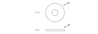
一体ロック機構27は、図9、図11~図13に示すように、拡径操作軸58の上端面に固設したキーブロック59と、該キーブロック59の上端面に連動自在に連設したキー連結ブロック60と、該キー連結ブロック60の上面に重ねたワッシャ61とで構成している。
しかも、図11に示すキーブロック59は偏心した位置に偏心可動軸挿貫孔59aを設け、キーブロック59の上面には、該偏心可動軸挿貫孔59aに連通した係合溝59bを刻設しており、周縁近傍には下方の拡径操作軸58と一体に連結するためのボルト孔59cを設けている。
また、図12に示すキー連結ブロック60は下面にほぞ60aを突設し、下方のキーブロック59と重ねた場合キーブロック59の係合溝59bと係合して一体回転可能となる一体ロック機構27を構成する。また、キー連結ブロック60の中央にはH型の係合孔60bを設け、貫通する偏心可動軸52が係合して同時に一体回転すると共に、偏心可動軸52は上下昇降自在としている。
このように構成した分水栓取付用治具Aは、図7に示したように、筒状の拡径機本体3の下端に設けた下端フランジ30をゲートバルブ10の治具連設フランジ10iに載置固定することによりゲートバルブ10と一体に連設されている。
この際、拡径機本体3の中空部はゲートバルブ10の治具挿通路10aと連通し、拡径機本体3の内部を挿通する拡径ヘッド57が分水栓12やゴムパッキン16と共にゲートバルブ10の治具挿通路10aを通過して水道管11の分水口15へ進出する。
[8.分水栓形成の工程]
図14に示すように、主軸111の下端のゴムパッキン16は上述した昇降機構の降下作動により下方の分水口15に移動する。
図14に示すように、主軸111の下端のゴムパッキン16は上述した昇降機構の降下作動により下方の分水口15に移動する。
そして、スリーブ押出パイプ54の接触端54aによりゴムパッキン16のフランジ部16aを分水口15の周壁面に当接させた後、さらにフランジ部16aを圧縮するように押し込むことにより、ゴムパッキン16の装着部16bが分水口15内に挿入される。
そして、さらに、スリーブ押出パイプ54の接触端54aと金属スリーブ12eを備えた分水栓12の上部とを当接させた状態で、主軸111を降下させてスリーブ押出パイプ54により金属スリーブ12eをゴムパッキン16内に押し込むと金属スリーブ12eの先端開口部12fがゴムパッキン16の内周を通って水道管11内部にまで突き抜ける。
このとき、主軸111の下端に配された拡径ヘッド57は、分水口15から水道管11の内部に突出した金属スリーブ12eの先端開口部12fよりもさらに内方に突出した状態になる。この状態では、拡径ヘッド57は、同拡径ヘッド57に斜設した拡径ローラ51が主軸111の外径の内側に没入した状態である。
続いて、偏心可動軸52をヘッド出没レバー116により略180度回転させて、拡径ヘッド57に斜設した拡径ローラ51を主軸111の外径の外側に進出させる。そして、引上ナット117を操作して、拡径ローラ51を金属スリーブ12eの先端開口部12fに所定の圧力で当接させる。
さらに、一体ロック機構27を操作して偏心可動軸52と偏心可動軸受53とが一体で回転するようにロックし、拡径ハンドル118を回転操作して偏心可動軸52と偏心可動軸受53とを一体に回転させる。この操作を所定回数繰り返すと、図15に示すように、金属スリーブ12eの先端開口部12fが裾広がりに拡径し、ゴムパッキン16と共に金属スリーブ12eが水道管11の分水口15にカシメ止めされる。すなわち、拡径ローラ51を主軸111の外径の外側に進出した状態で、拡径ローラ51を水道管11内に突出した金属スリーブ12eの先端開口部12fの外周縁に当接しながら主軸111を回転させることにより金属スリーブ12eの先端開口部12fを外側にめくり状態で折曲する。
拡径作業が終了すると、引上ナット117を操作して先端開口部12fに付与していた圧力を開放し、一体ロック機構27を解除した上でヘッド出没レバー116を操作して拡径ローラ51を主軸111の外径の内側に埋没させる。そして、昇降機構の昇降ハンドル119を操作して主軸111の引き上げを行い、ゲートバルブ10のシャッター10fが治具挿通路10aを閉塞する位置まで進出させて、水道管11からの水の流通を遮断する。また、ゲートバルブ10に形成したステム開閉ハンドル10jを介して分水口15に取り付けた分水栓12の開閉軸24を操作して止水状態とする。
最後に、ゲートバルブ10の治具連設フランジ10iに取り付けられた分水栓取付用治具Aを取外し、ゲートバルブ10自体も水道管11から取外した後に、袋ナット13の締結具係合部13gに締結具を係合させ、袋ナット13でゴムパッキン16を更に圧縮させて分水栓12の形成作業が終了する。
すなわち、図16に示すように、金属スリーブ12eの先端開口部12fが裾広がりに拡径し、ゴムパッキン16と共に水道管11の分水口15に金属スリーブ12eが一体にカシメ止めされた分水栓12が形成された状態となる。
[9.拡径ローラの構成]
次に、本発明の特徴的な技術である拡径ローラ51の構成について、図10及び図17を参照して説明する。
次に、本発明の特徴的な技術である拡径ローラ51の構成について、図10及び図17を参照して説明する。
上述してきた本実施例の拡径ローラ51によれば、軽い回転力で金属スリーブ12eの先端開口部12fを拡径することができる。さらに、金属スリーブ12eの先端開口部12fを拡径するときの座屈がなくなり拡径量の精度の向上を図ることができる。
本発明の拡径ローラ51は、図10(b)~図10(d)に示すように、周面を鼓状の凹部に形成しており、拡径ローラ51のローラシャフト51aが、拡径ヘッド57に形成した傾斜状のローラ収納室51bに架設され、拡径ローラ51を斜設している。
また、斜設した拡径ローラ51の周面凹部は略上半をテーパー部51cとし、略下半をアール部51dとしている。従って、略上半は傾斜状の直線的平坦面に形成し、その端縁に連設してアール部51dを形成している。しかも、斜設の傾斜角は、図10(b)に示すように、偏心可動軸52(主軸111)の軸線Xと直交する仮想直線Yとテーパー部51cとのなす角度α(俯角α)が65度から77度の範囲内となるように拡径ローラ51の斜設角度を調整することができるように構成している。
アール部51dはテーパー部51cの直線的平坦面から連続して深く半円弧状にえぐったR形状に形成しており、鼓状の変形としている。かかる拡径ローラ51の周面形状とすることにより、図17(a)に示すように金属スリーブ12eの端縁内周面に当接して回転しながら引上げていくと、まず先に始端鍔部51hに当接し、図17(b)に示すようにテーパー部51cに沿って金属スリーブ12e端縁を平坦ラッパ状に拡開して小さな拡径力でスリーブ管端の弾性域において金属スリーブ12e端縁を拡開する。
次いで更に拡径ローラ51を引上げながら回転させると、図17(c)に示すように、周面のアール部51dが平坦に拡開したスリーブ管端をR状の真半円弧に近い形状に塑性変形する。特に前段階で平坦ラッパ状のテーパー形状に弾性変形させているので、次段階でアール形状をつけた半真円弧状に塑性変形しやすく拡径力を少くして金属スリーブ12eの先端や上部の変形座屈を防止することができる。
このように、拡径ローラ51のアール部51dで最終拡径をして折り返す際に、ローラ収納室51bやローラシャフト51aに無用の負荷をかけることがなくなる。
特に水道管11の肉厚や分岐口径の分水口15が大きい場合は、必然的に大きな拡径力を必要とするが、本発明に係る分水栓取付用治具Aの拡径ローラ51のように拡径ローラ51の周面形状を弾性変形させる領域としてのテーパー部51cと塑性変形させる領域としてのアール部51dとの二段階形状とすることにより上記した周辺部材に大きな負担をかけずに折り返し拡径作業が可能となる効果を有する。
更には、前述した角度αを65度から77度の範囲で調整保持すると、小さい拡径力で所望の折り返し、特に半真円弧のR形状の折り曲げができる。すなわち、テーパー部51cにおいて降伏応力に満たないが降伏応力にできるだけ近い弾性変形応力を付与して金属スリーブ12eを弾性変形領域でできるだけ大きく変形させつつ、アール部51dにおいて降伏点を超えるためにテーパー部51cにおいて付与した弾性変形応力では足りなかった分の応力を塑性変形応力として加えることで、焼き付きや極度の摩耗を抑制しつつ堅実なカシメ作業を行うことができる。なお、前述の弾性変形応力が降伏応力よりも小さすぎる場合、例えば角度αが77度を上回る場合は、軸線Xに対するローラシャフト51aの鋭角側傾斜角度が小さくなってしまい、すなわち拡径ローラ51が垂直に近づきすぎてしまい、拡径ローラ51の終端鍔部51gに負荷する応力は増大し、座屈が生じやすくなってしまうため好ましくない。また、前述の弾性変形応力が降伏応力よりも大きい場合、例えば角度αが65度を下回る場合は、軸線Xに対するローラシャフト51aの鋭角側傾斜角度が大きくなってしまい、すなわち拡径ローラ51が水平に近づきすぎてしまい、テーパー部51cにおいて既に塑性変形が行われることとなり、拡径を終了した際に、垂直方向に伸延する金属スリーブ12eの幹部分とその先端に形成した半真円弧状のカシメ部分との間に斜めに拡開する変形接続部分が形成されてしまうこととなり好ましくない。
更には、テーパー部51cでの拡径応力は、拡径ローラ51を始端鍔部51h方向に押し、アール部51dは終端鍔部51g方向に押すことになる。すなわち、アール部51dにおいて金属スリーブ12eの塑性変形に伴って生起するローラシャフト51aの軸線方向で終端鍔部51g側への力と、テーパー部51cにおいて金属スリーブ12eの弾性変形に伴って生起するローラシャフト51aの軸線方向で始端鍔部51h側への力との差がローラ収納室51bの内壁に加わる圧力となるため、拡径ローラ51の傾斜を角度αが65度から77度の範囲となるように調整すると拡径ローラ51に大きな塑性変形力を付与とすることなしに、塑性変形機能を充分に果すことができる。また特に、下端面51jとローラ収納室51bとの間に発生する摩擦力を可及的軽減して極度の減摩を回避することができる。
このようにテーパー部51cによって金属スリーブ12eの端縁の弾性力を最大限に使用すると、偏心可動軸52及び偏心可動軸受53(主軸)の曲げ力を大きくすることなくアール部51dによって真半円弧状のアール状の折り返しを形成することができる。
また、斜設した拡径ローラ51の上端面51i(始端面)と下端面51j(終端面)には凹状溝部51eを刻設し、シム51fを嵌着している。すなわち、拡径ローラ51は拡径ヘッド57のローラ収納室51bに遊嵌状態で収納されており、斜設した拡径ローラ51の上下端面51i,51jは斜めに形成したローラ収納室51bの収壁面と密着した状態となるため、その間にシム51fを介在して拡径ローラ51の回転に支障のないようにしており、シム51fは凹状溝部51eに正確に嵌着されるので不要な離脱や偏奇摩耗を防止することができる。
[10.拡径量検出機構]
また、本発明に係る分水栓取付用治具Aでは、拡径ローラ51による金属スリーブ12eの先端の拡径量を検出するために、拡径量検出機構28を設けると共に、拡径量検出機構28は偏心可動軸52の上昇量と回転量を拡径量として図19にて示す拡径量検出ナット55の目盛によって表示するように構成している。
また、本発明に係る分水栓取付用治具Aでは、拡径ローラ51による金属スリーブ12eの先端の拡径量を検出するために、拡径量検出機構28を設けると共に、拡径量検出機構28は偏心可動軸52の上昇量と回転量を拡径量として図19にて示す拡径量検出ナット55の目盛によって表示するように構成している。
拡径量検出機構28は、図9にて示したように、ワッシャ61の上面に重ね上端凹部117aを備えた引上ナット117(図18参照)と、図19に示すように該引上ナット117の上端凹部117aに挿入可能な外径を有し周面に目盛が刻設された下筒部55aと下筒部55aの上端に形成したナットフランジ55bとよりなり内周面に雌ネジが形成された拡径量検出ナット55と、図20に示すように拡径量検出ナット55のナットフランジ55b上面に重ねて偏心可動軸52に螺合させる固定ナット62とより構成している。
そして、金属スリーブ12eの先端のカシメ作業を行うにあたり、偏心可動軸52を引き上げるために同偏心可動軸52に螺合させている引上ナット117を回動操作すると、引上ナット117は下方へ移動しようとするが、一体ロック機構27を構成するワッシャ61に当接するため位置は変わらず、偏心可動軸52のみが上方へ移動する。
拡径量検出ナット55は固定ナット62により偏心可動軸52に固定されており、偏心可動軸52の引き上げが行われると、引上ナット117の上端凹部117aから拡径量検出ナット55の下筒部55aに刻設された目盛が徐々に露出する。
この露出量は、偏心可動軸52の引き上げ量、すなわち、スリーブの折返量や拡径量を示すこととなるため、内部を透視することができない拡径機本体3において拡径量を検出して金属スリーブ12eの折り返し状態を認知し、分水栓12の取付け及びシール状態を確認することが可能となる。
[11.拡径ローラの変形例]
前述の拡径ローラ51に代えて使用可能な拡径ローラの変形例を図21示す。なお、前述と同様の構成については、同じ符号を付して説明を省略する。
前述の拡径ローラ51に代えて使用可能な拡径ローラの変形例を図21示す。なお、前述と同様の構成については、同じ符号を付して説明を省略する。
図21に示すように拡径ローラ71は、前述の拡径ローラ51と略同様の構成を備えているが、拡径ローラ51に比してテーパー部51cが短く、終端鍔部51gの直径よりも始端鍔部51hの直径の方が小さい点で構成を異にしている。
このような構成を備える拡径ローラ71によっても、テーパー部51cの面積を狭くすることができ、テーパー部51cとスリーブ内周面との間で発生する摺動摩擦を低減しつつ拡径のカシメ作業を行うことができる。
[12.摩擦部]
本実施形態に係る分水栓取付用治具Aにおいて必須の構成ではないものの、スリーブの拡径作業をより効率的に行うべく、拡径ローラに摩擦部を形成しても良い。
本実施形態に係る分水栓取付用治具Aにおいて必須の構成ではないものの、スリーブの拡径作業をより効率的に行うべく、拡径ローラに摩擦部を形成しても良い。
前述したようにスリーブの拡径作業は、偏心可動軸52を回転させて拡径ヘッド57をスリーブの外方へ露出させ、偏心可動軸52を引き上げて拡径ローラにスリーブを当接し、スリーブを変形させた状態で拡径ハンドル118を回転させつつスリーブ端部で拡径ローラを転動させながらカシメ作業を行うのであるが、偏心可動軸52の引上力が強くスリーブからの反作用により拡径ローラに大きな力が働くと、拡径ローラがローラシャフト51aやローラ収納室51bの壁面に強く押し付けられて希に回転しなくなることがあり、スリーブと拡径ローラとの間で滑りが生じてしまう場合がある。
このような状態となると、拡径ローラとスリーブの拡径面との間に焼き付きが発生してしまい、拡径ハンドル118の回転抵抗が大きくなるばかりでなく、焼き付き箇所から金属粉が剥落し、不断水施工の場合は配管中を流れる水に混入してしまうおそれも考えられる。
そこで、これらの事情に鑑みて本発明者らが鋭意研究した結果、拡径ローラに摩擦部を形成することで、このような問題を解消できることが見出された。
図22(a)は図21に示した拡径ローラ71をベースに摩擦部72を形成した拡径ローラ73を示す説明図であり、図22(b)は図22(a)のP及びQ部分における断面拡大図である。
拡径ローラ73は、拡径ローラ71と略同様の構成を備えているが、テーパー部51c及びアール部51dにより形成された凹部の上端側に位置する始端鍔部51hに摩擦部72が形成されている点で構造を異にしている。
より具体的には、拡径ローラ73のおける摩擦部72は、始端鍔部51hからテーパー部51cの始端鍔部51h側近傍である上部領域51kにかけて形成されている。なお摩擦部72は、必ずしも図22(a)に示すように設ける必要はなく、スリーブの拡開時にスリーブが最初に拡径ローラに接触する始端鍔部51hに少なくとも形成されていれば良く、また、始端鍔部51hも含めテーパー部51cやアール部51dに至るまで形成されていても良い。
摩擦部72は、図22(a)に示すように、摩擦構造体としての溝72aを拡径ローラ73(始端鍔部51h)の周回りに所定間隔で複数刻設することで形成している。
したがって、スリーブ拡径の際に、スリーブとの間で主に拡径ローラ73の周回り方向への摩擦力を生起してスリーブ内面周方向への拡径ローラの回転追従を堅実なものとしつつも、始端鍔部51hからテーパー部51c、アール部51d(凹部)に沿ったスリーブに対する摺動抵抗は可及的抑制でき、摩擦部72の形成に伴う拡径ローラへの負担や拡径ローラの周辺部材への負担を軽減することができる。
また摩擦部72は、この溝72aが刻設されることにより、図22(b)に示すように、山部72cと谷部72dの繰り返しよりなる山谷構造を備えており、山部72cと谷部72dとの差、すなわち溝深さが始端鍔部51hからテーパー部51cにかけて漸減するように形成している。
したがって、摩擦部形成に伴う拡径ローラへの負担や拡径ローラの周辺部材への負担を軽減することができ、また、スリーブの拡開された部分への摩擦部と接触した痕跡を少なくすることができる。
なお本項では、拡径ローラ71をベースに摩擦部72を設けた例について説明したが、図23に示すように拡径ローラ51をベースに摩擦部72を設けて拡径ローラ74を形成しても良いのは勿論である。また、拡径ローラの凹部は必ずしもテーパー部51c及びアール部51dの両者を備えている必要はなく、スリーブ端をめくり形状に成形可能な面を備えるものであれば、摩擦部72を形成することにより同様の効果を享受することができる。すなわち本願は、スリーブ端をめくり形状に成形可能な面を備えつつもテーパー部51c及びアール部51dの両者を備えていない、摩擦部を備えた拡径ローラを具備する分水栓取付用治具についても提供するものである。
[13.摩擦部を備えた拡径ローラの変形例]
摩擦部を備えた拡径ローラの更なる変形例を図24に示す。図24(a)は拡径ローラ75の構成を示した説明図であり、図24(b)は図24(a)のP及びQ部分における断面拡大図である。
摩擦部を備えた拡径ローラの更なる変形例を図24に示す。図24(a)は拡径ローラ75の構成を示した説明図であり、図24(b)は図24(a)のP及びQ部分における断面拡大図である。
拡径ローラ75は、拡径ローラ74と略同様の構成を備えているが、摩擦部77を構成する摩擦構造体が、始端鍔部51hから上部領域51kに沿って伸延させて形成した突条体76である点で構造を異にしている。
この突条体76もまた、拡径ローラ75(始端鍔部51h)の周回りに所定間隔で複数形成しており、スリーブ拡径の際に、スリーブとの間で主に拡径ローラ75の周回り方向への摩擦力を生起してスリーブ内面周方向への拡径ローラ75の回転追従を堅実なものとしつつも、始端鍔部51hからテーパー部51c、アール部51d(凹部)に沿ったスリーブに対する摺動抵抗は可及的抑制でき、摩擦部72の形成に伴う拡径ローラへの負担や拡径ローラの周辺部材への負担を軽減している。
また摩擦部77は、この突条体76が刻設されることにより、突条体76の頂部である山部72cと、突条体76間に形成される谷部72dとの繰り返しよりなる山谷構造を備えている。
また、摩擦部77の山部72cは、その先端が丸められた鈍頂に形成されており、同摩擦部77に接触したスリーブに摩擦部と接触した痕跡が可及的少なくなるようにしている。
このような構成の拡径ローラ75を備えた分水栓取付用治具Aによっても、拡径ハンドルの回転力を効率良く拡径ローラに伝えることができるため、拡径ローラに付与する引上げ方向の力を少なくすることができ、拡径ローラ周辺の部材の摩耗など寿命を延ばすことができる。特に、拡径ローラが焼き付いて回転しない場合、拡径ハンドルに大きな力を加えなければ拡径することができないが、拡径ローラの焼き付きが無くなることにより、拡径ハンドルに付与する力を軽減することができる。
11 水道管
12 分水栓
12a 流水筒
12e 金属スリーブ
12f 先端開口部
13 袋ナット
14 穿孔機
15 分水口
16 ゴムパッキン
51 拡径ローラ
51c テーパー部
51d アール部
51e 凹状溝部
51f シム
52 偏心可動軸
53 偏心可動軸受
54 スリーブ押出パイプ
55 拡径量検出ナット
57 拡径ヘッド
58 拡径操作軸
111 主軸
A 分水栓取付用治具
12 分水栓
12a 流水筒
12e 金属スリーブ
12f 先端開口部
13 袋ナット
14 穿孔機
15 分水口
16 ゴムパッキン
51 拡径ローラ
51c テーパー部
51d アール部
51e 凹状溝部
51f シム
52 偏心可動軸
53 偏心可動軸受
54 スリーブ押出パイプ
55 拡径量検出ナット
57 拡径ヘッド
58 拡径操作軸
111 主軸
A 分水栓取付用治具
Claims (8)
- 主軸の先端にゴムパッキンを装着して水道管に穿孔した分水口に該ゴムパッキンを嵌合し、前記ゴムパッキンの内周面に遊嵌した金属スリーブの開口先端部を前記水道管内に挿入突出可能に構成し、前記主軸には、長手方向に偏心可動軸を挿管し、該偏心可動軸の下端に拡径ヘッドを介して拡径ローラを斜設し、前記偏心可動軸の偏心回転により前記拡径ローラが前記主軸の外径の内側又は外側に出没自在となるように構成し、前記拡径ローラを前記主軸の外径の外側に進出した状態で、該拡径ローラを水道管内に突出した前記金属スリーブの開口先端部に当接させながら前記主軸の回転により該金属スリーブの開口先端部をゴムパッキンと共に外側にめくり状態で折曲して、前記水道管の分水口に分水栓をカシメ止め可能に構成した分水栓取付用治具において、
前記拡径ローラは鼓状の凹部に形成し、しかも凹部は斜設した拡径ローラの略上半を略テーパー部に形成すると共に、略下半をアール部に形成したことを特徴とする分水栓取付用治具。 - 斜設した拡径ローラのテーパー部の傾斜角は、前記偏心可動軸の軸線と直交する仮想直線に対して65度から77度の俯角の範囲内としたことを特徴とする請求項1に記載の分水栓取付用治具。
- 前記拡径ローラは前記凹部の上端側に、前記スリーブの拡径開始時にスリーブ先端が当接する始端鍔部を備え、同始端鍔部には摩擦部が形成されていることを特徴とする請求項1又は請求項2に記載の分水栓取付用治具。
- 前記摩擦部は、摩擦力を生起する摩擦構造体が前記始端縁部の周回りに所定間隔で形成されていることを特徴とする請求項3に記載の分水栓取付用治具。
- 前記摩擦構造体は、前記始端鍔部からテーパー部の上部領域に至るまで形成されており、同摩擦構造体により形成される前記摩擦部の山谷構造の溝深さが始端鍔部からテーパー部にかけて漸減することを特徴とする請求項4に記載の分水栓取付用治具。
- 前記山谷構造の山部先端は鈍頂であることを特徴とする請求項5に記載の分水栓取付用治具。
- 拡径ローラの上端面と下端面に凹状溝部を形成し、凹状溝部にシムを嵌着したことを特徴とする請求項1~6いずれか1項に記載の分水栓取付用治具。
- 拡径ローラによる金属スリーブ先端の拡径量を検出するために、拡径ローラを先端に連設したローラ軸の基端操作部に、拡径量検出機構を設けると共に、拡径量検出機構はローラ軸の上昇と回転量を拡径量としてローラ軸に一体の拡径量検出ナットの目盛によって表示するように構成したことを特徴とする請求1~7いずれか1項に記載の分水栓取付用治具。
Priority Applications (4)
| Application Number | Priority Date | Filing Date | Title |
|---|---|---|---|
| CN201680016920.XA CN107438733B (zh) | 2015-05-29 | 2016-11-29 | 分水栓安装用夹具 |
| US15/562,042 US10563804B2 (en) | 2015-05-29 | 2016-11-29 | Snap tap mounting jig |
| KR1020177026282A KR20180125373A (ko) | 2015-05-29 | 2016-11-29 | 분수전 설치용 지그 |
| EP16897048.1A EP3276244B1 (en) | 2015-05-29 | 2016-11-29 | Jig for installing snap taps |
Applications Claiming Priority (3)
| Application Number | Priority Date | Filing Date | Title |
|---|---|---|---|
| JP2015110352 | 2015-05-29 | ||
| JP2016-066493 | 2016-03-29 | ||
| JP2016066493A JP6639989B2 (ja) | 2015-05-29 | 2016-03-29 | 分水栓取付用治具 |
Publications (1)
| Publication Number | Publication Date |
|---|---|
| WO2017168832A1 true WO2017168832A1 (ja) | 2017-10-05 |
Family
ID=57747748
Family Applications (1)
| Application Number | Title | Priority Date | Filing Date |
|---|---|---|---|
| PCT/JP2016/085338 Ceased WO2017168832A1 (ja) | 2015-05-29 | 2016-11-29 | 分水栓取付用治具 |
Country Status (6)
| Country | Link |
|---|---|
| US (1) | US10563804B2 (ja) |
| EP (1) | EP3276244B1 (ja) |
| JP (1) | JP6639989B2 (ja) |
| KR (1) | KR20180125373A (ja) |
| CN (1) | CN107438733B (ja) |
| WO (1) | WO2017168832A1 (ja) |
Families Citing this family (2)
| Publication number | Priority date | Publication date | Assignee | Title |
|---|---|---|---|---|
| US11000930B1 (en) * | 2017-11-10 | 2021-05-11 | Blackhawk Manufacturing Group Inc. | Advanced jig for manufacturing of firearm lower receiver |
| EP4414109A4 (en) * | 2021-09-24 | 2025-06-25 | Cosmo Koki Co., Ltd. | PUNCHING MACHINE |
Citations (5)
| Publication number | Priority date | Publication date | Assignee | Title |
|---|---|---|---|---|
| JPH06257192A (ja) * | 1993-03-03 | 1994-09-13 | Kurimoto Ltd | 分岐管の取付方法及び装置 |
| JPH08232304A (ja) * | 1995-02-24 | 1996-09-10 | Kurimoto Ltd | 分水栓の取付方法及び装置 |
| JPH09273186A (ja) * | 1996-04-05 | 1997-10-21 | Kurimoto Ltd | 分水栓の取付装置 |
| JPH11190457A (ja) * | 1997-12-26 | 1999-07-13 | Daiko Seimitsu Kk | ゴムパッキン及び分水栓を水道管に穿孔された分水口に装着するための装置及びシャッター装置並びに分水栓 |
| WO2014148645A1 (ja) * | 2013-03-21 | 2014-09-25 | ヨネ株式会社 | 分水栓形成方法及び同方法に使用する分水栓取付用治具 |
Family Cites Families (6)
| Publication number | Priority date | Publication date | Assignee | Title |
|---|---|---|---|---|
| US3131953A (en) * | 1961-11-30 | 1964-05-05 | Hays Mfg Co | Valve and means for attaching the same to a conduit |
| US3754731A (en) * | 1972-01-18 | 1973-08-28 | Halkey Roberts Corp | Inflation manifold valve and flange assembly |
| SE380606B (sv) * | 1973-11-30 | 1975-11-10 | Gebelius Sven Runo Vilhelm | Sett att astadkomma anslutning av en rorformad hylsa till en platvegg jemte en anordning for verkstellande av settet |
| JPS5544167A (en) * | 1978-09-25 | 1980-03-28 | Yano Giken Kk | Execution of installation work and equipment for hydraulic control valve |
| GB2389245A (en) * | 2002-03-27 | 2003-12-03 | Pratley Invest | Deformable cable gland |
| JP5297296B2 (ja) * | 2009-08-10 | 2013-09-25 | 株式会社水道技術開発機構 | 作業用仕切弁 |
-
2016
- 2016-03-29 JP JP2016066493A patent/JP6639989B2/ja active Active
- 2016-11-29 WO PCT/JP2016/085338 patent/WO2017168832A1/ja not_active Ceased
- 2016-11-29 KR KR1020177026282A patent/KR20180125373A/ko not_active Withdrawn
- 2016-11-29 EP EP16897048.1A patent/EP3276244B1/en not_active Not-in-force
- 2016-11-29 CN CN201680016920.XA patent/CN107438733B/zh not_active Expired - Fee Related
- 2016-11-29 US US15/562,042 patent/US10563804B2/en not_active Expired - Fee Related
Patent Citations (5)
| Publication number | Priority date | Publication date | Assignee | Title |
|---|---|---|---|---|
| JPH06257192A (ja) * | 1993-03-03 | 1994-09-13 | Kurimoto Ltd | 分岐管の取付方法及び装置 |
| JPH08232304A (ja) * | 1995-02-24 | 1996-09-10 | Kurimoto Ltd | 分水栓の取付方法及び装置 |
| JPH09273186A (ja) * | 1996-04-05 | 1997-10-21 | Kurimoto Ltd | 分水栓の取付装置 |
| JPH11190457A (ja) * | 1997-12-26 | 1999-07-13 | Daiko Seimitsu Kk | ゴムパッキン及び分水栓を水道管に穿孔された分水口に装着するための装置及びシャッター装置並びに分水栓 |
| WO2014148645A1 (ja) * | 2013-03-21 | 2014-09-25 | ヨネ株式会社 | 分水栓形成方法及び同方法に使用する分水栓取付用治具 |
Also Published As
| Publication number | Publication date |
|---|---|
| JP2016223625A (ja) | 2016-12-28 |
| US10563804B2 (en) | 2020-02-18 |
| US20180195655A1 (en) | 2018-07-12 |
| KR20180125373A (ko) | 2018-11-23 |
| EP3276244B1 (en) | 2021-03-24 |
| CN107438733A (zh) | 2017-12-05 |
| EP3276244A4 (en) | 2019-01-16 |
| JP6639989B2 (ja) | 2020-02-05 |
| EP3276244A1 (en) | 2018-01-31 |
| CN107438733B (zh) | 2020-06-16 |
Similar Documents
| Publication | Publication Date | Title |
|---|---|---|
| JP6211060B2 (ja) | 分水栓形成方法及び同方法に使用する分水栓取付用治具 | |
| CA2776816C (en) | Simplified low insertion force sealing device capable of self restraint and joint deflection | |
| US4303263A (en) | Instant fitting for reinforced multilayer flexible tubings for fluids | |
| EP2750815B1 (en) | Spin forming method and device | |
| RU2500948C2 (ru) | Устройство для соединения труб | |
| KR101653238B1 (ko) | 관 조인트 | |
| DK2260175T3 (en) | Borehole Prop | |
| GB1603670A (en) | Fittings for flexible tubings | |
| CN107081362B (zh) | 滚子组和管道元件 | |
| WO2017168832A1 (ja) | 分水栓取付用治具 | |
| JP3953480B2 (ja) | 仕切り用弁装置 | |
| EP3472505B1 (en) | Flow blockage device and apparatus for temporarily blocking flow through a pipe | |
| JP2015007445A (ja) | 管継手構造 | |
| JP6685576B2 (ja) | 分岐用スリーブ及び分岐部の形成方法 | |
| WO2007126056A1 (ja) | 管継手 | |
| JP5592614B2 (ja) | 管継手及びこの管継手を用いた配管材 | |
| JP2016223527A (ja) | 分水栓取付構造 | |
| JP4542873B2 (ja) | メカニカルタイプの管継手 | |
| JP5253025B2 (ja) | 管体の接続構造、それを備えた管継手、ます、パイプ | |
| JP4980778B2 (ja) | コルゲート管用差込み継手 | |
| CN104963654A (zh) | 一种油井作业用的省力旋塞阀 | |
| CN115143022B (zh) | 一种回转油压缸 | |
| JP5164668B2 (ja) | 管体の継手構造、これを備えた管継手及びます | |
| JP6549930B2 (ja) | かしめ式継手 | |
| JP5497818B2 (ja) | コルゲート管用差込み継手 |
Legal Events
| Date | Code | Title | Description |
|---|---|---|---|
| ENP | Entry into the national phase |
Ref document number: 20177026282 Country of ref document: KR Kind code of ref document: A |
|
| 121 | Ep: the epo has been informed by wipo that ep was designated in this application |
Ref document number: 16897048 Country of ref document: EP Kind code of ref document: A1 |
|
| NENP | Non-entry into the national phase |
Ref country code: DE |