WO2017168870A1 - Dispositif de traitement d'informations et procédé de traitement d'informations - Google Patents
Dispositif de traitement d'informations et procédé de traitement d'informations Download PDFInfo
- Publication number
- WO2017168870A1 WO2017168870A1 PCT/JP2016/087316 JP2016087316W WO2017168870A1 WO 2017168870 A1 WO2017168870 A1 WO 2017168870A1 JP 2016087316 W JP2016087316 W JP 2016087316W WO 2017168870 A1 WO2017168870 A1 WO 2017168870A1
- Authority
- WO
- WIPO (PCT)
- Prior art keywords
- information
- feature information
- feature
- processing apparatus
- series data
- Prior art date
- Legal status (The legal status is an assumption and is not a legal conclusion. Google has not performed a legal analysis and makes no representation as to the accuracy of the status listed.)
- Ceased
Links
Images







Classifications
-
- G—PHYSICS
- G10—MUSICAL INSTRUMENTS; ACOUSTICS
- G10L—SPEECH ANALYSIS TECHNIQUES OR SPEECH SYNTHESIS; SPEECH RECOGNITION; SPEECH OR VOICE PROCESSING TECHNIQUES; SPEECH OR AUDIO CODING OR DECODING
- G10L13/00—Speech synthesis; Text to speech systems
- G10L13/02—Methods for producing synthetic speech; Speech synthesisers
-
- G—PHYSICS
- G06—COMPUTING OR CALCULATING; COUNTING
- G06N—COMPUTING ARRANGEMENTS BASED ON SPECIFIC COMPUTATIONAL MODELS
- G06N5/00—Computing arrangements using knowledge-based models
- G06N5/04—Inference or reasoning models
-
- G—PHYSICS
- G06—COMPUTING OR CALCULATING; COUNTING
- G06F—ELECTRIC DIGITAL DATA PROCESSING
- G06F3/00—Input arrangements for transferring data to be processed into a form capable of being handled by the computer; Output arrangements for transferring data from processing unit to output unit, e.g. interface arrangements
- G06F3/16—Sound input; Sound output
- G06F3/167—Audio in a user interface, e.g. using voice commands for navigating, audio feedback
-
- G—PHYSICS
- G06—COMPUTING OR CALCULATING; COUNTING
- G06N—COMPUTING ARRANGEMENTS BASED ON SPECIFIC COMPUTATIONAL MODELS
- G06N3/00—Computing arrangements based on biological models
- G06N3/02—Neural networks
- G06N3/04—Architecture, e.g. interconnection topology
- G06N3/044—Recurrent networks, e.g. Hopfield networks
- G06N3/0442—Recurrent networks, e.g. Hopfield networks characterised by memory or gating, e.g. long short-term memory [LSTM] or gated recurrent units [GRU]
-
- G—PHYSICS
- G06—COMPUTING OR CALCULATING; COUNTING
- G06N—COMPUTING ARRANGEMENTS BASED ON SPECIFIC COMPUTATIONAL MODELS
- G06N3/00—Computing arrangements based on biological models
- G06N3/02—Neural networks
- G06N3/04—Architecture, e.g. interconnection topology
- G06N3/045—Combinations of networks
-
- G—PHYSICS
- G06—COMPUTING OR CALCULATING; COUNTING
- G06N—COMPUTING ARRANGEMENTS BASED ON SPECIFIC COMPUTATIONAL MODELS
- G06N3/00—Computing arrangements based on biological models
- G06N3/02—Neural networks
- G06N3/04—Architecture, e.g. interconnection topology
- G06N3/045—Combinations of networks
- G06N3/0455—Auto-encoder networks; Encoder-decoder networks
-
- G—PHYSICS
- G06—COMPUTING OR CALCULATING; COUNTING
- G06N—COMPUTING ARRANGEMENTS BASED ON SPECIFIC COMPUTATIONAL MODELS
- G06N3/00—Computing arrangements based on biological models
- G06N3/02—Neural networks
- G06N3/04—Architecture, e.g. interconnection topology
- G06N3/047—Probabilistic or stochastic networks
-
- G—PHYSICS
- G06—COMPUTING OR CALCULATING; COUNTING
- G06N—COMPUTING ARRANGEMENTS BASED ON SPECIFIC COMPUTATIONAL MODELS
- G06N3/00—Computing arrangements based on biological models
- G06N3/02—Neural networks
- G06N3/04—Architecture, e.g. interconnection topology
- G06N3/0475—Generative networks
-
- G—PHYSICS
- G06—COMPUTING OR CALCULATING; COUNTING
- G06N—COMPUTING ARRANGEMENTS BASED ON SPECIFIC COMPUTATIONAL MODELS
- G06N3/00—Computing arrangements based on biological models
- G06N3/02—Neural networks
- G06N3/08—Learning methods
-
- G—PHYSICS
- G06—COMPUTING OR CALCULATING; COUNTING
- G06N—COMPUTING ARRANGEMENTS BASED ON SPECIFIC COMPUTATIONAL MODELS
- G06N3/00—Computing arrangements based on biological models
- G06N3/02—Neural networks
- G06N3/08—Learning methods
- G06N3/0895—Weakly supervised learning, e.g. semi-supervised or self-supervised learning
-
- G—PHYSICS
- G06—COMPUTING OR CALCULATING; COUNTING
- G06N—COMPUTING ARRANGEMENTS BASED ON SPECIFIC COMPUTATIONAL MODELS
- G06N3/00—Computing arrangements based on biological models
- G06N3/02—Neural networks
- G06N3/08—Learning methods
- G06N3/09—Supervised learning
-
- G—PHYSICS
- G06—COMPUTING OR CALCULATING; COUNTING
- G06N—COMPUTING ARRANGEMENTS BASED ON SPECIFIC COMPUTATIONAL MODELS
- G06N3/00—Computing arrangements based on biological models
- G06N3/02—Neural networks
- G06N3/08—Learning methods
- G06N3/094—Adversarial learning
-
- G—PHYSICS
- G06—COMPUTING OR CALCULATING; COUNTING
- G06V—IMAGE OR VIDEO RECOGNITION OR UNDERSTANDING
- G06V40/00—Recognition of biometric, human-related or animal-related patterns in image or video data
- G06V40/20—Movements or behaviour, e.g. gesture recognition
-
- G—PHYSICS
- G10—MUSICAL INSTRUMENTS; ACOUSTICS
- G10H—ELECTROPHONIC MUSICAL INSTRUMENTS; INSTRUMENTS IN WHICH THE TONES ARE GENERATED BY ELECTROMECHANICAL MEANS OR ELECTRONIC GENERATORS, OR IN WHICH THE TONES ARE SYNTHESISED FROM A DATA STORE
- G10H7/00—Instruments in which the tones are synthesised from a data store, e.g. computer organs
-
- G—PHYSICS
- G10—MUSICAL INSTRUMENTS; ACOUSTICS
- G10L—SPEECH ANALYSIS TECHNIQUES OR SPEECH SYNTHESIS; SPEECH RECOGNITION; SPEECH OR VOICE PROCESSING TECHNIQUES; SPEECH OR AUDIO CODING OR DECODING
- G10L15/00—Speech recognition
- G10L15/08—Speech classification or search
- G10L15/18—Speech classification or search using natural language modelling
- G10L15/1807—Speech classification or search using natural language modelling using prosody or stress
-
- G—PHYSICS
- G10—MUSICAL INSTRUMENTS; ACOUSTICS
- G10L—SPEECH ANALYSIS TECHNIQUES OR SPEECH SYNTHESIS; SPEECH RECOGNITION; SPEECH OR VOICE PROCESSING TECHNIQUES; SPEECH OR AUDIO CODING OR DECODING
- G10L15/00—Speech recognition
- G10L15/08—Speech classification or search
- G10L15/18—Speech classification or search using natural language modelling
- G10L15/183—Speech classification or search using natural language modelling using context dependencies, e.g. language models
-
- G—PHYSICS
- G10—MUSICAL INSTRUMENTS; ACOUSTICS
- G10L—SPEECH ANALYSIS TECHNIQUES OR SPEECH SYNTHESIS; SPEECH RECOGNITION; SPEECH OR VOICE PROCESSING TECHNIQUES; SPEECH OR AUDIO CODING OR DECODING
- G10L17/00—Speaker identification or verification techniques
-
- G—PHYSICS
- G06—COMPUTING OR CALCULATING; COUNTING
- G06N—COMPUTING ARRANGEMENTS BASED ON SPECIFIC COMPUTATIONAL MODELS
- G06N3/00—Computing arrangements based on biological models
- G06N3/02—Neural networks
- G06N3/04—Architecture, e.g. interconnection topology
- G06N3/044—Recurrent networks, e.g. Hopfield networks
-
- G—PHYSICS
- G10—MUSICAL INSTRUMENTS; ACOUSTICS
- G10H—ELECTROPHONIC MUSICAL INSTRUMENTS; INSTRUMENTS IN WHICH THE TONES ARE GENERATED BY ELECTROMECHANICAL MEANS OR ELECTRONIC GENERATORS, OR IN WHICH THE TONES ARE SYNTHESISED FROM A DATA STORE
- G10H2210/00—Aspects or methods of musical processing having intrinsic musical character, i.e. involving musical theory or musical parameters or relying on musical knowledge, as applied in electrophonic musical tools or instruments
- G10H2210/031—Musical analysis, i.e. isolation, extraction or identification of musical elements or musical parameters from a raw acoustic signal or from an encoded audio signal
- G10H2210/086—Musical analysis, i.e. isolation, extraction or identification of musical elements or musical parameters from a raw acoustic signal or from an encoded audio signal for transcription of raw audio or music data to a displayed or printed staff representation or to displayable MIDI-like note-oriented data, e.g. in pianoroll format
-
- G—PHYSICS
- G10—MUSICAL INSTRUMENTS; ACOUSTICS
- G10H—ELECTROPHONIC MUSICAL INSTRUMENTS; INSTRUMENTS IN WHICH THE TONES ARE GENERATED BY ELECTROMECHANICAL MEANS OR ELECTRONIC GENERATORS, OR IN WHICH THE TONES ARE SYNTHESISED FROM A DATA STORE
- G10H2240/00—Data organisation or data communication aspects, specifically adapted for electrophonic musical tools or instruments
- G10H2240/075—Musical metadata derived from musical analysis or for use in electrophonic musical instruments
- G10H2240/085—Mood, i.e. generation, detection or selection of a particular emotional content or atmosphere in a musical piece
-
- G—PHYSICS
- G10—MUSICAL INSTRUMENTS; ACOUSTICS
- G10H—ELECTROPHONIC MUSICAL INSTRUMENTS; INSTRUMENTS IN WHICH THE TONES ARE GENERATED BY ELECTROMECHANICAL MEANS OR ELECTRONIC GENERATORS, OR IN WHICH THE TONES ARE SYNTHESISED FROM A DATA STORE
- G10H2250/00—Aspects of algorithms or signal processing methods without intrinsic musical character, yet specifically adapted for or used in electrophonic musical processing
- G10H2250/315—Sound category-dependent sound synthesis processes [Gensound] for musical use; Sound category-specific synthesis-controlling parameters or control means therefor
- G10H2250/455—Gensound singing voices, i.e. generation of human voices for musical applications, vocal singing sounds or intelligible words at a desired pitch or with desired vocal effects, e.g. by phoneme synthesis
-
- G—PHYSICS
- G10—MUSICAL INSTRUMENTS; ACOUSTICS
- G10L—SPEECH ANALYSIS TECHNIQUES OR SPEECH SYNTHESIS; SPEECH RECOGNITION; SPEECH OR VOICE PROCESSING TECHNIQUES; SPEECH OR AUDIO CODING OR DECODING
- G10L13/00—Speech synthesis; Text to speech systems
- G10L13/02—Methods for producing synthetic speech; Speech synthesisers
- G10L13/033—Voice editing, e.g. manipulating the voice of the synthesiser
Definitions
- the present disclosure relates to an information processing apparatus and an information processing method.
- Patent Document 1 discloses a technique for performing learning using a statistical expression indicating a feature of intonation or the like in order to express a natural speech voice when generating voice data from text.
- the acquisition unit that acquires the first feature information that is given meaning and the second feature information that is not specified, the first feature information and the second feature that are acquired by the acquisition unit
- an information processing apparatus including a generation unit that generates time-series data having characteristics indicated by information.
- a notification unit that notifies the first device with meaning and the second feature information with no meaning to another device, the first feature information, and the second feature information.
- An information processing apparatus includes an acquisition unit that acquires time-series data having the characteristics indicated by
- the acquired first feature information and the non-separated second feature information are acquired, and the acquired first feature information and the second feature information indicate Generating time-series data having characteristics by a processor is provided.
- the first feature information with meaning and the second feature information with no meaning are notified to another device, and the first feature information and the second feature information are Obtaining a time-series data having the characteristics shown by a processor from the other device.
- FIG. 1 is a diagram illustrating an example of a schematic configuration of a system according to an embodiment of the present disclosure. It is a block diagram which shows an example of a logical structure of the processing apparatus which concerns on this embodiment. It is a block diagram which shows an example of the logical structure of the terminal device which concerns on this embodiment. It is a figure for demonstrating the outline
- Auto-encoder is a neural network technology, also called a self-encoder.
- VAE variational auto-encoder
- GAN generation adversarial network
- the auto-encoder is described in detail in “Takayuki Okaya,“ Deep Learning ”, Kodansha, April 8, 2015”.
- VAE includes "Kingma, Diederik P., and Max Welling.” Auto-encoding variational bayes. "ArXiv preprint arXiv: 1312.6114 (2013).” And “Kingma, Diederik P., et al.” Semi-supervised It is described in detail in “learning with deep generative models.” Advances in Neural Information Processing Systems. 2014. “ GAN is described in detail in “Goodfellow, Ian, et al.“ Generative adversarial nets. ”Advances in Neural Information Processing Systems. 2014.”.
- an auto encoder coupled to a recurrent neural network may be used as a time-series extended version of VAE.
- the RNN is described in detail in “Takayuki Okaya,“ Deep Learning ”, Kodansha, April 8, 2015”.
- Variational recurrent auto-encoders "ArXiv preprint arXiv: 1412.6581 (2014).”, “Bayer, Justin, and Christian Osendorfer. "Learning stochastic recurrent networks.” arXiv preprint arXiv: 1411.7610 (2014). "and” Chung, Junyoung, et al. "A recurrent latent variable model for sequential data.” Advancesinprocessing.2015 Is described in detail.
- the auto encoder is a function composed of a neural network.
- the data x is input to the first projection function defined by the neural network, and is once converted into the intermediate variable z.
- ⁇ is all the weight parameters (including bias) of the first neural network.
- the intermediate variable z is input to the second projection function defined by the neural network, and the reconstructed data x ′ is output.
- ⁇ is all the weight parameters (including bias) of the second neural network.
- the first projection function may be referred to as an encoder
- the second projection function may be referred to as a decoder.
- the encoder corresponds to an inference net described later
- the decoder corresponds to a generation net described later.
- the first projection function and the second projection function are learned so that the reconstructed data x ′ is close to the data x.
- ⁇ and ⁇ that minimize the objective function L shown in the above equation (3) are learned.
- learning is performed by updating ⁇ and ⁇ so that L becomes smaller in accordance with the gradient obtained by differentiating the objective function L with respect to each of ⁇ and ⁇ .
- the encoder and the decoder are used in combination. On the other side of the learning, the encoder and the decoder may be used separately.
- the process by which the encoder calculates the variable z from the data x can also be referred to as inference.
- the variable z can also be referred to as a feature quantity.
- the process of the decoder calculating the reconstructed data x 'from the variable z can also be referred to as generation.
- VAE is a model that incorporates the concept of probability into an auto encoder.
- the first and second projection functions are not deterministic but are probabilistic projections including sampling from probability distributions p (z
- x) a probability distribution q (z
- these probability distributions are approximated by a distribution determined by a limited number of parameters, such as a Gaussian distribution, a Bernoulli distribution, or a multinomial distribution.
- the probability distribution is expressed as the following equation.
- ⁇ (x) and ⁇ (z) are the projection functions that output the parameters ⁇ and ⁇ of the probability distribution with respect to the input (x, z).
- Equation (1) and Equation (2) are random variables and include the stochastic process
- the VAE equation can also be expressed by Equation (1) and Equation (2).
- learning is performed by maximizing model evidence (such as likelihood) unlike the method of minimizing the objective function L shown in Equation (3).
- model evidence such as likelihood
- a parameter that maximizes the lower bound of the model evidence is required.
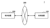
- FIG. 1 is a diagram illustrating an example of a schematic configuration of a system according to an embodiment of the present disclosure. As shown in FIG. 1, the system 1 includes a processing device 100 and a terminal device 200.
- the processing device 100 and the terminal device 200 are connected by a network 300.
- the network 300 is a wired or wireless transmission path for information transmitted from devices connected by the network 300.
- the network 300 may include, for example, a cellular network, a wired LAN (Local Area Network), or a wireless LAN.
- the processing apparatus 100 is an information processing apparatus that performs various processes.
- the terminal device 200 is an information processing device that functions as an interface with a user. Typically, the system 1 interacts with the user through the cooperation of the processing device 100 and the terminal device 200.
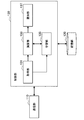
- FIG. 2 is a block diagram illustrating an example of a logical configuration of the processing apparatus 100 according to the present embodiment.
- the processing device 100 includes a communication unit 110, a storage unit 120, and a control unit 130.
- the communication unit 110 has a function of transmitting / receiving information.
- the communication unit 110 receives information from the terminal device 200 and transmits information to the terminal device 200.
- Storage unit 120 The storage unit 120 temporarily or permanently stores a program for operating the processing apparatus 100 and various data.
- Control unit 130 provides various functions of the processing apparatus 100.
- the control unit 130 includes an acquisition unit 131, a calculation unit 133, a learning unit 135, and a notification unit 137.
- Control unit 130 may further include other components other than these components. That is, the control unit 130 can perform operations other than the operations of these components.
- the acquisition unit 131 acquires information.
- the calculation unit 133 performs various calculations using an auto encoder described later.
- the learning unit 135 performs learning related to an auto encoder described later.
- the notification unit 137 notifies the terminal device 200 of information indicating the calculation result by the calculation unit 133. Other detailed operations will be described in detail later.
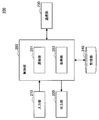
- FIG. 3 is a block diagram illustrating an example of a logical configuration of the terminal device 200 according to the present embodiment.
- the terminal device 200 includes an input unit 210, an output unit 220, a communication unit 230, a storage unit 240, and a control unit 250.
- the input unit 210 has a function of accepting input of information.
- the input unit 210 receives input of information from the user.
- the input unit 210 may accept a character input using a keyboard or a touch panel, a voice input, or a gesture input.
- the input unit 210 may accept data input from a storage medium such as a flash memory.
- the output unit 220 has a function of outputting information.
- the output unit 220 outputs information by image, sound, vibration, light emission, or the like.
- the communication unit 230 has a function of transmitting and receiving information.
- the communication unit 230 receives information from the processing device 100 and transmits information to the processing device 100.
- Storage unit 240 The storage unit 240 temporarily or permanently stores a program for operating the terminal device 200 and various data.
- Control unit 250 provides various functions of the terminal device 200.
- the control unit 250 includes a notification unit 251 and an acquisition unit 253.
- the control unit 250 may further include other components other than these components. That is, the control unit 250 can perform operations other than the operations of these components.
- the notification unit 251 notifies the processing device 100 of information indicating the user input input to the input unit 210.
- the acquisition unit 253 acquires information indicating the calculation result by the processing device 100 and causes the output unit 220 to output the information. Other detailed operations will be described in detail later.
- the intermediate variable z in the auto encoder is also regarded as a feature amount for expressing the data x.
- the method of capturing the intermediate variable z as a feature amount is effective when the feature amount representing the data x is difficult to design. Design difficulties are, for example, difficult to obtain as data, difficult to quantify, a concept in which multiple concepts are fused and their combination is unknown, or it can be completely expressed as a concept in the first place. It means no etc. In such a case, it is desirable to represent the feature quantity by a neural network and leave the handling of the feature quantity to the neural network.
- a feature quantity that is easy to design is also conceivable as information for expressing the data x.
- “Easy design” means, for example, that it can be easily expressed as a concept and that it is easy to quantify the feature value corresponding to the concept. Since the feature quantity that is easy to design is a feature quantity that has a corresponding concept (hereinafter also referred to as a label), it is hereinafter also referred to as labeled feature information (corresponding to the first feature information that is given meaning).
- labeled feature information corresponding to the first feature information that is given meaning
- a feature quantity that is difficult to design expressed by the intermediate variable z is a feature quantity that does not have a corresponding label, and is hereinafter also referred to as unlabeled feature information (corresponding to second feature information that is not given meaning).
- the labeled feature information may be input to the neural network separately from the unlabeled feature information.
- Equation (2) indicating the generated net is changed as follows.
- y is feature information with a label
- z is feature information without a label
- the identification net is expressed by the following function.
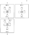
- FIG. 4 is a diagram for explaining the outline of the auto encoder according to this embodiment.
- the auto encoder 10 includes an identification net 11, an inference net 13, and a generation net 15.
- the identification net 11 includes a discriminator 12 corresponding to the function h ⁇ ( ⁇ ) shown in the mathematical formula (7), which is a discriminating unit for discriminating the labeled feature information y from the data x.
- the inference net 13 includes an inference unit 14 corresponding to the function f ⁇ ( ⁇ ) shown in the above equation (6), which is an inference unit for inferring unlabeled feature information z from the data x and the labeled feature information y.
- the inference net 13 can also be understood as removing feature information y with label from data x and extracting feature information z without label.
- the generation net 15 is a generation unit that generates data x having the features indicated by the labeled feature information y and the unlabeled feature information z from the labeled feature information y and the unlabeled feature information z. It includes a generator 16 corresponding to the function g ⁇ (•) shown.
- the labeled feature information y may be a 10-dimensional feature value
- the unlabeled feature information z may be a 50-dimensional feature value.
- a 60-dimensional feature value in which the feature values are connected in series is input to the generator 16.
- the labeled feature information y is a multidimensional feature amount indicating the feature of the time-series data x.
- the labeled feature information y may include information indicating the framework of the time series data x.
- the information indicating the framework is information indicating the basic structure of the target time series data x.
- the information indicating the framework is also referred to as framework information below.
- the labeled feature information y can include information indicating the context of the time-series data x as a feature that can be easily expressed as a concept.
- the context information is information indicating a situation in which target time-series data x is generated.
- the information indicating the context is also referred to as context information below.
- the unlabeled feature information z is a multidimensional feature amount indicating the feature of the time series data x.
- the system 1 learns parameters of a neural network (that is, each of an inference unit, a discriminator, and a generator). For example, the system 1 learns to optimize a predetermined objective function.
- the feature information y with label does not need to be associated as shown in FIG. In the latter case, the system 1 may estimate the labeled feature information y by the identification net 11 and associate it with the time-series data x. In addition, the association between the labeled feature information y and the time-series data x may be performed by the user.
- the system 1 may learn the unlabeled feature information z. Learning in this case refers to inferring unlabeled feature information z corresponding to the time-series data x by the inference net 13 after the parameter learning. The same applies to the feature information y with label.
- the learning result can be stored in the storage unit 120, for example.
- the system 1 (for example, the calculation unit 133) generates time-series data x using the learned neural network. Specifically, the system 1 inputs the feature information with label y and the feature information z without label to the generator 16 to generate time-series data x having the features indicated by the feature information with label y and the feature information z without label. To do. As a result, the system 1 can generate time-series data x reflecting both difficult-to-design feature quantities and easy-to-design feature quantities.
- System 1 may acquire feature information y with label and feature information z without label used for generation.
- the acquisition source may be variously considered as another device (for example, the terminal device 200) or the storage unit 120.
- the feature information y with label used for generation may be output from the discriminator 12, and the feature information z without label used for generation is output from the inference device 14. Also good.
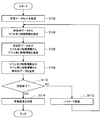
- FIG. 5 is a flowchart showing an example of the flow of learning processing executed in the processing apparatus 100 according to the present embodiment.
- the acquisition unit 131 acquires a learning data set (step S102).
- the learning unit 135 identifies the labeled feature information y from the time series data included in the learning data set by the classifier 12 (step S104).
- the learning unit 135 obtains the unlabeled feature information z from the time series data included in the learning data set and the labeled feature information y included in the learning data set or identified by the classifier 12 by the inference unit 14. Inference is performed (step S106).
- the learning unit 135 generates time-series data x from the labeled feature information y included in the learning data set or identified by the classifier 12 and the inferred unlabeled feature information z by the generator 16 ( Step S108).
- the learning unit 135 determines whether to end the learning (step S110). For example, the learning unit 135 determines to end when the difference between the time series data x included in the learning data set and the generated time series data x is equal to or less than a predetermined threshold, and determines not to end when the difference is exceeded. To do. The same applies to the feature information y with label.
- the learning unit 135 updates the parameters (for example, weight parameters and bias) of the neural network (the discriminator 12, the inference unit 14, and / or the generator 16) (step S112). Thereafter, the process returns to step S104 again.
- storage part 120 memorize
- FIG. 6 is a sequence diagram showing an example of the flow of interaction processing executed in the system 1 according to the present embodiment.
- the processing device 100 and the terminal device 200 are involved in this sequence.
- the terminal device 200 receives user input of the feature information y with label and the feature information z without label (step S202).
- the terminal device 200 (for example, the notification unit 251) notifies the processing device 100 of the labeled feature information y and the unlabeled feature information z, and the processing device 100 (for example, the acquisition unit 131) acquires (step S204). .
- the processing device 100 (for example, the calculation unit 133) generates time-series data x using the notified feature information y with label and feature information z without label (step S206).
- the processing device 100 (for example, the notification unit 137) notifies the generated time series data x to the terminal device 200, and the terminal device 200 (for example, the acquisition unit 253) acquires (step S208).
- the terminal device 200 (for example, the output unit 220) outputs the acquired time series data x (step S210).
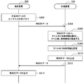
- FIG. 7 is a sequence diagram showing an example of the flow of interaction processing executed in the system 1 according to the present embodiment.
- the processing device 100 and the terminal device 200 are involved in this sequence.
- the terminal device 200 receives user input of the time series data x (step S302).
- the terminal device 200 receives user input of the time series data x (step S302).
- the terminal device 200 (for example, the notification unit 251) notifies the processing device 100 of the time series data x
- the processing device 100 for example, the acquisition unit 131) acquires (step S304).
- the processing device 100 for example, the arithmetic unit 133) identifies the feature information y with label from the time series data x and infers feature information z without label (step S306).
- the processing device 100 changes the feature information y with label for a response to a user input, for example (step S308), and includes feature information z without label and feature information with label after change.
- Time series data x is generated using y (step S310).
- the processing device 100 (for example, the notification unit 137) notifies the generated time series data x to the terminal device 200, and the terminal device 200 (for example, the acquisition unit 253) acquires (step S312).
- the terminal device 200 for example, the output unit 220) outputs the acquired time series data x (step S314).
- processing apparatus 100 The basic technical features of the processing apparatus 100 according to this embodiment have been described above. Next, various embodiments of the processing apparatus 100 will be specifically described.
- the time series data x is voice data including speech.
- Time series data x is voice data obtained by reading out text information.
- the labeled feature information y and the unlabeled feature information z are information indicating the features of the audio data x.
- the feature information is collectively referred to as voice feature information.
- the voice feature information expresses a feature related to the individuality of the speaker represented by a voiceprint, a feature related to the background of the speaker such as resentment or intonation, and a feature such as emotion.
- the context information in the labeled feature information y may include information indicating the speaker's context.
- the context information includes, for example, a label for identifying an individual, a generation (for example, a child, an adult), a man and a woman, a resentment (for example, a speaker's home region), a state (for example, emotions such as emotions), and a occupation (for example, an announcer). , Information on the speaker itself such as a stewardess or an elevator guide).
- the context information may be information related to an environment in which a speaker speaks, such as a speaking partner (for example, a speaker's child, husband, etc.), a talking area or place (for example, work, school, home, etc.).
- the context information may be information related to a topic spoken by the speaker, such as a context before and after the talk, a topic (for example, public talk, serious consultation, etc.).
- the frame information in the feature information y with label is text information such as a speech manuscript or a movie speech.
- the framework information can be 26-dimensional information corresponding to, for example, 26 letters of the alphabet.
- the unlabeled feature information z indicates features other than the labeled feature information y in the voice feature information.
- the unlabeled feature information z is also referred to as utterance style information.
- Neural network configuration The configuration of the neural network according to this embodiment will be described with reference to FIGS.
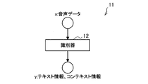
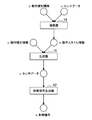
- FIG. 8 is a diagram showing an example of the configuration of the identification net 11 according to the present embodiment. As shown in FIG. 8, the discriminator 12 identifies text information and context information from voice data.
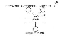
- FIG. 9 is a diagram illustrating an example of the configuration of the inference net 13 according to the present embodiment.
- the inference unit 14 infers utterance style information from text information, context information, and voice data.
- FIG. 10 is a diagram illustrating an example of the configuration of the generation net 15 according to the present embodiment.
- the generator 16 generates audio data from text information, context information, and speech style information.
- the system 1 learns parameters of a neural network (that is, each of an inference unit, a discriminator, and a generator). For example, the system 1 learns to optimize a predetermined objective function.
- the system 1 may learn voice feature information. Learning in this case refers to inferring utterance style information corresponding to speech data by the inference unit 14 after the parameter learning.
- the system 1 may perform learning by connecting the identification net 11 and the generation net 15 to infer utterance style information.
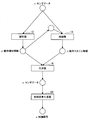
- FIG. 11 is a diagram for explaining an example of inference processing according to the present embodiment. What should be noted here is that the text information and context information output from the discriminator 12 are input to the inference unit 14 and the input is only voice data. Thereby, a user's operation load is reduced.
- the system 1 may store the learned voice feature information in association with the identification information. As a result, the voice feature information can be edited by selecting a speaker, which will be described later.
- TTS text to speech
- TTS is a technique for automatically generating voice data from text, and can generate voice data at a lower cost than when recording by uttering a voice actor or the like.
- the system 1 uses, for example, the generator 16 that inputs the voice feature information in addition to the text information, instead of the TTS engine, thereby generating voice data that reflects, for example, the beat.
- the user can generate voice data in which the text information is read out by voice having desired characteristics by inputting the text information desired to be converted into voice data and desired voice feature information into the system 1. .
- the user can edit the voice feature information.
- the user edits the voice feature information via the terminal device 200.
- the editing of the audio feature information may be performed by a function or a command line interface, or may be performed by a graphical interface or the like.
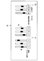
- FIG. 12 shows an example of a graphical interface.
- FIG. 12 is a diagram illustrating an example of a user interface according to the present embodiment.
- a voice feature information editing screen 20 shown in FIG. 12 is displayed by, for example, the terminal device 200 and accepts a voice feature information editing operation by the user.
- the audio feature information editing screen 20 includes an adjustment unit 21 for multidimensional feature amounts z 0 to z 49 that are utterance style information, and a multidimensional feature amount adjustment unit 22 that is context information. Including. Labels such as “joy”, “anger”, and “sorrow”, and “region A”, “region B”, and “region C” are associated with the multi-dimensional feature amount that is context information.
- the labels may be categorized as “feeling” for “joy”, “anger”, and “sorrow”, and “region A”, “region B”, and “region C” as “growing”, respectively.
- the user can adjust each feature amount by moving the knob 23 indicating the value of each feature amount up and down.
- the user can intentionally adjust the feature amount corresponding to the concept of emotion or resentment so that sound data having a desired feature is generated by operating the adjustment unit 22. Is possible.
- the user can perform trial and error by operating the adjustment unit 21 so that sound data having desired characteristics is generated. In this way, the user can easily control the characteristics of audio data other than text information.
- the user can control the feature of the voice data with the compressed information of the limited number of voice feature information, so that the operation load is reduced.
- GUI editing can be finely edited. Therefore, editing by GUI is useful for creating audio contents by professional users.
- application scene for example, in the process of creating animation or CG (Computer Graphics), creation of scenes and lines, and creation of audio content after creation of moving image content can be mentioned.
- CG Computer Graphics
- the editing operation of the voice feature information may be performed by the user selecting the speaker. In this case, the operation load on the user is further reduced.
- the system 1 (for example, the storage unit 120) stores a combination of speaker identification information and voice feature information in advance as a voice feature information DB.
- FIG. 13 is a diagram showing an example of the audio feature information DB according to the present embodiment. As shown in FIG. 13, the system 1 stores identification information of each speaker and voice feature information in association with each other. Note that the speaker identification information is also regarded as the voice feature information identification information.
- FIG. 14 is a diagram illustrating an example of a user interface according to the present embodiment.
- a speaker selection screen 30 shown in FIG. 14 is displayed by the terminal device 200, for example, and accepts a speaker selection operation by the user. For example, it is assumed that the user selects “Speaker X” on the speaker selection screen 30 shown in FIG. Then, the processing apparatus 100 (for example, the acquisition unit 141) acquires the identification information of “speaker X” (that is, identification information of the voice feature information). Then, the processing device 100 (for example, the arithmetic unit 133) generates audio data having a feature indicated by the audio feature information corresponding to the identification information.
- the speaker's choice may be an individual name or a group name.
- the choice of the speaker may be a person who actually exists. In this case, voice data is generated as if a person who actually exists read the text.
- the choices of speakers are “announcer”, “bus guide”, “yakuza”, “teacher”, “doctor”, “kabuki actor”, “rakugoka”, “butler”, etc. It may be a name. In that case, voice data in which a text is read out in a typical way of speaking of each occupation person is generated.
- the speaker's choice may be a character such as a movie or an animation work.
- the choice of the speaker may be a race in a fantasy work such as “Fairy”, “Yokai”, “Monster”, or an occupation in a fantasy work such as “Mage”.
- the voice feature information may be adjusted on the voice feature information editing screen 20 shown in FIG.
- voice data as if the selected person read the text with a different voice from the person himself / herself can be generated.
- the editing by speaker selection described above is simpler than the editing by GUI. Therefore, editing by speaker selection is useful for light users who are not satisfied with the default mechanical voice, but are satisfied with some degree of customization.
- a voice switching of a voice assist agent that provides information by voice.
- the editing operation of the voice feature information may be performed based on the recognition result of the user voice. In this case, the operation load on the user is further reduced.
- the context information can be edited in response to an instruction by the user voice.
- the user edits the context information by speaking a context information adjustment instruction.
- the system 1 (for example, the calculation unit 133) increases the value of the feature amount corresponding to “joy”.
- the system 1 may also control a feature quantity having an effect contrary to the feature quantity designated by the user in order to support an editing operation designated by the user. For example, when the user utters “speak more honest”, the system 1 may decrease the value of the feature amount corresponding to “anger”, “sorrow”, and “easy”.
- the user may edit the voice feature information by feeding back the quality of the voice feature information.
- the system 1 outputs voice data while changing the voice feature information at an appropriate granularity such as for each utterance, and the user feeds back “good” or “bad”. Then, the system 1 controls each feature amount so that it is close to the voice feature information fed back as “good” and far from the voice feature information fed back as “bad”.
- the voice feature information may be automatically edited according to the user voice without being explicitly performed by the user.
- the audio feature information used for generating the audio data may be feature information indicating a feature corresponding to the feature of the user voice. In this case, the user's operation load is further reduced because the user's favorite audio data is generated without editing the audio feature information.
- the system 1 may generate voice data using the voice feature information indicating the feature of the user voice as it is.
- the system 1 identifies or infers voice feature information (eg, context information and utterance style information) from the user voice using the discriminator 12 and the reasoner 14, and newly acquired text for the response Audio data is generated based on the information.
- voice feature information eg, context information and utterance style information
- the system 1 can respond to the user voice with the same stroke as the user's stroke or can respond to the user voice at the same speed as the user speaks.
- the system 1 may control the voice feature information according to the user attribute or state.
- the system 1 uses voice feature information corresponding to the user's “gender”, “age”, “who”, “feeling emotional”, “birthplace”, “race”, “degree of concentration in the system”, and the like. Audio data may be generated.
- these attributes or states can be acquired from a user database prepared in advance or a result of image recognition or voice recognition. By such automatic editing, the system 1 can respond slowly to children, for example, and can respond to elderly people at a high volume.
- a translation scene is an example of a scene where automatic editing is applied according to the user's voice.
- the system 1 by applying automatic editing in accordance with the user voice, the system 1 generates voice data reflecting voice feature information similar to the user voice while translating text included in the user voice. It is possible. Therefore, it is possible to leave nuances such as voice prints and emotions included in the original voice in the translated voice. This makes it possible to meet the potential needs of users who want to listen to the translated speech of movies or speech in the original speaker's voice color or to feel the speaker's emotions etc. realistically only from the speech. It becomes.
- FIG. 15 the processing by the processing apparatus 100 in the translation scene will be described in detail.
- FIG. 15 is a view for explaining audio data generation processing in a translation scene according to the present embodiment.
- the system 1 uses the discriminator 12, the reasoner 14, the generator 16, and the translator 42 to generate speech data translated from the speech data.
- the system 1 (for example, the acquisition unit 141) acquires the speech data x to be translated by dividing it into appropriate sections.
- the system 1 (for example, the arithmetic unit 133) inputs the speech data x to be translated into the discriminator 12, and estimates the text information y and the context information y.
- the text information y and the context information y may be estimated by a person other than the discriminator 12 or by a voice recognizer or the like.
- the system 1 inputs the speech data x, the text information y, and the context information y to the inference device 14 and estimates the speech style information z.
- the system 1 inputs the text information y to the translator 42 and estimates the text information y ′ obtained by translating the text information y into a desired language. The translation may be performed by a person other than the translator 42.
- the system 1 inputs the translated text information y ′ and the utterance style information z to the generator 16 to generate translated speech data x ′.
- the system 1 may also input the context information y to the generator 16.
- the processing apparatus 100 may remove the feature amount of speech from the audio feature information input to the generator 16.
- the system 1 may generate music data that is played according to the score, using the score as the framework information.
- the discriminator 12 has an automatic music recording function for identifying musical score information from music data.
- the inference unit 14 infers music feature information indicating, for example, a player's characteristics, musical instrument characteristics, and acoustic characteristics of the performance venue from the music data and score information. Note that at least part of the music feature information may be identified by the identifier 12.
- the generator 16 generates music data from the score information and the music feature information. Thereby, the system 1 can generate music data in which, for example, a score, a performer, a musical instrument, a performance hall, or the like is changed.
- the music data recorded in a place with a poor acoustic state it is possible to improve the acoustic state of the music data by changing the music feature information to a place with a good acoustic state.
- performance styles, song replacement, singer or lyrics replacement, and the like are possible.
- the time series data x is sensor data obtained by sensing an animal body with a sensor.
- Time series data x is sensor data obtained by sensing a moving object.
- sensing objects such as humans, animals, cars, and insects.
- the sensor for sensing may be an arbitrary sensor such as an acceleration sensor or a gyro sensor.
- the sensor may be an image sensor, and the time series data x may be moving image data.
- the labeled feature information y and the unlabeled feature information z are information indicating the characteristics of the motion of the sensing object.
- the feature information is collectively referred to as operation feature information.
- the motion feature information expresses features such as the motion type, motion magnitude, and frequency of the moving object.
- Context information of the feature information y with label is information indicating, for example, the action type of the moving object.
- the action type when the moving object is a human, for example, “standing”, “sitting”, “walking”, “running” and the like can be mentioned.
- examples of the action type include “fly” and “call a friend” when the moving object is an insect.
- information indicating such an operation type is also referred to as operation type information.
- the framework information is information indicating the structure of the behavior of the moving object, for example.
- the information indicating the composition of the behavior is information such as walking for 10 seconds and running for 10 seconds, for example.
- the description of the framework information is omitted to simplify the description.
- the unlabeled feature information z indicates features other than the labeled feature information y in the operation feature information.
- the unlabeled feature information z is also referred to as operation style information.
- Neural network configuration The configuration of the neural network according to the present embodiment will be described with reference to FIGS.
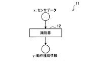
- FIG. 16 is a diagram illustrating an example of the configuration of the identification net 11 according to the present embodiment. As shown in FIG. 16, the discriminator 12 identifies the operation type information from the sensor data.
- FIG. 17 is a diagram illustrating an example of the configuration of the inference net 13 according to the present embodiment. As shown in FIG. 17, the inference unit 14 infers action style information from action type information and sensor data.
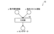
- FIG. 18 is a diagram illustrating an example of the configuration of the generation net 15 according to the present embodiment. As shown in FIG. 18, the generator 16 generates sensor data from the action type information and the action style information.
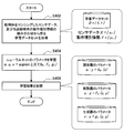
- the system 1 learns parameters of a neural network (that is, each of an inference unit, a discriminator, and a generator). For example, the system 1 learns to optimize a predetermined objective function. An example of the flow of processing related to this learning will be described with reference to FIG.
- FIG. 19 is a flowchart illustrating an example of the flow of learning processing executed in the processing device 100 according to the present embodiment.
- the learning unit 135 learns the parameters of the neural network so as to minimize the objective function L according to the following equation (step S404).
- w is a parameter of the discriminator 12
- u is a parameter of the inference unit 14
- v is a parameter of the generator 16.
- the objective function L may be in the form shown in the above mathematical formula (3).
- storage part 120 memorize
- the system 1 may learn the operation feature information. Learning in this case refers to identifying or inferring action type information or action style information corresponding to sensor data by the discriminator 12 or the inference unit 14 after the parameter learning.
- the system 1 may store the learned operation feature information in association with the identification information. Thereby, the operation style information can be edited by selecting the identification information described later.
- the user can edit the operation feature information.
- the user edits the operation feature information via the terminal device 200.
- the editing of the motion feature information can be performed in the same manner as the editing of the audio feature information described above.
- the GUI will be described with reference to FIG. 20, and description of the other will be omitted.
- FIG. 20 is a diagram illustrating an example of a user interface according to the present embodiment.
- An operation feature information editing screen 50 shown in FIG. 20 is displayed by the terminal device 200, for example, and accepts an operation for editing operation feature information by a user.
- the action feature information editing screen 50 includes an adjustment unit 51 for multidimensional feature quantities z 0 to z 49 that are action style information, and a multidimensional feature quantity adjustment unit 52 that is action type information. including. Labels such as “walking”, “running”, and “standing” are associated with the multi-dimensional feature quantity that is the action type information. The labels may be categorized as “walking”, “running” and “standing” into “human motion”.
- the user can adjust each feature amount by moving up and down the knob 53 indicating the value of each feature amount.
- the moving object may be a robot or a device having an actuator.
- the system 1 may generate a control signal for operating the actuator included in the moving object as time series data x.
- the system 1 (for example, the arithmetic unit 133) generates a control signal corresponding to the sensor data. If the correspondence between the control signal and sensor data obtained by sensing the device having the actuator that operates based on the control signal is known, the system 1 generates a control signal for causing the device to perform a desired operation. It becomes possible.
- An example of the configuration of the generation net 15 for generating such a control signal will be described with reference to FIG.
- FIG. 21 is a diagram illustrating an example of the configuration of the generation net 15 according to the present embodiment.
- the control signal generator 62 is connected to the generator 16 in the generation net 15 according to the present embodiment.
- the control signal generator 62 has a function of generating a corresponding control signal s from the sensor data x. Therefore, the generation net 15 can generate the control signal s for causing the device having the actuator to perform the operation having the characteristics indicated by the operation type information y and the operation style information.
- the control signal generator 62 may be configured by a neural network, more specifically, a feedforward network. An example of the flow of parameter learning processing of the control signal generator 62 will be described with reference to FIG.
- FIG. 22 is a flowchart illustrating an example of the flow of learning processing executed in the processing device 100 according to the present embodiment.
- the learning unit 135 learns the parameters of the neural network so as to minimize the objective function L according to the following equation (step S504).
- a is a parameter of the control signal generator 62.
- the objective function L may be in the form shown in the above mathematical formula (3).
- storage part 120 memorize
- control signal generator 62 and other neural networks may be learned separately or may be learned together. May be.
- the system 1 (for example, the arithmetic unit 133) uses the generator 16 and the control signal generator 62 to generate a control signal from the action type information and the action style information.
- a user can generate a control signal for causing a device having an actuator to perform a desired operation by inputting desired operation type information and style information to the system 1.
- the system 1 may generate a control signal using the generation net 15 shown in FIG. 21, or may generate a control signal by combining the generation net 15 with other components. An example of this will be described with reference to FIGS.
- FIG. 23 is a diagram for explaining an example of a control signal generation process according to the present embodiment.
- the system 1 may generate a control signal by combining the generation net 15 described with reference to FIG. 21 with the inference net 13 described with reference to FIG.
- the inference unit 14 infers the motion style information of the sensing target moving object and inputs it to the generator 16.
- the generator 16 generates sensor data
- the control signal generator 62 generates a control signal.
- the moving object to be sensed may not be a device having an actuator, for example, a person.
- the system 1 can cause, for example, a humanoid robot to perform an operation similar to that of a person based on sensor data obtained by sensing a person.
- FIG. 24 is a diagram for explaining an example of a control signal generation process according to the present embodiment.
- the system 1 may generate a control signal by combining the operation net information selector 64 with the generation net 15 described with reference to FIG.
- the action style information selector 64 has a function of outputting action style information corresponding to the identification information selected by the user, for example. The association between the identification information and the action style information is performed by the learning described above.
- FIG. 25 is a diagram for explaining an example of a control signal generation process according to the present embodiment.
- the system 1 combines the generated net 15 described with reference to FIG. 21 with the identification net 11 described with reference to FIG. 16 and the inference net 13 described with reference to FIG. A control signal may be generated.
- the operation type information y output from the discriminator 12 is input to the inference device 14 and the input is only the sensor data x accordingly. Thereby, a user's operation load is reduced.
- the time-series data x is generated from the feature information y with label and the feature information z without label.
- the time series data x, the labeled feature information y, and the unlabeled feature information z are not limited to the above-described example, and can be considered in various ways.
- the feature information y with label may be a score
- the feature information z without label may be a performance feature and a singing feature
- the time series data x may be song data.
- the system 1 learns performance characteristics and singing characteristics from a data set including a plurality of combinations of music score and singing data including lyrics of a certain artist, and different artists as if the artist sang. Singing data corresponding to the score can be generated.
- the labeled feature information y may be a novel plot
- the unlabeled feature information z may be a writer feature (for example, style)
- the time-series data x may be a novel.
- the system 1 learns the writer's characteristics from a data set including a plurality of combinations of plots and novels of a certain writer, and generates a novel corresponding to the newly input plot as if the writer wrote. It becomes possible to do.
- the feature information with label y may be text information in a first language
- the feature information without label z may be a language feature
- the time series data x may be second text information.
- the system 1 learns language features using a bilingual corpus (that is, a data set) including Japanese text and English text, and converts newly input Japanese text into English text. It becomes possible to output.
- the labeled feature information y may be a picture plot
- the unlabeled feature information z may be a painter feature
- the time-series data x may be a drawing order.
- the system 1 learns the painter characteristics from a data set including a plurality of combinations of a plot of a picture such as “Many sunflowers are under the blue sky” and a drawing order of pictures drawn based on the plot. It is possible to generate a drawing order for the newly input picture plot.
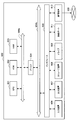
- FIG. 26 is a block diagram illustrating an example of a hardware configuration of the information processing apparatus according to the present embodiment.
- the information processing apparatus 900 illustrated in FIG. 26 can realize, for example, the processing apparatus 100 or the terminal apparatus 200 illustrated in FIGS. 2 and 3, respectively.
- Information processing by the processing device 100 or the terminal device 200 according to the present embodiment is realized by cooperation between software and hardware described below.
- the information processing apparatus 900 includes a CPU (Central Processing Unit) 901, a ROM (Read Only Memory) 902, a RAM (Random Access Memory) 903, and a host bus 904a.
- the information processing apparatus 900 includes a bridge 904, an external bus 904b, an interface 905, an input device 906, an output device 907, a storage device 908, a drive 909, a connection port 911, and a communication device 913.
- the information processing apparatus 900 may include a processing circuit such as a DSP or an ASIC in place of or in addition to the CPU 901.
- the CPU 901 functions as an arithmetic processing unit and a control unit, and controls the overall operation in the information processing apparatus 900 according to various programs. Further, the CPU 901 may be a microprocessor.
- the ROM 902 stores programs used by the CPU 901, calculation parameters, and the like.
- the RAM 903 temporarily stores programs used in the execution of the CPU 901, parameters that change as appropriate during the execution, and the like.
- the CPU 901 can form, for example, the control unit 130 shown in FIG. 2 or the control unit 250 shown in FIG.
- the CPU 901, ROM 902, and RAM 903 are connected to each other by a host bus 904a including a CPU bus.
- the host bus 904 a is connected to an external bus 904 b such as a PCI (Peripheral Component Interconnect / Interface) bus via a bridge 904.
- an external bus 904 b such as a PCI (Peripheral Component Interconnect / Interface) bus
- PCI Peripheral Component Interconnect / Interface
- the host bus 904a, the bridge 904, and the external bus 904b do not necessarily have to be configured separately, and these functions may be mounted on one bus.
- the input device 906 is realized by a device in which information is input by the user, such as a mouse, a keyboard, a touch panel, a button, a microphone, a switch, and a lever.
- the input device 906 may be, for example, a remote control device using infrared rays or other radio waves, or may be an external connection device such as a mobile phone or a PDA that supports the operation of the information processing device 900.
- the input device 906 may include, for example, an input control circuit that generates an input signal based on information input by the user using the above-described input means and outputs the input signal to the CPU 901.
- a user of the information processing apparatus 900 can input various data and instruct a processing operation to the information processing apparatus 900 by operating the input device 906.
- the input device 906 can be formed by a device that detects information about the user.
- the input device 906 includes various sensors such as an image sensor (for example, a camera), a depth sensor (for example, a stereo camera), an acceleration sensor, a gyro sensor, a geomagnetic sensor, an optical sensor, a sound sensor, a distance sensor, and a force sensor. Can be included.
- the input device 906 includes information related to the information processing device 900 state, such as the posture and movement speed of the information processing device 900, and information related to the surrounding environment of the information processing device 900, such as brightness and noise around the information processing device 900. May be obtained.
- the input device 906 receives a GNSS signal from a GNSS (Global Navigation Satellite System) satellite (for example, a GPS signal from a GPS (Global Positioning System) satellite) and receives position information including the latitude, longitude, and altitude of the device.
- GNSS Global Navigation Satellite System
- a GNSS module to measure may be included.
- the input device 906 may detect the position by transmission / reception with Wi-Fi (registered trademark), a mobile phone / PHS / smartphone, or the like, or near field communication.
- Wi-Fi registered trademark
- the input device 906 can form, for example, the input unit 210 shown in FIG.
- the output device 907 is formed of a device that can notify the user of the acquired information visually or audibly.
- Examples of such devices include CRT display devices, liquid crystal display devices, plasma display devices, EL display devices, display devices such as laser projectors, LED projectors and lamps, audio output devices such as speakers and headphones, printer devices, and the like.
- the output device 907 outputs results obtained by various processes performed by the information processing device 900.
- the display device visually displays results obtained by various processes performed by the information processing device 900 in various formats such as text, images, tables, and graphs.
- the audio output device converts an audio signal composed of reproduced audio data, acoustic data, and the like into an analog signal and outputs it aurally.
- the display device or the audio output device can form, for example, the output unit 220 shown in FIG.
- the storage device 908 is a data storage device formed as an example of a storage unit of the information processing device 900.
- the storage apparatus 908 is realized by, for example, a magnetic storage device such as an HDD, a semiconductor storage device, an optical storage device, a magneto-optical storage device, or the like.
- the storage device 908 may include a storage medium, a recording device that records data on the storage medium, a reading device that reads data from the storage medium, a deletion device that deletes data recorded on the storage medium, and the like.
- the storage device 908 stores programs executed by the CPU 901, various data, various data acquired from the outside, and the like.
- the storage device 908 can form, for example, the storage unit 120 shown in FIG. 2 or the storage unit 240 shown in FIG.
- the drive 909 is a storage medium reader / writer, and is built in or externally attached to the information processing apparatus 900.
- the drive 909 reads information recorded on a removable storage medium such as a magnetic disk, an optical disk, a magneto-optical disk, or a semiconductor memory, and outputs the information to the RAM 903.
- the drive 909 can also write information to a removable storage medium.
- connection port 911 is an interface connected to an external device, and is a connection port with an external device capable of transmitting data by USB (Universal Serial Bus), for example.
- USB Universal Serial Bus
- the communication device 913 is a communication interface formed by a communication device or the like for connecting to the network 920, for example.
- the communication device 913 is, for example, a communication card for wired or wireless LAN (Local Area Network), LTE (Long Term Evolution), Bluetooth (registered trademark), or WUSB (Wireless USB).
- the communication device 913 may be a router for optical communication, a router for ADSL (Asymmetric Digital Subscriber Line), a modem for various communication, or the like.
- the communication device 913 can transmit and receive signals and the like according to a predetermined protocol such as TCP / IP, for example, with the Internet and other communication devices.
- the communication device 913 can form, for example, the communication unit 110 illustrated in FIG. 2 or the communication unit 230 illustrated in FIG.
- the network 920 is a wired or wireless transmission path for information transmitted from a device connected to the network 920.
- the network 920 may include a public line network such as the Internet, a telephone line network, a satellite communication network, various LANs including Ethernet (registered trademark), a WAN (Wide Area Network), and the like.
- the network 920 may include a dedicated line network such as an IP-VPN (Internet Protocol-Virtual Private Network).
- IP-VPN Internet Protocol-Virtual Private Network
- each of the above components may be realized using a general-purpose member, or may be realized by hardware specialized for the function of each component. Therefore, it is possible to change the hardware configuration to be used as appropriate according to the technical level at the time of carrying out this embodiment.
- a computer program for realizing each function of the information processing apparatus 900 according to the present embodiment as described above can be produced and mounted on a PC or the like.
- a computer-readable recording medium storing such a computer program can be provided.
- the recording medium is, for example, a magnetic disk, an optical disk, a magneto-optical disk, a flash memory, or the like.
- the above computer program may be distributed via a network, for example, without using a recording medium.
- the system 1 uses the first feature information with meaning (that is, feature information with label) and the second feature information with no meaning (that is, feature information without label).
- the time series data having the features indicated by the feature information with label and the feature information without label is generated. This makes it possible to appropriately characterize the data. More specifically, the user can easily generate time-series data having a desired feature by selecting or editing feature information with a label and feature information without a label according to a desired feature. Is possible.
- the processing device 100 and the terminal device 200 are described as separate devices, but the present technology is not limited to such an example.
- the processing device 100 and the terminal device 200 may be realized as one device.
- An acquisition unit that acquires first feature information that is given meaning and second feature information that is not given meaning;
- a generating unit that generates time-series data having the characteristics indicated by the first feature information and the second feature information acquired by the acquiring unit;
- An information processing apparatus comprising: (2) The information processing apparatus according to (1), wherein the first feature information includes information indicating a context of the time-series data.
- the information indicating the framework is text information
- the information processing apparatus according to (3), wherein the time-series data is voice data obtained by reading the text information.
- the information processing apparatus includes information regarding the speaker itself.
- the information processing apparatus includes information regarding an environment in which a speaker speaks.
- the information processing apparatus includes information related to a topic spoken by a speaker.
- the information indicating the framework is music score information, The information processing apparatus according to (3), wherein the time-series data is music data played according to the score information.
- the information indicating the context is information indicating an operation type, The information processing apparatus according to (2) or (3), wherein the time-series data is sensor data obtained by sensing a moving object.
- the information indicating the context is information indicating an operation type
- the information processing apparatus according to (2) or (3), wherein the time-series data is a control signal for operating an actuator included in a moving object.
- the acquisition unit acquires identification information corresponding to the first feature information and the second feature information
- the information processing apparatus according to any one of (1) to (12), wherein the generation unit generates time-series data having characteristics corresponding to the identification information.
- the information processing apparatus according to any one of (1) to (13), wherein the generation unit generates the time-series data using a neural network.
- the information processing apparatus according to (14), further including a learning unit that learns parameters of the neural network.
- the information processing apparatus according to any one of (1) to (15), further including an identification unit that identifies the first feature information from the time-series data.
- the information processing apparatus further includes an inference unit that infers the second feature information from the time series data and the first feature information. Processing equipment.
- a notifying unit for notifying other devices of the first feature information with meaning and the second feature information without meaning An acquisition unit that acquires time-series data having the characteristics indicated by the first feature information and the second feature information from the other device;
- An information processing apparatus comprising: (19) Obtaining meaningful first feature information and non-meaning second feature information; Generating time-series data having the characteristics indicated by the acquired first characteristic information and the second characteristic information by a processor;
- An information processing method including: (20) Notifying other devices of the first feature information that is given meaning and the second feature information that is not given meaning; Obtaining time-series data having the features indicated by the first feature information and the second feature information from the other device by a processor;
- An information processing method including:
Landscapes
- Engineering & Computer Science (AREA)
- Physics & Mathematics (AREA)
- Theoretical Computer Science (AREA)
- Health & Medical Sciences (AREA)
- Computational Linguistics (AREA)
- Artificial Intelligence (AREA)
- General Physics & Mathematics (AREA)
- General Engineering & Computer Science (AREA)
- General Health & Medical Sciences (AREA)
- Software Systems (AREA)
- Data Mining & Analysis (AREA)
- Evolutionary Computation (AREA)
- Mathematical Physics (AREA)
- Computing Systems (AREA)
- Biophysics (AREA)
- Molecular Biology (AREA)
- Biomedical Technology (AREA)
- Life Sciences & Earth Sciences (AREA)
- Multimedia (AREA)
- Human Computer Interaction (AREA)
- Audiology, Speech & Language Pathology (AREA)
- Acoustics & Sound (AREA)
- Probability & Statistics with Applications (AREA)
- Computer Vision & Pattern Recognition (AREA)
- Psychiatry (AREA)
- Social Psychology (AREA)
- Machine Translation (AREA)
Abstract
Priority Applications (3)
| Application Number | Priority Date | Filing Date | Title |
|---|---|---|---|
| EP16897086.1A EP3438972B1 (fr) | 2016-03-28 | 2016-12-14 | Système et procédé de traitement de l'information pour la génération de parole |
| JP2018508391A JPWO2017168870A1 (ja) | 2016-03-28 | 2016-12-14 | 情報処理装置及び情報処理方法 |
| US16/086,636 US20190087734A1 (en) | 2016-03-28 | 2016-12-14 | Information processing apparatus and information processing method |
Applications Claiming Priority (2)
| Application Number | Priority Date | Filing Date | Title |
|---|---|---|---|
| JP2016-063784 | 2016-03-28 | ||
| JP2016063784 | 2016-03-28 |
Publications (1)
| Publication Number | Publication Date |
|---|---|
| WO2017168870A1 true WO2017168870A1 (fr) | 2017-10-05 |
Family
ID=59962890
Family Applications (1)
| Application Number | Title | Priority Date | Filing Date |
|---|---|---|---|
| PCT/JP2016/087316 Ceased WO2017168870A1 (fr) | 2016-03-28 | 2016-12-14 | Dispositif de traitement d'informations et procédé de traitement d'informations |
Country Status (4)
| Country | Link |
|---|---|
| US (1) | US20190087734A1 (fr) |
| EP (1) | EP3438972B1 (fr) |
| JP (1) | JPWO2017168870A1 (fr) |
| WO (1) | WO2017168870A1 (fr) |
Cited By (19)
| Publication number | Priority date | Publication date | Assignee | Title |
|---|---|---|---|---|
| JP2018036413A (ja) * | 2016-08-30 | 2018-03-08 | 日本電信電話株式会社 | 音声合成学習装置、方法、及びプログラム |
| CN109119090A (zh) * | 2018-10-30 | 2019-01-01 | Oppo广东移动通信有限公司 | 语音处理方法、装置、存储介质及电子设备 |
| CN109326302A (zh) * | 2018-11-14 | 2019-02-12 | 桂林电子科技大学 | 一种基于声纹比对和生成对抗网络的语音增强方法 |
| JP2019079436A (ja) * | 2017-10-26 | 2019-05-23 | 株式会社Preferred Networks | 画像生成方法、画像生成装置、及び画像生成プログラム |
| JP2019109306A (ja) * | 2017-12-15 | 2019-07-04 | 日本電信電話株式会社 | 音声変換装置、音声変換方法及びプログラム |
| WO2019163753A1 (fr) * | 2018-02-20 | 2019-08-29 | 日本電信電話株式会社 | Dispositif, procédé et programme d'analyse de signal vocal |
| JP2019159823A (ja) * | 2018-03-13 | 2019-09-19 | 富士通株式会社 | 学習プログラム、学習方法および学習装置 |
| WO2019244930A1 (fr) * | 2018-06-20 | 2019-12-26 | 日本電信電話株式会社 | Dispositif, procédé et programme de détection |
| JP2020098501A (ja) * | 2018-12-18 | 2020-06-25 | 富士通株式会社 | 学習プログラム、学習方法および学習装置 |
| JP2020154654A (ja) * | 2019-03-19 | 2020-09-24 | 富士通株式会社 | 推定プログラム、推定装置および推定方法 |
| WO2020220541A1 (fr) * | 2019-04-29 | 2020-11-05 | 平安科技(深圳)有限公司 | Procédé et terminal de reconnaissance de locuteur |
| JP2021511536A (ja) * | 2018-01-11 | 2021-05-06 | ネオサピエンス株式会社Neosapience, Inc. | 多言語テキスト音声合成方法 |
| JPWO2020031544A1 (ja) * | 2018-08-10 | 2021-08-02 | ヤマハ株式会社 | 楽譜データの情報処理装置 |
| CN113269222A (zh) * | 2021-03-15 | 2021-08-17 | 上海电气集团股份有限公司 | 用于检测升降设备的特征值选取方法、检测方法和系统 |
| JP2021521492A (ja) * | 2018-05-11 | 2021-08-26 | グーグル エルエルシーGoogle LLC | クロックワーク階層化変分エンコーダ |
| JP2021182159A (ja) * | 2020-10-27 | 2021-11-25 | ベイジン バイドゥ ネットコム サイエンス テクノロジー カンパニー リミテッド | 歌のマルチメディアの合成方法、合成装置、電子機器及び記憶媒体 |
| JP2023505670A (ja) * | 2019-12-10 | 2023-02-10 | グーグル エルエルシー | アテンションベースのクロックワーク階層型変分エンコーダ |
| JP2024003166A (ja) * | 2018-04-11 | 2024-01-11 | ドルビー ラボラトリーズ ライセンシング コーポレイション | 機械学習に基づく音声符号化及び復号のための知覚に基づく損失関数 |
| JP2024502049A (ja) * | 2020-12-30 | 2024-01-17 | アイフライテック カンパニー,リミテッド | 情報合成方法、装置、電子機器及びコンピュータ可読記憶媒体 |
Families Citing this family (11)
| Publication number | Priority date | Publication date | Assignee | Title |
|---|---|---|---|---|
| US12558778B2 (en) * | 2016-09-07 | 2026-02-24 | Autodesk, Inc. | Configuring a robotic camera to mimic cinematographic styles |
| US10971142B2 (en) * | 2017-10-27 | 2021-04-06 | Baidu Usa Llc | Systems and methods for robust speech recognition using generative adversarial networks |
| KR102608469B1 (ko) * | 2017-12-22 | 2023-12-01 | 삼성전자주식회사 | 자연어 생성 방법 및 장치 |
| WO2020089961A1 (fr) * | 2018-10-29 | 2020-05-07 | 健一 海沼 | Dispositif et programme de traitement vocal |
| CN110288965B (zh) * | 2019-05-21 | 2021-06-18 | 北京达佳互联信息技术有限公司 | 一种音乐合成方法、装置、电子设备及存储介质 |
| JP7244390B2 (ja) * | 2019-08-22 | 2023-03-22 | 株式会社ソニー・インタラクティブエンタテインメント | 情報処理装置、情報処理方法およびプログラム |
| CN110930977B (zh) * | 2019-11-12 | 2022-07-08 | 北京搜狗科技发展有限公司 | 一种数据处理方法、装置和电子设备 |
| CN112489606B (zh) * | 2020-11-26 | 2022-09-27 | 北京有竹居网络技术有限公司 | 旋律生成方法、装置、可读介质及电子设备 |
| US11617952B1 (en) | 2021-04-13 | 2023-04-04 | Electronic Arts Inc. | Emotion based music style change using deep learning |
| KR20240016975A (ko) * | 2021-05-05 | 2024-02-06 | 딥 미디어 인크. | 오디오 및 비디오 트렌스레이터 |
| CN114055483A (zh) * | 2021-09-30 | 2022-02-18 | 杭州未名信科科技有限公司 | 一种基于机械臂书写汉字的方法、装置、设备及介质 |
Citations (2)
| Publication number | Priority date | Publication date | Assignee | Title |
|---|---|---|---|---|
| JPH02304493A (ja) * | 1989-05-19 | 1990-12-18 | Hitachi Ltd | 音声合成システム |
| JP2007265345A (ja) * | 2006-03-30 | 2007-10-11 | Sony Corp | 情報処理装置および方法、学習装置および方法、並びにプログラム |
Family Cites Families (2)
| Publication number | Priority date | Publication date | Assignee | Title |
|---|---|---|---|---|
| WO2008149547A1 (fr) * | 2007-06-06 | 2008-12-11 | Panasonic Corporation | Dispositif d'édition de tonalité vocale et procédé d'édition de tonalité vocale |
| EP3151239A1 (fr) * | 2015-09-29 | 2017-04-05 | Yandex Europe AG | Procedes et systemes pour la synthese de texte en discours |
-
2016
- 2016-12-14 EP EP16897086.1A patent/EP3438972B1/fr not_active Not-in-force
- 2016-12-14 JP JP2018508391A patent/JPWO2017168870A1/ja active Pending
- 2016-12-14 WO PCT/JP2016/087316 patent/WO2017168870A1/fr not_active Ceased
- 2016-12-14 US US16/086,636 patent/US20190087734A1/en not_active Abandoned
Patent Citations (2)
| Publication number | Priority date | Publication date | Assignee | Title |
|---|---|---|---|---|
| JPH02304493A (ja) * | 1989-05-19 | 1990-12-18 | Hitachi Ltd | 音声合成システム |
| JP2007265345A (ja) * | 2006-03-30 | 2007-10-11 | Sony Corp | 情報処理装置および方法、学習装置および方法、並びにプログラム |
Non-Patent Citations (3)
| Title |
|---|
| MASAMITSU MURASE: "Ningen Robot Kyocho no Tameno RNNPB ni yoru Giji Symbol no Kakutoku to sono Kaisosei no Kaiseki", DAI 24 KAI ANNUAL CONFERENCE OF THE ROBOTICS SOCIETY OF JAPAN YOKOSHU, September 2006 (2006-09-01), XP009509224 * |
| See also references of EP3438972A4 * |
| TETSUYA OGATA: "Gesture and Sound Generation of Robot based on Cross-Modal Translation using Recurrent Neural Network with Parametric Bias", IEICE TECHNICAL REPORT, vol. 106, no. 298, October 2006 (2006-10-01), pages 27 - 32, XP009509223 * |
Cited By (52)
| Publication number | Priority date | Publication date | Assignee | Title |
|---|---|---|---|---|
| JP2018036413A (ja) * | 2016-08-30 | 2018-03-08 | 日本電信電話株式会社 | 音声合成学習装置、方法、及びプログラム |
| JP7023669B2 (ja) | 2017-10-26 | 2022-02-22 | 株式会社Preferred Networks | 画像生成方法、画像生成装置、及び画像生成プログラム |
| JP2019079436A (ja) * | 2017-10-26 | 2019-05-23 | 株式会社Preferred Networks | 画像生成方法、画像生成装置、及び画像生成プログラム |
| JP2019109306A (ja) * | 2017-12-15 | 2019-07-04 | 日本電信電話株式会社 | 音声変換装置、音声変換方法及びプログラム |
| JP7178028B2 (ja) | 2018-01-11 | 2022-11-25 | ネオサピエンス株式会社 | 多言語テキスト音声合成モデルを利用した音声翻訳方法およびシステム |
| JP2022169714A (ja) * | 2018-01-11 | 2022-11-09 | ネオサピエンス株式会社 | 多言語テキスト音声合成モデルを利用した音声翻訳方法およびシステム |
| JP7142333B2 (ja) | 2018-01-11 | 2022-09-27 | ネオサピエンス株式会社 | 多言語テキスト音声合成方法 |
| US11217224B2 (en) | 2018-01-11 | 2022-01-04 | Neosapience, Inc. | Multilingual text-to-speech synthesis |
| US11810548B2 (en) | 2018-01-11 | 2023-11-07 | Neosapience, Inc. | Speech translation method and system using multilingual text-to-speech synthesis model |
| US12080273B2 (en) | 2018-01-11 | 2024-09-03 | Neosapience, Inc. | Translation method and system using multilingual text-to-speech synthesis model |
| JP7500020B2 (ja) | 2018-01-11 | 2024-06-17 | ネオサピエンス株式会社 | 多言語テキスト音声合成方法 |
| JP7445267B2 (ja) | 2018-01-11 | 2024-03-07 | ネオサピエンス株式会社 | 多言語テキスト音声合成モデルを利用した音声翻訳方法およびシステム |
| US11769483B2 (en) | 2018-01-11 | 2023-09-26 | Neosapience, Inc. | Multilingual text-to-speech synthesis |
| JP2021511536A (ja) * | 2018-01-11 | 2021-05-06 | ネオサピエンス株式会社Neosapience, Inc. | 多言語テキスト音声合成方法 |
| JP2021511534A (ja) * | 2018-01-11 | 2021-05-06 | ネオサピエンス株式会社Neosapience, Inc. | 多言語テキスト音声合成モデルを利用した音声翻訳方法およびシステム |
| JP2022153569A (ja) * | 2018-01-11 | 2022-10-12 | ネオサピエンス株式会社 | 多言語テキスト音声合成方法 |
| JP2019144403A (ja) * | 2018-02-20 | 2019-08-29 | 日本電信電話株式会社 | 音声信号解析装置、方法、及びプログラム |
| US11798579B2 (en) | 2018-02-20 | 2023-10-24 | Nippon Telegraph And Telephone Corporation | Device, method, and program for analyzing speech signal |
| WO2019163753A1 (fr) * | 2018-02-20 | 2019-08-29 | 日本電信電話株式会社 | Dispositif, procédé et programme d'analyse de signal vocal |
| JP2019159823A (ja) * | 2018-03-13 | 2019-09-19 | 富士通株式会社 | 学習プログラム、学習方法および学習装置 |
| JP7106902B2 (ja) | 2018-03-13 | 2022-07-27 | 富士通株式会社 | 学習プログラム、学習方法および学習装置 |
| JP2024003166A (ja) * | 2018-04-11 | 2024-01-11 | ドルビー ラボラトリーズ ライセンシング コーポレイション | 機械学習に基づく音声符号化及び復号のための知覚に基づく損失関数 |
| JP7690545B2 (ja) | 2018-04-11 | 2025-06-10 | ドルビー ラボラトリーズ ライセンシング コーポレイション | 機械学習に基づく音声符号化及び復号のための知覚に基づく損失関数 |
| US12361956B2 (en) | 2018-04-11 | 2025-07-15 | Dolby Laboratories Licensing Corporation | Perceptually-based loss functions for audio encoding and decoding based on machine learning |
| EP4647969A3 (fr) * | 2018-04-11 | 2025-12-17 | Dolby Laboratories Licensing Corporation | Fonctions de perte basées sur la perception pour codage et décodage audio basés sur l'apprentissage automatique |
| JP7376629B2 (ja) | 2018-05-11 | 2023-11-08 | グーグル エルエルシー | クロックワーク階層化変分エンコーダ |
| JP2022071074A (ja) * | 2018-05-11 | 2022-05-13 | グーグル エルエルシー | クロックワーク階層化変分エンコーダ |
| JP2021521492A (ja) * | 2018-05-11 | 2021-08-26 | グーグル エルエルシーGoogle LLC | クロックワーク階層化変分エンコーダ |
| JP7035225B2 (ja) | 2018-05-11 | 2022-03-14 | グーグル エルエルシー | クロックワーク階層化変分エンコーダ |
| JP2019219915A (ja) * | 2018-06-20 | 2019-12-26 | 日本電信電話株式会社 | 検知装置、検知方法および検知プログラム |
| WO2019244930A1 (fr) * | 2018-06-20 | 2019-12-26 | 日本電信電話株式会社 | Dispositif, procédé et programme de détection |
| JP7119631B2 (ja) | 2018-06-20 | 2022-08-17 | 日本電信電話株式会社 | 検知装置、検知方法および検知プログラム |
| JP7230919B2 (ja) | 2018-08-10 | 2023-03-01 | ヤマハ株式会社 | 楽譜データの情報処理装置 |
| JPWO2020031544A1 (ja) * | 2018-08-10 | 2021-08-02 | ヤマハ株式会社 | 楽譜データの情報処理装置 |
| US11967302B2 (en) | 2018-08-10 | 2024-04-23 | Yamaha Corporation | Information processing device for musical score data |
| CN109119090A (zh) * | 2018-10-30 | 2019-01-01 | Oppo广东移动通信有限公司 | 语音处理方法、装置、存储介质及电子设备 |
| CN109326302A (zh) * | 2018-11-14 | 2019-02-12 | 桂林电子科技大学 | 一种基于声纹比对和生成对抗网络的语音增强方法 |
| JP7143752B2 (ja) | 2018-12-18 | 2022-09-29 | 富士通株式会社 | 学習プログラム、学習方法および学習装置 |
| JP2020098501A (ja) * | 2018-12-18 | 2020-06-25 | 富士通株式会社 | 学習プログラム、学習方法および学習装置 |
| JP7205328B2 (ja) | 2019-03-19 | 2023-01-17 | 富士通株式会社 | 推定プログラム、推定装置および推定方法 |
| JP2020154654A (ja) * | 2019-03-19 | 2020-09-24 | 富士通株式会社 | 推定プログラム、推定装置および推定方法 |
| US11145062B2 (en) | 2019-03-19 | 2021-10-12 | Fujitsu Limited | Estimation apparatus, estimation method, and non-transitory computer-readable storage medium for storing estimation program |
| WO2020220541A1 (fr) * | 2019-04-29 | 2020-11-05 | 平安科技(深圳)有限公司 | Procédé et terminal de reconnaissance de locuteur |
| JP2023171934A (ja) * | 2019-12-10 | 2023-12-05 | グーグル エルエルシー | アテンションベースのクロックワーク階層型変分エンコーダ |
| JP7362929B2 (ja) | 2019-12-10 | 2023-10-17 | グーグル エルエルシー | アテンションベースのクロックワーク階層型変分エンコーダ |
| JP7611335B2 (ja) | 2019-12-10 | 2025-01-09 | グーグル エルエルシー | アテンションベースのクロックワーク階層型変分エンコーダ |
| JP2023505670A (ja) * | 2019-12-10 | 2023-02-10 | グーグル エルエルシー | アテンションベースのクロックワーク階層型変分エンコーダ |
| JP7138222B2 (ja) | 2020-10-27 | 2022-09-15 | ベイジン バイドゥ ネットコム サイエンス テクノロジー カンパニー リミテッド | 歌のマルチメディアの合成方法、合成装置、電子機器及び記憶媒体 |
| JP2021182159A (ja) * | 2020-10-27 | 2021-11-25 | ベイジン バイドゥ ネットコム サイエンス テクノロジー カンパニー リミテッド | 歌のマルチメディアの合成方法、合成装置、電子機器及び記憶媒体 |
| JP2024502049A (ja) * | 2020-12-30 | 2024-01-17 | アイフライテック カンパニー,リミテッド | 情報合成方法、装置、電子機器及びコンピュータ可読記憶媒体 |
| JP7605997B2 (ja) | 2020-12-30 | 2024-12-24 | アイフライテック カンパニー,リミテッド | 情報合成方法、装置、電子機器及びコンピュータ可読記憶媒体 |
| CN113269222A (zh) * | 2021-03-15 | 2021-08-17 | 上海电气集团股份有限公司 | 用于检测升降设备的特征值选取方法、检测方法和系统 |
Also Published As
| Publication number | Publication date |
|---|---|
| EP3438972A1 (fr) | 2019-02-06 |
| US20190087734A1 (en) | 2019-03-21 |
| JPWO2017168870A1 (ja) | 2019-02-07 |
| EP3438972B1 (fr) | 2022-01-26 |
| EP3438972A4 (fr) | 2019-07-10 |
Similar Documents
| Publication | Publication Date | Title |
|---|---|---|
| WO2017168870A1 (fr) | Dispositif de traitement d'informations et procédé de traitement d'informations | |
| CN110688911B (zh) | 视频处理方法、装置、系统、终端设备及存储介质 | |
| CN112840398B (zh) | 将音频内容变换为图像 | |
| JP6019108B2 (ja) | 文字に基づく映像生成 | |
| CN118591823A (zh) | 提供交互式化身服务的方法和设备 | |
| JP2014519082A5 (fr) | ||
| CN116597858A (zh) | 语音口型匹配方法、装置、存储介质及电子设备 | |
| CN114154636A (zh) | 数据处理方法、电子设备及计算机程序产品 | |
| WO2021153101A1 (fr) | Dispositif de traitement d'informations, procédé de traitement d'informations et programme de traitement d'informations | |
| CN118898986A (zh) | 语音合成模型训练、语音合成方法及任务平台 | |
| CN117316185A (zh) | 一种音视频的生成方法、装置、设备及存储介质 | |
| CN120340498B (zh) | 一种机器人自适应互动方法及系统 | |
| CN119295608A (zh) | 口型动画生成、模型训练方法、装置、设备及介质 | |
| JP6790791B2 (ja) | 音声対話装置および対話方法 | |
| CN119785756B (zh) | 语音生成中的数据处理方法、装置及电子设备 | |
| JP7714731B1 (ja) | データ処理装置、データ処理方法、及びデータ処理プログラム | |
| CN121580336B (zh) | 用于约束数字人多模态输出的方法、装置及计算机设备 | |
| JP7469211B2 (ja) | 対話型コミュニケーション装置、コミュニケーションシステム及びプログラム | |
| KR20200048976A (ko) | 전자 장치 및 그 제어 방법 | |
| CN121331090A (zh) | 一种语音合成方法及相关装置 | |
| JP2026069001A (ja) | システム | |
| JP2026033169A (ja) | システム | |
| HK40117899A (zh) | 语音合成模型训练、语音合成方法及任务平台 | |
| CN121096315A (zh) | 语音生成方法、装置、电子设备、存储介质及产品 | |
| KR20260054038A (ko) | 사용자 정의 프롬프트 기반의 실시간 인공지능 시각적 페르소나 생성 및 출력 시스템 |
Legal Events
| Date | Code | Title | Description |
|---|---|---|---|
| ENP | Entry into the national phase |
Ref document number: 2018508391 Country of ref document: JP Kind code of ref document: A |
|
| NENP | Non-entry into the national phase |
Ref country code: DE |
|
| WWE | Wipo information: entry into national phase |
Ref document number: 2016897086 Country of ref document: EP |
|
| ENP | Entry into the national phase |
Ref document number: 2016897086 Country of ref document: EP Effective date: 20181029 |
|
| 121 | Ep: the epo has been informed by wipo that ep was designated in this application |
Ref document number: 16897086 Country of ref document: EP Kind code of ref document: A1 |