WO2017168942A1 - Soupape actionnée par moteur - Google Patents
Soupape actionnée par moteur Download PDFInfo
- Publication number
- WO2017168942A1 WO2017168942A1 PCT/JP2017/000963 JP2017000963W WO2017168942A1 WO 2017168942 A1 WO2017168942 A1 WO 2017168942A1 JP 2017000963 W JP2017000963 W JP 2017000963W WO 2017168942 A1 WO2017168942 A1 WO 2017168942A1
- Authority
- WO
- WIPO (PCT)
- Prior art keywords
- valve
- valve body
- motor
- operated
- area
- Prior art date
- Legal status (The legal status is an assumption and is not a legal conclusion. Google has not performed a legal analysis and makes no representation as to the accuracy of the status listed.)
- Ceased
Links
Images


Classifications
-
- F—MECHANICAL ENGINEERING; LIGHTING; HEATING; WEAPONS; BLASTING
- F16—ENGINEERING ELEMENTS AND UNITS; GENERAL MEASURES FOR PRODUCING AND MAINTAINING EFFECTIVE FUNCTIONING OF MACHINES OR INSTALLATIONS; THERMAL INSULATION IN GENERAL
- F16K—VALVES; TAPS; COCKS; ACTUATING-FLOATS; DEVICES FOR VENTING OR AERATING
- F16K1/00—Lift valves or globe valves, i.e. cut-off apparatus with closure members having at least a component of their opening and closing motion perpendicular to the closing faces
- F16K1/32—Details
- F16K1/34—Cutting-off parts, e.g. valve members, seats
- F16K1/36—Valve members
-
- F—MECHANICAL ENGINEERING; LIGHTING; HEATING; WEAPONS; BLASTING
- F16—ENGINEERING ELEMENTS AND UNITS; GENERAL MEASURES FOR PRODUCING AND MAINTAINING EFFECTIVE FUNCTIONING OF MACHINES OR INSTALLATIONS; THERMAL INSULATION IN GENERAL
- F16K—VALVES; TAPS; COCKS; ACTUATING-FLOATS; DEVICES FOR VENTING OR AERATING
- F16K1/00—Lift valves or globe valves, i.e. cut-off apparatus with closure members having at least a component of their opening and closing motion perpendicular to the closing faces
- F16K1/32—Details
- F16K1/34—Cutting-off parts, e.g. valve members, seats
- F16K1/42—Valve seats
-
- F—MECHANICAL ENGINEERING; LIGHTING; HEATING; WEAPONS; BLASTING
- F16—ENGINEERING ELEMENTS AND UNITS; GENERAL MEASURES FOR PRODUCING AND MAINTAINING EFFECTIVE FUNCTIONING OF MACHINES OR INSTALLATIONS; THERMAL INSULATION IN GENERAL
- F16K—VALVES; TAPS; COCKS; ACTUATING-FLOATS; DEVICES FOR VENTING OR AERATING
- F16K31/00—Actuating devices; Operating means; Releasing devices
- F16K31/02—Actuating devices; Operating means; Releasing devices electric; magnetic
- F16K31/04—Actuating devices; Operating means; Releasing devices electric; magnetic using a motor
Definitions
- the present invention relates to an electric valve used for a refrigeration cycle or the like.
- a flow control valve used for a packaged air conditioner or a refrigerator is known (for example, see Patent Document 1).
- This flow control valve has good operability even when a large diameter and high pressure difference occur because of the rationalization of control equipment such as combining multiple motorized valves used for flow control into one. Performance that can be demonstrated is desired, but flow control with a relatively large diameter has a large load on the valve body that is generated by the differential pressure against the thrust of the screw that is generated by the torque of the magnet, and a large drive to operate the valve body Power is required.
- a structure as described below is adopted.
- a seal member 137 is attached to the valve body 120 that is in sliding contact with the inner peripheral surface of the cylindrical holding member 114 to define a back pressure chamber 129 above the valve chamber 107.
- the pressure in the valve port 119 is introduced into the back pressure chamber 129 via the conduction path 124 provided in the valve body 120, and the pressure in the back pressure chamber 129 (back pressure) is used to close the valve.
- the differential pressure between the push-down force (force acting in the valve closing direction) acting on the valve body 120 and the push-up force (force acting in the valve opening direction) is canceled, and the load on the valve body 120 is reduced.
- the application amount (hereinafter referred to as a valve opening point) may also vary.
- the valve body 120 and the characteristic surface 140b in a state where a predetermined pulse amount that maximizes the opening of the valve body 120 is applied (hereinafter referred to as a fully opened state), the valve body 120 and the characteristic surface 140b ( The size of the clearance 142 formed between the valve seat 140 and the valve body 120 to determine the flow rate of the clearance 142 also varies for each flow control valve 101.
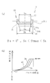
- FIG. 11B shows the flow characteristics of the three flow control valves 101, ie, the flow control valve 101a, the flow control valve 101b, and the flow control valve 101c, which have different valve opening points (the relationship between the change in flow rate with respect to the pulse application amount). It is a graph showing the image of.
- the horizontal axis of the graph represents the amount of pulses applied to the stepping motor
- the vertical axis of the graph represents the flow rate.
- the origin of the graph represents a complete valve closed state in which the valve seat 140 is seated on the seating portion 140a without applying a pulse to the stepping motor.
- the applied amount of the flow rate control valve 101a reaches the valve opening point and the valve body. Then, the valve body 120 of the flow rate control valve 101b and the valve body 120 of the flow rate control valve 101c begin to rise. Further, when the pulse is continuously applied and the applied amount reaches a predetermined number of pulses that maximizes the opening degree of the valve body 120, the opening points of the individual flow control valves 101 are different, and therefore the clearance 142 in the fully opened state is large. Furthermore, as shown in the circle M, the flow rate control valves 101 also vary with respect to the maximum flow rate.
- An object of the present invention is to provide an electric valve having a small individual difference in maximum flow rate.
- the motor-operated valve of the present invention is The rotary motion of the rotor is converted into a linear motion by screw connection between the male screw member and the female screw member, and the valve body accommodated in the valve body is moved in the axial direction based on the linear motion, and the valve body
- a motor-operated valve that provides a back pressure chamber on the upper side of the valve, and introduces pressure in the valve port into the back pressure chamber
- a valve seat having a characteristic surface that determines a flow rate of clearance formed between the valve body, In the case of assuming a frustum formed between the valve body and the valve seat, including a straight line connecting the shortest distance between the lower peripheral edge of the valve body and the characteristic surface, The minimum flow path area of the valve port is formed smaller than the area of the side surface of the frustum when the valve body is fully open.
- the motor operated valve of the present invention is The rotary motion of the rotor is converted into a linear motion by screw connection between the male screw member and the female screw member, and the valve body accommodated in the valve body is moved in the axial direction based on the linear motion, and the valve body
- a motor-operated valve that provides a back pressure chamber on the upper side of the valve, and introduces pressure in the valve port into the back pressure chamber
- a valve seat having a characteristic surface for determining a flow rate of clearance formed between the valve body and an inner peripheral wall surrounding a lower end of the valve body in a valve closed state;
- the minimum flow path area of the valve port is formed larger than the area of the side surface of the frustum when the valve body is in a fully open state, The minimum flow path area of the annular plane formed between the outer peripheral wall surface of the valve body and the inner
- the motor operated valve of the present invention is The inner peripheral surface of the space in the valve seat is not inclined inwardly upward.
- the individual difference in the maximum flow rate can be reduced.
- FIG. 1 It is sectional drawing of the motor operated valve which concerns on embodiment. It is a principal part expanded sectional view of the motor operated valve shown in FIG. In the motor operated valve concerning an embodiment, it is a perspective view showing a truncated cone formed between a valve element and a characteristic surface of a valve seat member. It is a graph which shows the result of having compared the principal part expanded sectional view of the electrically operated valve which concerns on Example 1, and the flow volume characteristic of three electrically operated valves. It is a graph which shows the result of having compared the principal part expanded sectional view of the electrically operated valve which concerns on the modification of Example 1, and the flow volume characteristic of three electrically operated valves.
- FIG. 3 is a cross-sectional view of a conventional flow control valve disclosed in Japanese Patent Laid-Open No. 2014-35006. It is a graph which shows the image at the time of comparing the principal part expanded sectional view of the conventional flow control valve shown in FIG. 10, and the flow characteristics of three conventional flow control valves. It is a graph which shows the image at the time of comparing the flow characteristics of the principal part expanded sectional view of the conventional flow control valve which concerns on the modification of FIG. 10, and three flow control valves.
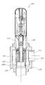
- FIG. 1 is a cross-sectional view showing an electric valve 2 according to an embodiment.
- “upper” or “lower” is defined in the state of FIG. That is, the rotor 4 is positioned above the valve body 17.
- the valve main body 30 is integrally connected by welding or the like below the opening side of a case 60 made of a non-magnetic material and having a cylindrical cup shape.
- the valve main body 30 is a press-molded product manufactured by pressing a stainless steel plate, and has a valve chamber 11 therein.
- the valve body 30 is fixedly mounted with a first pipe joint 12 made of stainless steel or copper that directly communicates with the valve chamber 11.
- a valve seat member 30 ⁇ / b> A in which a valve port 16 having a circular cross section is formed is incorporated in the lower inside of the valve body 30.
- a stainless steel or copper second pipe joint 15 communicating with the valve chamber 11 via the valve port 16 is fixedly attached to the valve seat member 30A.
- Rotating rotor 4 is accommodated in the inner periphery of case 60, and valve shaft 41 is disposed on the shaft core portion of rotor 4 via bush member 33.
- the valve shaft 41 and the rotor 4 coupled by the bush member 33 move integrally in the vertical direction while rotating.
- a male screw 41 a is formed on the outer peripheral surface near the middle portion of the valve shaft 41.
- the valve shaft 41 functions as a male screw member.
- a stator including a yoke, a bobbin, and a coil (not shown) is arranged, and the rotor 4 and the stator constitute a stepping motor.
- a guide support 52 is fixed to the ceiling surface of the case 60.
- the guide support body 52 has a cylindrical portion 53 and an umbrella-shaped portion 54 formed on the upper end side of the cylindrical portion 53, and the whole is integrally formed by press working.
- the umbrella-shaped portion 54 is molded in substantially the same shape as the inside of the top portion of the case 60.
- a cylindrical member 65 that also serves as a guide for the valve shaft 41 is fitted in the cylindrical portion 53 of the guide support 52.
- the cylindrical member 65 is made of a material containing a lubricant or a surface-treated part made of metal or synthetic resin, and rotatably holds the valve shaft 41.
- valve shaft holder 6 that has a function of forming a screw coupling A with the valve shaft 41 and suppressing the inclination of the valve shaft 41 as will be described later. It is fixed to be relatively non-rotatable.
- the valve shaft holder 6 includes an upper cylindrical small diameter portion 6a, a lower cylindrical large diameter portion 6b, a fitting portion 6c accommodated on the inner peripheral side of the valve body 30, and a ring-shaped flange portion 6f. Become.
- the flange portion 6 f of the valve shaft holder 6 is fixed between the upper surface of the flange portion 72 c of the valve element guide member 72 and the case 60 by welding or the like.
- a housing chamber 6h for housing a valve guide 18 (to be described later) is formed inside the valve shaft holder 6.
- a female screw 6d is formed downward from the upper opening 6g of the cylindrical small diameter portion 6a of the valve shaft holder 6 to a predetermined depth.
- the male screw 41a formed on the outer periphery of the valve shaft 41 and the female screw 6d formed on the inner periphery of the cylindrical small diameter portion 6a of the valve shaft holder 6 constitute a screw coupling A.
- a pressure equalizing hole 51 is formed in a side surface of the cylindrical large diameter portion 6b of the valve shaft holder 6, and the pressure equalizing hole 51 allows the valve shaft holder chamber 83 in the cylindrical large diameter portion 6b and the rotor to be formed.
- the accommodation chamber 67 (second back pressure chamber) communicates with it.
- a cylindrical valve guide 18 is disposed below the valve shaft 41 so as to be slidable with respect to the storage chamber 6 h of the valve shaft holder 6.
- the valve guide 18 is bent at a substantially right angle on the ceiling 21 side by press molding.
- a through hole 18 a is formed in the ceiling portion 21.
- a flange 41 b is further formed below the valve shaft 41.
- valve shaft 41 is inserted into the through hole 18a of the valve guide 18 so as to be rotatable with respect to the valve guide 18 and displaceable in the radial direction. It arrange
- valve shaft 41 is inserted through the through hole 18 a and is arranged so that the upper surface of the flange portion 41 b faces the ceiling portion 21 of the valve guide 18.
- the flange 41b is larger in diameter than the through hole 18a of the valve guide 18 so that the valve shaft 41 is prevented from coming off.
- valve shaft 41 and the valve guide 18 are movable in the radial direction with respect to each other, the valve guide 18 and the valve guide 18 and the valve shaft 41 are not required to have a high degree of concentric mounting accuracy with respect to the arrangement positions of the valve shaft holder 6 and the valve shaft 41. Concentricity with the valve body 17 is obtained.
- a washer 70 having a through-hole formed at the center is installed between the ceiling portion 21 of the valve guide 18 and the flange portion 41b of the valve shaft 41.
- the washer 70 is preferably a metal washer having a highly slippery surface, a highly slippery resin washer such as a fluororesin, or a metal washer having a highly slippery resin coating. Further, a compressed valve spring 27 and a spring receiver 35 are accommodated in the valve guide 18.
- valve body guide member 72 that guides the movement of the valve body 17 in the axial direction is disposed inside the valve body 30, and a seal member 48 is interposed between the valve body 17 and the valve body guide member 72. It is intervened.
- valve body 17 a vertical hole 17b and a horizontal conduction hole 17c are formed as pressure equalization paths.
- the pressure in the valve port 16 (in the second pipe joint 15) is guided to the back pressure chamber 28 through the hole 17b and the conduction hole 17c which are pressure equalization paths.
- the valve body guide member 72 is a cylindrical body through which the inside penetrates, and has a flange portion 72c located at the uppermost position, a large diameter portion 72a below the flange portion 72c, and a small diameter portion 72b below the press portion. Is formed by.
- the diameter on the outer peripheral surface side of the large diameter portion 72 a of the valve body guide member 72 is slightly larger than the diameter on the inner peripheral surface side of the valve body 30. That is, by setting the dimensions in this manner, the seal member 48 can be closely locked to the inner peripheral surface of the valve body guide member 72 when the valve body guide member 72 is combined with the valve body 30.
- the seal member 48 is an annular member formed by sandwiching an annular reinforcing plate 48b between an annular packing 48a having an L-shaped cross section.
- leaf springs that constantly urge the annular packing 48a outward are respectively disposed above the annular packing 48a disposed above and below the annular packing 48a disposed below. Is preferred.
- FIG. 2 is an enlarged cross-sectional view of a main part of the motor-operated valve 2 according to the embodiment.
- a characteristic surface 31 that is a surface that determines the flow rate of the clearance 80 between the valve body 17 is formed above the valve port 16.
- the characteristic surface 31 has a mortar shape that inclines outward from the valve port 16 toward the valve body 17.
- the minimum flow path area Sa of the valve port 16 is formed smaller than the cross-sectional area Sn inside the outer diameter of the lower end of the valve body 17.
- a perpendicular line p is drawn from the characteristic surface 31 to the outer peripheral edge of the lower end of the valve body 17.
- the perpendicular p is a straight line connecting the shortest distance between the outer periphery of the lower end of the valve body 17 and the characteristic surface 31.
- a truncated cone 92 is formed between the lower end of the valve body 17 and the valve seat member 30A, as shown in FIG. The side area St of the truncated cone 92 is changed by moving the valve body 17 up and down.
- a predetermined number of pulses that maximizes the opening of the valve body 17 is applied, and the valve body 17 is positioned at a position where the size of the clearance 80 formed between the valve body 17 and the characteristic surface 31 is maximized.
- the side area of the truncated cone 92 when it is set is defined as Stmax (hereinafter referred to as the truncated cone side area Stmax in the fully opened state).
- FIG. 4A is a cross-sectional view illustrating an outline of a main part of the motor-operated valve 2 in the first embodiment.
- the characteristic surface 31 is inclined outwardly from the valve port 16 toward the valve body 17 at a constant inclination angle.
- the minimum flow path area Sa of the valve port 16 is formed to be smaller than the truncated cone side area Stmax in the fully opened state (Sa ⁇ Stmax). In this way, by setting Sa ⁇ Stmax, even when the fluid is introduced from the valve body 17 side and the fluid is led out from the valve port 16, the fluid is also introduced from the valve port 16 side and from the valve body 17 side.
- the flow rate in the fully open state depends on the minimum flow path area Sa of the valve port 16. Therefore, by designing the motor-operated valve 2 such that Sa ⁇ Stmax, the flow rate in the fully opened state is governed only by the minimum flow path area Sa of the valve port 16, and other factors (for example, the motor-operated valve 2 is configured). Variation in processing accuracy of members, variation in assembly accuracy of the motor-operated valve 2, etc.).
- FIG. 4B is a graph showing a situation in which the flow characteristics of the electric valve 2a, the electric valve 2b, and the electric valve 2c are compared.
- the horizontal axis of the graph represents the amount of pulses applied to the stepping motor in the process of opening the valve body 17, and the vertical axis of the graph represents the flow rate.
- the origin of the graph indicates a complete valve closed state in which the valve element 17 is seated on the seating portion 31a in a state where no pulse is applied to the stepping motor.
- the minimum flow path area Sa of the valve port 16 of the motor-operated valve 2a is designed to be smaller than the truncated cone side area Stmax in the fully opened state (Sa ⁇ Stmax). For this reason, even if a pulse is further applied to raise the valve body 17, the flow rate in the fully opened state (maximum flow rate) is only a flow rate corresponding to the minimum flow path area Sa of the valve port 16.
- the motor-operated valve 2b is fully opened, and the motor-operated valve 2c is fully opened.
- the flow rate does not increase even when the valve body 17 is raised by further applying a pulse, and according to the minimum flow path area Sa of the valve port 16. The flow rate is limited.
- the minimum flow path area Sa of the valve port 16 is formed to be smaller than the truncated cone side area Stmax in the fully opened state (Sa ⁇ Stmax), so that the fully opened state is achieved.
- the variation in the flow rate at the time can be reduced, and individual differences between the motor-operated valves can be prevented from occurring in the maximum flow rate.
- the angle of the characteristic surface 31 is changed in the middle to change the rate of increase in the flow rate with respect to the number of pulses. May be greatly inclined outward.
- the characteristic surface 31 is largely inclined outward, it is conceivable that the individual difference in the flow rate for each flow control valve is further increased as shown in FIG.
- the minimum flow path area Sa of the valve port 16 is smaller than the truncated cone side area Stmax in the fully opened state (Sa ⁇ Stmax), as shown in FIG.
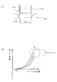
- FIG. 6A is a cross-sectional view illustrating an outline of a main part of the motor-operated valve 2 in the second embodiment.
- the characteristic surface 31 of the valve seat member 30 ⁇ / b> A is inclined outward from the valve port 16 toward the valve body 17 at a constant inclination angle.
- the valve seat member 30A is formed with an inner peripheral wall 32 that rises upward from the upper end of the characteristic surface 31 and surrounds the lower end of the valve body 17 in the valve closed state.
- the motor-operated valve 2 of the second embodiment is designed so that the truncated cone side area Stmax in the fully opened state is smaller than the minimum flow path area Sa of the valve port 16 (Stmax ⁇ Sa).
- the flow rate in the state is not governed by the minimum flow path area Sa of the valve port 16.
- the minimum flow area Ss of the annular plane formed between the outer peripheral wall surface and the inner peripheral wall 32 of the valve element 17 is larger than the truncated cone side area Stmax in the fully opened state. Is also designed to be small (Ss ⁇ Stmax).
- FIG. 6B is a graph showing a situation in which the flow characteristics of the electric valve 2i, the electric valve 2j, and the electric valve 2k are compared.
- FIG. 6B when a pulse is applied to each of the stepping motors of the motorized valve 2i, the motorized valve 2j, and the motorized valve 2k, first, the motorized valve 2i, the motorized valve 2j, and the motorized valve 2k The applied amount reaches the valve opening point in sequence, and the valve body 17 starts to rise.
- the side area St of the truncated cone 92 increases at a constant increase rate according to the inclination angle of the characteristic surface 31.
- the inner peripheral wall 32 restricts the side area St of the truncated cone 92 from expanding, and the side area St of the truncated cone 92 does not increase.
- the minimum flow path area Ss of the annular plane formed between the outer peripheral wall surface and the inner peripheral wall 32 of the valve element 17 is smaller than the truncated cone side area Stmax in the fully opened state. (Ss ⁇ Stmax).
- the flow rate in the fully open state depends on the size of the valve body 17 and the size of the inner peripheral wall 32 and is governed only by the minimum flow path area Ss, so that it is not affected by other factors. Therefore, even if a pulse is further applied to raise the valve body 17, the flow rate in the fully opened state (maximum flow rate) is only a flow rate corresponding to the minimum flow path area Ss of the valve port 16.
- the side area St of the truncated cone 92 of the motor-operated valve 2i becomes the truncated cone-side area Stmax when fully open, and the flow rate of the motor-operated valve 2i is maximized.
- the side area St of the truncated cone 92 of the motor-operated valve 2j becomes the truncated cone-side area Stmax when fully open, and the flow rate of the motor-operated valve 2j is maximized.
- the truncated cone side area Stmax when the truncated cone of the motor-operated valve 2k is fully opened becomes the maximum flow rate of the motor-operated valve 2k.
- the minimum flow passage area Ss of the annular plane formed between the outer peripheral wall surface and the inner peripheral wall 32 of the valve body 17 is set to the truncated cone side area Stmax in the fully opened state.
- the angle of the characteristic surface 31 may be changed in the middle so as to change the rate of increase in the flow rate with respect to the number of pulses.
- the minimum flow path area Ss of the annular plane formed between the outer peripheral wall surface and the inner peripheral wall 32 of the valve body 17 is formed to be smaller than the truncated cone side area Stmax in the fully opened state.
- FIG. 8A is a cross-sectional view illustrating an outline of a main part of the motor-operated valve 2 in the third embodiment.
- the motor operated valve 2 is the motor operated valve 2 in Example 2
- the inner peripheral wall 32 of the valve seat member 30A is inclined slightly outwardly upward.
- ⁇ s ⁇ s> 0 °.
- Example 3 is a modification of Example 2, description about the same structure as Example 2 is abbreviate
- FIG. 8B is a graph showing a situation in which the flow characteristics of the motor-operated valve 2q, the motor-operated valve 2r, and the motor-operated valve 2s having different valve opening points are compared.
- FIG. 8 (b) when a pulse is applied to the stepping motor, the applied amount reaches the valve opening point in the order of the electric valve 2q, the electric valve 2r, and the electric valve 2s, and the valve body 17 rises.
- the inner peripheral wall 32 restricts the side area St of the truncated cone 92 from expanding, and the side area St of the truncated cone 92 does not increase.
- the minimum flow path area Ss of the annular plane formed between the outer peripheral wall surface and the inner peripheral wall 32 of the valve body 17 is designed to be smaller than the truncated cone side area Stmax in the fully opened state. (Ss ⁇ Stmax). For this reason, the flow rate in the fully opened state depends on the dimension of the valve body 17 and the dimension of the inner peripheral wall 32, is governed only by the minimum flow path area Ss, and is not affected by other factors. Therefore, even if a pulse is further applied to raise the valve body 17, the flow rate in the fully opened state (maximum flow rate) is only a flow rate corresponding to the minimum flow path area Ss of the valve port 16.
- the inner peripheral wall 32 of the valve seat member 30A is slightly inclined and the minimum flow path area Ss is not constant. Therefore, as described in the second embodiment, the side area St of the truncated cone 92 is increased. However, the variation in the size of the clearance 80 can be reduced because the increase in the side area St can be significantly suppressed.
- the minimum flow passage area Ss of the annular cross section formed between the outer peripheral wall surface and the inner peripheral wall 32 of the valve body 17 is set to the truncated cone side area Stmax in the fully opened state.
- the difference between the maximum flow rates can be reduced by reducing the variation in the size of the clearance 80 (Ss ⁇ Stmax).
- the valve seat member 30A can be easily injection molded while reducing individual differences in flow rate.
- the angle of the characteristic surface 31 may be changed in the middle so as to change the rate of increase in the flow rate with respect to the number of pulses.
- the minimum flow passage area Ss of the annular cross section formed between the outer peripheral wall surface and the inner peripheral wall 32 of the valve body 17 is formed to be smaller than the truncated cone side area Stmax in the fully opened state.
- the case where the hole 17b and the conduction hole 17c are provided in the valve body 17 as an example of the pressure equalizing path has been described as an example. It does not have to be.
- a piping member that guides the pressure of the valve port 16 to the back pressure chamber 28 may be provided separately.
- the seal member 48 is interposed between the valve body 17 and the valve body guide member 72, and the pressure of the valve port 16 is guided to the back pressure chamber 28 through the pressure equalizing path.
- the motor-operated valve 2 having a structure that cancels out the force due to pressure acting on the body 17 has been described as an example, a motor-operated valve that does not have such a structure may be used.
- the frustum formed between the lower end of the valve body 17 and the characteristic surface 31 may not be a strict frustum.
Landscapes
- Engineering & Computer Science (AREA)
- General Engineering & Computer Science (AREA)
- Mechanical Engineering (AREA)
- Electrically Driven Valve-Operating Means (AREA)
- Lift Valve (AREA)
Abstract
Le problème décrit par la présente invention est de réduire des différences individuelles de débit maximal. La solution selon la présente invention porte sur une soupape actionnée par moteur dans laquelle le mouvement de rotation d'un rotor est converti en un mouvement linéaire par l'intermédiaire du couplage par vissage d'un élément vis mâle et d'un élément vis femelle, un corps de soupape logé dans un corps principal de soupape est déplacé dans la direction axiale sur la base du mouvement linéaire, une chambre de contre-pression est disposée sur le côté supérieur du corps de soupape, et une pression provenant de l'intérieur d'un orifice de soupape est guidée dans la chambre de contre-pression. La soupape actionnée par moteur comporte un siège de soupape ayant une face caractéristique qui détermine le débit du dégagement formé entre le corps de soupape. Une ligne reliant la distance la plus courte entre la face caractéristique et le bord périphérique externe d'extrémité inférieure du corps de soupape est contenue dans une face latérale. Dans un tronc de cône hypothétique formé entre le corps de soupape et le siège de soupape, la surface de passage minimum de l'orifice de soupape est formée de manière à être plus petite que la surface de la face latérale du tronc de cône lorsque le corps de soupape est dans un état complètement ouvert.
Priority Applications (1)
| Application Number | Priority Date | Filing Date | Title |
|---|---|---|---|
| CN201780015206.3A CN108779871B (zh) | 2016-03-29 | 2017-01-13 | 电动阀 |
Applications Claiming Priority (2)
| Application Number | Priority Date | Filing Date | Title |
|---|---|---|---|
| JP2016065702A JP6532836B2 (ja) | 2016-03-29 | 2016-03-29 | 電動弁 |
| JP2016-065702 | 2016-03-29 |
Publications (1)
| Publication Number | Publication Date |
|---|---|
| WO2017168942A1 true WO2017168942A1 (fr) | 2017-10-05 |
Family
ID=59964119
Family Applications (1)
| Application Number | Title | Priority Date | Filing Date |
|---|---|---|---|
| PCT/JP2017/000963 Ceased WO2017168942A1 (fr) | 2016-03-29 | 2017-01-13 | Soupape actionnée par moteur |
Country Status (3)
| Country | Link |
|---|---|
| JP (1) | JP6532836B2 (fr) |
| CN (1) | CN108779871B (fr) |
| WO (1) | WO2017168942A1 (fr) |
Cited By (3)
| Publication number | Priority date | Publication date | Assignee | Title |
|---|---|---|---|---|
| CN107906214A (zh) * | 2017-12-14 | 2018-04-13 | 浙江中宝自控元件有限公司 | 一种流量控制阀 |
| US12072039B2 (en) | 2018-12-20 | 2024-08-27 | Danfoss A/S | Electric expansion valve |
| US12117215B2 (en) | 2018-12-20 | 2024-10-15 | Danfoss A/S | Valve having a motor arranged inside a tube having sections with different diameters |
Families Citing this family (8)
| Publication number | Priority date | Publication date | Assignee | Title |
|---|---|---|---|---|
| CN209196130U (zh) * | 2018-08-02 | 2019-08-02 | 浙江盾安禾田金属有限公司 | 空调及其电子膨胀阀 |
| JP7448947B2 (ja) * | 2020-06-25 | 2024-03-13 | 株式会社レクザム | ニードルバルブ |
| CN114352729B (zh) * | 2020-10-12 | 2022-11-08 | 浙江盾安人工环境股份有限公司 | 流量调节阀 |
| CN114352730A (zh) * | 2020-10-12 | 2022-04-15 | 浙江盾安人工环境股份有限公司 | 流量调节阀 |
| CN115370754B (zh) * | 2021-05-17 | 2025-09-23 | 丹佛斯有限公司 | 流量控制阀 |
| CN115467979B (zh) * | 2021-06-11 | 2025-09-19 | 浙江盾安禾田金属有限公司 | 流量调节阀 |
| WO2022257706A1 (fr) * | 2021-06-11 | 2022-12-15 | 浙江盾安人工环境股份有限公司 | Vanne de régulation de débit |
| JP7440107B2 (ja) * | 2022-01-19 | 2024-02-28 | 株式会社不二工機 | 電動弁 |
Citations (2)
| Publication number | Priority date | Publication date | Assignee | Title |
|---|---|---|---|---|
| JP2000320711A (ja) * | 1999-03-08 | 2000-11-24 | Saginomiya Seisakusho Inc | 電動式コントロールバルブ |
| JP2014081046A (ja) * | 2012-10-17 | 2014-05-08 | Saginomiya Seisakusho Inc | 流量制御弁 |
Family Cites Families (8)
| Publication number | Priority date | Publication date | Assignee | Title |
|---|---|---|---|---|
| JP2006284088A (ja) * | 2005-03-31 | 2006-10-19 | Daikin Ind Ltd | 膨張弁及び冷凍装置 |
| JP4895532B2 (ja) * | 2005-05-27 | 2012-03-14 | 株式会社不二工機 | 電動弁 |
| JP2007309133A (ja) * | 2006-05-16 | 2007-11-29 | Calsonic Kansei Corp | 制御弁 |
| JP2010019378A (ja) * | 2008-07-11 | 2010-01-28 | Denso Corp | 膨張弁 |
| CN202149235U (zh) * | 2011-07-08 | 2012-02-22 | 浙江三花股份有限公司 | 一种电动阀 |
| JP5701825B2 (ja) * | 2012-08-08 | 2015-04-15 | 株式会社鷺宮製作所 | 流量制御弁 |
| JP2014051996A (ja) * | 2012-09-05 | 2014-03-20 | Saginomiya Seisakusho Inc | 流量制御弁 |
| JP6516960B2 (ja) * | 2013-11-08 | 2019-05-22 | 株式会社不二工機 | 電動弁 |
-
2016
- 2016-03-29 JP JP2016065702A patent/JP6532836B2/ja active Active
-
2017
- 2017-01-13 WO PCT/JP2017/000963 patent/WO2017168942A1/fr not_active Ceased
- 2017-01-13 CN CN201780015206.3A patent/CN108779871B/zh active Active
Patent Citations (2)
| Publication number | Priority date | Publication date | Assignee | Title |
|---|---|---|---|---|
| JP2000320711A (ja) * | 1999-03-08 | 2000-11-24 | Saginomiya Seisakusho Inc | 電動式コントロールバルブ |
| JP2014081046A (ja) * | 2012-10-17 | 2014-05-08 | Saginomiya Seisakusho Inc | 流量制御弁 |
Cited By (4)
| Publication number | Priority date | Publication date | Assignee | Title |
|---|---|---|---|---|
| CN107906214A (zh) * | 2017-12-14 | 2018-04-13 | 浙江中宝自控元件有限公司 | 一种流量控制阀 |
| CN107906214B (zh) * | 2017-12-14 | 2023-05-19 | 浙江中宝自控元件有限公司 | 一种流量控制阀 |
| US12072039B2 (en) | 2018-12-20 | 2024-08-27 | Danfoss A/S | Electric expansion valve |
| US12117215B2 (en) | 2018-12-20 | 2024-10-15 | Danfoss A/S | Valve having a motor arranged inside a tube having sections with different diameters |
Also Published As
| Publication number | Publication date |
|---|---|
| CN108779871B (zh) | 2019-11-01 |
| JP6532836B2 (ja) | 2019-06-19 |
| JP2017180569A (ja) | 2017-10-05 |
| CN108779871A (zh) | 2018-11-09 |
Similar Documents
| Publication | Publication Date | Title |
|---|---|---|
| WO2017168942A1 (fr) | Soupape actionnée par moteur | |
| JP6860988B2 (ja) | 電動弁 | |
| JP6392685B2 (ja) | 電動弁 | |
| JP6663981B2 (ja) | 電動弁および冷凍サイクルシステム | |
| JP7113505B2 (ja) | 電動弁 | |
| KR102313777B1 (ko) | 전기 밸브 및 그 제조 방법 | |
| JP6228621B2 (ja) | 電動弁 | |
| JP5047046B2 (ja) | 電動弁 | |
| JP6392686B2 (ja) | 電動弁 | |
| WO2017154347A1 (fr) | Électrovanne | |
| CN108700215A (zh) | 电动阀 | |
| CN112997028A (zh) | 流路切换阀 | |
| JP2021001687A (ja) | 電動弁 | |
| JP6722274B2 (ja) | 電動弁および冷凍サイクルシステム | |
| WO2017168943A1 (fr) | Soupape actionnée par moteur | |
| JP7141484B2 (ja) | 電動弁および冷凍サイクルシステム | |
| JP7333045B2 (ja) | 流量制御弁 | |
| JP6680578B2 (ja) | 電動弁 | |
| WO2018123329A1 (fr) | Soupape motorisée |
Legal Events
| Date | Code | Title | Description |
|---|---|---|---|
| NENP | Non-entry into the national phase |
Ref country code: DE |
|
| 121 | Ep: the epo has been informed by wipo that ep was designated in this application |
Ref document number: 17773492 Country of ref document: EP Kind code of ref document: A1 |
|
| 122 | Ep: pct application non-entry in european phase |
Ref document number: 17773492 Country of ref document: EP Kind code of ref document: A1 |