WO2017169079A1 - Dispositif de traitement d'image, procédé de traitement d'image et élément de capture d'image - Google Patents
Dispositif de traitement d'image, procédé de traitement d'image et élément de capture d'image Download PDFInfo
- Publication number
- WO2017169079A1 WO2017169079A1 PCT/JP2017/003582 JP2017003582W WO2017169079A1 WO 2017169079 A1 WO2017169079 A1 WO 2017169079A1 JP 2017003582 W JP2017003582 W JP 2017003582W WO 2017169079 A1 WO2017169079 A1 WO 2017169079A1
- Authority
- WO
- WIPO (PCT)
- Prior art keywords
- correction
- image
- correction coefficient
- axis
- unit
- Prior art date
- Legal status (The legal status is an assumption and is not a legal conclusion. Google has not performed a legal analysis and makes no representation as to the accuracy of the status listed.)
- Ceased
Links
Images







Classifications
-
- H—ELECTRICITY
- H04—ELECTRIC COMMUNICATION TECHNIQUE
- H04N—PICTORIAL COMMUNICATION, e.g. TELEVISION
- H04N23/00—Cameras or camera modules comprising electronic image sensors; Control thereof
- H04N23/60—Control of cameras or camera modules
-
- G—PHYSICS
- G06—COMPUTING OR CALCULATING; COUNTING
- G06T—IMAGE DATA PROCESSING OR GENERATION, IN GENERAL
- G06T5/00—Image enhancement or restoration
- G06T5/20—Image enhancement or restoration using local operators
-
- H—ELECTRICITY
- H10—SEMICONDUCTOR DEVICES; ELECTRIC SOLID-STATE DEVICES NOT OTHERWISE PROVIDED FOR
- H10F—INORGANIC SEMICONDUCTOR DEVICES SENSITIVE TO INFRARED RADIATION, LIGHT, ELECTROMAGNETIC RADIATION OF SHORTER WAVELENGTH OR CORPUSCULAR RADIATION
- H10F99/00—Subject matter not provided for in other groups of this subclass
Definitions
- the present disclosure relates to an image processing device that performs image correction, an image processing method, and an imaging device.
- Patent Documents 1 and 2 In the field of imaging devices such as digital cameras, techniques for correcting an image (correcting image blur) according to the image height dependency of the lens and MTF characteristics have been proposed (for example, Patent Documents 1 and 2).
- Patent Document 2 discloses a technique in which a user performs correction using a parameter set prepared in advance using software. However, even in this technique, the above-described variation in resolution occurs. In some cases, sufficient correction cannot be performed. This leads to image quality degradation.
- An image processing apparatus includes two or more correction coefficients corresponding to the position coordinates of a correction target pixel among a plurality of correction coefficients associated with each of a first axis and a second axis that intersect each other.
- An acquisition unit that acquires a correction coefficient and a correction unit that performs an image correction process using the correction coefficient acquired by the acquisition unit are provided.
- two or more correction coefficients corresponding to each of the first axis and the second axis intersecting each other are selected according to the position coordinates of the correction target pixel.
- a correction coefficient is acquired, and an image correction process is performed using the acquired correction coefficient.
- An image sensor includes a pixel unit including a plurality of pixels and a signal processing unit that performs signal processing on an image obtained from the pixel unit.
- a signal processing unit that acquires two or more correction coefficients according to the position coordinates of the correction target pixel from a plurality of correction coefficients associated with the first axis and the second axis that intersect with each other;
- a correction unit that performs an image correction process using the correction coefficient acquired by the acquisition unit.
- the position of the correction target pixel from among a plurality of correction coefficients associated with the first axis and the second axis that intersect each other. Two or more correction coefficients are acquired according to the coordinates, and image correction processing is performed using the acquired correction coefficients. Thus, correction can be performed using a correction coefficient optimized according to the position coordinates of the pixel.
- the position of the correction target pixel from among a plurality of correction coefficients associated with the first axis and the second axis that intersect each other. Two or more correction coefficients are acquired according to the coordinates, and image correction processing is performed using the acquired correction coefficients. As a result, a sufficient correction effect can be obtained even when resolution variations occur due to lens manufacturing errors or the like using the optimized correction coefficient. Therefore, even when the lens resolution varies, the image quality deterioration can be suppressed.
- FIG. 4B is a schematic diagram illustrating an example of a correction coefficient of the correction target pixel illustrated in FIG. 4A. It is a schematic diagram showing an example of a correction target pixel (B pixel).
- FIG. 4B is a schematic diagram illustrating an example of a correction coefficient of the correction target pixel illustrated in FIG. 4A. It is a schematic diagram showing an example of a correction target pixel (B pixel).
- 5B is a schematic diagram illustrating an example of a correction coefficient of the correction target pixel illustrated in FIG. 5A. It is a schematic diagram showing a correspondence with a correction coefficient, an image height, and an effective pixel area. It is a characteristic view showing MTF data for explaining setting of an image height position. It is a schematic diagram for demonstrating the MTF data shown in FIG. It is a schematic diagram for demonstrating an example of a correction coefficient blend process (interpolation process). It is a figure showing the example of functional composition in the case of performing friend processing after pixel value amendment. It is a schematic diagram showing the correspondence between the correction coefficient according to Modification 1 and the image height and effective pixel area.
- FIG. 1 illustrates a functional configuration of an imaging device (imaging device 1) according to an embodiment of the present disclosure together with a lens (lens 30).
- the imaging device 1 is an image sensor such as a charge coupled device image sensor (CCD) or a complementary metal oxide semiconductor (CMOS) image sensor, and is applied to, for example, a still camera or a video camera.
- the image sensor 1 is a signal that performs various signal processing including image correction processing on the pixel unit 10 that receives the passing light L of the lens 30 and the image signal (imaging signal D0) output from the pixel unit 10, for example.
- a processing unit 20 includes a control unit that drives and controls each unit of the pixel unit and the signal processing unit, and a memory.
- the pixel unit 10 includes, for example, a plurality of pixels, for example, R (red), G (green), and B (blue) pixels (sub-pixels) arranged two-dimensionally in the effective pixel region.
- Each of the R, G, and B pixels has an RGB array 10a made of, for example, a Bayer array.
- the pixel unit 10 is provided with a color filter having an RGB array 10a.
- the present disclosure is configured to have an array other than RGB, for example, an RGBW array including R, G, B, and W (white). It can also be applied to.
- the pixel unit 10 may have, for example, an array of Y (yellow), C (cyan), M (magenta), and the like. The present disclosure can be applied to color arrangements other than the arrangements exemplified here.
- any of the RGB color lights is received in units of pixels via the lens 30, and an electrical signal corresponding to the received light signal intensity is generated by photoelectric conversion.
- a mosaic image composed of three types of RGB spectra is obtained by the pixel unit 10.
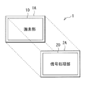
- the pixel unit 10 and the signal processing unit 20 are stacked, for example, as schematically shown in FIG.
- the imaging element 1 has a structure (so-called stacked type element) in which a substrate 1A on which a pixel unit 10 is formed and a substrate 2A on which a signal processing unit 20 is stacked (bonded) one above the other. Structure).
- the “signal processing unit 20” in the present embodiment corresponds to a specific example of the “image processing apparatus” in the present disclosure.
- the “image processing method” of the present disclosure is embodied by the configuration and operation of the image processing apparatus (signal processing unit 20), and thus description thereof is omitted.
- the configuration in which the signal processing unit 20 is provided in the image sensor 1 will be described as an example.
- the image processing apparatus of the present disclosure is applied to such an image sensor 1.
- the apparatus is not limited to the lens 30 and the pixel unit 10, and may be a personal computer (PC) or the like.
- the configuration in addition to the configuration of the signal processing unit 20 illustrated in FIG. 1, the configuration further includes an interface unit to which imaging data is input and a memory in which the input imaging data is stored.
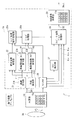
- the signal processing unit 20 includes, for example, a position coordinate calculation unit 21 (a distance calculation unit 21A and an angle calculation unit 21B), a correction coefficient acquisition unit 22, an image height coefficient calculation unit 23A, a quadrant coefficient calculation unit 23B, and a correction A coefficient blend processing unit 24, a lens aberration correction processing unit 25, a line memory 26, an edge detection unit 27, an edge / flat part blend processing unit 28, and an RGB signal processing unit 29 are provided.
- the correction coefficient acquisition unit 22 of the present embodiment corresponds to a specific example of the “acquisition unit” of the present disclosure
- the correction coefficient blend processing unit 24 and the lens aberration correction processing unit 25 correspond to the “correction unit of the present disclosure.
- the correction coefficient blend processing unit 24 corresponds to a specific example of the “correction coefficient calculation unit” of the present disclosure
- the lens aberration correction processing unit 25 corresponds to a specific example of the “correction processing unit” of the present disclosure.
- the position coordinate calculation unit 21 includes, for example, a distance calculation unit 21A and an angle calculation unit 21B. Based on the xy address indicating the coordinate position of each pixel associated with the pixel value of each pixel of the pixel unit 10, The position coordinates of the correction target pixel (hereinafter referred to as pixel Pt) are detected.
- the distance calculation unit 21A calculates the distance of the pixel Pt (the distance r from the optical center, the distance corresponding to the image height). Information on the calculated distance r is supplied to the correction coefficient acquisition unit 22 and the image height coefficient calculation unit 23A, respectively.
- the angle calculation unit 21B calculates a quadrant position (angle d) in the image area of the pixel Pt. Information about the calculated angle d is supplied to the correction coefficient acquisition unit 22 and the quadrant coefficient calculation unit 23B, respectively.
- the correction coefficient acquisition unit 22 selects two or more correction coefficients (Fr, Fg, Fb) from among a plurality of correction coefficients (Fr, Fg, Fb) according to the position coordinates (distance r, angle d) of the pixel Pt calculated by the position coordinate calculation unit 21.
- a correction coefficient (correction coefficient group Fgrp) is selected (acquired).
- Each of the correction coefficients Fr, Fg, and Fb is composed of, for example, a plurality of filter coefficients.
- Information on the acquired correction coefficient group Fgrp is supplied to the correction coefficient blend processing unit 24.
- correction coefficients Fr, Fg, and Fb are set for each color of R, G, and B, respectively, and may be held in the imaging device 1 in advance or may be input from the outside. Details of these correction coefficients Fr, Fg, and Fb will be described later.
- the image height coefficient calculation unit 23A calculates a coefficient (Ar) used in blending processing (interpolation processing) between image heights based on the distance r calculated by the distance calculation unit 21A. Information regarding the calculated coefficient Ar is supplied to the correction coefficient blend processing unit 24.
- the quadrant coefficient calculation unit 23B calculates a coefficient (Ad) used in the blending process (interpolation process) between quadrants based on the angle d calculated by the angle calculation unit 21B.
- Information about the calculated coefficient Ad is supplied to the correction coefficient blend processing unit 24.
- the correction coefficient blend processing unit 24 performs a process of generating a correction coefficient (correction coefficient F1) for the pixel Pt using the correction coefficient group Fgrp acquired by the correction coefficient acquisition unit 22.
- the processing unit generates the correction coefficient F1 for the pixel Pt at the position (image point) where the correction coefficients Fr, Fg, and Fb are not associated with each other by interpolation.
- an interpolation process using each correction coefficient constituting the correction coefficient group Fgrp, the coefficient Ar calculated by the inter-image height coefficient calculation unit 23A, and the coefficient Ad calculated by the inter-quadrant coefficient calculation unit 23B.
- the correction coefficient F1 of the pixel Pt is calculated by (blending processing).
- the correction coefficient F1 is calculated for each RGB color. Information about the calculated correction coefficient F1 is supplied to the lens aberration correction processing unit 25.
- the lens aberration correction processing unit 25 uses correction coefficients F1 (specifically, correction coefficients F1r, F1g, and F1b for each color) for each color signal (Rin, Gin, Bin) input from the line memory 26. Correction processing is performed, and the corrected image signal D1 (Rd, Gd, Bd) is calculated. The calculated image signal D1 is supplied to the edge / flat portion blend processing unit.
- the lens aberration correction processing unit 25 can perform, for example, a process for correcting image blur, particularly a correction process in consideration of aberration variations depending on the position coordinates (image height and quadrant position) of the pixel Pt.
- the line memory 26 temporarily holds the pixel signal output from the pixel unit 10.
- the line memory 26 is configured to store pixel values for seven horizontal lines of the pixel unit 10 and sequentially output seven horizontal line data in parallel.
- the output destinations are the lens aberration correction processing unit 25, the edge detection unit 27, and the edge / flat portion blend processing unit. Imaging data having the RGB array 10a is output in units of 7 lines to each of these processing units.
- the line memory 26 is described as outputting in units of 7 lines, but this is not particularly limited, but a correction coefficient (filter) described later corresponds to, for example, 7 ⁇ 7 pixels. This is an example of a case. For this reason, when the correction coefficient corresponds to the number of pixels other than 7 ⁇ 7 pixels, the line memory 26 can store and output in units of lines corresponding to the number of pixels of the correction coefficient. It is good to be done.
- the edge detection unit 27 Based on the output signal from the line memory 26, the edge detection unit 27 generates information related to edges in the image (including, for example, the edge direction and the edge strength) and outputs the information to the edge / flat part blend processing unit 28. Specifically, for example, the flatness (Weightflat) calculated from the pixel information of 7 ⁇ 7 pixels is calculated based on the processing target pixel (the center pixel of the 7 ⁇ 7 pixels), and the edge / flat portion blending process is performed. To the unit 28. As the flatness calculation process, for example, a process similar to the process described in JP 2011-55038 A can be used.
- the edge / flat portion blend processing unit 28 includes RGB signals (Rin, Gin, Bin) in the input signal from the line memory 26, edge information output from the edge detection unit 27, and output from the lens aberration correction processing unit 25.
- RGB signals Rosin, Gin, Bin
- the image signal D1 (Rd, Gd, Bd) to be generated, the image signal D2 after the correction process considering the edge information is generated and output to the RGB signal processing unit 29.
- the edge / flat portion blend processing unit 28 is configured to perform lens aberration correction processing according to the edge information calculated by the edge detection unit 27 (for example, flatness calculated from pixel information of 7 ⁇ 7 pixels).
- the weighted average processing of the corrected image signal D1 (Rd, Gd, Bd) output from 25 is executed to calculate the RGB pixel values of the RGB array 10a.
- RGB pixel values are determined according to the following three equations.
- the R, G, and B color signals obtained as the calculation result of this expression are output to the RGB signal processing unit 29.
- the RGB signal processing unit 29 performs signal processing on the signals of the RGB array 11a output from the edge / flat portion blend processing unit 28 as signal processing on the signals of the RGB array (Bayer array) 11a to generate a color image.
- the RGB signal processing unit 29 performs, for example, white balance adjustment processing, demosaic processing, shading processing, RGB color matrix processing, gamma correction processing, and the like to generate a color image.
- the image signal Dout for the color image generated by the RGB signal processing unit 29 is output to the outside or recorded in a memory inside the apparatus.
- a control unit executes control of a series of processes in each of the above processing units.
- a program for executing a series of processes is stored in a memory (not shown), and the control unit executes the program read from the memory and controls the series of processes.
- the memory can be composed of various recording media such as a magnetic disk, an optical disk, and a flash memory.
- the correction coefficients Fr, Fg, and Fb are either stored in advance as lens aberration correction filter coefficients or input from the outside. These correction coefficients Fr, Fg, and Fb can be calculated using, for example, a Wiener filter.
- the winner filter will be briefly described. In the following, three images, an ideal image without blur (original image A1), a blurred photographed image (captured image A2), and a restored image (restored image A3) restored by filter correction processing for the photographed image are represented. Assuming this will be explained.
- the filter that minimizes the square error of the two images of the original image A1 and the restored image A3 is called a least square filter or a Wiener filter.
- the original image A1 is f (x, y)
- the photographed image A2 is g (x, y)
- the degradation function due to lens aberration or camera shake is h (x, y)
- the noise component is n (x, y).
- (x, y) is the pixel position of each image
- f (x, y) to n (x, y) may indicate the pixel value of the coordinate position (x, y) of each image.
- the deterioration function h (x, y) due to lens aberration and camera shake is a fixed value.
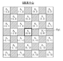
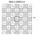
- FIGS. 3A and 3B An example of the Wiener filter corresponding to the above equation (5) is shown in FIGS. 3A and 3B.
- FIG. 3A shows 7 ⁇ 7 pixels centered on the G pixel in the photographed image
- FIG. 3B shows an example of a Wiener filter in which the G pixel at the center of the pixel region in FIG. 3A is the correction target pixel Pt (pixel Pgt). It is shown.
- the photographed image is a RAW image composed of RGB pixels.
- the correction target pixel Pgt is the center G pixel of the 7 ⁇ 7 pixels shown in FIG. 3A.
- the Wiener filter shown in FIG. 3B shows a multiplication coefficient for each of a plurality of G pixels included in a 7 ⁇ 7 pixel.
- a correction pixel value of the central G pixel is calculated by executing a convolution operation that multiplies each coefficient by the pixel value of the G pixel included in the 7 ⁇ 7 pixels and adds the result.
- the pixel value of the G pixel can be corrected by the following formula (6).
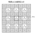
- FIG. 4A shows a 7 ⁇ 7 pixel area centered on the R pixel in the captured image
- FIG. 4B shows the R pixel at the center of the pixel area in FIG. 4A as the correction target pixel Pt (pixel Prt).
- An example of the Wiener filter is shown.
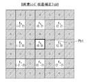
- FIG. 5A shows a 7 ⁇ 7 pixel area centered on the B pixel in the captured image
- FIG. 5B shows a Wiener filter in which the B pixel at the center of the pixel area in FIG. 5A is the correction target pixel Pt (pixel Pbt).
- the correction value is calculated for each of the R pixel and the B pixel in the same manner as in the case of the G pixel.
- lens PSF Point Spread Function
- MTF Modulation Transfer Function
- correction coefficient (Detailed configuration example of correction coefficient)
- a plurality of correction coefficients Fr, Fg, and Fb are associated (set) with each of the first axis and the second axis that intersect each other.
- the following description will be made using the correction coefficient Fg for correcting the G pixel as a representative.
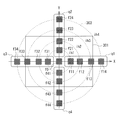
- a plurality of correction coefficients Fg are set for one lens 30. An example is shown in FIG. FIG. 6 shows a correction filter corresponding to 7 ⁇ 7 pixels as an example of the correction coefficient.
- a plurality of correction coefficients Fg are associated with each of the X axis and the Y axis that are orthogonal to each other, for example.
- four correction coefficients f11 to f14 (coefficient sequence q1) are set in the positive direction on the X axis, and for example, four correction coefficients f31 to f34 (coefficient sequence q3) are set in the negative direction on the X axis.
- four correction coefficients f21 to f24 coefficient sequence q2 are set in the positive direction on the Y axis, and for example, four correction coefficients f41 to f44 (coefficient sequence q4) are set in the negative direction on the Y axis. Is set.
- a correction coefficient f0 is set at the optical center (point where the image height is 0).
- the correction coefficient f11 is set to, for example, the image height ih1 (image point at the position of the image height ih1) closest to the optical axis (close to the optical axis) in the coefficient sequence q1.
- the correction coefficient f12 is set to the image height ih2 next to (one outside) the image height ih1 in the coefficient sequence q1.
- the correction coefficient f13 is set to the image height ih3 next to (one outside) the image height ih2 in the coefficient sequence q1.
- the correction coefficient f14 is set to the image height ih4 next to (one outside) the image height ih3 in the coefficient sequence q1.
- the correction coefficient f21 is set to the image height ih1 in the coefficient sequence q2.
- the correction coefficient f22 is set to the image height ih2 in the coefficient sequence q2.
- the correction coefficient f23 is set to the image height ih3 in the coefficient sequence q2.
- the correction coefficient f24 is set to the image height ih4 in the coefficient sequence q2.
- the correction coefficient f31 is set to the image height ih1 in the coefficient sequence q3.
- the correction coefficient f32 is set to the image height ih2 in the coefficient sequence q3.
- the correction coefficient f33 is set to the image height ih3 in the coefficient sequence q3.
- the correction coefficient f34 is set to the image height ih4 in the coefficient sequence q3.
- the correction coefficient f41 is set to the image height ih1 in the coefficient sequence q4.
- the correction coefficient f42 is set to the image height ih2 in the coefficient sequence q4.
- the correction coefficient f43 is set to the image height ih3 in the coefficient sequence q4.
- the correction coefficient f44 is set to the image height ih4 in the coefficient sequence q4.
- a plurality of correction coefficients Fg are set for each of a plurality of image heights and a plurality of angles (rows on the X axis and the Y axis).
- a plurality of correction coefficients Fg (specifically, correction coefficients f11 to f14, f21 to f24, f31 to 34) are obtained at the position coordinates of the four image heights and the four angular directions. , F41 to f44) are set.
- These correction coefficients Fg can be calculated by a method using a Wiener filter as described above.
- two or more correction coefficients are acquired according to the position coordinates of the pixel Pt from the plurality of correction coefficients Fg associated on two axes in this way. It has become.
- correction coefficients Fr and Fb and a plurality of correction coefficients Fr and Fb are associated with each other on two axes (first axis and second axis).
- a plurality of correction coefficients need only be associated with two intersecting axes, and these two axes do not necessarily have to be orthogonal (may be oblique).
- two axes may be arranged along the diagonal line of the effective pixel region 301.
- the correction coefficients Fr, Fg, and Fb are calculated, for example, in the manufacturing process of the lens 30 or the manufacturing process of the camera module, and are held in association with the lens 30.
- the housing portion of the lens 30 has a holding function such as a memory, and correction coefficient information is held by the holding function.
- the correction coefficients Fr, Fg, and Fb are supplied from the lens 30 side outside the signal processing unit 20.
- the correction coefficients Fr, Fg, and Fb may be held in the signal processing unit 20 in advance.
- the correction coefficient is calculated for each lens 30 and is stored in the signal processing unit 20 in advance or input from the outside.
- the set image height intervals can be equal intervals, and the intervals may be constant regardless of lens characteristics.
- a characteristic image height image height 0 to 4
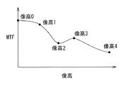
- FIGS. 7 and 8 are diagrams showing MTF data with respect to image height.
- FIG. 8 also shows the image circle 303 and the effective pixel region 301.
- the MTF data changes depending on the image height. Therefore, an image height at an image point with a relatively large degree of change is selected, and a correction coefficient is calculated at the selected image height.
- the image height 0 is selected as the center position of the lens.
- the image height 2 is selected because it is the image height at the point where the MTF data falls. Since the distance between the image height 0 and the image height 2 is separated, the image height 1 is selected as the image height at the approximate center.
- Image height 3 is selected because it is a turning point where the MTF data once lowered at image height 2 rises again and falls again.
- Image height 4 is selected as the end of the lens.
- MTF data or PSF data may be acquired from a plurality of positions on the lens 30 corresponding to these image heights 0 to 4, and the correction coefficient may be calculated by the processing as described above.
- the image height at which the correction coefficient is calculated may be the image height at the image point that is the inflection point in the MTF data.
- the image height at the position may be selected.
- the image height may be added so as to be an appropriate interval.
- MTF data for image height may vary from lens to lens. Therefore, it is desirable that data is acquired for each lens, an image height is selected, and a lens aberration correction filter coefficient is calculated. Lens aberration correction filter coefficients corresponding to different characteristics for each lens can be calculated, and correction processing can be performed with higher accuracy.
- the light beam that has passed through the lens 30 enters the pixel unit 10, whereby a pixel signal is obtained for each pixel by photoelectric conversion.
- the pixel unit 10 acquires R, G, B color RAW data corresponding to the RGB array 10a as the imaging signal D0.
- the obtained imaging signal D0 is output to the signal processing unit 20.
- the signal processing unit 20 performs image correction processing based on the input imaging signal D0. Specifically, first, the position coordinate calculation unit 21 calculates the position coordinate of the pixel Pt to be corrected based on the xy address indicating the coordinate position of each pixel associated with the pixel value of each pixel of the pixel unit 10. To detect. Specifically, the distance calculation unit 21A calculates the distance r of the pixel Pt. Information on the calculated distance r is output to each of the correction coefficient acquisition unit 22 and the image height coefficient calculation unit 23A. Further, the angle calculation unit 21B calculates the quadrant position (angle d) in the image area of the pixel Pt. Information about the calculated angle d is output to the correction coefficient acquisition unit 22 and the quadrant coefficient calculation unit 23B, respectively.
- the correction coefficient acquisition unit 22 selects two or more correction coefficients from a plurality of correction coefficients (here, the correction coefficient Fg is taken as an example) according to the input position coordinates (distance r, angle d) of the pixel Pt. (Correction coefficient group Fgrp) is selected (obtained). Information on the acquired correction coefficient group Fgrp is supplied to the correction coefficient blend processing unit 24.
- the inter-image height coefficient calculation unit 23A calculates a coefficient Ar used in the blending process (interpolation process) between the image heights based on the input distance r. Information about the calculated coefficient Ar is output to the correction coefficient blend processing unit 24.
- the quadrant coefficient calculation unit 23B calculates a coefficient Ad used in the blend process (interpolation process) between quadrants based on the input angle d. Information about the calculated coefficient Ad is output to the correction coefficient blend processing unit 24.
- the correction coefficient blend processing unit 24 generates the correction coefficient F1 of the pixel Pt by interpolation processing using the input correction coefficient group Fgrp. Specifically, the correction coefficient F1 (first correction coefficient) of the pixel Pt is calculated by interpolation processing (blend processing) using the correction coefficients constituting the correction coefficient group Fgrp and the coefficients Ar and Ad.
- FIG. 9 shows an example of correction coefficient blending processing.
- interpolation processing is performed between angles (between quadrants and axes) and between image heights in the XY plane.
- the correction coefficient F1 of the center pixel Pt of 7 ⁇ 7 pixels is calculated by interpolation processing using a correction coefficient group Fgrp including two or more correction coefficients Fg and the coefficients Ar and Ad.
- the image height ih n corresponds to any one of the image heights ih1 to ih4 (image height position) shown in FIG. 6, for example, and the image height ih n + 1 is 1 of the image height ih n . It corresponds to the outer image height.
- the pixel Pt will be described as a G pixel located in the first quadrant in the XY plane.
- the correction coefficient acquisition unit 22 uses a plurality of correction coefficients Fg (correction coefficients f11 to f14, f21 to f24, f31 to 34, and f41 to f44 shown in FIG.
- Two or more appropriate correction coefficients Fg are selected (acquired) according to the distance r and the angle d).
- the correction coefficient group Fgrp includes, for example, two correction coefficients F0 n and F0 n + 1 (any two correction coefficients in the coefficient sequence q1 illustrated in FIG.
- the correction coefficient blend process is performed from the following equation (6) by linear calculation. Thereby, the blending process between quadrants (between axes) is performed on the image height ih n , and the correction coefficient F2 (second correction coefficient) is calculated.
- linearity is calculated using correction coefficients F0 n + 1 and F90 n + 1 associated with the image height ih n + 1 and a coefficient Ad (0 ⁇ Ad ⁇ 1) calculated based on the angle d.
- the correction coefficient blending process is performed from the following equation (7) by calculation. Thereby, a blending process between quadrants (between axes) is performed on the image height ih n + 1 , and a correction coefficient F3 (third correction coefficient) is calculated.
- F3 (1-Ad) ⁇ F0 n + 1 + Ad ⁇ F90 n + 1 (7)
- these correction coefficients F2 and F3 are obtained from the following equation (8) by linear calculation using a coefficient Ar (0 ⁇ Ar ⁇ 1) calculated based on the distance r (distance from the optical center).
- the correction coefficient blending process is performed. Thereby, the blending process between the image heights is performed, and the correction coefficient F1 of the pixel Pt at the position of distance r and angle d is calculated. That is, the correction coefficient of the pixel Pt is optimized.
- F1 (1-Ar) ⁇ F2 + Ad ⁇ F3 (8)
- the lens aberration correction processing unit 25 corrects the pixel value in the pixel Pt using the correction coefficient F1 (as an example) for each color signal (Rin, Gin, Bin) input from the line memory 26.
- Lens aberration correction processing Specifically, when the correction coefficient F1 corresponds to 7 ⁇ 7 pixels, a calculation process of multiplying and adding the 7 ⁇ 7 pixels is performed, and the pixel of the center pixel Pt is executed. Correct the value. Assuming that the pixel value of the pixel Pt at the distance r is Pr, the pixel value Pr1 after lens aberration correction is calculated by the following equation (9).
- the correction processing is performed on the pixel values after blending (interpolating) correction coefficients between quadrants and between image heights.
- the blend processing (interpolation processing) It may be performed after the correction.
- FIG. 10 shows a functional block configuration in that case.
- the lens aberration correction processing unit 25a corrects the pixel value of the pixel Pt to be corrected using a plurality of correction coefficients associated on two axes.
- the blend processing unit 26a may perform interpolation processing between quadrants and between image heights based on the corrected pixel values. Further, the order in which the blending process and the correction process are performed may be determined according to the data amount of the correction coefficient.
- the image signal D1 (Rd, Gd, Bd) after the correction processing by the lens aberration correction processing unit 25 is output to the edge / flat portion blend processing unit.
- the edge / flat portion blend processing unit 28 receives RGB signals (Rin, Gin, Bin) input from the line memory 26, edge information input from the edge detection unit 27, and lens aberration correction processing unit 25. Using the image signal D1 (Rd, Gd, Bd), an image signal D2 after correction processing in consideration of edge information is generated. Specifically, the edge / flat portion blend processing unit 28 is configured to perform lens aberration correction processing according to the edge information calculated by the edge detection unit 27 (for example, flatness calculated from pixel information of 7 ⁇ 7 pixels). The weighted average processing of the corrected image signal D1 (Rd, Gd, Bd) output from 25 is executed to calculate the RGB pixel values in the RGB array 10a. Specifically, RGB pixel values are determined according to the following three equations.
- the R, G, and B color signals obtained as the calculation result of this expression are output to the RGB signal processing unit 29.
- the generated image signal D2 is output to the RGB signal processing unit 29.
- the RGB signal processing unit 29 performs signal processing on the input RGB array (Bayer array) signal, for example, white balance adjustment processing, demosaic processing, shading processing, RGB color matrix processing, gamma correction processing, and the like to generate a color image. Generate. An image signal Dout for the generated color image is output to the outside or recorded in a memory inside the apparatus.
- the position coordinates of the pixel Pt to be corrected are selected from among a plurality of correction coefficients associated with the first axis and the second axis (X axis, Y axis) that intersect each other. Two or more correction coefficients are acquired according to (distance r, angle d), and image correction processing is performed using the acquired correction coefficients. Thereby, the correction coefficient can be optimized according to the position coordinates of the pixel Pt.
- the generated blur differs depending on the characteristics of the lens 30 and the like. For example, as the image height (distance from the optical center) increases, the blur of the image due to lens aberration increases. Further, due to a manufacturing error of the lens and the like, not only the image height of the lens but also a variation in aberration occurs in each region (quadrant) in the XY plane orthogonal to the optical axis, resulting in a variation in resolution.
- the degree of blurring of the lens 30 is different and is often not isotropic. This is caused by, for example, a lens manufacturing error. If the resolution of the lens 30 varies, even if correction processing is performed, a location where correction is insufficient or an overcorrected location occurs depending on the pixel position, leading to image quality degradation.
- a pixel to be corrected is selected from a plurality of correction coefficients associated with the first axis and the second axis (X axis and Y axis) that intersect each other.
- Two or more correction coefficients are acquired according to the position coordinates (distance r, angle d) of Pt, and image correction processing is performed using the acquired correction coefficients.
- the correction coefficient can be optimized, and a sufficient correction effect can be obtained even when the resolution varies due to a lens manufacturing error or the like. Therefore, even when the lens resolution varies, the image quality deterioration can be suppressed.
- FIG. 11 is a schematic diagram illustrating a correspondence between a correction coefficient (any one of Fg, Fr, and Fb) according to the first modification, an image height, and an effective pixel area.
- a correction coefficient any one of Fg, Fr, and Fb
- FIG. 6 the configuration in which the coefficient sequences q1 to q4 are arranged along the X axis and the Y axis has been exemplified.
- the coefficient sequences q1 to q4 are arranged.
- q4 may be associated with two axes rotated 45 ° counterclockwise from the X axis and the Y axis, respectively. In this case, it is effective when the lens blur occurs along an oblique direction.
- the rotation angle of the shaft is not limited to 45 °, and can be set in a range from 0 ° to 90 ° depending on a region where a lens blur occurs.
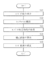
- FIG. 12 shows a flow of correction coefficient calculation and signal processing according to the second modification.
- the correction coefficients Fr, Fg, and Fb are calculated in the manufacturing process of the lens 30 or the manufacturing process of the camera module, and are stored in the circuit in advance as calibration information, or are externally (lens 30 ).
- the signal processing (image processing) of the present disclosure can also be applied when there is no calibration information regarding such a lens 30 (for example, when the lens 30 is an old lens).
- the correction coefficient may be input by the user. Specifically, as shown in FIG. 12, after the lens 30 is attached to the camera body (step S21), a test chart (test pattern) is photographed by the image sensor 1 (step S22). Subsequently, lens aberration characteristics (for example, PSF data or MTF data) are acquired from the captured image (step S23). A correction coefficient may be calculated based on the acquired lens aberration characteristic (step S24), and the lens aberration may be corrected using this correction coefficient.
- lens aberration characteristics for example, PSF data or MTF data
- the correction coefficient may be calculated not when the lens 30 is manufactured but when the camera is used. In this case, an old lens having no calibration information can be used as the lens 30. In addition, it is possible to appropriately update the correction coefficient in response to a change in the usage environment or aging of the lens 30. Further, when the lens 30 is replaceable with respect to the camera body, it is possible to cope with the case where the lens 30 is replaced with another lens.
- the technology according to the present disclosure can be applied to various products.
- the technology according to the present disclosure is realized as a device that is mounted on any type of mobile body such as an automobile, an electric vehicle, a hybrid electric vehicle, a motorcycle, a bicycle, personal mobility, an airplane, a drone, a ship, and a robot. May be.
- FIG. 13 is a block diagram illustrating a schematic configuration example of a vehicle control system that is an example of a mobile control system to which the technology according to the present disclosure can be applied.
- the vehicle control system 12000 includes a plurality of electronic control units connected via a communication network 12001.
- the vehicle control system 12000 includes a drive system control unit 12010, a body system control unit 12020, a vehicle exterior information detection unit 12030, a vehicle interior information detection unit 12040, and an integrated control unit 12050.
- a microcomputer 12051, a sound image output unit 12052, and an in-vehicle network I / F (Interface) 12053 are illustrated as a functional configuration of the integrated control unit 12050.
- the drive system control unit 12010 controls the operation of the device related to the drive system of the vehicle according to various programs.
- the drive system control unit 12010 includes a driving force generator for generating a driving force of a vehicle such as an internal combustion engine or a driving motor, a driving force transmission mechanism for transmitting the driving force to wheels, and a steering angle of the vehicle. It functions as a control device such as a steering mechanism that adjusts and a braking device that generates a braking force of the vehicle.
- the body system control unit 12020 controls the operation of various devices mounted on the vehicle body according to various programs.
- the body system control unit 12020 functions as a keyless entry system, a smart key system, a power window device, or a control device for various lamps such as a headlamp, a back lamp, a brake lamp, a blinker, or a fog lamp.
- the body control unit 12020 can be input with radio waves transmitted from a portable device that substitutes for a key or signals from various switches.
- the body system control unit 12020 receives input of these radio waves or signals, and controls a door lock device, a power window device, a lamp, and the like of the vehicle.
- the vehicle outside information detection unit 12030 detects information outside the vehicle on which the vehicle control system 12000 is mounted.
- the imaging unit 12031 is connected to the vehicle exterior information detection unit 12030.
- the vehicle exterior information detection unit 12030 causes the imaging unit 12031 to capture an image outside the vehicle and receives the captured image.
- the vehicle outside information detection unit 12030 may perform an object detection process or a distance detection process such as a person, a car, an obstacle, a sign, or a character on a road surface based on the received image.
- the imaging unit 12031 is an optical sensor that receives light and outputs an electrical signal corresponding to the amount of received light.
- the imaging unit 12031 can output an electrical signal as an image, or can output it as distance measurement information. Further, the light received by the imaging unit 12031 may be visible light or invisible light such as infrared rays.
- the vehicle interior information detection unit 12040 detects vehicle interior information.
- a driver state detection unit 12041 that detects a driver's state is connected to the in-vehicle information detection unit 12040.
- the driver state detection unit 12041 includes, for example, a camera that images the driver, and the vehicle interior information detection unit 12040 determines the degree of fatigue or concentration of the driver based on the detection information input from the driver state detection unit 12041. It may be calculated or it may be determined whether the driver is asleep.
- the microcomputer 12051 calculates a control target value of the driving force generator, the steering mechanism, or the braking device based on the information inside / outside the vehicle acquired by the vehicle outside information detection unit 12030 or the vehicle interior information detection unit 12040, and the drive system control unit A control command can be output to 12010.
- the microcomputer 12051 realizes ADAS (Advanced Driver Assistance System) functions including vehicle collision avoidance or impact mitigation, following traveling based on inter-vehicle distance, vehicle speed maintenance traveling, vehicle collision warning, or vehicle lane departure warning. It is possible to perform cooperative control for the purpose.
- ADAS Advanced Driver Assistance System
- the microcomputer 12051 controls the driving force generator, the steering mechanism, the braking device, and the like based on the information around the vehicle acquired by the vehicle exterior information detection unit 12030 or the vehicle interior information detection unit 12040. It is possible to perform cooperative control for the purpose of automatic driving that autonomously travels without depending on the operation.
- the microcomputer 12051 can output a control command to the body system control unit 12030 based on information outside the vehicle acquired by the vehicle outside information detection unit 12030.
- the microcomputer 12051 controls the headlamp according to the position of the preceding vehicle or the oncoming vehicle detected by the outside information detection unit 12030, and performs cooperative control for the purpose of anti-glare, such as switching from a high beam to a low beam. It can be carried out.
- the sound image output unit 12052 transmits an output signal of at least one of sound and image to an output device capable of visually or audibly notifying information to a vehicle occupant or the outside of the vehicle.
- an audio speaker 12061, a display unit 12062, and an instrument panel 12063 are illustrated as output devices.
- the display unit 12062 may include at least one of an on-board display and a head-up display, for example.
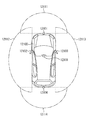
- FIG. 14 is a diagram illustrating an example of an installation position of the imaging unit 12031.
- the imaging unit 12031 includes imaging units 12101, 12102, 12103, 12104, and 12105.
- the imaging units 12101, 12102, 12103, 12104, and 12105 are provided, for example, at positions such as a front nose, a side mirror, a rear bumper, a back door, and an upper part of a windshield in the vehicle interior of the vehicle 12100.
- the imaging unit 12101 provided in the front nose and the imaging unit 12105 provided in the upper part of the windshield in the vehicle interior mainly acquire an image in front of the vehicle 12100.
- the imaging units 12102 and 12103 provided in the side mirror mainly acquire an image of the side of the vehicle 12100.
- the imaging unit 12104 provided in the rear bumper or the back door mainly acquires an image behind the vehicle 12100.
- the imaging unit 12105 provided on the upper part of the windshield in the passenger compartment is mainly used for detecting a preceding vehicle or a pedestrian, an obstacle, a traffic light, a traffic sign, a lane, or the like.
- FIG. 14 shows an example of the shooting range of the imaging units 12101 to 12104.
- the imaging range 12111 indicates the imaging range of the imaging unit 12101 provided in the front nose
- the imaging ranges 12112 and 12113 indicate the imaging ranges of the imaging units 12102 and 12103 provided in the side mirrors, respectively
- the imaging range 12114 The imaging range of the imaging part 12104 provided in the rear bumper or the back door is shown. For example, by superimposing the image data captured by the imaging units 12101 to 12104, an overhead image when the vehicle 12100 is viewed from above is obtained.
- At least one of the imaging units 12101 to 12104 may have a function of acquiring distance information.
- at least one of the imaging units 12101 to 12104 may be a stereo camera including a plurality of imaging elements, or may be an imaging element having pixels for phase difference detection.
- the microcomputer 12051 based on the distance information obtained from the imaging units 12101 to 12104, the distance to each three-dimensional object in the imaging range 12111 to 12114 and the temporal change in this distance (relative speed with respect to the vehicle 12100).
- a predetermined speed for example, 0 km / h or more
- the microcomputer 12051 can set an inter-vehicle distance to be secured in advance before the preceding vehicle, and can perform automatic brake control (including follow-up stop control), automatic acceleration control (including follow-up start control), and the like.
- automatic brake control including follow-up stop control
- automatic acceleration control including follow-up start control
- cooperative control for the purpose of autonomous driving or the like autonomously traveling without depending on the operation of the driver can be performed.
- the microcomputer 12051 converts the three-dimensional object data related to the three-dimensional object to other three-dimensional objects such as a two-wheeled vehicle, a normal vehicle, a large vehicle, a pedestrian, and a utility pole based on the distance information obtained from the imaging units 12101 to 12104. It can be classified and extracted and used for automatic avoidance of obstacles.
- the microcomputer 12051 identifies obstacles around the vehicle 12100 as obstacles that are visible to the driver of the vehicle 12100 and obstacles that are difficult to see.
- the microcomputer 12051 determines the collision risk indicating the risk of collision with each obstacle, and when the collision risk is equal to or higher than the set value and there is a possibility of collision, the microcomputer 12051 is connected via the audio speaker 12061 or the display unit 12062. By outputting an alarm to the driver and performing forced deceleration or avoidance steering via the drive system control unit 12010, driving assistance for collision avoidance can be performed.
- At least one of the imaging units 12101 to 12104 may be an infrared camera that detects infrared rays.
- the microcomputer 12051 can recognize a pedestrian by determining whether a pedestrian is present in the captured images of the imaging units 12101 to 12104. Such pedestrian recognition is, for example, whether or not the user is a pedestrian by performing a pattern matching process on a sequence of feature points indicating the outline of an object and a procedure for extracting feature points in the captured images of the imaging units 12101 to 12104 as infrared cameras. It is carried out by the procedure for determining.
- the audio image output unit 12052 When the microcomputer 12051 determines that there is a pedestrian in the captured images of the imaging units 12101 to 12104 and recognizes the pedestrian, the audio image output unit 12052 has a rectangular contour line for emphasizing the recognized pedestrian.
- the display unit 12062 is controlled so as to be superimposed and displayed.
- voice image output part 12052 may control the display part 12062 so that the icon etc. which show a pedestrian may be displayed on a desired position.
- the present disclosure has been described with reference to the embodiment and its modifications. However, the present disclosure is not limited to the above-described embodiment and the like, and various modifications are possible.
- the series of signal processing described above can be executed by hardware or can be executed by software.
- a series of processing is executed by software
- a program constituting the software is installed in the computer.
- the computer includes, for example, a general-purpose personal computer capable of executing various functions by installing various programs by installing a computer incorporated in dedicated hardware.
- this indication can also take the following structures.
- An acquisition unit that acquires two or more correction coefficients according to the position coordinates of the correction target pixel from among a plurality of correction coefficients associated with each of the first axis and the second axis that intersect each other;
- An image processing apparatus comprising: a correction unit that performs an image correction process using the correction coefficient acquired by the acquisition unit.
- the correction unit is A correction coefficient calculation unit that calculates a first correction coefficient at the position coordinates by an interpolation process using the correction coefficient acquired by the acquisition unit;
- the image processing apparatus according to (1) further including: a correction processing unit that corrects a pixel value corresponding to the position coordinates using the first correction coefficient calculated by the correction coefficient calculation unit.
- the image processing apparatus according to (4), wherein the third correction coefficient is calculated by performing interpolation according to the above.
- (6) In the second interpolation process, after the first interpolation process, The image processing apparatus according to (5), wherein the first correction coefficient is calculated by interpolating the second correction coefficient and the third correction coefficient in accordance with an image height of the position coordinates.
- the correction unit is Correct the pixel value using the correction coefficient acquired by the acquisition unit; The image processing apparatus according to (1), wherein the image is corrected by an interpolation process based on the corrected pixel value.
- the acquisition unit acquires a plurality of correction coefficients associated with the first axis and the second axis for each color, The image processing apparatus according to any one of (1) to (7), wherein the correction unit performs an image correction process using the acquired correction coefficient for each color.
- the image processing apparatus according to any one of (1) to (7), wherein the correction unit performs an image correction process using the acquired correction coefficient for each color.
- the 9 From the plurality of correction coefficients associated with each of the first axis and the second axis intersecting each other, two or more correction coefficients are acquired according to the position coordinates of the correction target pixel, An image processing method for correcting an image using an acquired correction coefficient.
- a first correction coefficient at the position coordinates is calculated by an interpolation process using the acquired correction coefficient, The image processing method according to (9), wherein the pixel value corresponding to the position coordinate is corrected using the calculated first correction coefficient.
- the second interpolation processing is performed based on the image height of the position coordinates before or after the first interpolation processing.
- a pixel portion including a plurality of pixels; A signal processing unit that performs signal processing on an image obtained from the pixel unit, The signal processing unit An acquisition unit that acquires two or more correction coefficients according to the position coordinates of the correction target pixel from among a plurality of correction coefficients associated with each of the first axis and the second axis that intersect each other; An image pickup device comprising: a correction unit that performs correction processing of the image using the correction coefficient acquired by the acquisition unit.
Landscapes
- Engineering & Computer Science (AREA)
- Multimedia (AREA)
- Signal Processing (AREA)
- Physics & Mathematics (AREA)
- General Physics & Mathematics (AREA)
- Theoretical Computer Science (AREA)
- Studio Devices (AREA)
- Solid State Image Pick-Up Elements (AREA)
- Transforming Light Signals Into Electric Signals (AREA)
- Image Processing (AREA)
Abstract
La présente invention concerne un dispositif de traitement d'image qui est pourvu : d'une unité d'acquisition, qui acquiert au moins deux coefficients de correction correspondant aux coordonnées de position d'un pixel qui doit être corrigé, lesdits coefficients de correction étant acquis parmi une pluralité de coefficients de correction associés respectivement à un premier axe et à un second axe, qui se coupent ; et d'une unité de correction qui corrige une image à l'aide des coefficients de correction ainsi acquis par l'unité d'acquisition.
Applications Claiming Priority (2)
| Application Number | Priority Date | Filing Date | Title |
|---|---|---|---|
| JP2016063188A JP2017183775A (ja) | 2016-03-28 | 2016-03-28 | 画像処理装置、画像処理方法および撮像素子 |
| JP2016-063188 | 2016-03-28 |
Publications (1)
| Publication Number | Publication Date |
|---|---|
| WO2017169079A1 true WO2017169079A1 (fr) | 2017-10-05 |
Family
ID=59963796
Family Applications (1)
| Application Number | Title | Priority Date | Filing Date |
|---|---|---|---|
| PCT/JP2017/003582 Ceased WO2017169079A1 (fr) | 2016-03-28 | 2017-02-01 | Dispositif de traitement d'image, procédé de traitement d'image et élément de capture d'image |
Country Status (2)
| Country | Link |
|---|---|
| JP (1) | JP2017183775A (fr) |
| WO (1) | WO2017169079A1 (fr) |
Families Citing this family (1)
| Publication number | Priority date | Publication date | Assignee | Title |
|---|---|---|---|---|
| TWI820194B (zh) | 2018-08-31 | 2023-11-01 | 日商索尼半導體解決方案公司 | 電子機器及固體攝像裝置 |
Citations (5)
| Publication number | Priority date | Publication date | Assignee | Title |
|---|---|---|---|---|
| JP2005341033A (ja) * | 2004-05-25 | 2005-12-08 | Konica Minolta Photo Imaging Inc | 撮像装置及びプログラム |
| JP2014022828A (ja) * | 2012-07-13 | 2014-02-03 | Toshiba Corp | カメラモジュール |
| JP2015109582A (ja) * | 2013-12-05 | 2015-06-11 | 三星電子株式会社Samsung Electronics Co.,Ltd. | 画像処理装置及び画像処理方法 |
| JP2015204471A (ja) * | 2014-04-10 | 2015-11-16 | キヤノン株式会社 | 固体撮像素子その制御方法、電子機器、プログラム、記憶媒体 |
| JP2016005057A (ja) * | 2014-06-16 | 2016-01-12 | 株式会社ソシオネクスト | 画像処理装置、画像処理方法及び撮像装置 |
-
2016
- 2016-03-28 JP JP2016063188A patent/JP2017183775A/ja active Pending
-
2017
- 2017-02-01 WO PCT/JP2017/003582 patent/WO2017169079A1/fr not_active Ceased
Patent Citations (5)
| Publication number | Priority date | Publication date | Assignee | Title |
|---|---|---|---|---|
| JP2005341033A (ja) * | 2004-05-25 | 2005-12-08 | Konica Minolta Photo Imaging Inc | 撮像装置及びプログラム |
| JP2014022828A (ja) * | 2012-07-13 | 2014-02-03 | Toshiba Corp | カメラモジュール |
| JP2015109582A (ja) * | 2013-12-05 | 2015-06-11 | 三星電子株式会社Samsung Electronics Co.,Ltd. | 画像処理装置及び画像処理方法 |
| JP2015204471A (ja) * | 2014-04-10 | 2015-11-16 | キヤノン株式会社 | 固体撮像素子その制御方法、電子機器、プログラム、記憶媒体 |
| JP2016005057A (ja) * | 2014-06-16 | 2016-01-12 | 株式会社ソシオネクスト | 画像処理装置、画像処理方法及び撮像装置 |
Also Published As
| Publication number | Publication date |
|---|---|
| JP2017183775A (ja) | 2017-10-05 |
Similar Documents
| Publication | Publication Date | Title |
|---|---|---|
| JP6724982B2 (ja) | 信号処理装置および撮像装置 | |
| US11605661B2 (en) | Image processing apparatus, image processing method, and solid-state imaging apparatus to detect polarization properties of each color | |
| US11394913B2 (en) | Solid-state imaging element, electronic device, and method for controlling correction of luminance in the solid-state imaging element | |
| CN111480057B (zh) | 图像处理装置、图像处理方法和程序 | |
| US11172173B2 (en) | Image processing device, image processing method, program, and imaging device | |
| CN109644241B (zh) | 图像处理设备和图像处理方法 | |
| US20200185436A1 (en) | Imaging apparatus and imaging method | |
| CN114270798A (zh) | 摄像装置 | |
| CN111345036A (zh) | 图像处理装置、成像装置、驾驶辅助装置、移动体和图像处理方法 | |
| WO2020075357A1 (fr) | Élément d'imagerie à semi-conducteur, dispositif d'imagerie, et procédé de contrôle d'élément d'imagerie à semi-conducteur | |
| US10873732B2 (en) | Imaging device, imaging system, and method of controlling imaging device | |
| WO2017169079A1 (fr) | Dispositif de traitement d'image, procédé de traitement d'image et élément de capture d'image | |
| WO2017149964A1 (fr) | Dispositif de traitement d'image, procédé de traitement d'image, programme informatique et dispositif électronique | |
| CN113170057A (zh) | 摄像部控制装置 | |
| CN119404514A (zh) | 固态成像装置和电子装置 | |
| US20210217146A1 (en) | Image processing apparatus and image processing method | |
| JP7059185B2 (ja) | 画像処理装置、画像処理方法、および撮像装置 | |
| WO2020137503A1 (fr) | Dispositif de traitement d'image | |
| WO2025062831A1 (fr) | Dispositif de traitement d'image, procédé de traitement d'image et programme | |
| WO2022219874A1 (fr) | Dispositif et procédé de traitement de signaux, et programme |
Legal Events
| Date | Code | Title | Description |
|---|---|---|---|
| NENP | Non-entry into the national phase |
Ref country code: DE |
|
| 121 | Ep: the epo has been informed by wipo that ep was designated in this application |
Ref document number: 17773628 Country of ref document: EP Kind code of ref document: A1 |
|
| 122 | Ep: pct application non-entry in european phase |
Ref document number: 17773628 Country of ref document: EP Kind code of ref document: A1 |