WO2017169180A1 - Dispositif d'entraînement de véhicule et véhicule électrique - Google Patents
Dispositif d'entraînement de véhicule et véhicule électrique Download PDFInfo
- Publication number
- WO2017169180A1 WO2017169180A1 PCT/JP2017/005039 JP2017005039W WO2017169180A1 WO 2017169180 A1 WO2017169180 A1 WO 2017169180A1 JP 2017005039 W JP2017005039 W JP 2017005039W WO 2017169180 A1 WO2017169180 A1 WO 2017169180A1
- Authority
- WO
- WIPO (PCT)
- Prior art keywords
- motor
- power
- state
- combustion engine
- internal combustion
- Prior art date
- Legal status (The legal status is an assumption and is not a legal conclusion. Google has not performed a legal analysis and makes no representation as to the accuracy of the status listed.)
- Ceased
Links
Images


Classifications
-
- B—PERFORMING OPERATIONS; TRANSPORTING
- B60—VEHICLES IN GENERAL
- B60W—CONJOINT CONTROL OF VEHICLE SUB-UNITS OF DIFFERENT TYPE OR DIFFERENT FUNCTION; CONTROL SYSTEMS SPECIALLY ADAPTED FOR HYBRID VEHICLES; ROAD VEHICLE DRIVE CONTROL SYSTEMS FOR PURPOSES NOT RELATED TO THE CONTROL OF A PARTICULAR SUB-UNIT
- B60W20/00—Control systems specially adapted for hybrid vehicles
- B60W20/40—Controlling the engagement or disengagement of prime movers, e.g. for transition between prime movers
-
- B—PERFORMING OPERATIONS; TRANSPORTING
- B60—VEHICLES IN GENERAL
- B60K—ARRANGEMENT OR MOUNTING OF PROPULSION UNITS OR OF TRANSMISSIONS IN VEHICLES; ARRANGEMENT OR MOUNTING OF PLURAL DIVERSE PRIME-MOVERS IN VEHICLES; AUXILIARY DRIVES FOR VEHICLES; INSTRUMENTATION OR DASHBOARDS FOR VEHICLES; ARRANGEMENTS IN CONNECTION WITH COOLING, AIR INTAKE, GAS EXHAUST OR FUEL SUPPLY OF PROPULSION UNITS IN VEHICLES
- B60K6/00—Arrangement or mounting of plural diverse prime-movers for mutual or common propulsion, e.g. hybrid propulsion systems comprising electric motors and internal combustion engines
- B60K6/20—Arrangement or mounting of plural diverse prime-movers for mutual or common propulsion, e.g. hybrid propulsion systems comprising electric motors and internal combustion engines the prime-movers consisting of electric motors and internal combustion engines, e.g. HEVs
- B60K6/22—Arrangement or mounting of plural diverse prime-movers for mutual or common propulsion, e.g. hybrid propulsion systems comprising electric motors and internal combustion engines the prime-movers consisting of electric motors and internal combustion engines, e.g. HEVs characterised by apparatus, components or means specially adapted for HEVs
- B60K6/26—Arrangement or mounting of plural diverse prime-movers for mutual or common propulsion, e.g. hybrid propulsion systems comprising electric motors and internal combustion engines the prime-movers consisting of electric motors and internal combustion engines, e.g. HEVs characterised by apparatus, components or means specially adapted for HEVs characterised by the motors or the generators
-
- B—PERFORMING OPERATIONS; TRANSPORTING
- B60—VEHICLES IN GENERAL
- B60K—ARRANGEMENT OR MOUNTING OF PROPULSION UNITS OR OF TRANSMISSIONS IN VEHICLES; ARRANGEMENT OR MOUNTING OF PLURAL DIVERSE PRIME-MOVERS IN VEHICLES; AUXILIARY DRIVES FOR VEHICLES; INSTRUMENTATION OR DASHBOARDS FOR VEHICLES; ARRANGEMENTS IN CONNECTION WITH COOLING, AIR INTAKE, GAS EXHAUST OR FUEL SUPPLY OF PROPULSION UNITS IN VEHICLES
- B60K6/00—Arrangement or mounting of plural diverse prime-movers for mutual or common propulsion, e.g. hybrid propulsion systems comprising electric motors and internal combustion engines
- B60K6/20—Arrangement or mounting of plural diverse prime-movers for mutual or common propulsion, e.g. hybrid propulsion systems comprising electric motors and internal combustion engines the prime-movers consisting of electric motors and internal combustion engines, e.g. HEVs
- B60K6/22—Arrangement or mounting of plural diverse prime-movers for mutual or common propulsion, e.g. hybrid propulsion systems comprising electric motors and internal combustion engines the prime-movers consisting of electric motors and internal combustion engines, e.g. HEVs characterised by apparatus, components or means specially adapted for HEVs
- B60K6/28—Arrangement or mounting of plural diverse prime-movers for mutual or common propulsion, e.g. hybrid propulsion systems comprising electric motors and internal combustion engines the prime-movers consisting of electric motors and internal combustion engines, e.g. HEVs characterised by apparatus, components or means specially adapted for HEVs characterised by the electric energy storing means, e.g. batteries or capacitors
-
- B—PERFORMING OPERATIONS; TRANSPORTING
- B60—VEHICLES IN GENERAL
- B60K—ARRANGEMENT OR MOUNTING OF PROPULSION UNITS OR OF TRANSMISSIONS IN VEHICLES; ARRANGEMENT OR MOUNTING OF PLURAL DIVERSE PRIME-MOVERS IN VEHICLES; AUXILIARY DRIVES FOR VEHICLES; INSTRUMENTATION OR DASHBOARDS FOR VEHICLES; ARRANGEMENTS IN CONNECTION WITH COOLING, AIR INTAKE, GAS EXHAUST OR FUEL SUPPLY OF PROPULSION UNITS IN VEHICLES
- B60K6/00—Arrangement or mounting of plural diverse prime-movers for mutual or common propulsion, e.g. hybrid propulsion systems comprising electric motors and internal combustion engines
- B60K6/20—Arrangement or mounting of plural diverse prime-movers for mutual or common propulsion, e.g. hybrid propulsion systems comprising electric motors and internal combustion engines the prime-movers consisting of electric motors and internal combustion engines, e.g. HEVs
- B60K6/22—Arrangement or mounting of plural diverse prime-movers for mutual or common propulsion, e.g. hybrid propulsion systems comprising electric motors and internal combustion engines the prime-movers consisting of electric motors and internal combustion engines, e.g. HEVs characterised by apparatus, components or means specially adapted for HEVs
- B60K6/38—Arrangement or mounting of plural diverse prime-movers for mutual or common propulsion, e.g. hybrid propulsion systems comprising electric motors and internal combustion engines the prime-movers consisting of electric motors and internal combustion engines, e.g. HEVs characterised by apparatus, components or means specially adapted for HEVs characterised by the driveline clutches
- B60K6/387—Actuated clutches, i.e. clutches engaged or disengaged by electric, hydraulic or mechanical actuating means
-
- B—PERFORMING OPERATIONS; TRANSPORTING
- B60—VEHICLES IN GENERAL
- B60K—ARRANGEMENT OR MOUNTING OF PROPULSION UNITS OR OF TRANSMISSIONS IN VEHICLES; ARRANGEMENT OR MOUNTING OF PLURAL DIVERSE PRIME-MOVERS IN VEHICLES; AUXILIARY DRIVES FOR VEHICLES; INSTRUMENTATION OR DASHBOARDS FOR VEHICLES; ARRANGEMENTS IN CONNECTION WITH COOLING, AIR INTAKE, GAS EXHAUST OR FUEL SUPPLY OF PROPULSION UNITS IN VEHICLES
- B60K6/00—Arrangement or mounting of plural diverse prime-movers for mutual or common propulsion, e.g. hybrid propulsion systems comprising electric motors and internal combustion engines
- B60K6/20—Arrangement or mounting of plural diverse prime-movers for mutual or common propulsion, e.g. hybrid propulsion systems comprising electric motors and internal combustion engines the prime-movers consisting of electric motors and internal combustion engines, e.g. HEVs
- B60K6/22—Arrangement or mounting of plural diverse prime-movers for mutual or common propulsion, e.g. hybrid propulsion systems comprising electric motors and internal combustion engines the prime-movers consisting of electric motors and internal combustion engines, e.g. HEVs characterised by apparatus, components or means specially adapted for HEVs
- B60K6/40—Arrangement or mounting of plural diverse prime-movers for mutual or common propulsion, e.g. hybrid propulsion systems comprising electric motors and internal combustion engines the prime-movers consisting of electric motors and internal combustion engines, e.g. HEVs characterised by apparatus, components or means specially adapted for HEVs characterised by the assembly or relative disposition of components
-
- B—PERFORMING OPERATIONS; TRANSPORTING
- B60—VEHICLES IN GENERAL
- B60K—ARRANGEMENT OR MOUNTING OF PROPULSION UNITS OR OF TRANSMISSIONS IN VEHICLES; ARRANGEMENT OR MOUNTING OF PLURAL DIVERSE PRIME-MOVERS IN VEHICLES; AUXILIARY DRIVES FOR VEHICLES; INSTRUMENTATION OR DASHBOARDS FOR VEHICLES; ARRANGEMENTS IN CONNECTION WITH COOLING, AIR INTAKE, GAS EXHAUST OR FUEL SUPPLY OF PROPULSION UNITS IN VEHICLES
- B60K6/00—Arrangement or mounting of plural diverse prime-movers for mutual or common propulsion, e.g. hybrid propulsion systems comprising electric motors and internal combustion engines
- B60K6/20—Arrangement or mounting of plural diverse prime-movers for mutual or common propulsion, e.g. hybrid propulsion systems comprising electric motors and internal combustion engines the prime-movers consisting of electric motors and internal combustion engines, e.g. HEVs
- B60K6/42—Arrangement or mounting of plural diverse prime-movers for mutual or common propulsion, e.g. hybrid propulsion systems comprising electric motors and internal combustion engines the prime-movers consisting of electric motors and internal combustion engines, e.g. HEVs characterised by the architecture of the hybrid electric vehicle
- B60K6/44—Series-parallel type
- B60K6/442—Series-parallel switching type
-
- B—PERFORMING OPERATIONS; TRANSPORTING
- B60—VEHICLES IN GENERAL
- B60K—ARRANGEMENT OR MOUNTING OF PROPULSION UNITS OR OF TRANSMISSIONS IN VEHICLES; ARRANGEMENT OR MOUNTING OF PLURAL DIVERSE PRIME-MOVERS IN VEHICLES; AUXILIARY DRIVES FOR VEHICLES; INSTRUMENTATION OR DASHBOARDS FOR VEHICLES; ARRANGEMENTS IN CONNECTION WITH COOLING, AIR INTAKE, GAS EXHAUST OR FUEL SUPPLY OF PROPULSION UNITS IN VEHICLES
- B60K6/00—Arrangement or mounting of plural diverse prime-movers for mutual or common propulsion, e.g. hybrid propulsion systems comprising electric motors and internal combustion engines
- B60K6/20—Arrangement or mounting of plural diverse prime-movers for mutual or common propulsion, e.g. hybrid propulsion systems comprising electric motors and internal combustion engines the prime-movers consisting of electric motors and internal combustion engines, e.g. HEVs
- B60K6/42—Arrangement or mounting of plural diverse prime-movers for mutual or common propulsion, e.g. hybrid propulsion systems comprising electric motors and internal combustion engines the prime-movers consisting of electric motors and internal combustion engines, e.g. HEVs characterised by the architecture of the hybrid electric vehicle
- B60K6/46—Series type
-
- B—PERFORMING OPERATIONS; TRANSPORTING
- B60—VEHICLES IN GENERAL
- B60K—ARRANGEMENT OR MOUNTING OF PROPULSION UNITS OR OF TRANSMISSIONS IN VEHICLES; ARRANGEMENT OR MOUNTING OF PLURAL DIVERSE PRIME-MOVERS IN VEHICLES; AUXILIARY DRIVES FOR VEHICLES; INSTRUMENTATION OR DASHBOARDS FOR VEHICLES; ARRANGEMENTS IN CONNECTION WITH COOLING, AIR INTAKE, GAS EXHAUST OR FUEL SUPPLY OF PROPULSION UNITS IN VEHICLES
- B60K6/00—Arrangement or mounting of plural diverse prime-movers for mutual or common propulsion, e.g. hybrid propulsion systems comprising electric motors and internal combustion engines
- B60K6/20—Arrangement or mounting of plural diverse prime-movers for mutual or common propulsion, e.g. hybrid propulsion systems comprising electric motors and internal combustion engines the prime-movers consisting of electric motors and internal combustion engines, e.g. HEVs
- B60K6/42—Arrangement or mounting of plural diverse prime-movers for mutual or common propulsion, e.g. hybrid propulsion systems comprising electric motors and internal combustion engines the prime-movers consisting of electric motors and internal combustion engines, e.g. HEVs characterised by the architecture of the hybrid electric vehicle
- B60K6/48—Parallel type
-
- B—PERFORMING OPERATIONS; TRANSPORTING
- B60—VEHICLES IN GENERAL
- B60L—PROPULSION OF ELECTRICALLY-PROPELLED VEHICLES; SUPPLYING ELECTRIC POWER FOR AUXILIARY EQUIPMENT OF ELECTRICALLY-PROPELLED VEHICLES; ELECTRODYNAMIC BRAKE SYSTEMS FOR VEHICLES IN GENERAL; MAGNETIC SUSPENSION OR LEVITATION FOR VEHICLES; MONITORING OPERATING VARIABLES OF ELECTRICALLY-PROPELLED VEHICLES; ELECTRIC SAFETY DEVICES FOR ELECTRICALLY-PROPELLED VEHICLES
- B60L50/00—Electric propulsion with power supplied within the vehicle
- B60L50/10—Electric propulsion with power supplied within the vehicle using propulsion power supplied by engine-driven generators, e.g. generators driven by combustion engines
- B60L50/16—Electric propulsion with power supplied within the vehicle using propulsion power supplied by engine-driven generators, e.g. generators driven by combustion engines with provision for separate direct mechanical propulsion
-
- B—PERFORMING OPERATIONS; TRANSPORTING
- B60—VEHICLES IN GENERAL
- B60L—PROPULSION OF ELECTRICALLY-PROPELLED VEHICLES; SUPPLYING ELECTRIC POWER FOR AUXILIARY EQUIPMENT OF ELECTRICALLY-PROPELLED VEHICLES; ELECTRODYNAMIC BRAKE SYSTEMS FOR VEHICLES IN GENERAL; MAGNETIC SUSPENSION OR LEVITATION FOR VEHICLES; MONITORING OPERATING VARIABLES OF ELECTRICALLY-PROPELLED VEHICLES; ELECTRIC SAFETY DEVICES FOR ELECTRICALLY-PROPELLED VEHICLES
- B60L7/00—Electrodynamic brake systems for vehicles in general
- B60L7/10—Dynamic electric regenerative braking
- B60L7/14—Dynamic electric regenerative braking for vehicles propelled by AC motors
-
- B—PERFORMING OPERATIONS; TRANSPORTING
- B60—VEHICLES IN GENERAL
- B60L—PROPULSION OF ELECTRICALLY-PROPELLED VEHICLES; SUPPLYING ELECTRIC POWER FOR AUXILIARY EQUIPMENT OF ELECTRICALLY-PROPELLED VEHICLES; ELECTRODYNAMIC BRAKE SYSTEMS FOR VEHICLES IN GENERAL; MAGNETIC SUSPENSION OR LEVITATION FOR VEHICLES; MONITORING OPERATING VARIABLES OF ELECTRICALLY-PROPELLED VEHICLES; ELECTRIC SAFETY DEVICES FOR ELECTRICALLY-PROPELLED VEHICLES
- B60L9/00—Electric propulsion with power supply external to the vehicle
- B60L9/16—Electric propulsion with power supply external to the vehicle using AC induction motors
- B60L9/18—Electric propulsion with power supply external to the vehicle using AC induction motors fed from DC supply lines
-
- B—PERFORMING OPERATIONS; TRANSPORTING
- B60—VEHICLES IN GENERAL
- B60W—CONJOINT CONTROL OF VEHICLE SUB-UNITS OF DIFFERENT TYPE OR DIFFERENT FUNCTION; CONTROL SYSTEMS SPECIALLY ADAPTED FOR HYBRID VEHICLES; ROAD VEHICLE DRIVE CONTROL SYSTEMS FOR PURPOSES NOT RELATED TO THE CONTROL OF A PARTICULAR SUB-UNIT
- B60W10/00—Conjoint control of vehicle sub-units of different type or different function
- B60W10/02—Conjoint control of vehicle sub-units of different type or different function including control of driveline clutches
-
- B—PERFORMING OPERATIONS; TRANSPORTING
- B60—VEHICLES IN GENERAL
- B60W—CONJOINT CONTROL OF VEHICLE SUB-UNITS OF DIFFERENT TYPE OR DIFFERENT FUNCTION; CONTROL SYSTEMS SPECIALLY ADAPTED FOR HYBRID VEHICLES; ROAD VEHICLE DRIVE CONTROL SYSTEMS FOR PURPOSES NOT RELATED TO THE CONTROL OF A PARTICULAR SUB-UNIT
- B60W10/00—Conjoint control of vehicle sub-units of different type or different function
- B60W10/04—Conjoint control of vehicle sub-units of different type or different function including control of propulsion units
- B60W10/06—Conjoint control of vehicle sub-units of different type or different function including control of propulsion units including control of combustion engines
-
- B—PERFORMING OPERATIONS; TRANSPORTING
- B60—VEHICLES IN GENERAL
- B60W—CONJOINT CONTROL OF VEHICLE SUB-UNITS OF DIFFERENT TYPE OR DIFFERENT FUNCTION; CONTROL SYSTEMS SPECIALLY ADAPTED FOR HYBRID VEHICLES; ROAD VEHICLE DRIVE CONTROL SYSTEMS FOR PURPOSES NOT RELATED TO THE CONTROL OF A PARTICULAR SUB-UNIT
- B60W10/00—Conjoint control of vehicle sub-units of different type or different function
- B60W10/04—Conjoint control of vehicle sub-units of different type or different function including control of propulsion units
- B60W10/08—Conjoint control of vehicle sub-units of different type or different function including control of propulsion units including control of electric propulsion units, e.g. motors or generators
-
- B—PERFORMING OPERATIONS; TRANSPORTING
- B60—VEHICLES IN GENERAL
- B60W—CONJOINT CONTROL OF VEHICLE SUB-UNITS OF DIFFERENT TYPE OR DIFFERENT FUNCTION; CONTROL SYSTEMS SPECIALLY ADAPTED FOR HYBRID VEHICLES; ROAD VEHICLE DRIVE CONTROL SYSTEMS FOR PURPOSES NOT RELATED TO THE CONTROL OF A PARTICULAR SUB-UNIT
- B60W20/00—Control systems specially adapted for hybrid vehicles
- B60W20/20—Control strategies involving selection of hybrid configuration, e.g. selection between series or parallel configuration
-
- B—PERFORMING OPERATIONS; TRANSPORTING
- B60—VEHICLES IN GENERAL
- B60W—CONJOINT CONTROL OF VEHICLE SUB-UNITS OF DIFFERENT TYPE OR DIFFERENT FUNCTION; CONTROL SYSTEMS SPECIALLY ADAPTED FOR HYBRID VEHICLES; ROAD VEHICLE DRIVE CONTROL SYSTEMS FOR PURPOSES NOT RELATED TO THE CONTROL OF A PARTICULAR SUB-UNIT
- B60W30/00—Purposes of road vehicle drive control systems not related to the control of a particular sub-unit, e.g. of systems using conjoint control of vehicle sub-units
- B60W30/18—Propelling the vehicle
- B60W30/188—Controlling power parameters of the driveline, e.g. determining the required power
-
- H—ELECTRICITY
- H02—GENERATION; CONVERSION OR DISTRIBUTION OF ELECTRIC POWER
- H02K—DYNAMO-ELECTRIC MACHINES
- H02K7/00—Arrangements for handling mechanical energy structurally associated with dynamo-electric machines, e.g. structural association with mechanical driving motors or auxiliary dynamo-electric machines
- H02K7/006—Structural association of a motor or generator with the drive train of a motor vehicle
-
- H—ELECTRICITY
- H02—GENERATION; CONVERSION OR DISTRIBUTION OF ELECTRIC POWER
- H02K—DYNAMO-ELECTRIC MACHINES
- H02K7/00—Arrangements for handling mechanical energy structurally associated with dynamo-electric machines, e.g. structural association with mechanical driving motors or auxiliary dynamo-electric machines
- H02K7/10—Structural association with clutches, brakes, gears, pulleys or mechanical starters
- H02K7/116—Structural association with clutches, brakes, gears, pulleys or mechanical starters with gears
-
- H—ELECTRICITY
- H02—GENERATION; CONVERSION OR DISTRIBUTION OF ELECTRIC POWER
- H02P—CONTROL OR REGULATION OF ELECTRIC MOTORS, ELECTRIC GENERATORS OR DYNAMO-ELECTRIC CONVERTERS; CONTROLLING TRANSFORMERS, REACTORS OR CHOKE COILS
- H02P5/00—Arrangements specially adapted for regulating or controlling the speed or torque of two or more electric motors
- H02P5/74—Arrangements specially adapted for regulating or controlling the speed or torque of two or more electric motors controlling two or more AC dynamo-electric motors
- H02P5/747—Arrangements specially adapted for regulating or controlling the speed or torque of two or more electric motors controlling two or more AC dynamo-electric motors mechanically coupled by gearing
-
- B—PERFORMING OPERATIONS; TRANSPORTING
- B60—VEHICLES IN GENERAL
- B60K—ARRANGEMENT OR MOUNTING OF PROPULSION UNITS OR OF TRANSMISSIONS IN VEHICLES; ARRANGEMENT OR MOUNTING OF PLURAL DIVERSE PRIME-MOVERS IN VEHICLES; AUXILIARY DRIVES FOR VEHICLES; INSTRUMENTATION OR DASHBOARDS FOR VEHICLES; ARRANGEMENTS IN CONNECTION WITH COOLING, AIR INTAKE, GAS EXHAUST OR FUEL SUPPLY OF PROPULSION UNITS IN VEHICLES
- B60K6/00—Arrangement or mounting of plural diverse prime-movers for mutual or common propulsion, e.g. hybrid propulsion systems comprising electric motors and internal combustion engines
- B60K6/20—Arrangement or mounting of plural diverse prime-movers for mutual or common propulsion, e.g. hybrid propulsion systems comprising electric motors and internal combustion engines the prime-movers consisting of electric motors and internal combustion engines, e.g. HEVs
- B60K6/22—Arrangement or mounting of plural diverse prime-movers for mutual or common propulsion, e.g. hybrid propulsion systems comprising electric motors and internal combustion engines the prime-movers consisting of electric motors and internal combustion engines, e.g. HEVs characterised by apparatus, components or means specially adapted for HEVs
- B60K6/26—Arrangement or mounting of plural diverse prime-movers for mutual or common propulsion, e.g. hybrid propulsion systems comprising electric motors and internal combustion engines the prime-movers consisting of electric motors and internal combustion engines, e.g. HEVs characterised by apparatus, components or means specially adapted for HEVs characterised by the motors or the generators
- B60K2006/266—Arrangement or mounting of plural diverse prime-movers for mutual or common propulsion, e.g. hybrid propulsion systems comprising electric motors and internal combustion engines the prime-movers consisting of electric motors and internal combustion engines, e.g. HEVs characterised by apparatus, components or means specially adapted for HEVs characterised by the motors or the generators with two coaxial motors or generators
-
- B—PERFORMING OPERATIONS; TRANSPORTING
- B60—VEHICLES IN GENERAL
- B60W—CONJOINT CONTROL OF VEHICLE SUB-UNITS OF DIFFERENT TYPE OR DIFFERENT FUNCTION; CONTROL SYSTEMS SPECIALLY ADAPTED FOR HYBRID VEHICLES; ROAD VEHICLE DRIVE CONTROL SYSTEMS FOR PURPOSES NOT RELATED TO THE CONTROL OF A PARTICULAR SUB-UNIT
- B60W2510/00—Input parameters relating to a particular sub-units
- B60W2510/06—Combustion engines, Gas turbines
- B60W2510/0638—Engine speed
-
- B—PERFORMING OPERATIONS; TRANSPORTING
- B60—VEHICLES IN GENERAL
- B60W—CONJOINT CONTROL OF VEHICLE SUB-UNITS OF DIFFERENT TYPE OR DIFFERENT FUNCTION; CONTROL SYSTEMS SPECIALLY ADAPTED FOR HYBRID VEHICLES; ROAD VEHICLE DRIVE CONTROL SYSTEMS FOR PURPOSES NOT RELATED TO THE CONTROL OF A PARTICULAR SUB-UNIT
- B60W2510/00—Input parameters relating to a particular sub-units
- B60W2510/08—Electric propulsion units
- B60W2510/081—Speed
-
- B—PERFORMING OPERATIONS; TRANSPORTING
- B60—VEHICLES IN GENERAL
- B60W—CONJOINT CONTROL OF VEHICLE SUB-UNITS OF DIFFERENT TYPE OR DIFFERENT FUNCTION; CONTROL SYSTEMS SPECIALLY ADAPTED FOR HYBRID VEHICLES; ROAD VEHICLE DRIVE CONTROL SYSTEMS FOR PURPOSES NOT RELATED TO THE CONTROL OF A PARTICULAR SUB-UNIT
- B60W2510/00—Input parameters relating to a particular sub-units
- B60W2510/24—Energy storage means
- B60W2510/242—Energy storage means for electrical energy
- B60W2510/244—Charge state
-
- B—PERFORMING OPERATIONS; TRANSPORTING
- B60—VEHICLES IN GENERAL
- B60W—CONJOINT CONTROL OF VEHICLE SUB-UNITS OF DIFFERENT TYPE OR DIFFERENT FUNCTION; CONTROL SYSTEMS SPECIALLY ADAPTED FOR HYBRID VEHICLES; ROAD VEHICLE DRIVE CONTROL SYSTEMS FOR PURPOSES NOT RELATED TO THE CONTROL OF A PARTICULAR SUB-UNIT
- B60W2520/00—Input parameters relating to overall vehicle dynamics
- B60W2520/10—Longitudinal speed
-
- B—PERFORMING OPERATIONS; TRANSPORTING
- B60—VEHICLES IN GENERAL
- B60W—CONJOINT CONTROL OF VEHICLE SUB-UNITS OF DIFFERENT TYPE OR DIFFERENT FUNCTION; CONTROL SYSTEMS SPECIALLY ADAPTED FOR HYBRID VEHICLES; ROAD VEHICLE DRIVE CONTROL SYSTEMS FOR PURPOSES NOT RELATED TO THE CONTROL OF A PARTICULAR SUB-UNIT
- B60W2520/00—Input parameters relating to overall vehicle dynamics
- B60W2520/28—Wheel speed
-
- B—PERFORMING OPERATIONS; TRANSPORTING
- B60—VEHICLES IN GENERAL
- B60W—CONJOINT CONTROL OF VEHICLE SUB-UNITS OF DIFFERENT TYPE OR DIFFERENT FUNCTION; CONTROL SYSTEMS SPECIALLY ADAPTED FOR HYBRID VEHICLES; ROAD VEHICLE DRIVE CONTROL SYSTEMS FOR PURPOSES NOT RELATED TO THE CONTROL OF A PARTICULAR SUB-UNIT
- B60W2530/00—Input parameters relating to vehicle conditions or values, not covered by groups B60W2510/00 or B60W2520/00
- B60W2530/16—Driving resistance
-
- B—PERFORMING OPERATIONS; TRANSPORTING
- B60—VEHICLES IN GENERAL
- B60Y—INDEXING SCHEME RELATING TO ASPECTS CROSS-CUTTING VEHICLE TECHNOLOGY
- B60Y2200/00—Type of vehicle
- B60Y2200/90—Vehicles comprising electric prime movers
- B60Y2200/92—Hybrid vehicles
-
- H—ELECTRICITY
- H02—GENERATION; CONVERSION OR DISTRIBUTION OF ELECTRIC POWER
- H02J—ELECTRIC POWER NETWORKS; CIRCUIT ARRANGEMENTS OR SYSTEMS FOR SUPPLYING OR DISTRIBUTING ELECTRIC POWER; SYSTEMS FOR STORING ELECTRIC ENERGY
- H02J2105/00—Networks for supplying or distributing electric power characterised by their spatial reach or by the load
- H02J2105/30—Networks for supplying or distributing electric power characterised by their spatial reach or by the load the load networks being external to vehicles, i.e. exchanging power with vehicles
- H02J2105/33—Networks for supplying or distributing electric power characterised by their spatial reach or by the load the load networks being external to vehicles, i.e. exchanging power with vehicles exchanging power with road vehicles
- H02J2105/37—Networks for supplying or distributing electric power characterised by their spatial reach or by the load the load networks being external to vehicles, i.e. exchanging power with vehicles exchanging power with road vehicles exchanging power with electric vehicles [EV] or with hybrid electric vehicles [HEV]
-
- H—ELECTRICITY
- H02—GENERATION; CONVERSION OR DISTRIBUTION OF ELECTRIC POWER
- H02J—ELECTRIC POWER NETWORKS; CIRCUIT ARRANGEMENTS OR SYSTEMS FOR SUPPLYING OR DISTRIBUTING ELECTRIC POWER; SYSTEMS FOR STORING ELECTRIC ENERGY
- H02J7/00—Circuit arrangements for charging or discharging batteries or for supplying loads from batteries
- H02J7/14—Circuit arrangements for charging or discharging batteries or for supplying loads from batteries for charging batteries from dynamo-electric generators driven at varying speed, e.g. on vehicle
- H02J7/1423—Circuit arrangements for charging or discharging batteries or for supplying loads from batteries for charging batteries from dynamo-electric generators driven at varying speed, e.g. on vehicle with multiple batteries
-
- H—ELECTRICITY
- H02—GENERATION; CONVERSION OR DISTRIBUTION OF ELECTRIC POWER
- H02J—ELECTRIC POWER NETWORKS; CIRCUIT ARRANGEMENTS OR SYSTEMS FOR SUPPLYING OR DISTRIBUTING ELECTRIC POWER; SYSTEMS FOR STORING ELECTRIC ENERGY
- H02J7/00—Circuit arrangements for charging or discharging batteries or for supplying loads from batteries
- H02J7/14—Circuit arrangements for charging or discharging batteries or for supplying loads from batteries for charging batteries from dynamo-electric generators driven at varying speed, e.g. on vehicle
- H02J7/143—Circuit arrangements for charging or discharging batteries or for supplying loads from batteries for charging batteries from dynamo-electric generators driven at varying speed, e.g. on vehicle with multiple generators
-
- H—ELECTRICITY
- H02—GENERATION; CONVERSION OR DISTRIBUTION OF ELECTRIC POWER
- H02J—ELECTRIC POWER NETWORKS; CIRCUIT ARRANGEMENTS OR SYSTEMS FOR SUPPLYING OR DISTRIBUTING ELECTRIC POWER; SYSTEMS FOR STORING ELECTRIC ENERGY
- H02J7/00—Circuit arrangements for charging or discharging batteries or for supplying loads from batteries
- H02J7/14—Circuit arrangements for charging or discharging batteries or for supplying loads from batteries for charging batteries from dynamo-electric generators driven at varying speed, e.g. on vehicle
- H02J7/1446—Circuit arrangements for charging or discharging batteries or for supplying loads from batteries for charging batteries from dynamo-electric generators driven at varying speed, e.g. on vehicle in response to parameters of a vehicle
-
- Y—GENERAL TAGGING OF NEW TECHNOLOGICAL DEVELOPMENTS; GENERAL TAGGING OF CROSS-SECTIONAL TECHNOLOGIES SPANNING OVER SEVERAL SECTIONS OF THE IPC; TECHNICAL SUBJECTS COVERED BY FORMER USPC CROSS-REFERENCE ART COLLECTIONS [XRACs] AND DIGESTS
- Y02—TECHNOLOGIES OR APPLICATIONS FOR MITIGATION OR ADAPTATION AGAINST CLIMATE CHANGE
- Y02T—CLIMATE CHANGE MITIGATION TECHNOLOGIES RELATED TO TRANSPORTATION
- Y02T10/00—Road transport of goods or passengers
- Y02T10/60—Other road transportation technologies with climate change mitigation effect
- Y02T10/62—Hybrid vehicles
-
- Y—GENERAL TAGGING OF NEW TECHNOLOGICAL DEVELOPMENTS; GENERAL TAGGING OF CROSS-SECTIONAL TECHNOLOGIES SPANNING OVER SEVERAL SECTIONS OF THE IPC; TECHNICAL SUBJECTS COVERED BY FORMER USPC CROSS-REFERENCE ART COLLECTIONS [XRACs] AND DIGESTS
- Y02—TECHNOLOGIES OR APPLICATIONS FOR MITIGATION OR ADAPTATION AGAINST CLIMATE CHANGE
- Y02T—CLIMATE CHANGE MITIGATION TECHNOLOGIES RELATED TO TRANSPORTATION
- Y02T10/00—Road transport of goods or passengers
- Y02T10/60—Other road transportation technologies with climate change mitigation effect
- Y02T10/64—Electric machine technologies in electromobility
-
- Y—GENERAL TAGGING OF NEW TECHNOLOGICAL DEVELOPMENTS; GENERAL TAGGING OF CROSS-SECTIONAL TECHNOLOGIES SPANNING OVER SEVERAL SECTIONS OF THE IPC; TECHNICAL SUBJECTS COVERED BY FORMER USPC CROSS-REFERENCE ART COLLECTIONS [XRACs] AND DIGESTS
- Y02—TECHNOLOGIES OR APPLICATIONS FOR MITIGATION OR ADAPTATION AGAINST CLIMATE CHANGE
- Y02T—CLIMATE CHANGE MITIGATION TECHNOLOGIES RELATED TO TRANSPORTATION
- Y02T10/00—Road transport of goods or passengers
- Y02T10/60—Other road transportation technologies with climate change mitigation effect
- Y02T10/7072—Electromobility specific charging systems or methods for batteries, ultracapacitors, supercapacitors or double-layer capacitors
-
- Y—GENERAL TAGGING OF NEW TECHNOLOGICAL DEVELOPMENTS; GENERAL TAGGING OF CROSS-SECTIONAL TECHNOLOGIES SPANNING OVER SEVERAL SECTIONS OF THE IPC; TECHNICAL SUBJECTS COVERED BY FORMER USPC CROSS-REFERENCE ART COLLECTIONS [XRACs] AND DIGESTS
- Y02—TECHNOLOGIES OR APPLICATIONS FOR MITIGATION OR ADAPTATION AGAINST CLIMATE CHANGE
- Y02T—CLIMATE CHANGE MITIGATION TECHNOLOGIES RELATED TO TRANSPORTATION
- Y02T10/00—Road transport of goods or passengers
- Y02T10/80—Technologies aiming to reduce greenhouse gasses emissions common to all road transportation technologies
- Y02T10/92—Energy efficient charging or discharging systems for batteries, ultracapacitors, supercapacitors or double-layer capacitors specially adapted for vehicles
Definitions
- This disclosure relates to a vehicle drive device and an electric vehicle.
- Patent Document 1 discloses an induction motor coupled to a first wheel, a synchronous motor coupled to a second wheel, and motor control means connected to the induction motor and the synchronous motor to supply a drive current to the induction motor and the synchronous motor.
- An electric vehicle is disclosed. In this electric vehicle, a synchronous motor is driven as a main drive source during traveling, and an induction motor is driven as an auxiliary drive source during start-up or acceleration.
- range extender an electric vehicle having an emergency generator and an internal combustion engine for driving it in addition to a drive motor
- the internal combustion engine is driven to generate an emergency generator, and the electric power generated in the emergency generator is used for driving.
- the motor drives the motor.
- the vehicle drive device that drives drive wheels of an electric vehicle including an internal combustion engine.
- the vehicle drive device includes a shaft, a first motor, a second motor, a power transmission mechanism, and a power switching mechanism. It has.
- the second motor is configured to be connected to the shaft.
- the power transmission mechanism is configured to transmit the power of the shaft and the power of the second motor to the drive wheels.
- the power switching mechanism is connected to the first motor, the shaft, and the internal combustion engine, and is configured to be switchable between a first state, a second state, and a third state.
- the first state prohibits power transmission between the first motor and the internal combustion engine while allowing power transmission between the first motor and the shaft.
- the second state prohibits power transmission between the first motor and the shaft and prohibits power transmission between the first motor and the internal combustion engine.
- the third state prohibits power transmission between the first motor and the shaft while allowing power transmission between the first motor and the internal combustion engine.
- the first motor can be used for both driving and power generation by switching the state of the power switching mechanism. Therefore, the vehicle drive device can be made smaller than when a generator for power generation is provided in addition to two motors for driving (that is, when three rotary electric machines are provided).
- the schematic block diagram of the electric vehicle by embodiment The schematic block diagram for demonstrating the 2nd state of a power switching mechanism.
- the schematic block diagram for demonstrating the 3rd state of a power switching mechanism The block diagram for demonstrating a control part.
- the graph which illustrates the power characteristic of the comparative example of a motor The schematic block diagram for demonstrating the 2nd state of a power switching mechanism.
- the schematic block diagram for demonstrating the 3rd state of a power switching mechanism The block diagram for demonstrating a control part.
- the graph which illustrates the power characteristic of a 1st motor The graph which illustrates
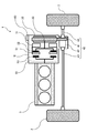
- FIG. 1 shows a configuration example of an electric vehicle 1 according to the embodiment.
- the electric vehicle 1 includes drive wheels 2, an internal combustion engine 3, and a vehicle drive device 10.
- the vehicle drive device 10 is mechanically connected to the internal combustion engine 3 and configured to drive the drive wheels 2.
- the electric vehicle 1 constitutes a so-called range extender.
- the vehicle drive device 10 includes a shaft 20, a first motor 31, a second motor 32, a power transmission mechanism 40, a power switching mechanism 50, and a control unit 60.
- the internal combustion engine 3 is configured to convert heat energy into rotational energy. Specifically, when fuel is combusted in a cylinder (not shown) of the internal combustion engine 3, a piston (not shown) of the internal combustion engine 3 operates to rotate the drive shaft of the internal combustion engine 3.
- the power of the internal combustion engine 3 is not set so that the drive wheels 2 can be driven alone, but is set so that the first motor 31 can generate power alone. In other words, the internal combustion engine 3 cannot generate power that can drive the drive wheels 2 alone, but can generate power that can generate the first motor 31 independently. ing. Therefore, the internal combustion engine 3 can be made smaller than the case where the internal combustion engine 3 is configured to be able to drive the drive wheels 2 independently.
- the first motor 31 is configured to convert electrical energy into rotational energy.
- the first motor 31 also has a function of converting rotational energy into electric energy (function of a generator). That is, the first motor 31 is configured to be able to be set in a state (drive state) in which electrical energy is converted into rotational energy and a state (in power generation state) in which rotational energy is converted into electrical energy.
- the rotor (not shown) of the first motor 31 rotates and rotational force is applied to the rotor of the first motor 31. Is applied, electric power is generated in the stator of the first motor 31.
- the first motor 31 is a low-speed motor configured to be able to generate power corresponding to the medium-low speed and low-load traveling of the electric vehicle 1.
- the low-speed motor (first motor 31) is configured to have a relatively low output, and the power required for the electric vehicle 1 to run at a medium to low speed and low load (or slightly higher than the required power). (Small power) can be generated.
- the low speed motor (first motor 31) is configured to have a relatively high efficiency in a low output region corresponding to medium to low speed and low load traveling of the electric vehicle 1. The medium / low speed low load driving and the low output region will be described in detail later.
- the first motor 31 is a permanent magnet motor.
- the first motor 31 is formed in a ring shape through which the shaft 20 passes in the center.
- the first motor 31 is not limited to this shape, and may be formed in a cylindrical shape or a disk shape.
- the second motor 32 is configured to convert electrical energy into rotational energy.
- the second motor 32 also has a function of converting rotational energy into electric energy (function of a generator). That is, the second motor 32 is configured to be settable in a state (drive state) in which electric energy is converted into rotational energy and a state (in power generation state) in which rotational energy is converted into electric energy.
- the rotor (not shown) of the second motor 32 rotates, and rotational force is applied to the rotor of the second motor 32. Is applied, power is generated in the stator of the second motor 32.
- the second motor 32 is configured to be connected to the shaft 20.
- the second motor 32 is configured to transmit power to a gear 41 (gear 41 connected to the shaft 20) described later.
- gear 41 gear 41 connected to the shaft 20
- the rotational force of the second motor 32 is transmitted to the shaft 20 via the gear 41 (a part of the power transmission mechanism 40).
- the shaft 20 rotates, the rotational force of the shaft 20 is transmitted to the second motor 32 via the gear 41 (a part of the power transmission mechanism 40).
- the second motor 32 is a high-speed motor configured to be able to generate power corresponding to high-speed traveling of the electric vehicle 1.
- the high-speed motor (second motor 32) is configured to have a relatively high output, and is configured to generate power necessary for the electric vehicle 1 to travel at high speed.
- the high-speed motor (second motor 32) is configured to have a relatively high efficiency in a high-output region corresponding to high-speed traveling of the electric vehicle 1. High-speed running and high-power areas will be described in detail later.
- the second motor 32 is configured by a magnetless motor that does not have a permanent magnet.
- magnetless motors include induction motors, switched reluctance motors, and synchronous reluctance motors.
- the second motor 32 is formed in a disk shape, and the gear 41 (a part of the power transmission mechanism 40) is arranged on the outer periphery thereof so that the power of the second motor 32 is transmitted to the gear 41. It is configured. Note that the second motor 32 is not limited to this shape, and may be formed in a cylindrical shape.
- the power transmission mechanism 40 is configured to transmit the power of the shaft 20 and the power of the second motor 32 to the drive wheels 2.
- the power transmission mechanism 40 includes a gear 41, a differential mechanism 42, and a drive shaft 43.
- the gear 41 is connected to the shaft 20.
- the differential mechanism 42 is mechanically connected to the drive shaft 43 and configured to transmit the power of the gear 41 to the drive shaft 43. Both ends of the drive shaft 43 are connected to the drive wheel 2.
- the power transmission mechanism 40 is configured to transmit power between the shaft 20 and the second motor 32 and the drive wheel 2.
- the gear 41 is arranged on the outer periphery of the second motor 32 so that the power of the second motor 32 is transmitted.
- the gear 41 is not limited to this configuration, and may be configured to mesh with a gear connected to the drive shaft of the second motor 32 formed in a cylindrical shape. Even in such a configuration, the second motor 32 can be interlocked with the shaft 20, and the power transmission mechanism 40 can transmit the power of the shaft 20 and the power of the second motor 32 to the drive wheels 2.
- the power switching mechanism 50 is connected to the first motor 31, the shaft 20, and the internal combustion engine 3, and is configured to be switchable between a first state, a second state, and a third state.
- the first state the state shown in FIG. 1
- the power transmission mechanism 40 allows power transmission between the first motor 31 and the shaft 20, while between the first motor 31 and the internal combustion engine 3. Prohibit power transmission.
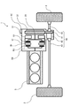
- the second state the state shown in FIG. 2
- the power transmission mechanism 40 prohibits power transmission between the first motor 31 and the shaft 20, and power between the first motor 31 and the internal combustion engine 3. Prohibit transmission.
- the power switching mechanism 50 allows power transmission between the first motor 31 and the internal combustion engine 3, while between the first motor 31 and the shaft 20. Prohibit power transmission.
- the power switching mechanism 50 includes a first clutch member 51, a second clutch member 52, and a third clutch member 53.
- the first clutch member 51 is connected to the first motor 31, the second clutch member 52 is connected to the shaft 20, and the third clutch member 53 is connected to the drive shaft of the internal combustion engine 3.
- the first clutch member 51 engages with the second clutch member 52 while being disconnected from the third clutch member 53.
- the first clutch member 51 is disconnected from both the second clutch member 52 and the third clutch member 53.
- the control unit 60 is configured to control the first motor 31, the second motor 32, the internal combustion engine 3, and the power switching mechanism 50.
- the control unit 60 includes a battery 61, a plug 62, a charger 63, a first inverter 71, a second inverter 72, and a controller 73.
- the battery 61 is configured to store electric power.
- the battery 61, the first inverter 71, and the second inverter 72 are electrically connected to each other.
- the plug 62 is configured to be connectable to an external power source (not shown).
- the charger 63 is electrically connected to the battery 61 and the plug 62, and is configured to store the power supplied from the external power source via the plug 62 in the battery 61 in response to control by the controller 73. .
- the first inverter 71 is electrically connected to the first motor 31.
- the first inverter 71 converts the power supplied to the first inverter 71 (for example, the power of the battery 61) into a desired first output power by a switching operation, and supplies the first output power to the first motor 31.
- the first inverter 71 is a low-speed motor inverter configured to supply first output power suitable for the first motor 31 that is a low-speed motor.
- the first inverter 71 (low-speed motor inverter) is configured to have a relatively low output, and the first motor 31 (low-speed motor) in the low-output region corresponding to the medium-low speed low-load traveling of the electric vehicle 1.
- the first output power is supplied so as to drive.
- the second inverter 72 is electrically connected to the second motor 32. Then, the second inverter 72 converts the power supplied to the second inverter 72 (for example, the power of the battery 61 or the power of the first motor 31) into a desired second output power by a switching operation, and converts the second output power. It is configured to supply to the second motor 32.
- the second inverter 72 is a high-speed motor inverter configured to supply second output power suitable for the second motor 32 that is a high-speed motor.
- the second inverter 72 (high-speed motor inverter) is configured to have a relatively high output, and the second motor 32 (high-speed motor) is driven in a high-output region corresponding to high-speed traveling of the electric vehicle 1.
- the second output power is supplied as follows.
- the controller 73 Based on the detection values of various sensors provided in each part of the electric vehicle 1, the controller 73 (specifically, the internal combustion engine 3, the charger 63, the first inverter 71, and the second inverter 72). ) Is configured to control.
- the controller 73 is configured by an ECU (Electronic Control Unit), a calculation processing unit such as a CPU (Central Processing Unit), and a memory (storage unit) that stores a program and information for operating the calculation processing unit. ).
- the various sensors include, for example, a rotational speed sensor configured to detect the rotational speed of each part such as the drive wheel 2, the first motor 31, the second motor 32, and the internal combustion engine 3, the first motor 31, and the second motor. 32, a current sensor configured to detect the current value of each part, a power sensor configured to detect the remaining amount of power stored in the battery 61, and the like (all not shown).
- control unit 60 performs the following operations in each of medium / low speed / low load travel, medium / low speed / high load travel, high speed travel, emergency travel, and regenerative travel during deceleration.
- the rotational speed of the driving wheel 2 is equal to or lower than a predetermined rotational speed threshold (for example, the rotational speed corresponding to 40 km / h), and the load of the driving wheel 2 is predetermined.
- a traveling state (so-called urban traveling) that is equal to or less than (for example, a load value corresponding to the maximum driving force that can be generated in the first motor 31).
- the medium / low speed / high load traveling is a traveling state in which the rotational speed of the driving wheel 2 is equal to or lower than the rotational speed threshold and the load of the driving wheel 2 exceeds the load threshold.
- High speed traveling is a traveling state in which the rotational speed of the drive wheel 2 exceeds the rotational speed threshold.
- the emergency travel is a state in which the electric vehicle 1 is traveled when the remaining amount of electric power stored in the battery 61 falls below a predetermined remaining amount threshold (for example, 20% of the maximum storage capacity). In regenerative travel during deceleration, the electric vehicle 1 is decelerated and the motor (at least one of the first motor 31 and the second motor 32) is generated using the rotational force of the drive wheels 2, and the electric power generated by the power generation is stored in the battery. This is the running state accumulated in 61.
- the control unit 60 When the rotational speed of the drive wheel 2 is equal to or lower than the rotational speed threshold value and the load of the drive wheel 2 is equal to or lower than the load threshold value (that is, in the case of medium / low speed / low load traveling), the control unit 60 The state (the state shown in FIG. 1) is set, the first motor 31 is set to the driving state, and the second motor 32 and the internal combustion engine 3 are set to the stopped state.
- the controller 73 sets the first motor 31 to the driving state by controlling the first inverter 71 so that power is supplied from the battery 61 to the first motor 31 via the first inverter 71. To do. Further, the controller 73 sets the second motor 32 in a stopped state by controlling the second inverter 72 so that power is not supplied from the battery 61 to the second motor 32 via the second inverter 72. To do.
- the power switching mechanism 50 is set to the first state.
- the first motor 31 is set in the driving state, and the second motor 32 and the internal combustion engine 3 are set in the stopped state.
- the power (rotational force) of the first motor 31 is transmitted to the drive wheels 2 through the power switching mechanism 50, the shaft 20, and the power transmission mechanism 40 in order, and the drive wheels 2 are driven by the power of the first motor 31. Is driven to rotate.
- the driving wheel 2 can be driven by using the power of the first motor 31 in the medium / low speed / low load traveling.
- the control unit 60 sets the power switching mechanism 50 in the first state when the rotation speed of the drive wheel 2 is equal to or less than the rotation speed threshold value and the load of the drive wheel 2 exceeds the load threshold value (that is, when traveling at a medium to low speed and high load). (The state shown in FIG. 1), the first motor 31 and the second motor 32 are set to the driving state, and the internal combustion engine 3 is set to the stopped state.
- the controller 73 includes the first inverter 71 and the second inverter so that electric power is supplied from the battery 61 to the first motor 31 and the second motor 32 via the first inverter 71 and the second inverter 72. 72 is controlled. Thereby, the 1st motor 31 and the 2nd motor 32 are set to a drive state.
- the power switching mechanism 50 is set to the first state.
- the first motor 31 and the second motor 32 are set to the driving state, and the internal combustion engine 3 is set to the stopped state.
- the power (rotational force) of the first motor 31 is transmitted to the drive wheels 2 through the power switching mechanism 50, the shaft 20, and the power transmission mechanism 40 in order, and the drive wheels 2 are driven by the power of the first motor 31.
- the power (rotational force) of the second motor 32 is transmitted to the drive wheels 2 via the power transmission mechanism 40, and the drive of the drive wheels 2 is assisted by the power of the second motor 32.
- the driving wheel 2 can be driven using the power of the first motor 31 and the driving of the driving wheel 2 can be assisted using the power of the second motor 32. it can.
- the controller 60 sets the power switching mechanism 50 to the second state (the state shown in FIG. 2) when the rotational speed of the drive wheel 2 exceeds the rotational speed threshold (that is, when traveling at high speed), and the second motor 32 is set to the drive state, and the first motor 31 and the internal combustion engine 3 are set to the stop state.
- the controller 73 sets the second motor 32 in a driving state by controlling the second inverter 72 so that power is supplied from the battery 61 to the second motor 32 via the second inverter 72. To do.
- the controller 73 sets the first motor 31 to a stopped state by controlling the first inverter 71 so that power is not supplied from the battery 61 to the first motor 31 via the first inverter 71. To do.
- the power switching mechanism 50 is set to the second state, the second motor 32 is set to the driving state, and the first The motor 31 and the internal combustion engine 3 are set to a stopped state.
- the power (rotational force) of the second motor 32 is transmitted to the drive wheels 2 via the power transmission mechanism 40, and the drive wheels 2 are driven to rotate by the power of the second motor 32.
- the drive wheels 2 can be driven using the power of the second motor 32.
- the control unit 60 sets the power switching mechanism 50 to the third state (the state shown in FIG. 3) when the remaining amount of electric power stored in the battery 61 is lower than the remaining amount threshold value (that is, in the case of emergency running). Then, the internal combustion engine 3 is set to the drive state, and the second motor 32 is set to the drive state using the electric power generated in the first motor 31.
- the controller 73 first controls the first inverter 31 by controlling the first inverter 71 such that the electric power stored in the battery 61 is supplied to the first motor 31 via the first inverter 71. Is set to the driving state. Next, the controller 73 starts the internal combustion engine 3 with the power of the first motor 31 and sets the internal combustion engine 3 to a driving state. When the internal combustion engine 3 is set to the driving state, the controller 73 controls the first inverter 71 so that the power supply from the battery 61 to the first motor 31 is stopped. As a result, the first motor 31 is driven by the power of the internal combustion engine 3 to generate electricity.
- the controller 73 supplies the first inverter 71 and the second inverter so that the electric power generated in the first motor 31 is supplied to the second motor 32 via the first inverter 71 and the second inverter 72 in order.
- the second motor 32 is set to a driving state by controlling 72.
- the control unit 60 is configured to accumulate in the battery 61 surplus power that is not used for driving the second motor 32 out of the power generated by the first motor 31.
- the controller 73 supplies a part of the electric power generated in the first motor 31 to the second motor 32 via the first inverter 71 and the second inverter 72 in order, while the first motor 31
- the first inverter 71 and the second inverter 72 are controlled such that the remainder of the power generated at 31 is supplied to the battery 61 via the first inverter 71.
- surplus power is stored in the battery 61 while the second motor 32 is set to the driving state.
- the power switching mechanism 50 is set to the third state, and the internal combustion engine 3 Is set to the driving state.
- the power (rotational force) of the internal combustion engine 3 is transmitted to the first motor 31 via the power switching mechanism 50, and the first motor 31 is driven by the power of the internal combustion engine 3 to generate power.
- the second motor 32 is set in a driving state using the electric power generated in the first motor 31.
- the electric power of the first motor 31 is supplied to the second motor 32 via the first inverter 71 and the second inverter 72, and the second motor 32 is driven and rotated by the electric power of the first motor 31.
- the power (rotational force) of the second motor 32 is transmitted to the drive wheels 2 via the power transmission mechanism 40, and the drive wheels 2 are driven and rotated by the power of the second motor 32.
- surplus power that is not used for driving the second motor 32 out of the power of the first motor 31 is supplied to the battery 61 and stored therein.
- the second motor 32 can be driven using the electric power generated in the first motor 31, and the driving wheels 2 can be driven using the power of the second motor 32. . Further, surplus power that is not used to drive the second motor 32 among the power generated in the first motor 31 can be stored in the battery 61.
- the control unit 60 sets the power switching mechanism 50 to the first state (the state shown in FIG. 1) when the electric vehicle 1 decelerates (that is, in the case of regenerative travel during deceleration), and the first motor 31 and the second motor At least one of the motors 32 is set in a power generation state, the internal combustion engine 3 is set in a stopped state, and regenerative power generated in at least one of the first motor 31 and the second motor 32 is stored in the battery 61. ing.
- the controller 73 determines whether or not the electric vehicle 1 is decelerating based on a change in the rotational speed of the drive wheels 2, and when determining that the electric vehicle 1 is decelerating, the power switching mechanism 50. Is set to the first state. Then, the controller 73 obtains the regenerative brake amount according to the deceleration of the electric vehicle 1 (specifically, the depression amount of the brake pedal (not shown) of the electric vehicle 1). The controller 73 controls at least one of the first inverter 71 and the second inverter 72 so that the regenerative braking amount is obtained, and generates power at least one of the first motor 31 and the second motor 32. The controller 73 is configured to determine which of the first motor 31 and the second motor 32 is to generate electric power according to the magnitude of the rotational speed of the drive wheel 2 and the magnitude of the regenerative brake amount. May be.
- the power switching mechanism 50 is set to the first state, and at least one of the first motor 31 and the second motor 32 is set to the power generation state. Then, the internal combustion engine 3 is set to a stopped state. Thereby, the rotational force of the drive wheel 2 is transmitted to the shaft 20 and the second motor 32 via the power transmission mechanism 40 and the second motor 32 rotates, and the power of the shaft 20 passes via the power switching mechanism 50.
- the first motor 31 is rotated by being transmitted to the first motor 31.
- the motor set in the power generation state among the first motor 31 and the second motor 32 generates power, and the electric power (regenerated power) generated by the power generation is accumulated in the battery 61.
- the control unit 60 sets the power switching mechanism 50 to the second state (the state shown in FIG. 2) when the electric vehicle 1 decelerates relatively slowly (that is, in the case of non-accelerated traveling), and the first motor 31, the second motor 32, and the internal combustion engine 3 are set to a stopped state. Further, the control unit 60 sets the power switching mechanism 50 in the first state (shown in FIG. 1) when the electric vehicle 1 decelerates relatively abruptly (for example, when the brake pedal of the electric vehicle 1 is depressed). State), at least one of the first motor 31 and the second motor 32 is set to the power generation state, and the internal combustion engine 3 is set to the stop state.
- Non-accelerated traveling is a traveling state in which the electric vehicle 1 is slowly decelerated. Specifically, both the accelerator pedal and the brake pedal (both not shown) of the electric vehicle 1 are depressed. This is a traveling state in which the deceleration of the electric vehicle 1 is below a predetermined deceleration threshold.
- the control unit 60 brings the power switching mechanism 50 into the first state (the state shown in FIG. 1) or the second state (the state shown in FIG. 2).
- the first motor 31, the second motor 32, and the internal combustion engine 3 are set to a stopped state.
- the control unit 60 sets the power switching mechanism 50 to the first state (the state illustrated in FIG. 1), and the first motor 31 and the second motor 32. Is set to the power generation state, and the internal combustion engine 3 is set to the stop state. In this way, the regenerative power generated in at least one of the first motor 31 and the second motor 32 may be configured to be stored in the battery 61.
- the control unit 60 releases the accelerator pedal of the electric vehicle 1 during medium / low speed driving (medium / low speed / low load driving or medium / low speed / high load driving) and the electric vehicle 1 is not accelerated.
- medium / low speed driving medium / low speed / low load driving or medium / low speed / high load driving
- the electric vehicle 1 is not accelerated.
- Predetermined standby from the time when the vehicle is traveling that is, a traveling state in which neither the accelerator pedal nor the brake pedal of the electric vehicle 1 is depressed and the deceleration of the electric vehicle 1 is below the deceleration threshold.
- the first non-accelerated running operation is performed until time (for example, several seconds) elapses.
- the second non-accelerated traveling operation is performed after the standby time has elapsed from the time when the electric vehicle 1 has become non-accelerated traveling during the medium-low speed traveling of the electric vehicle 1, and the electric vehicle 1 is in non-accelerated traveling.
- the brake pedal of the electric vehicle 1 When the brake pedal of the electric vehicle 1 is depressed, the regenerative travel operation during deceleration may be performed.
- the power switching mechanism 50 In the first non-accelerated running operation, the power switching mechanism 50 is set to the first state (the state shown in FIG. 1), and the first motor 31, the second motor 32, and the internal combustion engine 3 are set to the stopped state. It is an operation.
- the second non-accelerated running operation is an operation of setting the power switching mechanism 50 to the second state (the state shown in FIG.
- the power switching mechanism 50 is set to the first state, at least one of the first motor 31 and the second motor 32 is set to the power generation state, the internal combustion engine 3 is set to the stop state, and the first This is an operation for accumulating regenerative power generated in at least one of the motor 31 and the second motor 32 in the battery 61.
- the second non-accelerated running operation (the power switching mechanism 50 is set to the second state, and the first motor 31, the second motor 32, and the internal combustion engine 3 are stopped). Set operation). As a result, power generation in the first motor 31 and the second motor 32 can be suppressed and the inertial travel distance of the electric vehicle 1 can be extended.
- the electric pedal 1 When the electric pedal 1 is switched from the accelerator pedal to the brake pedal during medium / low speed driving (medium / low speed / low load driving or medium / low speed / high load driving), the electric vehicle 1 is driven at medium / low speed and non-accelerated driving for a short period of time. And regenerative running during deceleration. Therefore, when the control unit 60 is configured to perform the second non-accelerated traveling operation immediately after the electric vehicle 1 becomes non-accelerated traveling during the medium / low-speed traveling of the electric vehicle 1, the medium / low-speed traveling of the electric vehicle 1 is performed.
- the accelerator pedal is switched to the brake pedal, the power switching mechanism 50 is switched from the first state to the second state in a short period and then switched to the first state again. Thus, if the power switching mechanism 50 is frequently switched in a short period of time, there is a risk that a shock will occur in the electric vehicle 1.
- a standby time (specifically, a time longer than the time required for the switching operation from the accelerator pedal to the brake pedal) from the time when the electric vehicle 1 becomes non-accelerated during the low-speed driving of the electric vehicle 1 is obtained.
- the first non-accelerated running operation is performed until the time elapses
- the second non-accelerated running operation is performed after the standby time has elapsed from the time when the electric vehicle 1 has entered non-accelerated running.
- the state of the power switching mechanism 50 is frequently switched (specifically, the switching of the power switching mechanism 50 due to the switching operation from the accelerator pedal to the brake pedal while the electric vehicle 1 is traveling at a medium to low speed). (The state is frequently switched).
- the power of the first motor 31 and the power of the second motor 32 are set by setting the power switching mechanism 50 to the first state (the state shown in FIG. 1).
- the drive wheel 2 can be driven using Further, by setting the power switching mechanism 50 to the second state (the state shown in FIG. 2), the driving wheels 2 can be driven using the power of the second motor 32.
- the power switching mechanism 50 to the third state (the state shown in FIG. 3)
- the first motor 31 can be generated using the power of the internal combustion engine 3.
- the vehicle drive device 10 can be made smaller than the case of providing (that is, providing three rotating electric machines). Thereby, since the occupation space of the vehicle drive device 10 inside the electric vehicle 1 can be reduced, the internal space of the electric vehicle 1 can be used effectively.
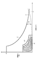
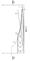
- the running resistance curve L ⁇ b> 1 corresponds to the running resistance of the electric vehicle 1.
- the running resistance is determined based on the rolling resistance, air resistance, gradient resistance, and acceleration resistance of the electric vehicle 1.
- the running resistance curve L1 corresponds to the running resistance when the gradient is zero and the acceleration resistance is zero (that is, when running on a flat road surface at a constant speed).
- the required power performance curve L2 corresponds to the required power performance determined based on the running resistance L1 (the driving force required for the vehicle drive device 10 for running the electric vehicle 1).
- the maximum driving force P1 corresponds to a driving force (power for driving the driving wheels 2) required when starting from the maximum gradient with the maximum loading amount.
- Maximum speed V1 corresponds to the speed of electric vehicle 1 at the intersection of travel resistance curve L1 and required power performance curve L2.
- the marginal driving force P0 corresponds to the difference between the travel resistance and the required power performance (specifically, the difference between the travel resistance value of the travel resistance curve L1 corresponding to the common speed value and the required power performance value of the required power performance L2). This is a factor that determines the acceleration performance of the electric vehicle 1. For example, in an electric vehicle 1 that has a relatively sharp acceleration and a relatively high maximum speed, such as a sports car, the required power performance tends to be relatively high.
- the first power characteristic curve L31 corresponds to the power characteristic of the first motor 31 (that is, the driving force that can be generated in the first motor 31).
- the driving force and speed in the first power characteristic curve L31 are based on the gear ratio in the vehicle drive device 10, the diameter of the driving wheel 2 (tire diameter), and the like, and the torque rotation speed characteristic of the first motor 31 (see FIG. 6). Is obtained by converting the torque and the rotational speed at. Further, the percentages (95%, 85%, 75%, 65%) in the figure indicate the overall efficiency of the first motor 31.
- the overall efficiency of the first motor 31 includes the copper loss and iron loss of the first motor 31 and the loss of the first inverter 71 connected to the first motor 31.
- the rotational speed of the driving wheel 2 is relatively low and the load of the driving wheel 2 is relatively low. Therefore, the operating points of the electric vehicle 1 tend to concentrate in a low speed and low load region (a region where the speed is relatively low and the load is relatively low).
- the first motor 31 (low speed motor) has a low output range (the number of rotations (speed) is equal to or less than a predetermined number of rotations threshold and corresponds to a predetermined load) corresponding to medium to low speed low-load traveling of the electric vehicle 1.
- the output region is less than or equal to the load threshold) so that the efficiency is relatively high. Therefore, the driving wheels 2 can be driven efficiently by driving the driving wheels 2 using the power of the first motor 31 in the medium to low speed and low load traveling of the electric vehicle 1.
- the first motor 31 is a permanent magnet motor.
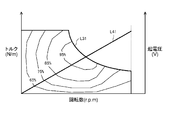
- the driving force and speed are converted into torque and rotational speed, respectively. That is, in FIG. 6, the first power characteristic curve L31 corresponds to the torque rotation speed characteristic of the first motor 31.
- the electromotive force characteristic curve L41 corresponds to the electromotive voltage of the first motor 31 resulting from the rotation of the first motor 31.
- the permanent magnet motor when the rotor of the permanent magnet motor (rotor having a permanent magnet) rotates, eddy current is generated in the stator of the permanent magnet motor and iron loss occurs. And as the rotational speed of the permanent magnet motor increases, eddy currents generated in the permanent magnet motor tend to increase.
- the first motor 31 that is a low-speed motor is configured by a permanent magnet motor
- the second motor 32 that is a high-speed motor is a magnetless motor (induction motor, switched reluctance motor, synchronous reluctance). Motor). Therefore, even when the second motor 32 rotates with the rotation of the shaft 20 during the medium / low speed / low load traveling, no electromotive voltage or eddy current is generated in the second motor 32 constituted by the magnetless motor. Therefore, it is possible to avoid an increase in electromotive voltage and eddy current loss in the second motor 32.
- the power characteristic of the 2nd motor 32 (high-speed motor) comprised with the magnet-less motor is demonstrated.
- the second power characteristic curve L32 corresponds to the power characteristic of the second motor 32 (that is, the driving force that can be generated in the second motor 32).
- no electromotive voltage is generated in the second motor 32 constituted by a magnetless motor. Therefore, the second motor 32 (high-speed motor) has relatively high efficiency in a high-output region (output region where the rotational speed (speed) exceeds a predetermined rotational speed threshold) corresponding to high-speed traveling of the electric vehicle 1. It is comprised so that it may become. Therefore, when the electric vehicle 1 is traveling at high speed, the driving force of the driving wheel 2 can be efficiently performed by driving the driving wheel 2 using the power of the second motor 32 configured by a magnetless motor.
- the second power characteristic curve L32 corresponds to the power characteristic of the second motor 32 (that is, the driving force that can be generated in the second motor 32).
- the total power characteristic curve L33 is a curve obtained by combining the first power characteristic curve L31 and the second power characteristic curve L32 (that is, the total amount of driving force that can be generated in the first motor 31 and the second motor 32). ).
- the second motor 32 (high-speed motor) is a high-output region corresponding to high-speed travel of the electric vehicle 1 (an output region where the rotational speed (speed) exceeds a predetermined rotational speed threshold). It is comprised so that it may become comparatively high efficiency. Therefore, when the electric vehicle 1 is traveling at high speed, the driving wheels 2 can be driven efficiently by driving the driving wheels 2 using the power of the second motor 32.
- the second power characteristic curve L32 corresponds to the power characteristic of the second motor 32 (that is, the driving force that can be generated in the second motor 32).
- the second electromotive voltage characteristic curve L42 corresponds to the electromotive voltage of the second motor 32 caused by the rotation of the second motor 32.
- the power characteristic of the second motor 32 is set so that the slope of the second electromotive voltage characteristic curve L42 becomes gentle. Thereby, the increase in the electromotive force of the 2nd motor accompanying the increase in the rotation speed of the 2nd motor 32 can be suppressed, and the frequency by which field-weakening control is performed can be reduced.
- the second motor 32 (high-speed motor) is relatively high in a high-output region (an output region in which the rotational speed (speed) exceeds a predetermined rotational speed threshold) corresponding to high-speed traveling of the electric vehicle 1. It is configured to be efficient. Therefore, when the electric vehicle 1 is traveling at high speed, the driving wheels 2 can be driven efficiently by driving the driving wheels 2 using the power of the second motor 32.
- FIG. 10 shows an example of driving the drive wheels 2 using one motor.
- a power characteristic curve L90 corresponds to the power characteristic of the comparative example of the motor (that is, the driving force that can be generated in one motor).
- the operating point of the electric vehicle in the medium / low speed / low load traveling is the low efficiency region of the motor (the region where the motor efficiency is relatively low ).
- field weakening control is performed in the high rotation region R2 in order to reduce the electromotive voltage of the motor.
- the field of the permanent magnet of the permanent magnet motor is weakened and the motor can be rotated at high speed.
- the efficiency of the motor is lowered by weakening the field of the permanent magnet in the high rotation region R2.
- the drive motor 2 is driven over a wide range from low speed to high speed by using the first motor 31 that is a low-speed motor and the second motor 32 that is a high-speed motor. It can be done efficiently.
- this disclosure is applicable to a vehicle drive device.
Landscapes
- Engineering & Computer Science (AREA)
- Transportation (AREA)
- Mechanical Engineering (AREA)
- Chemical & Material Sciences (AREA)
- Combustion & Propulsion (AREA)
- Power Engineering (AREA)
- Automation & Control Theory (AREA)
- Life Sciences & Earth Sciences (AREA)
- Sustainable Development (AREA)
- Sustainable Energy (AREA)
- Electric Propulsion And Braking For Vehicles (AREA)
- Hybrid Electric Vehicles (AREA)
Abstract
Dans la présente invention, un second moteur est accouplé à un arbre. Un mécanisme de transmission de puissance transmet une puissance à partir de l'arbre et une puissance à partir du second moteur à une roue motrice. Un mécanisme de commutation de puissance est raccordé à un premier moteur, à l'arbre et à un moteur à combustion interne. Le mécanisme de commutation de puissance peut commuter entre : un premier état dans lequel une transmission de puissance entre le premier moteur et l'arbre est autorisée ; un deuxième état dans lequel une transmission de puissance entre le premier moteur et l'arbre est interdite et une transmission de puissance entre le premier moteur et le moteur à combustion interne est interdite ; et un troisième état dans lequel une transmission de puissance entre le premier moteur et le moteur à combustion interne est autorisée.
Priority Applications (2)
| Application Number | Priority Date | Filing Date | Title |
|---|---|---|---|
| JP2018508523A JP6646846B2 (ja) | 2016-03-30 | 2017-02-13 | 車両駆動装置および電気車両 |
| US16/087,009 US20190092316A1 (en) | 2016-03-30 | 2017-02-13 | Vehicle drive device and electric vehicle |
Applications Claiming Priority (2)
| Application Number | Priority Date | Filing Date | Title |
|---|---|---|---|
| JP2016068860 | 2016-03-30 | ||
| JP2016-068860 | 2016-03-30 |
Publications (1)
| Publication Number | Publication Date |
|---|---|
| WO2017169180A1 true WO2017169180A1 (fr) | 2017-10-05 |
Family
ID=59964022
Family Applications (1)
| Application Number | Title | Priority Date | Filing Date |
|---|---|---|---|
| PCT/JP2017/005039 Ceased WO2017169180A1 (fr) | 2016-03-30 | 2017-02-13 | Dispositif d'entraînement de véhicule et véhicule électrique |
Country Status (3)
| Country | Link |
|---|---|
| US (1) | US20190092316A1 (fr) |
| JP (1) | JP6646846B2 (fr) |
| WO (1) | WO2017169180A1 (fr) |
Cited By (1)
| Publication number | Priority date | Publication date | Assignee | Title |
|---|---|---|---|---|
| CN111572367A (zh) * | 2020-05-28 | 2020-08-25 | 安徽江淮汽车集团股份有限公司 | 内燃机式集成发电机系统及汽车 |
Families Citing this family (5)
| Publication number | Priority date | Publication date | Assignee | Title |
|---|---|---|---|---|
| JP2019103250A (ja) * | 2017-12-01 | 2019-06-24 | トヨタ自動車株式会社 | 電動車両 |
| DE102018208425B4 (de) * | 2018-05-28 | 2026-01-29 | Bayerische Motoren Werke Aktiengesellschaft | Antriebsstrang für ein Kraftfahrzeug, insbesondere für einen Kraftwagen, sowie Verfahren zum Betreiben eines solchen Antriebsstrangs |
| CN114286768B (zh) * | 2020-07-31 | 2024-06-21 | 日产自动车株式会社 | 串联混合动力车辆的控制方法以及串联混合动力车辆 |
| EP4092888A1 (fr) * | 2021-05-17 | 2022-11-23 | Ningbo Geely Automobile Research & Development Co. Ltd. | Unité d'entraînement électrique pour un véhicule |
| US20250313078A1 (en) * | 2024-04-08 | 2025-10-09 | Ford Global Technologies, Llc | Power unit for front beam axle |
Citations (2)
| Publication number | Priority date | Publication date | Assignee | Title |
|---|---|---|---|---|
| JP2004352042A (ja) * | 2003-05-28 | 2004-12-16 | Hino Motors Ltd | ハイブリッド自動車 |
| JP2012030775A (ja) * | 2010-07-08 | 2012-02-16 | Denso Corp | 車両用動力伝達装置 |
-
2017
- 2017-02-13 WO PCT/JP2017/005039 patent/WO2017169180A1/fr not_active Ceased
- 2017-02-13 US US16/087,009 patent/US20190092316A1/en not_active Abandoned
- 2017-02-13 JP JP2018508523A patent/JP6646846B2/ja active Active
Patent Citations (2)
| Publication number | Priority date | Publication date | Assignee | Title |
|---|---|---|---|---|
| JP2004352042A (ja) * | 2003-05-28 | 2004-12-16 | Hino Motors Ltd | ハイブリッド自動車 |
| JP2012030775A (ja) * | 2010-07-08 | 2012-02-16 | Denso Corp | 車両用動力伝達装置 |
Cited By (1)
| Publication number | Priority date | Publication date | Assignee | Title |
|---|---|---|---|---|
| CN111572367A (zh) * | 2020-05-28 | 2020-08-25 | 安徽江淮汽车集团股份有限公司 | 内燃机式集成发电机系统及汽车 |
Also Published As
| Publication number | Publication date |
|---|---|
| JP6646846B2 (ja) | 2020-02-14 |
| JPWO2017169180A1 (ja) | 2019-01-31 |
| US20190092316A1 (en) | 2019-03-28 |
Similar Documents
| Publication | Publication Date | Title |
|---|---|---|
| JP6646846B2 (ja) | 車両駆動装置および電気車両 | |
| JP6363585B2 (ja) | 車両 | |
| JP2009142036A (ja) | 電動車両 | |
| JP6096411B2 (ja) | ハイブリッド車両の発電制御装置 | |
| JP2013544693A (ja) | ハイブリッド駆動装置 | |
| JP2013150477A (ja) | 車両の駆動装置 | |
| JP6626519B2 (ja) | 車両用制御装置 | |
| JP7367373B2 (ja) | モータ制御システム | |
| JP2009227221A (ja) | ハイブリッド電気自動車 | |
| WO2019190389A1 (fr) | Procédé et système de propulsion de véhicule électrique | |
| JP2013184663A (ja) | 車両用制御装置 | |
| JPH07250403A (ja) | 電気車の制御装置 | |
| JP5515334B2 (ja) | ハイブリッド車両の制御装置 | |
| JP2010213429A (ja) | 回転電機 | |
| JP5267340B2 (ja) | インホイールモータの動力伝達機構 | |
| JP6436433B2 (ja) | 車両用電源装置および車両用電源装置の制御方法 | |
| JP7386355B2 (ja) | ハイブリッド車両の制御方法、及び、ハイブリッド車両 | |
| JP2012121466A (ja) | ハイブリッド電気自動車の制御装置 | |
| JP2017149208A (ja) | 自動運転装置 | |
| JP4765877B2 (ja) | 車両のモータトラクション制御装置 | |
| JP7647538B2 (ja) | 車両の制御装置 | |
| US10427528B2 (en) | Vehicle | |
| CN223314826U (zh) | 一种驱动总成及车辆 | |
| JP5971352B2 (ja) | 車両用電動機の制御装置 | |
| JP5853800B2 (ja) | 車両用電動発電装置 |
Legal Events
| Date | Code | Title | Description |
|---|---|---|---|
| WWE | Wipo information: entry into national phase |
Ref document number: 2018508523 Country of ref document: JP |
|
| NENP | Non-entry into the national phase |
Ref country code: DE |
|
| 121 | Ep: the epo has been informed by wipo that ep was designated in this application |
Ref document number: 17773728 Country of ref document: EP Kind code of ref document: A1 |
|
| 122 | Ep: pct application non-entry in european phase |
Ref document number: 17773728 Country of ref document: EP Kind code of ref document: A1 |