WO2017169198A1 - Couvercle pour tube pour sciences de la vie, ensemble de tubes pour sciences de la vie et procédé de séparation de cellules - Google Patents
Couvercle pour tube pour sciences de la vie, ensemble de tubes pour sciences de la vie et procédé de séparation de cellules Download PDFInfo
- Publication number
- WO2017169198A1 WO2017169198A1 PCT/JP2017/005200 JP2017005200W WO2017169198A1 WO 2017169198 A1 WO2017169198 A1 WO 2017169198A1 JP 2017005200 W JP2017005200 W JP 2017005200W WO 2017169198 A1 WO2017169198 A1 WO 2017169198A1
- Authority
- WO
- WIPO (PCT)
- Prior art keywords
- tube
- life science
- lid
- cell
- cells
- Prior art date
- Legal status (The legal status is an assumption and is not a legal conclusion. Google has not performed a legal analysis and makes no representation as to the accuracy of the status listed.)
- Ceased
Links
Images





Classifications
-
- C—CHEMISTRY; METALLURGY
- C12—BIOCHEMISTRY; BEER; SPIRITS; WINE; VINEGAR; MICROBIOLOGY; ENZYMOLOGY; MUTATION OR GENETIC ENGINEERING
- C12M—APPARATUS FOR ENZYMOLOGY OR MICROBIOLOGY; APPARATUS FOR CULTURING MICROORGANISMS FOR PRODUCING BIOMASS, FOR GROWING CELLS OR FOR OBTAINING FERMENTATION OR METABOLIC PRODUCTS, i.e. BIOREACTORS OR FERMENTERS
- C12M1/00—Apparatus for enzymology or microbiology
-
- C—CHEMISTRY; METALLURGY
- C12—BIOCHEMISTRY; BEER; SPIRITS; WINE; VINEGAR; MICROBIOLOGY; ENZYMOLOGY; MUTATION OR GENETIC ENGINEERING
- C12M—APPARATUS FOR ENZYMOLOGY OR MICROBIOLOGY; APPARATUS FOR CULTURING MICROORGANISMS FOR PRODUCING BIOMASS, FOR GROWING CELLS OR FOR OBTAINING FERMENTATION OR METABOLIC PRODUCTS, i.e. BIOREACTORS OR FERMENTERS
- C12M1/00—Apparatus for enzymology or microbiology
- C12M1/24—Apparatus for enzymology or microbiology tube or bottle type
-
- C—CHEMISTRY; METALLURGY
- C12—BIOCHEMISTRY; BEER; SPIRITS; WINE; VINEGAR; MICROBIOLOGY; ENZYMOLOGY; MUTATION OR GENETIC ENGINEERING
- C12M—APPARATUS FOR ENZYMOLOGY OR MICROBIOLOGY; APPARATUS FOR CULTURING MICROORGANISMS FOR PRODUCING BIOMASS, FOR GROWING CELLS OR FOR OBTAINING FERMENTATION OR METABOLIC PRODUCTS, i.e. BIOREACTORS OR FERMENTERS
- C12M1/00—Apparatus for enzymology or microbiology
- C12M1/26—Inoculator or sampler
- C12M1/28—Inoculator or sampler being part of container
-
- C—CHEMISTRY; METALLURGY
- C12—BIOCHEMISTRY; BEER; SPIRITS; WINE; VINEGAR; MICROBIOLOGY; ENZYMOLOGY; MUTATION OR GENETIC ENGINEERING
- C12N—MICROORGANISMS OR ENZYMES; COMPOSITIONS THEREOF; PROPAGATING, PRESERVING, OR MAINTAINING MICROORGANISMS; MUTATION OR GENETIC ENGINEERING; CULTURE MEDIA
- C12N1/00—Microorganisms; Compositions thereof; Processes of propagating, maintaining or preserving microorganisms or compositions thereof; Processes of preparing or isolating a composition containing a microorganism; Culture media therefor
-
- C—CHEMISTRY; METALLURGY
- C12—BIOCHEMISTRY; BEER; SPIRITS; WINE; VINEGAR; MICROBIOLOGY; ENZYMOLOGY; MUTATION OR GENETIC ENGINEERING
- C12Q—MEASURING OR TESTING PROCESSES INVOLVING ENZYMES, NUCLEIC ACIDS OR MICROORGANISMS; COMPOSITIONS OR TEST PAPERS THEREFOR; PROCESSES OF PREPARING SUCH COMPOSITIONS; CONDITION-RESPONSIVE CONTROL IN MICROBIOLOGICAL OR ENZYMOLOGICAL PROCESSES
- C12Q1/00—Measuring or testing processes involving enzymes, nucleic acids or microorganisms; Compositions therefor; Processes of preparing such compositions
- C12Q1/68—Measuring or testing processes involving enzymes, nucleic acids or microorganisms; Compositions therefor; Processes of preparing such compositions involving nucleic acids
-
- G—PHYSICS
- G01—MEASURING; TESTING
- G01N—INVESTIGATING OR ANALYSING MATERIALS BY DETERMINING THEIR CHEMICAL OR PHYSICAL PROPERTIES
- G01N21/00—Investigating or analysing materials by the use of optical means, i.e. using sub-millimetre waves, infrared, visible or ultraviolet light
- G01N21/01—Arrangements or apparatus for facilitating the optical investigation
-
- G—PHYSICS
- G01—MEASURING; TESTING
- G01N—INVESTIGATING OR ANALYSING MATERIALS BY DETERMINING THEIR CHEMICAL OR PHYSICAL PROPERTIES
- G01N21/00—Investigating or analysing materials by the use of optical means, i.e. using sub-millimetre waves, infrared, visible or ultraviolet light
- G01N21/17—Systems in which incident light is modified in accordance with the properties of the material investigated
-
- G—PHYSICS
- G01—MEASURING; TESTING
- G01N—INVESTIGATING OR ANALYSING MATERIALS BY DETERMINING THEIR CHEMICAL OR PHYSICAL PROPERTIES
- G01N33/00—Investigating or analysing materials by specific methods not covered by groups G01N1/00 - G01N31/00
- G01N33/48—Biological material, e.g. blood, urine; Haemocytometers
Definitions
- the present invention relates to a life science tube lid, a life science tube set, and a cell selection method, and more particularly, to a life science tube lid, a life science tube set, and a life science tube suitable for cell image analysis.
- the present invention relates to a method for sorting cells using a lid.
- the target cells are separated by flow cytometry.
- flow cytometry fine cells are dispersed in a fluid, the fluid is finely flowed, individual cells are optically analyzed, and the obtained cells are judged and sorted based on the analysis results. Is.
- a plurality of cells are dropped together on a well slide, dropped into a minute well, photographed and analyzed, and target cells are identified. Thereafter, the specified target cell is sucked with a capillary and transferred to a PCR (polymerase chain reaction) plate or tube.
- PCR polymerase chain reaction
- Patent Document 1 describes a reaction container having a removable lid on a tube used for PCR.
- the present invention has been made in view of such circumstances, and is a life science tube that can efficiently perform subsequent analysis or preprocessing of analysis by performing image analysis using a lid.
- An object of the present invention is to provide a lid, a tube set for life science, and a cell sorting method.
- the present invention is a life science tube lid having a recess on the side of the life science tube, the bottom surface of the recess being flat, and a circular or quadrangular or more polygonal shape.
- a lid for a life science tube having an inclined surface whose side surface is widened from the bottom surface toward the opening.
- the lid of the tube for life science of the present invention has a recess on the surface side on which the tube for life science is mounted, and by flattening the bottom surface of this recess, An image of the specimen can be taken.
- By flattening the bottom surface of the concave portion of the lid it is possible to focus on the specimen in the concave portion, and a good image can be taken.
- the opening portion can be widened and the specimen can easily enter the concave portion. Further, by narrowing toward the bottom surface, the size of the bottom surface can be reduced, and the size of the bottom surface with respect to the specimen can be set within a predetermined range. Therefore, in the image analysis of the specimen, the entire bottom surface can be imaged by photographing with one visual field, and the imaging and the image analysis of the specimen can be performed efficiently.
- the side surface an inclined surface that expands toward the opening, it is possible to easily remove bubbles in the culture solution, and it is possible to prevent light from being refracted by the bubbles and to obtain a good image. An image can be taken.
- life science refers to handling of cells and biomolecules, and more specifically includes cell culture, detection, separation, purification, analysis and evaluation, and biomolecules. This refers to those used for the synthesis, detection, separation, purification, analysis and evaluation of compounds, and the “life science tube” refers to a container used for life science applications.
- the “life science tube side” is the surface on which the life science tube is mounted. When used with the life science tube, it forms a space between the lid of the life science tube and the tube. It means the surface side.
- the side surface preferably has two or more inclined surfaces having different angles with respect to the bottom surface.
- the degree of freedom in designing the side surface of the concave portion can be increased by making the side surface of the concave portion of the lid into two or more inclined surfaces having different angles with respect to the bottom surface. For example, by increasing the angle on the opening side of the recess, the specimen can be more easily entered into the recess. Further, by reducing the angle of the bottom surface side of the side surface, the bottom surface can be narrowed, and the bottom surface can be imaged with a single image even if the magnification during imaging is increased. By increasing the angle on the bottom side of the side surface, the sample introduced into the recess can be prevented from staying on the side surface, and can be dropped to the bottom surface.
- the size of the bottom surface is preferably 0.05 mm ⁇ or more and 1 mm ⁇ or less when approximated to a circumscribed circle.
- the entire bottom surface is captured by a single image by capturing with an objective lens having a magnification (5 to 63 times) used for capturing normal images. can do. Therefore, it is possible to efficiently perform imaging and image analysis of the specimen.
- the transmittance for light having a wavelength of 350 nm or more and 800 nm or less is preferably 60% or more.
- a good image can be taken by setting the transmittance of the material used for the lid of the life science tube to light having the above wavelength to 60% or more.
- it is preferably formed of acrylic resin, polypropylene, or polystyrene.
- the material used for the lid of the life science tube is limited.
- acrylic resin, polypropylene, or polystyrene By using acrylic resin, polypropylene, or polystyrene, the transparency of the lid can be obtained and a good image is taken. be able to.
- heat resistance can be ensured by using polypropylene or polystyrene, even if the next process is a process of applying a temperature, for example, a PCR process, the process is performed using the lid as it is. It can be carried out.
- the surface of the recess is subjected to a low cell adhesion treatment.
- the present invention provides a life science tube set comprising the life science tube lid described above and a life science tube.
- the specimen subjected to image analysis using the lid of the tube for life science described above is moved to the tube for life science used in the set, and the subsequent processing is performed.
- the subsequent processing is performed.
- one life science tube set having a lid can perform sample image analysis and subsequent processing, and can be efficiently operated.
- the life science tube is preferably a PCR tube or a low protein adsorption tube.
- This embodiment describes a specific example of a life science tube, and a PCR tube and a low protein adsorption tube can be used as the life science tube.
- the present invention is based on a step of sorting cells into a lid of a tube for life science, a step of capturing the sorted cells, obtaining a cell image, and a cell image. And a method for selecting cells having a step of selecting a target cell.
- the target cells can be sorted with high accuracy by sorting the target cells based on the cell image using the lid of the life science tube, and for life science.
- the target cell can be easily transferred to the tube.
- the lid of the life science tube is used for image analysis of the cell, the target cell is moved to the life science tube, and the target cell is processed in the life science tube.
- Image analysis and subsequent processing can be performed by one life science tube provided.
- the step of treating the target cell is preferably a PCR treatment.
- This aspect limits the process of processing the target cell and can perform PCR treatment.
- the lid of the life science tube has a recess on the side of the life science tube, the bottom surface of the recess is a circle or a polygon having a quadrangle or more, and the side surface faces the opening from the bottom surface. It is preferable that it consists of the inclined surface of the direction which spreads.
- the recess it is possible to capture the image of the cells in the recess by having the recess on the surface side where the life science tube is mounted of the lid of the life science tube and flattening the bottom surface of the recess. it can. By flattening the bottom surface of the concave portion of the lid, it is possible to focus on the cells in the concave portion and to capture a good image.
- the opening portion can be widened, and cells can easily enter the concave portion.
- the size of the bottom surface can be reduced, and the size of the bottom surface with respect to the cells can be within a predetermined range. Therefore, in the image analysis of the specimen, the entire bottom surface can be imaged with a single image, and the imaging and the image analysis of the specimen can be performed efficiently.
- the side surface an inclined surface that expands toward the opening, it is possible to easily remove bubbles in the culture solution, and it is possible to prevent light from being refracted by the bubbles and to obtain a good image. An image can be taken.
- the diameter of the bottom surface approximates to a circumscribed circle is 0.05 mm ⁇ to 1 mm ⁇ .
- the entire bottom surface can be imaged with one field of view. Therefore, imaging and image analysis can be performed efficiently.
- the magnification of the objective lens for photographing is 5 to 63 times, and the size of the bottom surface approximates a circumscribed circle in the image photographing region. It is preferable that the diameter at the time is shorter than the length of the short side of the two orthogonal sides of the image capturing region and is 1 ⁇ 2 or more of the length of the short side.
- the size of the bottom surface (diameter approximated to a circumscribed circle) is set to two orthogonal sides of the image shooting region.
- the specimen (cell) to be observed can be introduced into the recess and image analysis can be performed.
- image analysis By using it as a set with a life science tube, it is possible to perform image analysis of the specimen and subsequent processing with a single life science tube set having a lid, and to perform operations efficiently.
- the target cell can be selected with high accuracy by selecting the target cell by image analysis using the lid of the life science tube. Cells can be easily moved.
- the lid of the tube for life science, the tube set for life science, and the cell sorting method according to the present invention will be described with reference to the accompanying drawings.
- “to” is used to mean that the numerical values described before and after it are included as a lower limit value and an upper limit value.
- cells will be described as an example, but the uses of the life science tube cover and life science tube set of the present invention are not limited to cells, and can be used for compounds containing biomolecules.
- an analysis apparatus including an imaging apparatus that captures an image by applying the lid of the tube for life science of the present embodiment (hereinafter also simply referred to as “lid”) will be described.
- FIG. 1 is a schematic configuration diagram showing the configuration of an apparatus for imaging target cells sorted on the lid of a life science tube and acquiring optical information from the cells in the sorting step.
- the analyzer is capable of acquiring fluorescence emission information from fluorescent dyes labeled on cells sorted by antigen-antibody reaction or the like, and acquiring light transmission images of cells by visible light.
- the analysis device 10 shown in FIG. 1 is a fluorescent excitation light source device 12 that emits light for measuring fluorescence emitted from a target cell, and a light that emits light (visible light) for measuring transmitted light of the cell.
- a filter group (filter cube) 28 and an imaging device 30 that images fluorescence and transmitted light from the cells 16 are provided.
- a high-pressure mercury lamp, a high-pressure xenon lamp, an LED (light emitting diode), a LASER (light amplification by radiation, radiation, etc.) can be used. By using these light sources, it is possible to reliably perform analysis with high accuracy by narrowing the wavelength region of the irradiation light with which the cells 16 are irradiated.
- a tungsten lamp, a halogen lamp, a white LED, or the like can be used. Even when these light sources are used, the cell 16 can be irradiated with light having a target wavelength by transmitting only the target wavelength with the excitation filter 22.
- the bright field light source device 14 the same light source as the fluorescence excitation light source device 12 can be used.
- the tray 19 includes a plate 18 and a lid 32 for storing the sorted cells 16.
- the lid 32 has a recess on the side where a life science tube (hereinafter also simply referred to as “tube”) is mounted, and accommodates the cells sorted in the recess.
- a life science tube hereinafter also simply referred to as “tube”
- the side of the life science tube lid 32 on which the life science tube is mounted is referred to as the surface of the life science tube lid, and the opposite side is referred to as the back surface.
- the plate 18 is a sample stage that holds the lid 32, and since the cells 16 are imaged from the back side of the lid 32, the plate 18 has a through hole at the position of the plate 18 corresponding to the bottom surface of the concave portion of the lid 32.
- it is made of a transparent material that can transmit light.
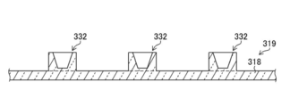
- FIG. 2 is a diagram showing another aspect of the tray.
- a tray 319 shown in FIG. 2 is different from the tray 19 shown in FIG. 1 in that a plate 318 and a lid 332 are integrally formed.
- a tray used in the analysis apparatus 10 as shown in FIG. 2, a tray in which a plate 318 and a lid 332 are integrated can be used.
- the plate 318 and the lid 332 can be manufactured at a time by injection molding, and the lid 332 can be arranged with high accuracy.
- the tray can be manufactured at a low cost.
- the lens 20 transmits fluorescence emitted from the cells 16 by the light output from the fluorescence excitation light source device 12 and transmitted light transmitted through the cells 16 by the light output from the bright field light source device 14. Expanding.
- the lens 20 can be a lens generally used for optical applications.
- the filter group 28 includes an excitation filter 22, a dichroic mirror 24, and a fluorescence filter 26.
- a filter cube For example, Zeiss Filter Set49 (DAPI) can be used.
- the light emitted from the fluorescence excitation light source device 12 transmits only light in the target wavelength region through the excitation filter 22.
- the light transmitted through the excitation filter 22 is reflected by the dichroic mirror 24 toward the tray 19.
- the fluorescence emitted from the cells 16 generated by the excitation light emitted from the fluorescence excitation light source device 12 is imaged by the imaging device 30 via the lens 20, the dichroic mirror 24, and the fluorescence filter 26.
- the fluorescence emitted by the excitation light has a fluorescence wavelength region on the longer wavelength side than the excitation light wavelength region, only the fluorescence emission can be transmitted by using the dichroic mirror 24. Furthermore, by using the fluorescence filter 26 that transmits only the fluorescence without transmitting the excitation light, the imaging device 30 can capture an image with only the information of the fluorescence emitted from the cell 16. Therefore, by transmitting only the fluorescence with the fluorescence filter 26, the image captured by the imaging device 30 can be acquired without being influenced by the excitation light, and the accuracy of the inspection is improved by the fluorescence emission information. Can be made.
- Fluorescence imaging with light emitted from the fluorescence excitation light source device 12 is usually immunostained with a plurality of types of dyes in order to obtain a plurality of information for one cell according to the purpose of cell inspection.
- the fluorescence from each dye of immunostained cells is photographed using a filter group having transmission characteristics or reflection characteristics suitable for the fluorescence wavelength of each dye, so that optical wavelengths of different wavelengths can be obtained. Information can be obtained.
- the transmitted light of the cell 16 with the light source device 14 for bright fields it images with the filter group 28 removed. Thereby, the transmitted light can be imaged by the imaging device 30.
- the imaging device 30 is not particularly limited as long as it can capture the fluorescence or transmitted light of the cells 16 in the lid 32 on the tray 19.
- a CCD (charge-coupled device) camera can be used.
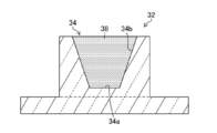
- FIG. 3 is a cross-sectional view showing the shape of the lid 32 of the life science tube used in the present embodiment.
- the material of the lid 32 preferably has conditions such as being transparent to these lights, not being autofluorescent, and not being scattered.
- the bottom surface 34a of the recess 34 of the lid 32 has a flat shape. By flattening the bottom surface 34a of the recess 34, it becomes possible to focus on the cell 16, and image analysis of the cell 16 existing on the bottom surface 34a can be performed with high accuracy.
- the shape of the bottom surface 34a is a circle or a polygon more than a quadrangle. Further, when the size of the bottom surface 34a approximates to a circle circumscribing the bottom surface 34a, the diameter L of the circle is preferably 0.05 mm ⁇ to 1 mm ⁇ , and more preferably 0.1 mm ⁇ to 0.5 mm ⁇ . More preferably, it is 0.2 mm ⁇ or more and 0.4 mm ⁇ or less. In FIG. 3, the bottom surface 34a is described as a circle.
- the imaging of the cells 16 can be performed by performing bright field imaging with fluorescence information from each dye, and superimposing each image after imaging as necessary to analyze the cells.
- FIG. 4 is a diagram showing the relationship between the image capturing area 40 captured by the microscope and the size of the bottom surface 34a of the recess 34.
- the size of the bottom surface 34a is such that the diameter L of the bottom surface 34a is shorter than the length of the short side d among the two orthogonal sides, the long side e, and the short side d of the image capturing region 40, and the length of the short side d. It is preferable to set it to 1/2 or more.
- the flat bottom surface 34a of the lid in which the cells are accommodated can be formed within the image capturing region 40 according to the size of a preferable cell image and 1 It is possible to take a picture of cells in the field of view.
- the size of the image photographing area 40 is determined by the magnification of the objective lens of the microscope and the photographing camera.
- the bottom surface 34a can be imaged by one piece in the image capturing area 40 by setting the diameter L of the bottom surface to 0.4 mm ⁇ . .
- the diameter L of the bottom surface is 0.2 mm ⁇ for a 40 ⁇ objective lens, the diameter L is 0.1 mm ⁇ for a 63 ⁇ objective lens, and the diameter L is 1 mm ⁇ for a 10 ⁇ objective lens.
- the bottom surface 34a can be imaged with one image.
- the magnification is preferably a high magnification.
- the magnification of the objective lens starts to affect the accuracy of image analysis due to unevenness on the back side of the lid 32 and the like, and the magnification of the objective lens is about 20 times. Is preferred.
- the side surface 34b of the concave portion 34 is formed obliquely in a direction extending from the bottom surface 34a toward the opening, and has a tapered shape.
- the thickness t of the bottom surface 34a of the lid 32 is preferably 0.2 mm or more and 1 mm or less. As shown in FIG. 1, since the cell 16 is imaged from the back side (bottom side) of the lid 32, the lens 20 is brought closer to the cell 16 if the thickness of the bottom surface 34a is 1 mm or less. This is preferable because it enables photographing of cells at a high magnification. Further, when the depth is 0.2 mm or more, it becomes possible to set the depth of focus in a narrow range, and even if there is even a slight scratch on the back side of the lid 32, the image of the image that is captured because the focus of the scratch is shifted. A scratch image is not projected, and only a cell image can be taken, which is preferable.
- the thickness t of the bottom surface 34a is more preferably 0.3 mm or more and 0.5 mm or less, and further preferably 0.4 mm.
- the material of the lid 32 is preferably a material that easily transmits light when an image is taken. Specifically, a material selected from acrylic resin, polypropylene, or polystyrene can be used.
- the lid 32 made of these materials preferably has a transmittance for light having a wavelength of 350 nm or more and 800 nm or less of 60% or more, more preferably 70% or more, and further preferably 80% or more. preferable. From the viewpoint of light transmittance, it is preferable to use acrylic resin or polypropylene.
- the surface (bottom surface 34a and side surface 34b) of the recess 34 is subjected to a low cell adhesion treatment.
- the cell low adhesion treatment is treatment for preventing cells, ie, proteins, from adhering to the bottom surface 34a and the side surface 34b in the recess 34, and is a treatment for coating the surface with a material having a property of preventing protein adsorption.
- the cause of protein adsorption into the recess 34 is mainly due to the hydrophobic interaction in which the hydrophobic group on the surface of the resin, which is the material of the lid 32, and the hydrophobic group in the protein bind to each other. It is possible to obtain a surface subjected to a low cell adhesion treatment by coating a material having
- a polymer containing a phosphocholine group for example, Lipidure (registered trademark) (also known as MPC (2-methacryloyloxyethylphosphorylcholine) polymer) (manufactured by NOF Corporation)), polyvinylpyrrolidone, polyethylene glycol, PVA (polyvinyl alcohol) hydrogel, BSA (Bovine serum alcohol), etc.
- a coating method coating can be performed by dipping in a dispersion obtained by dispersing the above materials in a solvent and then drying.
- the solvent for example, in the case of lipid, ethanol can be used. By mixing lipid in ethanol at a ratio of 0.5 wt%, a dispersion is obtained.
- the surface of the recess 34 By subjecting the surface of the recess 34 to low cell adhesion, it is possible to prevent the cells from adhering to the side surface 34b before reaching the bottom surface 34a when sorting cells into the recess 34 by flow cytometry or the like. . Further, after the image analysis, when the cell is moved to the tube, it can be easily moved to the tube without adhering to the bottom surface 34a.
- the low cell adhesion treatment can also be performed by stabilizing an enzyme that decomposes the attached protein.
- FIG. 5 is a cross-sectional view showing the shape of a life science tube lid 132 according to another embodiment.
- Side face of the recess 134 of the lid 132 shown in FIG. 5 is a side has an angle theta B relative to the bottom surface 134a 134b, and, and a side surface 134c having an angle theta C with respect to the bottom surface 134a.
- the side surfaces can be bent in multiple stages and formed by side surfaces 134b and 134c that are two-level inclined surfaces having different angles ⁇ B and ⁇ C with respect to the bottom surface 134a. By forming the side surface with two inclined surfaces, the degree of freedom in designing the side surface in the recess 134 can be increased.
- the side surface is a two-step inclined surface, but the number of steps is not particularly limited, and may be three or more inclined surfaces.
- FIG. 6 is a cross-sectional view showing the shape of a life science tube lid 232 according to still another embodiment.
- the lid 232 shown in FIG. 6 is different from the other embodiments in that a spacer 236 is provided in the recess.
- ⁇ Tube set for life science The lid of the above-described life science tube is used as a life science tube set together with the life science tube.
- tubes for life science use tubes used for applications such as cell culture, detection, separation, purification, analysis and evaluation, and synthesis, detection, separation, purification, analysis and evaluation of compounds containing biomolecules. Can do.
- a low protein adsorption tube that reduces sample adhesion to the container can be used.
- a PCR tube for performing PCR treatment can be used.
- FIG. 7 to 9 are process diagrams showing processes in the cell sorting direction.
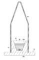
- FIG. 10 is a diagram illustrating a process of attaching a life science tube
- FIG. 11 is a diagram illustrating a process of moving a target cell to the life science tube.
- the step of sorting the cells into the lid of the tube for life science the step of capturing the sorted cells, obtaining the cell image, and the cell image, Selecting a target cell.
- a processing step a processing step.
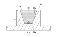
- the culture solution 38 is dropped into the recess 34 of the lid 32.
- the cells 16 are sorted into the recess 34 having the culture solution 38.
- the step of separating target cells from a plurality of cells can be performed, for example, by flow cytometry.
- a sample liquid containing a measurement target substance such as a measurement target cell is flowed to the center side of the laminar flow of the sheath liquid in the flow cell, and the measurement target substance is irradiated with laser light in the optical detection unit, thereby By measuring the generated scattered light and fluorescence, the size and structure of the substance to be measured are measured.
- the measurement parameters in the optical detection unit include forward scattered light, side scattered light, and fluorescence. In forward scattered light, the size of the measurement target is measured, and the structure of the measurement target substance is determined by the side scattered light and fluorescence. Etc. can be measured.
- the target cells are sorted into the lid on the tray by the sorting system.
- the sample / sheath fluid is designed to flow from top to bottom, and it drops out of the nozzle at the tip of the flow cell in laminar flow.
- a vertical vibration is applied to the entire flow cell or the inside of the flow cell by using a transducer (vibrator) so that the sample / sheath liquid that has flowed out of the flow cell becomes a droplet from the middle.
- the sorting conditions using the measurement parameters in the optical detection unit it is determined whether or not the cells are to be sorted, and the whole sample / sheath solution is charged with + or ⁇ just before it becomes a droplet. After that, the droplet falls between the two deflecting plates, the + charged droplet is drawn to the negative plate side, and the negative charged droplet is drawn to the positive plate side, on the tray in the cell collection section.
- Cells can be sorted into each lid.
- FIG. 9 is a diagram illustrating a process of acquiring a cell image.
- the apparatus shown in FIG. 1 can be used as an apparatus for capturing a cell image.
- the lid 32 of the tube for life science used in the present embodiment has a flat bottom surface 34a of the recess 34 and a circular shape or a quadrilateral or more polygonal shape, and the side surface 34b extends from the bottom surface 34a to the opening. It is formed obliquely in the direction that spreads out. Therefore, it is suitable for capturing an image of the cell 16 present on the bottom surface 34a, and a good cell image can be obtained efficiently and efficiently using the lid 32 of the life science tube of the present embodiment.
- Step of selecting target cells includes, for example, the presence or absence of nuclei, the size of the nuclei, the shape of the nuclei (ratio of the area of the nuclear region to the area of the cytoplasm, the degree of circularity of the nuclei), Peak intensity, fluorescence intensity peak value, average value, luminance distribution (whether the cell membrane is uniformly fluorescent or locally intensely fluorescent), the degree of absorption for transmitted light of a specific wavelength (hemoglobin or leukocyte) Determination), spectral characteristics (absorption coefficients with respect to wavelengths of reduced hemoglobin [Hb] and oxidized hemoglobin [HbO 2 ]) resulting from a difference in oxygen affinity of hemoglobin, and the like.
- a viewpoint (cell shape, absorption of transmitted light, etc.) for selecting a target cell and a cell different from the target cell deviated from the selection is determined. Then, the degree of the viewpoint is converted into a numerical value, and from these measured numerical values, a numerical range indicating the probability of being a target cell and a threshold value indicating the range are determined, and the threshold value is determined as a selection reference value.
- a plurality of viewpoints to be selected are determined in advance, and a threshold value for each viewpoint is obtained to determine a selection reference value. Cells that satisfy all of the plurality of reference values thus determined can be selected as target cells. For example, if the target cell is a nucleated red blood cell or the like, the selection method described in International Publication WO2014023093 or International Publication WO2014021311 can be used.
- FIG. 10 is a diagram illustrating a process of attaching a life science tube.
- the tube 50 may be attached only to the lid 32 from which the target cells and the sorted cells 16 are sorted, or the tube 50 may be attached to all the lids 32. .
- the process of attaching the life science tube can be performed using a dedicated device.
- the tube 50 When the tube 50 is attached only to the lid 32 from which the cells 16 sorted out as the target cells are collected, only the target cell to which the tubes 50 are attached performs the next step. Therefore, it is preferable to associate the tube 50 with the information of the cells 16 in the tube 50.
- As a method of associating the information of the cells 16 with the lid 32 or the tube 50 there is a method of marking the arrangement information of the lid 32 arranged on the tray 19 on the lid 32 with characters. As a description example of the arrangement information, if “C4”, it means the fourth row and fourth column of the plate, and if “D4”, it means the fourth column of the D row.
- cell information instead of the arrangement information of the tray 19, cell information may be printed with a QR code (registered trademark).
- RFID radio frequency identifier
- FIG. 11 is a diagram illustrating a process of moving the target cell to the life science tube.
- the cell 16 is moved from the lid 32 to the tube 50 by, for example, moving the cell 16 together with the culture solution 38 into the tube 50 by inverting and centrifuging the tube 50 after attaching the tube 50 to the lid 32. it can.
- the step of moving the cells to the life science tube can be performed using a dedicated device.
- the target cell is processed.
- the process for treating the target cell include PCR treatment.
- the PCR treatment is a method of amplifying a specific region of a DNA (deoxyribonucleic acid) molecule, and can be performed, for example, by the following method.
- the PCR process is not limited to the following method.
- the process of processing the target cell is not limited to the PCR process, and other processes can be performed.
- reaction solution is rapidly cooled to about 60 ° C., the single-stranded DNA and primer are heated (annealed) to a predetermined temperature, and the single-stranded DNA and primer are heated.
- a specific DNA fragment can be amplified by repeating steps 1 to 3 by setting steps 1 to 3 as one cycle. Generally, when the PCR treatment is performed n times, the target portion can be amplified 2n times from one double-stranded DNA. Although long DNA strands remain until the end, the amount of DNA can be reduced to a negligible amount compared to the specific DNA fragment required by performing about 20 cycles.
- the cell sorting method of the present embodiment after the cell image is captured and the target cell is determined using the lid, the cell is moved to the tube and the target cell is processed. it can. Therefore, one life science tube set having a lid can perform from image analysis to cell processing. Further, the movement of the cells from the lid for performing image analysis to the tube for processing can be easily performed without requiring a difficult operation such as using a capillary.
Landscapes
- Life Sciences & Earth Sciences (AREA)
- Chemical & Material Sciences (AREA)
- Health & Medical Sciences (AREA)
- Engineering & Computer Science (AREA)
- Bioinformatics & Cheminformatics (AREA)
- Organic Chemistry (AREA)
- Wood Science & Technology (AREA)
- Zoology (AREA)
- Biotechnology (AREA)
- General Health & Medical Sciences (AREA)
- Biochemistry (AREA)
- Genetics & Genomics (AREA)
- Microbiology (AREA)
- Biomedical Technology (AREA)
- Medicinal Chemistry (AREA)
- General Engineering & Computer Science (AREA)
- Physics & Mathematics (AREA)
- Analytical Chemistry (AREA)
- Immunology (AREA)
- Sustainable Development (AREA)
- General Physics & Mathematics (AREA)
- Pathology (AREA)
- Molecular Biology (AREA)
- Proteomics, Peptides & Aminoacids (AREA)
- Tropical Medicine & Parasitology (AREA)
- Biophysics (AREA)
- Virology (AREA)
- Hematology (AREA)
- Urology & Nephrology (AREA)
- Food Science & Technology (AREA)
- Apparatus Associated With Microorganisms And Enzymes (AREA)
- Measuring Or Testing Involving Enzymes Or Micro-Organisms (AREA)
- Micro-Organisms Or Cultivation Processes Thereof (AREA)
- Investigating Or Analysing Biological Materials (AREA)
- Investigating Or Analysing Materials By Optical Means (AREA)
Abstract
La présente invention concerne un couvercle pour un tube pour les sciences de la vie qui peut être manipulé efficacement, un ensemble de tubes et un procédé de séparation de cellules. L'invention concerne un couvercle 32 qui présente un évidement 34 sur la surface qui se trouve du côté du tube lorsqu'il est fixé, la surface inférieure 34a de l'évidement 34 étant plate et présentant une forme circulaire ou une forme polygonale dotée de quatre côtés ou plus, et une surface latérale 34b comprenant une surface qui est inclinée dans une direction qui s'élargit depuis la surface inférieure 34a vers une ouverture. L'invention concerne en outre un ensemble de tubes constitué par le couvercle 32 et un tube 50 qui est utilisé en combinaison avec celui-ci et un procédé de séparation de cellules utilisant ledit couvercle 32.
Applications Claiming Priority (2)
| Application Number | Priority Date | Filing Date | Title |
|---|---|---|---|
| JP2016064093A JP2019095197A (ja) | 2016-03-28 | 2016-03-28 | ライフサイエンス用チューブの蓋、ライフサイエンス用チューブセットおよび細胞の選別方法 |
| JP2016-064093 | 2016-03-28 |
Publications (1)
| Publication Number | Publication Date |
|---|---|
| WO2017169198A1 true WO2017169198A1 (fr) | 2017-10-05 |
Family
ID=59962938
Family Applications (1)
| Application Number | Title | Priority Date | Filing Date |
|---|---|---|---|
| PCT/JP2017/005200 Ceased WO2017169198A1 (fr) | 2016-03-28 | 2017-02-14 | Couvercle pour tube pour sciences de la vie, ensemble de tubes pour sciences de la vie et procédé de séparation de cellules |
Country Status (2)
| Country | Link |
|---|---|
| JP (1) | JP2019095197A (fr) |
| WO (1) | WO2017169198A1 (fr) |
Citations (3)
| Publication number | Priority date | Publication date | Assignee | Title |
|---|---|---|---|---|
| JP2011072263A (ja) * | 2009-09-30 | 2011-04-14 | Toppan Printing Co Ltd | 遺伝子解析装置 |
| WO2012121225A1 (fr) * | 2011-03-04 | 2012-09-13 | 株式会社カネカ | Procédé de détection d'acide nucléique, et dispositif et kit associés |
| JP2013517809A (ja) * | 2010-01-28 | 2013-05-20 | ザ リージェンツ オブ ザ ユニバーシティ オブ ミシガン | 懸滴装置、懸滴システム、および/または懸滴方法 |
-
2016
- 2016-03-28 JP JP2016064093A patent/JP2019095197A/ja active Pending
-
2017
- 2017-02-14 WO PCT/JP2017/005200 patent/WO2017169198A1/fr not_active Ceased
Patent Citations (3)
| Publication number | Priority date | Publication date | Assignee | Title |
|---|---|---|---|---|
| JP2011072263A (ja) * | 2009-09-30 | 2011-04-14 | Toppan Printing Co Ltd | 遺伝子解析装置 |
| JP2013517809A (ja) * | 2010-01-28 | 2013-05-20 | ザ リージェンツ オブ ザ ユニバーシティ オブ ミシガン | 懸滴装置、懸滴システム、および/または懸滴方法 |
| WO2012121225A1 (fr) * | 2011-03-04 | 2012-09-13 | 株式会社カネカ | Procédé de détection d'acide nucléique, et dispositif et kit associés |
Non-Patent Citations (1)
| Title |
|---|
| STUMPF, F. ET AL.: "Single-cell PCR of genomic DNA enabled by automated single- cell printing for cell isolation", BIOSENSORS AND BIOELECTRONICS, vol. 69, 2015, pages 301 - 306, XP055424735 * |
Also Published As
| Publication number | Publication date |
|---|---|
| JP2019095197A (ja) | 2019-06-20 |
Similar Documents
| Publication | Publication Date | Title |
|---|---|---|
| US12247921B2 (en) | Systems and methods for multicolor imaging | |
| US20220197002A1 (en) | Methods and systems for multidimensional imaging | |
| JP6513802B2 (ja) | ナノ粒子検出のためのレーザー光結合 | |
| US20090011518A1 (en) | Device and Method for Detection of Fluorescence Labelled Biological Components | |
| JP2011510292A (ja) | 液体試料中の粒子を分析するための方法及び装置 | |
| CN116438438A (zh) | 用于基于流动的单颗粒和/或单分子分析的方法和设备 | |
| WO2017169196A1 (fr) | Procédé de criblage de cellules | |
| CN115053118B (zh) | 使用特殊化细胞识别进行循环流式细胞术的装置和方法 | |
| JP2021113806A (ja) | 生体試料を熱サイクルするための装置、それを含む監視機器、およびそのような装置を使用して生体試料を熱サイクルする方法 | |
| US12099178B2 (en) | Kinematic imaging system | |
| JP2017151436A (ja) | 微小ウェルの分析のための光学機器 | |
| EP2951559A1 (fr) | Système de détection à élément optique d'une seule pièce | |
| JP6629429B2 (ja) | 細胞分析システム | |
| CN108779423B (zh) | Pcr用容器 | |
| JP2019095197A (ja) | ライフサイエンス用チューブの蓋、ライフサイエンス用チューブセットおよび細胞の選別方法 | |
| US11060964B2 (en) | Cell detection method | |
| JP7863544B2 (ja) | 多次元撮像のための方法およびシステム | |
| HK40098304A (zh) | 用於多色成像的系统和方法 |
Legal Events
| Date | Code | Title | Description |
|---|---|---|---|
| NENP | Non-entry into the national phase |
Ref country code: DE |
|
| 121 | Ep: the epo has been informed by wipo that ep was designated in this application |
Ref document number: 17773746 Country of ref document: EP Kind code of ref document: A1 |
|
| 122 | Ep: pct application non-entry in european phase |
Ref document number: 17773746 Country of ref document: EP Kind code of ref document: A1 |
|
| NENP | Non-entry into the national phase |
Ref country code: JP |