WO2017169213A1 - Protection anti-vent de microphone-canon - Google Patents
Protection anti-vent de microphone-canon Download PDFInfo
- Publication number
- WO2017169213A1 WO2017169213A1 PCT/JP2017/005382 JP2017005382W WO2017169213A1 WO 2017169213 A1 WO2017169213 A1 WO 2017169213A1 JP 2017005382 W JP2017005382 W JP 2017005382W WO 2017169213 A1 WO2017169213 A1 WO 2017169213A1
- Authority
- WO
- WIPO (PCT)
- Prior art keywords
- space
- microphone
- air
- sound transmission
- gun microphone
- Prior art date
- Legal status (The legal status is an assumption and is not a legal conclusion. Google has not performed a legal analysis and makes no representation as to the accuracy of the status listed.)
- Ceased
Links
Images


Classifications
-
- H—ELECTRICITY
- H04—ELECTRIC COMMUNICATION TECHNIQUE
- H04R—LOUDSPEAKERS, MICROPHONES, GRAMOPHONE PICK-UPS OR LIKE ACOUSTIC ELECTROMECHANICAL TRANSDUCERS; ELECTRIC HEARING AIDS; PUBLIC ADDRESS SYSTEMS
- H04R1/00—Details of transducers, loudspeakers or microphones
- H04R1/08—Mouthpieces; Microphones; Attachments therefor
- H04R1/083—Special constructions of mouthpieces
- H04R1/086—Protective screens, e.g. all weather or wind screens
-
- H—ELECTRICITY
- H04—ELECTRIC COMMUNICATION TECHNIQUE
- H04R—LOUDSPEAKERS, MICROPHONES, GRAMOPHONE PICK-UPS OR LIKE ACOUSTIC ELECTROMECHANICAL TRANSDUCERS; ELECTRIC HEARING AIDS; PUBLIC ADDRESS SYSTEMS
- H04R1/00—Details of transducers, loudspeakers or microphones
- H04R1/08—Mouthpieces; Microphones; Attachments therefor
- H04R1/083—Special constructions of mouthpieces
-
- H—ELECTRICITY
- H04—ELECTRIC COMMUNICATION TECHNIQUE
- H04R—LOUDSPEAKERS, MICROPHONES, GRAMOPHONE PICK-UPS OR LIKE ACOUSTIC ELECTROMECHANICAL TRANSDUCERS; ELECTRIC HEARING AIDS; PUBLIC ADDRESS SYSTEMS
- H04R1/00—Details of transducers, loudspeakers or microphones
- H04R1/08—Mouthpieces; Microphones; Attachments therefor
-
- H—ELECTRICITY
- H04—ELECTRIC COMMUNICATION TECHNIQUE
- H04R—LOUDSPEAKERS, MICROPHONES, GRAMOPHONE PICK-UPS OR LIKE ACOUSTIC ELECTROMECHANICAL TRANSDUCERS; ELECTRIC HEARING AIDS; PUBLIC ADDRESS SYSTEMS
- H04R1/00—Details of transducers, loudspeakers or microphones
- H04R1/20—Arrangements for obtaining desired frequency or directional characteristics
- H04R1/32—Arrangements for obtaining desired frequency or directional characteristics for obtaining desired directional characteristic only
- H04R1/326—Arrangements for obtaining desired frequency or directional characteristics for obtaining desired directional characteristic only for microphones
Definitions
- gun microphones are often used when picking up sound from a distance.
- the gun microphone is a microphone that has a sharp directivity and can pick up the sound that is pointed at the gun microphone by canceling surrounding sounds.
- a gun microphone has an elongated and long cylindrical interference tube. By canceling the sound emitted from the sound source located on the side surface of the gun microphone inside the interference tube and canceling out, it is possible to mainly collect the sound at the tip of the gun microphone.
- the gun microphone has a long interference tube. For this reason, when wind noise such as wind noise is collected using a gun microphone, it is necessary to cover the entire gun microphone including the interference tube with a windshield.
- the windshield provided with the suspension is one in which the suspension is attached with the windshield interposed therebetween. For this reason, the removal becomes complicated, and it is necessary to provide a part of the suspension mechanism not only on the outside of the windshield but also on the inside of the windshield, so that the volume inside the windshield becomes small or the air cannot move sufficiently.
- the function as a windshield has to be reduced.
- the present invention has been made in view of the above points, and an object of the present invention is to provide a gun microphone windshield in which a gripping member can be easily attached and the function as a windshield can be maintained.
- An embodiment of a windshield for a gun microphone according to the present invention is as follows: A first covering that covers a gun microphone (for example, a gun microphone 300 to be described later), has a long shape, and includes a sound transmitting material (for example, a first sound transmitting body 160 to be described later). etc, A second covering body covering the first covering body, and having a long shape and made of an elastic foam having open cells (for example, an outer enclosure 110 described later) )When, A holding portion (for example, a vibration-proof holding portion 120 described later) that engages with the second covering body and is held at a predetermined position of the second covering body, The sound transmitting material is obtained by entanglement of raw materials including fibers.
- the second covering body covers the first covering body for covering the gun microphone.
- the second covering is constituted by an elastic foam having open cells.
- the second cover constitutes a vibration-proof structure, and even when an impact is applied to the holding portion, it is possible to prevent the shock from being absorbed by the second cover and being picked up as noise by the gun microphone.
- the holding part can be easily attached to the second cover by configuring the holding part to engage with the second cover.
- the gripping member can be easily attached, and the function as a windshield can be maintained.
- FIG. 1A shows the outline
- FIG. 5 is an exploded perspective view showing an outer enclosure 110 and a vibration-proof holding unit 120 of the gun microphone windshield 100.
- FIG. 3 is a perspective view showing an outer enclosure 110, a first sound transmission body 160, a microphone holding part 140, and a gun microphone 300 that constitute the gun microphone windshield 100.
- 4 is an enlarged perspective view showing a second end portion 116b of a cylindrical portion 114, a microphone holding portion 140, and a gun microphone 300.
- FIG. 1A shows the outline
- FIG. 5 is an exploded perspective view showing an outer enclosure 110 and a vibration-proof holding unit 120 of the gun microphone windshield 100.
- FIG. 3 is
- FIG. 4 is a perspective view showing a structure of a microphone holding unit 140.
- FIG. It is a perspective view which shows the state which attached the gun microphone 300 to the microphone holding
- FIG. 9 is a cross-sectional view (FIG. 9A) showing the flow of air flowing in the longitudinal direction in the first space SP10 and the second space SP20, and a cross-sectional view (FIG. 9B) showing the flow of air flowing in the circumferential direction.
- FIG. 13 is a cross-sectional view (FIG. 13A) showing the flow of air flowing in the longitudinal direction in the third space SP30 and the second space SP20, and a cross-sectional view (FIG. 13B) showing the flow of air flowing in the circumferential direction.
- FIG. 13A shows the flow of air flowing in the longitudinal direction in the third space SP30 and the second space SP20
- FIG. 13B shows the flow of air flowing in the circumferential direction.
- FIG. 17A which shows the flow of the air which flows into a longitudinal direction in 1st space SP10 and 2nd space SP20 in 3rd Embodiment, and sectional drawing which shows the flow of the air which flows into the circumferential direction (FIG. 17B).
- a first covering 16 that covers the gun microphone 30 (for example, a gun microphone 300 to be described later) and has a long shape and includes a sound transmitting material (for example, a first sound to be described later).
- a transmissive body 160 A second covering 11 that covers the first covering 16 and is formed of an elastic foam having an elongated shape and having open cells (for example, an outer envelope described later) Body 110), A holding part 12 (for example, an anti-vibration holding part 120 described later) that engages with the second covering body 11 and is held at a predetermined position of the second covering body 11,
- the sound transmitting material is provided with a windshield 10 or 20 for a gun microphone including a fiber material obtained by entanglement of raw materials including fibers.
- the gun microphone windshields 10 and 20 are windshields for covering the gun microphone 30.
- the gun microphone 30 has directivity and is a microphone for collecting sounds emitted from a sound source.
- the gun microphone 30 includes an interference tube and the like, and generally has a long shape.
- the gun microphone windshields 10 and 20 include a first cover 16, a second cover 11, and a holding portion 12.
- the first covering body 16 includes a sound transmission material.
- the sound transmission material includes a fiber material.
- the fiber material is obtained by entanglement of raw materials including fibers.
- the sound transmitting material blocks a part of the contacted air and allows the rest to pass. Wind noise such as wind noise can be blocked by the sound transmission material.
- the material and the material of the sound transmission material may be determined so that the wind noise can be accurately blocked and the sound emitted from the sound source can be accurately picked up.
- the sound transmitting material is not easily affected by moisture such as moisture, and can prevent the sound characteristics from changing over time due to moisture.
- the first covering body 16 covers the gun microphone 30.
- the gun microphone 30 generally has a long shape, and an interference opening is formed along the longitudinal direction.
- the first cover 16 may cover the gun microphone 30 so as to cover at least a part of the interference opening. It is preferable to cover the gun microphone 30 so that the first cover 16 covers the entire interference opening.
- the shape of the first cover 16 can be determined according to the shape of the gun microphone 30 having a long shape.
- the length of the first covering body 16 in the longitudinal direction is longer than the length of the gun microphone 30 in the longitudinal direction.
- An air layer can be secured in front of the gun microphone 30 in the sound source direction, and wind noise can be reliably reduced.
- the length of the first cover 16 in the longitudinal direction is preferably the length in the longitudinal direction of the gun microphone 30 plus a length equal to or greater than the diameter of the gun microphone 30.
- the first covering 16 covers the gun microphone 30 so as to accommodate the entire gun microphone 30 except for a cable connected to the gun microphone 30.
- the first covering body 16 is disposed concentrically (coaxially) with the gun microphone 30 to cover the entire gun microphone 30. In particular, in the case of a high-performance windshield intended to cut off or reduce the solid propagation component of wind noise, it is necessary to configure so as not to generate a slight gap.
- the first covering body 16 has a substantially cylindrical shape. Further, the first covering body 16 can be formed not only in a substantially cylindrical shape but also in various tubular shapes such as a rectangular tube shape and an elliptic tube shape. The shape of the first cover 16 can be determined according to the shape of the gun microphone 30 having a long shape.
- the first covering 16 is disposed at a position separated from the gun microphone 30.
- a first space SP ⁇ b> 1 is formed by the gap between the first covering body 16 and the gun microphone 30.
- the distance DT1 between the first cover 16 and the gun microphone 30 may not be constant. It suffices if the first space SP1 is formed between the first covering body 16 and the gun microphone 30 and the wind noise can be blocked by moving the air in the first space SP1.
- the interval DT1 can be made constant.
- the air that has entered the first space SP1 can be evenly dispersed in the first space SP1.
- the second covering body 11 covers the first covering body 16.
- the second covering body 11 has a long shape.
- the second covering body 11 preferably covers the entire first covering body 16.
- the second covering body 11 is composed of an elastic foam having open cells.
- Elastic foam has open cells.
- the elastic foam can control the direction of the air flow by the open bubbles, or can gradually decelerate the air flow by colliding with the open bubbles. Thus, the elastic foam can suppress the direction and speed of the air that has entered the second covering body 11.
- the second space SP2 is formed by the second covering body 11.
- the second covering body 11 controls the air flow in the second space SP2.
- the second covering body 11 is formed of an elastic foam and can be elastically deformed at any location. For this reason, even when an impact is applied from the outside or when wind noise propagates as a solid sound, the impact can be gradually absorbed or reduced by elastically repeating deformation and restoration. .
- the elastic foamed body of the second covering body 11 constitutes a vibration isolation structure.
- the anti-vibration structure of the second covering body 11 can absorb externally applied impacts and the like, make it difficult for the gun microphone 300 to transmit the impacts and prevent the sound from being collected as noise.
- the elastic modulus and the like of the second covering body 11 may be appropriately determined according to the material and thickness of the second covering body 11, the contact area with the holding portion 12, and the like. In order to obtain an anti-vibration effect at 20 Hz-20 kHz, the resonance frequency f 0 of the spring-mass system may be determined to be 10 Hz or less.
- the second covering body 11 is formed of a sponge-like elastic foam having open cells, and has, for example, porosity.
- the surface of the second covering body 11 can be easily engaged with the holding portion 12 described later (easy to be caught), and the second covering body 11 can be easily engaged with the holding portion 12.
- the form of the surface of the second covering body 11 may be any as long as the holding portion 12 can engage with the second covering body 11 and be difficult to come off from the second covering body 11.
- the holding portion 12 is held at a predetermined position of the second covering body 11 by engaging with the second covering body 11. For example, when unevenness is formed on the surface of the second covering body 11, it becomes easy to engage, and the holding portion 12 can be prevented from being detached from the second covering body 11. Further, an adjustment mechanism using bolts and nuts may be added to the holding portion 12 so that the effective diameter can be adjusted to an optimal engagement state.
- the holding unit 12 can be supported by a user's hand, and an impact may be applied to the holding unit 12 during use.
- the second covering body 11 constitutes a vibration-proof structure, and even when an impact is applied to the holding portion 12, the impact is absorbed by the second covering body 11 and the gun microphone 30 is noisy. Can be prevented from being collected.
- the holding part 12 can be easily attached to the second covering 11 by configuring the holding part 12 to engage with the second covering 11.
- First space SP1 and second space SP2> In the second space SP2, the air that has passed through the surface of the second covering body 11 enters the second space SP2.
- the air that has entered the second space SP2 enters the elastic foam.
- the elastic foam has open cells, and the air that has entered the elastic foam moves along the open cells. The direction of the air flow can be controlled by the elastic foam. It is possible to gradually decelerate the air flow by colliding with the open bubbles. Thus, the elastic foam can suppress the speed of air.
- the air that has entered the second space SP2 is gradually decelerated by contact with the first covering body 16, and the momentum of the air can be suppressed.
- the second space SP2 (elastic foam) functions as a buffer region for gradually decelerating the air that has entered. Therefore, the air is difficult to pass through the first covering body 16. However, depending on the environment in which the gun microphone 30 is used, a case where air passes through the first covering body 16 is also assumed. When air passes through the first covering body 16, it also enters the first space SP1.
- First space SP1> In the first space SP1, a longitudinal channel and a circumferential channel are formed.
- the longitudinal flow path is a path along which the air that has flowed into the first space SP1 moves along the longitudinal direction of the first space SP1.
- the first space SP1 has a long shape and functions as a region for facilitating the movement of air in the longitudinal direction. By moving the air in the longitudinal direction, it can be gradually decelerated, and wind noise such as wind noise can be prevented from being collected by the gun microphone 30.
- the circulation channel is a path along which the air that has flowed into the first space SP1 moves along the direction in which the gun microphone 30 circulates. It functions as a region for facilitating the movement of air in the circumferential direction.
- the air can be gradually decelerated by moving it in the circumferential direction.
- the gun microphone windshield 10 functions as a windshield by forming the first space SP1 and the second space SP2. Furthermore, by setting it as such a structure, the 2nd coating
- the holding portion 12 has a surface engaging portion (for example, an annular member 124 described later) that engages with the surface of the second covering body 11.
- the second covering 11 is formed of a sponge-like elastic foam having open cells, and has, for example, porosity.
- the surface of the 2nd covering 11 the thing in which unevenness was formed is preferred. The unevenness on the surface makes it easy to engage with the holding portion 12, and the second covering 11 can be easily engaged with the holding portion 12.
- the holding portion 12 includes a circular engagement portion (for example, an annular member 124 described later) that circulates and engages the second covering body 11.
- the fourth embodiment of the present invention is the same as the first embodiment of the present invention.
- 30 further includes a microphone holding body 14 (for example, a microphone holding unit 140 described later),
- the first covering body has a housing portion (for example, the inside of a first sound transmission body 160 described later) in which the microphone holding body is housed.
- the first space SP ⁇ b> 1 can be formed between the first covering body 16 and the gun microphone 30. .
- the longitudinal flow path and the circulation flow path are stably formed, and the air that has entered the first space SP1 is dispersed in the first space SP1 and gradually decelerated. Can do.
- the fifth embodiment of the present invention is the same as the fourth embodiment of the present invention.
- the microphone holder 14 has a holding member 18 (for example, a holding member 158 described later) that can be elastically deformed by contact with the gun microphone.
- the holding member 18 can be elastically deformed by contact with the gun microphone, even when an impact is applied from the outside, the holding member 18 can absorb the shock, and it is difficult for the gun microphone 30 to transmit the shock and is collected as noise. Can be prevented.
- the vibration-proof structure of the second covering 11 described above it is possible to first absorb the impact, and further to absorb the impact with the holding member 18. In this way, the impact can be mitigated in two stages.
- the sixth embodiment of the present invention is the same as the first embodiment of the present invention.
- a third covering body 26 (for example, a second sound transmission body 260 described later) that can hold the gun microphone 30, has a long shape and includes a sound transmission material, and the first cover
- a third covering body 26 (for example, a second acoustic transmission body 260 described later) that is accommodated in the body 16 and held at a position separated from the first covering body 16 is further provided.
- the third covering body 26 has a long shape.
- the third covering 26 includes a sound transmission material. Wind noise such as wind noise can be further blocked by the third covering body 26.
- the gun microphone 30 can be held on the third covering body 26.
- the gun microphone 30 can be held without using a member for holding the gun microphone 30, and the configuration of the gun microphone windshield 20 can be simplified. In particular, by allowing the gun microphone 30 to be detachably held, the gun microphone 30 can be easily attached and detached.
- the third covering body 26 is held at a position separated from the first covering body 16. Separately from the second space SP2, a third space SP3 is formed between the first covering body 16 and the third covering body 26.
- the second space SP2 functions as described above.
- a case where air passes through the first covering body 16 is also assumed.
- air passes through the first covering body 16 it also enters the third space SP3.
- the longitudinal flow path is a path along which the air flowing into the third space SP3 moves along the longitudinal direction of the third space SP3.
- the third space SP3 has a long shape and functions as a region for facilitating the movement of air in the longitudinal direction. By moving the air in the longitudinal direction, it can be gradually decelerated, and wind noise such as wind noise can be prevented from being collected by the gun microphone 30.
- the circulating flow path is a path along which the air that has flowed into the third space SP3 moves along the direction of circulating around the third covering body 26. It functions as a region for facilitating the movement of air in the circumferential direction.
- the air can be gradually decelerated by moving it in the circumferential direction.
- 3rd space SP3 can be formed with the 3rd covering 26, and the interception nature of a wind noise can further be improved. Further, the gun microphone 30 can be easily attached and held by the third covering body 26.
- the seventh embodiment of the present invention is the same as the sixth embodiment of the present invention.
- a holding member 24 for holding the third covering body 26, which is disposed between the first covering body 16 and the third covering body 26 and is constituted by an elastic foam body having open cells.
- a holding member 24 (for example, an elastic holding body 240 described later) is further provided.
- the third space SP3 is formed between the first covering body 16 and the third covering body 26. It can be formed constant.
- the longitudinal flow path and the circulation flow path are stably formed, and the air that has entered the third space SP3 is dispersed in the third space SP3 and gradually and gradually decelerated. be able to.
- the holding member 24 is configured by an elastic foam having open cells and can be elastically deformed. For this reason, even when an impact is applied from the outside, the impact can be absorbed by the holding member 24, and the impact can be prevented from being transmitted to the gun microphone 30 and can be prevented from being collected as noise.
- the vibration-proof structure of the second covering 11 described above it is possible to first absorb impacts and solid sounds, and further to absorb them with the holding member 24. Thus, impact and wind noise can be mitigated in two stages.
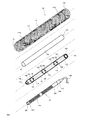
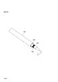
- FIG. 2 is a side view showing the entire gun microphone windshield 100.
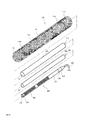
- FIG. 3 is an exploded perspective view showing the outer enclosure 110 and the anti-vibration holding part 120 of the windshield 100 for gun microphone.
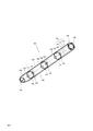
- FIG. 4 is a perspective view showing the outer enclosure 110, the first sound transmission body 160, the microphone holding part 140, and the gun microphone 300 that constitute the gun microphone windshield 100.
- FIG. 5 is an enlarged perspective view showing the second end portion 116 b of the cylindrical portion 114, the microphone holding portion 140, and the gun microphone 300.
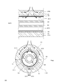
- FIG. 6 is a cross-sectional view showing the configuration of the gun microphone windshield 100 cut in the circumferential direction.
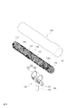
- FIG. 7 is a perspective view showing the structure of the microphone holding unit 140.
- FIG. 8 is a perspective view showing a state in which the gun microphone 300 is attached to the microphone holding unit 140.
- 9 is a cross-sectional view (FIG. 9A) showing the flow of air flowing in the longitudinal direction in the first space SP10 and the second space SP20, and a cross-sectional view showing the flow of air flowing in the circumferential direction (FIG. 9B). ).
- the gun microphone windshield 100 is a windshield used for a so-called gun microphone 300.
- the gun microphone 300 is a microphone that has a sharp directivity, can cancel surrounding sounds, and pick up the sound at the tip of the gun microphone 300.
- the gun microphone 300 has a substantially cylindrical shape and a long and narrow outer shape.
- the gun microphone 300 mainly includes a microphone main body 310 and an interference tube 320.
- the interference tube 320 has an elongated and substantially cylindrical shape.
- the interference tube 320 has a first end 330 and a second end 340 along the longitudinal direction.
- An opening 332 is formed in the first end portion 330.
- a microphone main body 310 having a diaphragm is connected to the second end 340 of the interference tube 320.
- the diaphragm vibrates in response to the sound propagated through the interference tube 320.
- the microphone body 310 converts the vibration of the diaphragm into an electrical signal and outputs it as an audio signal.
- a plurality of slits 350 are formed on the side surface of the interference tube 320. Sound emitted from a sound source located on the side of the gun microphone 300 (interference tube 320) passes through the plurality of slits 350 and enters the inside of the interference tube 320. Sounds that have passed through the plurality of slits 350 interfere with each other inside the interference tube and cancel each other. The sound emitted from the sound source on the side of the gun microphone 300 is not the target of sound collection. It is possible to prevent the sound from passing through the plurality of slits 350 from reaching the microphone body 310 by canceling the sound inside the interference tube. As described above, the gun microphone 300 includes the interference tube 320, so that directivity can be improved and sound can be collected.
- the flow of air such as wind easily touches not only the opening 332 of the gun microphone 300 but also the interference tube 320, and the gun microphone is susceptible to the influence of wind from the side.
- the plurality of slits 350 are formed on the side surface of the interference tube 320, and air such as wind can easily enter the interference tube 320 through the plurality of slits 350.
- the diaphragm of the microphone main body 310 is easily vibrated by the air flow, which causes a so-called wind noise. For this reason, it is necessary for the gun microphone windshield 100 to cover the entire gun microphone 300 including the interference tube 320.
- the windshield 100 for a gun microphone mainly includes an outer enclosure 110, a vibration-proof holding part 120, a first sound transmission body 160, a microphone holding part 140, and a terminal lid. 170.
- the outer enclosure 110, the first sound transmission body 160, and the microphone holding part 140 all have a long shape and are arranged substantially concentrically (substantially coaxial).
- the outer enclosure 110 has a tip end portion 112 and a cylindrical portion 114.
- the tip portion 112 has a substantially hemispherical shape.
- the cylindrical portion 114 has a long cylindrical shape.
- the distal end portion 112 and the cylindrical portion 114 are formed of an elastic foam having open cells, as will be described later, and have sound permeability and allow sound from the outside to pass therethrough.
- the vibration isolation structure can be configured by the outer enclosure 110. Due to the vibration isolation structure of the outer enclosure 110, it is possible to absorb externally applied impacts and the like, making it difficult to be transmitted to the gun microphone 300 and preventing it from being collected as noise.
- the radius of the cylindrical portion 114 is slightly longer than the radius of the first sound transmission body 160. Further, the length of the cylindrical portion 114 in the longitudinal direction is slightly longer than the length of the first acoustic transmission body 160 and the microphone holding portion 140 in the longitudinal direction.
- the cylindrical portion 114 has a first end portion 116a and a second end portion 116b along the longitudinal direction.
- the distal end portion 112 is fixedly attached to the first end portion 116a of the cylindrical portion 114 by adhesion or welding.
- the second end portion 116b is formed with a substantially circular opening.
- a long cavity 118 is formed in the cylindrical portion 114 along the longitudinal direction.
- the first sound transmission body 160 can be inserted into the cavity 118 from the opening of the second end 116b.
- the radius of the cavity 118 slightly smaller than the radius of the first sound transmission body 160
- the first sound transmission body 160 can be inserted into the cavity 118 with the cylindrical portion 114 being slightly elastically deformed.
- the first sound transmission body 160 can be held at a certain position of the cavity 118 by the biasing force generated by the elastic deformation of the cylindrical portion 114 (outer enclosure 110). In this way, by using the outer enclosure 110 formed of an elastic foam, the first acoustic transmission body 160 is held at a fixed position inside the outer enclosure 110 without using a member such as a fixing member. can do.
- the microphone holding unit 140 can be accommodated in the first acoustic transmission body 160.
- the first acoustic transmission body 160 and the microphone holding unit 140 are provided in the cylindrical portion 114 of the outer enclosure 110. Can be stored. In this way, the entire first sound transmission body 160 and the microphone holding part 140 can be covered with the outer enclosure 110.
- the outer enclosure 110 is generally made by foaming a synthetic resin such as polyurethane, and is formed of a sponge-like elastic foam having open cells.
- a synthetic resin such as polyurethane
- fibers made of polyester and cotton can be used as the outer enclosure 110.
- the outer enclosure 110 is formed only of an elastic foam, and the outer shape of the outer enclosure 110 is defined by the shape of the elastic foam.
- the outer enclosure 110 is formed of an elastic foam and has elasticity and can be elastically deformed.
- the cylindrical portion 114 of the outer enclosure 110 has a predetermined thickness T1 in the radial direction.
- the part of thickness T1 is formed of only an elastic foam.
- a long cavity 118 is formed inside the cylindrical portion 114.
- the gun microphone windshield 100 has a first space SP10 and a second space SP20 for processing air that has entered the gun microphone windshield 100.
- the gap between the first sound transmission body 160 and the gun microphone 300 corresponds to the first space SP10
- the cylindrical portion 114 corresponds to the second space SP20
- the second space SP20 is defined by the thickness T1. .
- the functions of the first space SP10 and the second space SP20 will be described later.
- the windshield 100 for a gun microphone has a vibration-proof holding portion 120.
- the anti-vibration holding unit 120 includes a holding body 122 and a gripping unit 130.
- the holding body 122 includes a plurality of annular members 124.
- the annular member 124 has a substantially circular shape and is fitted into the cylindrical portion 114 of the outer enclosure 110.
- the cylindrical portion 114 (outer enclosure 110) is formed of a sponge-like elastic foam having open cells, and the cylindrical portion 114 is porous. For this reason, the surface of the cylindrical portion 114 is rough, and the annular member 124 can be easily engaged with (engaged with) the surface of the cylindrical portion 114, and the annular member 124 can be easily engaged with the cylindrical portion 114.
- the cylindrical portion 114 has a long shape, and even if the annular member 124 slides and moves on the cylindrical portion 114, it does not have to be detached from the cylindrical portion 114.
- the annular member 124 may be easily engaged with the surface of the cylindrical portion 114.
- the roughness of the annular member 124 at a location in contact with the surface of the cylindrical portion 114 is appropriately determined according to the material of the cylindrical portion 114 and the roughness of the eyes. By determining in this way, the annular member 124 can be easily engaged with the surface of the cylindrical portion 114, and the cylindrical portion 114 can be prevented from being damaged by the engagement.
- the radius of the annular member 124 is slightly smaller than the radius of the cylindrical portion 114. For this reason, when the annular member 124 is inserted into the cylindrical portion 114, the cylindrical portion 114 is pressed and elastically deformed by the annular member 124. The annular member 124 is locked to the cylindrical portion 114 by an urging force generated by elastic deformation of the cylindrical portion 114. Further, an adjustment mechanism such as a bolt and a nut may be added to the annular member 124 so that the effective diameter can be adjusted to an optimal engagement state.
- the cylindrical member 114 is not extremely elastically deformed by the annular member 124. By securing the volume of the cylindrical portion 114 and maintaining the second space SP20, the air flow can be attenuated.
- the annular member 124 can be further locked to the cylindrical portion 114 by using not only the engagement due to the roughness of the surface of the cylindrical portion 114 but also the biasing force generated by the elastic deformation of the cylindrical portion 114.
- the annular member 124 has a circular shape
- other shapes may be used.
- the cylindrical portion 114 can be made to circulate in the shape of a belt (band) as an annular member. By increasing the contact area with the cylindrical portion 114, the annular member 124 can be more easily locked to the cylindrical portion 114.
- a protruding portion that protrudes toward the cylindrical portion 114 can be provided.
- a claw-like protrusion can be provided so as to face the cylindrical portion 114.
- the annular member can be easily locked by the cylindrical portion 114.
- the annular member 124 can be easily locked to the cylindrical portion 114 by increasing the contact area with the cylindrical portion 114 or by providing a projection or the like that can be easily engaged with the cylindrical portion 114.
- the holding body 122 can be obtained without processing or deforming the outer enclosure 110 and without changing the acoustic characteristics of the outer enclosure 110. Can be attached to the outer enclosure 110. In addition, since it is configured to be detachable, it can be easily carried and handled.
- a connector (not shown) for connecting an internal cable (not shown) connected to the gun microphone 30 to the outside may be provided in the vibration-proof holding unit 120.
- the electrical signal output from the gun microphone 30 can be output to the outside. It is possible to prevent an impact or solid sound from being transmitted from the cable to the gun microphone 30.
- the internal cable can be carried while being connected to the gun microphone 30, and the handling of the gun microphone windshield 100 can be facilitated. Furthermore, by providing an additional mass (blocking mass) such as lead on the internal cable, impact and solid sound can be more reliably reduced.
- the grip 130 has a grip 132 and a connecting body 134.
- the grip 132 can be gripped by the user.
- a plurality of annular members 124 are connected to the connecting body 134.
- the coupling body 134 holds the grip 132 rotatably.
- the user can position the gun microphone 300 together with the gun microphone windshield 100 toward the desired sound source by holding and supporting the grip portion 130 by hand. Even when the sound source is at a high position or a low position, the gun microphone 300 can be positioned toward the sound source by appropriately determining the angle formed by the coupling body 134 and the grip 132.
- the grip portion 130 is supported by the user's hand, an impact may be applied to the grip portion 130 during use.
- the grip 130 is attached to the outer enclosure 110 by an annular member 124.
- the outer enclosure 110 constitutes an anti-vibration structure, and even when an impact is applied to the grip 130, the outer enclosure 110 absorbs the impact and causes the gun microphone 300 to generate noise (solid propagation sound). The sound can be prevented from being collected.
- the grip portion 130 is a member for indirectly supporting the gun microphone 300 via the outer enclosure 110, and an impact or the like is not easily transmitted directly to the gun microphone 300 due to the vibration isolation structure of the outer enclosure 110. .
- the first sound transmission body 160 is formed by bending a substantially thin plate-shaped sound transmission member into a cylindrical shape.
- the sound transmission member prevents passage of a part of the contacted air. The remaining air that could not be blocked passes through the sound transmission member.
- the sound transmission member will be described in detail later.
- the first sound transmission body 160 has an elongated substantially cylindrical shape. As described above, the radius of the first sound transmission body 160 is formed to be slightly larger than the radius of the cavity 118 of the outer enclosure 110. By doing so, the first acoustic transmission body 160 can be inserted into the cavity 118 by slightly elastically deforming the cylindrical portion 114. The cylindrical portion 114 (outer enclosure 110) is locked to the cylindrical portion 114 by an urging force generated by elastic deformation.
- the sound source side end 162 of the first sound transmission body 160 is closed by a sound transmission member. By closing the end portion 162, the air flowing in through the front end portion 112 of the outer enclosure 110 can hardly enter the inside of the first sound transmission body 160.
- the microphone holding section 140 is connected to the end 164 of the first sound transmission body 160. Is inserted so that the windbreak layer is not interrupted or broken.
- the first sound transmission body 160 is substantially concentric so that the first sound transmission body 160 is covered with the outer enclosure 110 by having such a shape and size. (Coaxial) can be arranged.
- the microphone holding part 140 is disposed along the longitudinal direction inside the first acoustic transmission body 160.
- the radius of the first sound transmission body 160 is set to be slightly larger than the radius of the microphone holding unit 140.
- the gun microphone 300 is stored in the microphone holding unit 140.
- the first sound transmission body 160 has a cylindrical shape, and the length of the first sound transmission body 160 in the longitudinal direction is longer than the length of the gun microphone 300 in the longitudinal direction. For this reason, the gun microphone 300 can be smoothly attached to and detached from the first sound transmission body 160 via the microphone holding unit 140, and the entire gun microphone 300 can be accommodated in the first sound transmission body 160.
- the sound transmission member is made of a fiber material obtained by entanglement of raw materials including fibers, and the air permeability of the fiber material is less than 0.5 s / 100 ml.
- This is a fiber material obtained by entanglement of raw materials that contain 0.5 s / 100 ml of air permeability of the fiber material used as the sound transmission member, and thus has innumerable irregular voids. This is because the density of the fibers is about so that the wind that causes wind noise is blocked.
- the sound transmitting member made of a fiber material functions as a shield or a moving direction changing device (flap) against the “wind” that is the movement of air molecular masses, and the movement of the atmospheric pressure change (the medium itself vibrates). This is because it exhibits almost complete transparency with respect to “sound” that does not move.
- the sound transmission member does not need to be used in combination with other members when the fiber material itself is self-supporting (rigid).
- the sound transmission member has a configuration in which the fiber material is sandwiched between two nets. It may be.
- the sound transmitting member transmits a predetermined frequency range (20 to 20 kHz), and the fiber material constituting the sound transmitting member has an air permeability of less than 0.5 s / 100 ml.
- the air permeability means the time required for a certain amount of air to pass through a certain area under a certain pressure. Here, it is necessary for 100 ml of air to pass through the sheet-like sound-transmitting material. It's time.
- the air permeability is measured by the Gurley method defined in JIS P8117.
- the air permeability of less than 0.5 s / 100 ml means that the measurable range of the apparatus used for the measurement of the present application is 0.5 s / 100 ml or more, and the air permeability of the sound transmitting member is measured by this measurement. This is because it was below the possible range.
- the sound transmission member is obtained by entanglement of raw materials including fibers.
- raw materials including fibers.
- the raw material used for manufacturing the fiber material is a metal fiber or a fluorine fiber.
- the fiber material used as the sound transmission member has a thickness of 3 mm or less, preferably 10 ⁇ m to 2000 ⁇ m, more preferably 20 ⁇ m to 1500 ⁇ m. By setting it as such thickness, an effective wind noise reduction effect can be obtained with a certain degree of rigidity and a minimum simple framework.
- the raw material of the fiber material is not limited to metal fibers or fluorine fibers, and the thickness is not limited to the above values.
- the metal fiber material is obtained by papermaking a slurry containing one or more metal fibers by a wet papermaking method. Yes, when the metal fiber is produced by compression molding, the metal fiber material is obtained by pressing a metal fiber aggregate under heating, and both are metal fiber materials in which the metal fibers are entangled with each other.
- the shape of the metal fiber material is not particularly limited, but a metal fiber sheet is preferable.
- One or more metal fibers that are metal fiber materials are one selected from fibers made of metal materials such as stainless steel, aluminum, brass, copper, titanium, nickel, gold, platinum, and lead. Or it is a combination of two or more.
- the metal fiber material has a structure in which metal fibers are entangled with each other.
- the metal fiber constituting the metal fiber has a fiber diameter of 1 ⁇ m to 50 ⁇ m, preferably 2 ⁇ m to 30 ⁇ m, more preferably 8 ⁇ m to 20 ⁇ m. If it is such a metal fiber, it is suitable for entanglement of the metal fibers, and by entanglement of such metal fibers, the metal fiber sheet having less sound and less sound permeation. It becomes possible.
- the manufacturing method of a metal fiber material by wet papermaking method forms a sheet containing moisture on the net when forming a sheet containing one or more metal fibers by wet papermaking method. And a fiber entanglement process step for entanglement of the metal fibers.
- the fiber entanglement treatment step for example, it is preferable to employ a fiber entanglement treatment step of injecting a high-pressure jet water flow onto the metal fiber sheet surface after papermaking, specifically, a direction orthogonal to the sheet flow direction.
- the metal fibers can be entangled over the entire sheet. That is, for example, by jetting a high-pressure jet water stream in the Z-axis direction of the sheet onto a sheet composed of metal fibers irregularly intersecting the plane direction by wet papermaking, the metal fiber of the portion where the high-pressure jet water stream was jetted Are oriented in the Z-axis direction.
- This metal fiber oriented in the Z-axis direction is entangled between metal fibers irregularly oriented in the plane direction, and each fiber is entangled three-dimensionally, that is, the physical strength can be obtained by entanglement It is.
- the paper making method various methods such as long net paper making, circular net paper making, inclined wire paper making and the like can be adopted as necessary.
- a high viscosity such as polyvinyl pyrrolidone, polyvinyl alcohol, carboxymethyl cellulose (CMC) having a thickening action may be used.
- a small amount of molecular aqueous solution may be added.
- the metal fiber material is manufactured by compression molding. First, the fibers are gathered and preliminarily compressed to form a web, or after a binder is impregnated between the fibers to provide a bond between the fibers, Compress to etc. Thereafter, the metal fiber aggregate is pressed under heating to form a metal fiber sheet.
- the binder is not particularly limited. For example, in addition to organic binders such as acrylic adhesives, epoxy adhesives, and urethane adhesives, inorganic adhesives such as colloidal silica, water glass, and sodium silicate are used. Can be used.
- the surface of the fiber may be preliminarily coated with a heat-adhesive resin, and a metal fiber aggregate may be laminated and heated to be bonded.
- the amount of the binder impregnated is preferably 5 to 130 g, more preferably 20 to 70 g, with respect to the sheet surface weight of 1000 g / m2.
- a sheet is formed by pressing an aggregate of metal fibers under heating.
- the heating conditions are set in consideration of the drying temperature and curing temperature of the binder and the thermoadhesive resin to be used, but the heating temperature is usually about 50 to 1000 ° C.
- the pressurizing pressure is adjusted in consideration of the elasticity of the fiber, the thickness of the sound transmission member, and the light transmittance of the sound transmission member.
- the method for producing a metal fiber material includes a sintering process in which the obtained metal fiber material is sintered at a temperature below the melting point of the metal fiber in a vacuum or in a non-oxidizing atmosphere after the above-described wet papermaking process. It is preferable (in the case of compression molding, heating and pressurizing replace this sintering step). That is, if the sintering process is performed after the wet papermaking process described above, the fiber entanglement process is performed, so there is no need to add an organic binder or the like to the metal fiber material, so the decomposition gas such as the organic binder is sintered. It becomes possible to produce a metal fiber material having a glossy surface peculiar to a metal without any obstacle in the process.
- the strength of the sintered metal fiber material can be further improved. Furthermore, by sintering the metal fiber material, it becomes a material that exhibits high sound permeability and excellent waterproofness. When not sintered, the remaining polymer having a thickening action absorbs water and may have poor waterproofness.
- the fluorine fiber material is a material (paper) composed of short fiber-like fluorine fibers oriented in irregular directions and bonded between the fibers by heat fusion. .
- Fluorine fibers are manufactured from thermoplastic fluororesin, and the main components thereof are polytetrafluoroethylene (PTFE), tetrafluoroethylene (TFE), perfluoroether (PFE), tetrafluoroethylene and hexafluoropropylene.
- PTFE polytetrafluoroethylene
- TFE tetrafluoroethylene
- PFE perfluoroether
- FEP tetrafluoroethylene and hexafluoropropylene.
- the fluorofiber is preferably a single fiber having a fiber length of 1 to 20 mm and a fiber diameter of 2 to 30 ⁇ m in order to form a paper-like material by a wet
- Fluorine fiber material is a mixture of fluorine fiber and a substance having a self-adhesive function by wet papermaking and dried. Can be manufactured by dissolving and removing a substance having a self-adhesive function with a solvent and re-drying if necessary.
- natural pulp made of plant fibers such as wood, cotton, hemp, straw, etc.
- PVA polyvinyl alcohol
- polyester aromatic polyamide
- acrylic polyolefin Synthetic pulp and synthetic fibers made of thermoplastic synthetic polymers
- the sound transmission member of the present invention includes a fiber material obtained by papermaking a raw material containing fibers by a wet papermaking method, and it is sufficient if the air permeability of the fiber material is less than 0.5 s / 100 ml. However, it is not limited to these.
- the sound transmission member has a fiber density enough to have countless irregular voids, and can block the wind that causes wind noise.
- the sound transmission member made of a fiber material functions as a shield against the “wind” that is the movement of air molecular masses, or functions as a moving direction changing device (flap), and moves in the change of atmospheric pressure (the medium itself is It is almost completely transparent to "sound” that only vibrates but does not move.
- the first sound transmission body 160 is composed of such a sound transmission member, and can basically block the wind that causes wind noise.
- the gun microphone 300 is often used outdoors, and is particularly susceptible to the influence of wind from the side.
- the area in contact with the wind must be increased. For this reason, by providing the outer enclosure 110 so as to cover the first sound transmission body 160, it is necessary to form a second space SP20 to be described later and to reliably block the flow of air.
- the microphone holding unit 140 is a member for holding the gun microphone 300. As shown in FIGS. 4, 7, and 8, the microphone holding unit 140 has a long shape and is housed inside the first sound transmission body 160.
- the microphone holding unit 140 includes two straight metal frames 142, a circular tip metal frame 144, three circular metal frames 146, and a terminal metal frame 148.
- the tip metal frame 144 is attached to the tip 152 of the microphone holding part 140.
- the terminal end metal frame 148 is attached to the terminal end 154 of the microphone holding unit 140.
- the straight metal frame 142, the front end metal frame 144, the circulating metal frame 146, and the end metal frame 148 need only have a certain shape, and may be made of metal or resin.
- the frame material diameter is kept as small as 2 mm or less while maintaining rigidity, etc. Is preferable.
- the tip 152 of the microphone holding unit 140 is an end on the side where the first end 330 (opening 332) of the gun microphone 300 is positioned, and the terminal 154 is the second end 340 of the gun microphone 300. Is the end on the side where is positioned.
- the two straight metal frames 142 are arranged in parallel to each other and are in the longitudinal direction of the microphone holding unit 140.
- the two straight metal frames 142 are formed so as to gradually approach each other toward the distal end portion 152, and are connected by the distal end portion 152. By doing in this way, the diameter of the microphone holding part 140 can be formed so as to become gradually smaller toward the tip part 152. It is possible to prevent the gun microphone 300 from falling out of the microphone holding unit 140 and to hold the gun microphone 300 stably.
- the two straight metal frames 142 are connected by the front end metal frame 144.
- the shape of the tip 152 of the microphone holding part 140 can be maintained.
- the opening 332 of the interference tube 320 of the gun microphone 300 is positioned on the tip end metal frame 144.
- the front-end metal frame 144 can dispose the gun microphone 300 without blocking the front of the opening 332, and can accurately collect the sound emitted from the sound source.
- the two straight metal frames 142 are connected to each other by a rotating metal frame 146 at three different positions along the longitudinal direction. By doing so, the two straight metal frames 142 can be prevented from approaching or moving away from each other, and the diameter of the microphone holding part 140 can be kept constant.
- a termination metal frame 148 is connected to the termination 154 of the microphone holding unit 140.
- the end metal frame 148 includes an outer circular metal frame, an inner circular metal frame, and a square metal frame.
- the outer circular metal frame and the inner circular metal frame are arranged concentrically, and the outer circular metal frame is connected to the end portions 154 of the two straight metal frames 142.
- the square metal frame connects the outer circular metal frame and the inner circular metal frame to each other.
- the diameter of the inner circular metal frame is slightly larger than the diameter of the gun microphone 300.
- the gun microphone 300 can be smoothly passed inside the inner circular metal frame.
- the gun microphone 300 can be held on the microphone holding unit 140 without closing the slit 350 formed on the side surface of the interference tube 320. Further, by configuring the microphone holding unit 140 with a metal frame, the microphone holding unit 140 can be reduced in weight, and the gun microphone windshield 100 can be easily handled. Furthermore, by comprising with a metal frame, the rigidity of the microphone holding
- ⁇ Holding member 158> Four holding members 158 are provided in each of the three surrounding metal frames 146.
- the four holding members 158 are arranged so as to face each other, that is, to circulate around the holding members 158 at intervals of about 90 degrees.
- the holding member 158 is made of an elastic member such as rubber.
- a gel-like material made of silicone as a raw material and having flexibility can be used.
- the holding member 158 can be used for buffering or vibration isolation by being elastically deformed.
- the gun microphone 300 When the gun microphone 300 is housed in the microphone holding unit 140, the gun microphone 300 is held by the four holding members 158 provided in each of the three surrounding metal frames 146. The impact is absorbed by the holding member 158, and the impact can be prevented from being collected as noise.
- the guide auxiliary member 150 is an auxiliary member for holding the gun microphone 300.
- the guide auxiliary member 150 includes four resin guide members 156.
- the four guide members 156 are arranged to face each other and to be parallel to the two straight metal frames 142.
- the guide member 156 may have a fixed shape. It may be flexible and deformed.
- the guidance assisting member 150 is a member that guides the gun microphone 300 so that the gun microphone 300 does not protrude from the microphone holding unit 140 when the gun microphone 300 is attached to or detached from the microphone holding unit 140. By providing the guidance assisting member 150, the gun microphone 300 can be smoothly guided along the inside of the microphone holding portion 140.
- the two straight metal frames 142 and the four guide members 156 are arranged along the longitudinal direction of the surface of a virtual long cylinder.
- the virtual long cylinder defines the inner contour of the microphone holding part 140.
- the gun microphone 300 is housed in the microphone holding unit 140, and the microphone holding unit 140 is housed in the first sound transmission body 160.
- the first sound transmission body 160 is accommodated in the cavity 118 of the outer enclosure 110. In this manner, the gun microphone 300, the microphone holding unit 140, and the first sound transmission body 160 are accommodated in the outer enclosure 110.
- the microphone holding unit 140 is housed in the first sound transmission body 160.
- the microphone holding part 140 holds the shape of the first sound transmission body 160 from the inside of the first sound transmission body 160.
- the first sound transmission body 160 is accommodated in the outer enclosure 110. The position of the first sound transmission body 160 is held by the outer enclosure 110.
- the gun microphone 300 is housed in the microphone holding unit 140, and the microphone holding unit 140 is housed in the first sound transmission body 160. Further, the gun microphone 300 is held by the microphone holding unit 140 by the holding member 158.
- the holding member 158 has a predetermined thickness. Depending on the thickness of the holding member 158, the gun microphone 300 is held at a position separated from the two straight metal frames 142. In this way, a gap is formed between the first sound transmission body 160 and the gun microphone 300 inside the first sound transmission body 160, and the first space SP10 is defined by the gap.
- the windshield 100 for gun microphone has a terminal lid 170.
- the end cover 170 is formed of the same material as the outer enclosure 110, blocks the windshield layer by closing the end side of the gun microphone windshield 100, and sets the position of the gun microphone 300 to a predetermined position. Also functions as a stopper to fix.
- the terminal lid 170 has a shape similar to that of the distal end portion 112.
- the end lid 170 is formed of an elastic foam having open cells, and has sound permeability and allows sound from the outside to pass through.
- the terminal lid 170 is attached to the second end 116b of the cylindrical portion 114. By attaching the end lid 170 to the second end 116b of the cylindrical portion 114, the entire gun microphone 300, the microphone holding portion 140, and the first acoustic transmission body 160 are covered with an elastic foam having open cells.
- the windshield 100 for the gun microphone is made.
- first space SP10 ⁇ first space SP10 >> As shown in FIGS. 6, 9A, and 9B, a gap is formed between the first sound transmission body 160 and the gun microphone 300 in the first sound transmission body 160, and a first space SP10 is defined.
- the first space SP10 is a gap having a substantially cylindrical shape as a whole.
- the length along the longitudinal direction of the first space SP10 is determined by the length along the longitudinal direction of the first sound transmission body 160.
- the thickness of the side surface of the first space SP10 is a distance D1 (referred to as a thickness D1 in the diameter direction of the first space SP10) between the first sound transmission body 160 and the gun microphone 300 (FIG. 6). reference).
- the cylindrical portion 114 of the outer enclosure 110 has a thickness T1 in the radial direction (see FIG. 6), and the second space SP20 is defined by the thickness T1.
- the second space SP20 is a gap having a substantially cylindrical shape as a whole.
- the length along the longitudinal direction of the second space SP20 is determined by the length along the longitudinal direction of the cylindrical portion 114.
- the thickness of the side surface of the second space SP20 is the thickness T1 in the radial direction of the cylindrical portion 114 (hereinafter referred to as the thickness T1 in the diameter direction of the second space SP20).
- FIG. 9A is a cross-sectional view showing the flow of air guided along the longitudinal direction in the second space SP20.
- FIG. 9B is a cross-sectional view showing the flow of air guided in the second space SP20 along the circumferential direction (direction of circling the first sound transmission body 160).
- the second space SP20 is an area defined by the cylindrical portion 114 of the outer enclosure 110 and is an area occupied by the elastic foam.
- the air that has passed through the surface of the outer enclosure 110 enters the second space SP20.
- the air that has entered the second space SP20 enters the elastic foam.
- the elastic foam has open cells, and the air that has entered the elastic foam moves along the open cells. The direction of the air flow can be controlled by the elastic foam. Further, the air flow can be prevented by the collision with the open bubbles, and the air can be gradually decelerated. Thus, the elastic foam can suppress the speed of air.
- the air that has entered the second space SP20 travels while being blocked by contact with the first sound transmission body 160.
- the air that has entered the elastic foam gradually decelerates while moving in the second space SP20 while being guided by the first sound transmission body 160.
- the air moving in the second space SP20 moves along the circumferential direction of the component LP20 (see FIG. 9A) moving along the longitudinal direction of the first acoustic transmission body 160 and the first acoustic transmission body 160.
- Component AP20 (see FIG. 9B).
- the second space SP20 is a space that extends in the longitudinal direction according to the length of the gun microphone 300 in the longitudinal direction.
- the length of the second space SP20 in the longitudinal direction can be determined according to the outer shape (length) of the gun microphone 300 to be used.
- the length of the second space SP20 in the longitudinal direction can be a length obtained by adding a length equal to or longer than the diameter of the gun microphone 300 to the length in the longitudinal direction of the gun microphone 300.
- the length can be 10 times or more the diameter of the gun microphone 300, it is preferably 2 to 5 times the diameter of the gun microphone 300.
- the second space SP20 is a region for allowing air to flow in the longitudinal direction, and the air that has entered the second space SP20 can move in the longitudinal direction.
- the second space SP20 is a space in which an area where air can flow in the longitudinal direction is secured, and functions as an air flow buffering area for making it difficult for air to enter the first space SP10.
- the thickness T1 in the diameter direction of the second space SP20 can be determined according to the diameter of the gun microphone 300.
- the thickness T1 in the diameter direction of the second space SP20 can be made smaller than the diameter of the gun microphone 300 or smaller than the radius.
- the thickness T1 in the diameter direction of the second space SP20 may be larger than the diameter of the gun microphone 300.
- the tip is configured to be substantially hemispherical or streamlined.
- the second space SP20 only needs to be able to function as a buffer region for air flow, and the second space SP20 only needs to secure a space that can attenuate the movement of air. It is desirable to configure so that an even air layer can be secured.
- the second space SP20 is a region for allowing air to flow along the circumferential direction, and the air that has entered the second space SP20 can move along the circumferential direction.
- the second space SP20 is a space in which an area where air can be attenuated while flowing in the longitudinal direction and the circumferential direction is secured, and the air flow for making it difficult for the air to enter the first space SP10. Functions as a buffer area.
- FIG. 9A is a cross-sectional view showing the flow of air guided along the longitudinal direction in the first space SP10.
- FIG. 9B is a cross-sectional view showing the flow of air guided along the circumferential direction (direction around the gun microphone 300) in the first space SP10.
- the first space SP10 is an area sandwiched between the first sound transmission body 160 and the gun microphone 300. Unlike the second space SP20, the first space SP10 is not filled with an elastic foam. Depending on the environment in which the gun microphone 300 is used, the first space SP10 may be appropriately filled with an elastic foam.
- the second space SP20 (elastic foam) functions as a buffer region for gradually decelerating the air that has entered the second space SP20. Therefore, the air is difficult to pass through the first sound transmission body 160. However, depending on the environment in which the gun microphone 300 is used, a case where air passes through the first sound transmission body 160 is also assumed. When air passes through the first sound transmission body 160, it also enters the first space SP10.
- the air that has entered the first space SP10 travels while being blocked each time it comes into contact with the first sound transmission body 160 and the gun microphone 300. In this way, the air that has entered the first space SP10 moves in the first space SP10 while being attenuated each time it comes into contact with the first acoustic transmission body 160 and the gun microphone 300.
- the air moving in the first space SP10 is similar to the second space SP20, the component LP10 (see FIG. 9A) moving along the longitudinal direction of the first sound transmission body 160 and the gun microphone 300, and the first And the component AP10 (see FIG. 9B) that moves along the circumferential direction of the gun microphone 300.
- the first space SP10 is a space that extends in the longitudinal direction according to the length of the gun microphone 300 in the longitudinal direction.
- the length of the first space SP10 in the longitudinal direction can be determined according to the outer shape of the gun microphone 300 to be used.
- the length of the first space SP10 in the longitudinal direction can be substantially the same as or slightly longer than the length of the gun microphone 300 in the longitudinal direction, and is approximately twice to five times the diameter of the gun microphone 300. Can be added to the length.
- the first space SP10 is also a region for allowing air to flow in the longitudinal direction, and the air that has entered the first space SP10 can move in the longitudinal direction. That is, the air that has entered the first space SP10 can be gradually decelerated by contact while being guided in the longitudinal direction by the first sound transmission body 160.
- the first space SP10 By securing a space in which the air can sufficiently move in the longitudinal direction by the first space SP10, it is possible to increase the opportunity to gradually decelerate while moving the air, toward the gun microphone 300 from the first space SP10. Air can hardly leak.
- the first space SP10 is also a space in which an area where air can flow in the longitudinal direction is secured, and functions as an air flow buffer area for making it difficult for air to enter the gun microphone 300.
- the thickness D1 in the diameter direction of the first space SP10 can be determined according to the diameter of the gun microphone 300, in consideration of the basic function of the windshield for reducing wind noise and the ease of handling of the gun microphone 300. decide. Basically, wind noise can be reduced to a lower sound range as D1 is larger.
- the diameter D1 of the first space SP10 in the diametrical direction can be made smaller than the diameter of the gun microphone 300 or smaller than the radius.
- the thickness D1 in the diameter direction of the first space SP10 may be larger than the diameter of the gun microphone 300.
- the first space SP10 only needs to be able to function as an air flow buffer region, and the first space SP10 only needs to secure a space in which air can sufficiently move.
- a space in which air can sufficiently move may be determined by a balance between the length in the longitudinal direction of the first space SP10 and the thickness D1 in the diameter direction of the first space SP10. For example, even if the thickness D1 in the diameter direction of the first space SP10 is shortened, it is only necessary to secure a space in which air can sufficiently move by increasing the length in the longitudinal direction of the first space SP10.
- the first space SP10 is a region for allowing air to flow along the circumferential direction, and the air that has entered the first space SP10 can move along the circumferential direction.
- the first space SP10 is a space in which an area where air can flow in the circumferential direction is secured, and functions as an air flow buffer area for making it difficult for air to enter the gun microphone 300.
- the gun microphone windshield 100 has a first space SP10 and a second space SP20, and can sufficiently move the air in the longitudinal direction and decelerate the moved air to absorb negative pressure fluctuations. it can. In this way, the negative pressure fluctuation can be suppressed in stages by causing the first space SP10 and the second space SP20 to function as a two-stage buffer region.
- the windshield 100 for the gun microphone forms the first space SP10 and the second space SP20, it is difficult for air to enter the gun microphone 300, and wind noise caused by the air vibrating the diaphragm is prevented. be able to.
- the diaphragm may be vibrated by negative pressure fluctuation caused by air flowing around the gun microphone 300. Even in such a case, the negative pressure fluctuation can be suppressed by forming the first space SP10 and the second space SP20, and the generation of wind noise due to the negative pressure fluctuation can also be prevented.
- the first space SP10 and the second space SP20 can not only block the movement of air but also suppress the occurrence of fluctuations in negative pressure.
- Second Embodiment >>>
- the gun microphone 300 is held inside the first acoustic transmission body 160 by the microphone holding unit 140 .
- the second sound transmission body 260 is used instead of the microphone holding unit 140.
- the same reference numerals are given to the same components as those in the first embodiment.
- FIG. 10 is a perspective view showing a configuration of a gun / microphone windshield 200 according to the second embodiment.
- FIG. 11 is a perspective view showing the first sound transmission body 160 and the second sound transmission body 260 in the second embodiment.
- FIG. 12 is a perspective view showing an elastic holding body 240 provided between the first sound transmission body 160 and the second sound transmission body 260 in the second embodiment.
- the gun microphone windshield 200 mainly includes an outer enclosure 110, a first acoustic transmission body 160, and a second acoustic transmission body 260.
- the outer enclosure 110 has the same configuration and function as the gun microphone windshield 100 according to the first embodiment.
- the outer enclosure 110 has a front end portion 112 and a cylindrical portion 114.
- the tip portion 112 and the cylindrical portion 114 are formed of an elastic foam having open cells, have sound permeability, and allow sound from the outside to pass through.
- the vibration isolation structure can be configured by the outer enclosure 110. Due to the vibration isolation structure of the outer enclosure 110, it is possible to absorb an impact applied from the outside and prevent it from being transmitted to the gun microphone 300 and being collected as noise.
- a long cavity 118 is formed along the longitudinal direction.
- the first sound transmission body 160 can be inserted into the cavity 118.
- the first sound transmission body 160 can be held at a certain position in the cavity 118 by the urging force generated by the elastic deformation of the cylindrical portion 114.
- the first sound transmission body 160 can be held at a certain position inside the outer enclosure 110 without using a member such as a fixing member.
- the outer enclosure 110 is disposed on the outermost periphery, and the holding body 122 and the grip 130 are arranged on the outer enclosure 110 as in the first embodiment. Can be detachably attached.
- the manner in which the holding body 122 is attached to the outer envelope body 110 is the same as that of the windshield 100 for the gun microphone in the first embodiment (see FIGS. 1 and 2 and the description thereof).
- the holding body 122 can be attached to the outer envelope 110 of the gun microphone windshield 200 according to the second embodiment, and the annular member 124 is locked to the cylindrical portion 114.
- the holder 122 can be attached to the outer envelope 110 without processing or deforming the body 110 and without changing the acoustic characteristics of the outer envelope 110. Moreover, since it is configured to be detachable, it can be easily carried and handled easily.
- the grip portion 130 is supported by the user's hand, an impact may be applied to the grip portion 130 during use.
- the grip 130 is attached to the outer enclosure 110 by an annular member 124. Similar to the first embodiment, the outer enclosure 110 constitutes a vibration-proof structure, and even when an impact is applied to the grip portion 130, the outer enclosure 110 absorbs the impact and causes the gun microphone 300 to generate noise. The sound can be prevented from being collected.
- the grip 130 is a member for indirectly supporting the gun microphone 300 via the outer enclosure 110, and it is possible to make it difficult for an impact or the like to be directly transmitted to the gun microphone 300.
- the first sound transmission body 160 also has the same configuration and function as the gun-microphone windshield 100 according to the first embodiment.
- the first sound transmission body 160 is formed by bending a substantially thin plate-shaped sound transmission member into a cylindrical shape. The sound transmission member prevents passage of a part of the contacted air. The remaining air that could not be blocked passes through the sound transmission member.
- the first sound transmission body 160 has an elongated and substantially cylindrical shape. By slightly elastically deforming the cylindrical portion 114 of the outer enclosure 110, the first sound transmission body 160 can be inserted into the cavity 118, and is locked to the cylindrical portion 114 by the urging force generated by the elastic deformation of the cylindrical portion 114.
- the sound source side end 162 of the first sound transmission body 160 is closed by a sound transmission member. Air that flows in through the front end 112 of the outer enclosure 110 can hardly enter the inside of the first sound transmission body 160.
- the second sound transmission body 260 is formed by bending a substantially thin plate-shaped sound transmission member into a cylindrical shape. The sound transmission member prevents passage of a part of the contacted air. The remaining air that could not be blocked passes through the sound transmission member.
- the second sound transmission body 260 has an elongated and substantially cylindrical shape. As described above, the radius of the second sound transmission body 260 is smaller than the radius of the first sound transmission body 160. By doing in this way, 3rd space SP30 can be formed between the 1st sound transmission body 160 and the 2nd sound transmission body 260.
- FIG. 10 the radius of the second sound transmission body 260 is smaller than the radius of the first sound transmission body 160.
- the sound source side end 262 of the second sound transmission body 260 is also closed by the sound transmission member. It is possible to make it difficult to enter the inside of the second sound transmission body 260.
- the second sound transmission body 260 is formed in such a shape and size so that the second sound transmission body 260 is covered with the first sound transmission body 160. They can be arranged substantially concentrically (coaxially).
- the gun microphone 300 is arranged along the longitudinal direction inside the second sound transmission body 260.
- the radius of the second sound transmission body 260 is set to be slightly larger than the radius of the gun microphone 300.
- An elastic holding body 240 is disposed between the first sound transmission body 160 and the second sound transmission body 260.
- the elastic holder 240 has an annular shape.
- the elastic holder 240 is made of a material that can be elastically deformed.
- the elastic holder 240 can be formed of the same material as that of the outer enclosure 110, for example.
- the elastic holding body 240 has an annular shape, and the elastic holding body 240 can be attached so as to go around the outer periphery of the second acoustic transmission body 260.
- the elastic holding body 240 can be provided at a plurality of different positions along the longitudinal direction of the second sound transmission body 260. With the elastic holding body 240 attached to the second sound transmission body 260, the second sound transmission body 260 is accommodated in the first sound transmission body 160 by being pushed into the first sound transmission body 160. Can do.
- the elastic holding body 240 is elastically deformed to generate a biasing force.
- the second sound transmission body 260 is locked to the first sound transmission body 160 by the generated urging force.
- the first sound transmission body 160 is locked to the cylindrical portion 114 by the urging force generated by the elastic deformation of the cylindrical portion 114.
- the second sound transmission body 260 is locked to the first sound transmission body 160 by an urging force generated by elastic deformation of the elastic holding body 240 attached to the second sound transmission body 260.
- the second sound transmission body 260 By locking the second sound transmission body 260 to the first sound transmission body 160, the second sound transmission body 260 can be prevented from being deformed or displaced, and the first sound transmission body 160 can be prevented. 1st space SP10 can be stably formed between the 2nd sound transmission body 260 and 2nd.
- the elastic holder 240 can be elastically deformed and can absorb an impact even when an impact is applied from the outside. For this reason, it is difficult to be transmitted to the gun microphone 30 and the sound can be prevented from being collected as noise. Due to the elastic deformation of the cylindrical portion 114, the impact can be absorbed first, and further, the impact can be absorbed by the elastic holding body 240. In this way, the impact can be absorbed in two stages.
- a gun microphone 300 is housed inside the second sound transmission body 260.
- the second sound transmission body 260 functions to detachably accommodate and hold the gun microphone 300.
- the second sound transmission body 260 has a cylindrical shape, and the length of the second sound transmission body 260 in the longitudinal direction is longer than the length of the gun microphone 300 in the longitudinal direction. Therefore, the gun microphone 300 can be smoothly attached to and detached from the second sound transmission body 260, and the entire gun microphone 300 can be accommodated in the second sound transmission body 260.
- the second sound transmission body 260 is constituted by a sound transmission member and has a function of preventing wind noise. Moreover, the 2nd sound transmission body 260 has the function to hold
- the first sound transmission body 160 and the second sound transmission body 260 are disposed substantially concentrically and spaced apart from each other.
- the third space SP ⁇ b> 30 can be defined in a region sandwiched between the first sound transmission body 160 and the second sound transmission body 260.
- the third space SP30 is a gap having a substantially cylindrical shape as a whole. The length along the longitudinal direction of the third space SP30 is determined by the length along the longitudinal direction of the first acoustic transmission body 160 and the second acoustic transmission body 260.
- the thickness of the side surface of the third space SP30 is the distance between the first sound transmission body 160 and the second sound transmission body 260 (referred to as the thickness D2 in the diameter direction of the third space SP30). It is determined by the difference between the radius of the first sound transmission body 160 and the radius of the second sound transmission body 260.
- the cylindrical portion 114 of the outer enclosure 110 has a thickness T1 in the radial direction (see FIG. 13B), and the second space SP20 is defined by the thickness T1.
- the second space SP20 is a gap having a substantially cylindrical shape as a whole.
- the length along the longitudinal direction of the second space SP20 is determined by the length along the longitudinal direction of the cylindrical portion 114 and the first sound transmission body 160.
- the thickness of the side surface of the second space SP20 is the thickness T1 in the radial direction of the cylindrical portion 114 (hereinafter referred to as the thickness T1 in the diameter direction of the second space SP20).
- the configuration and function of the second space SP20 are the same as those in the first embodiment.
- FIG. 13A is a cross-sectional view showing the flow of air guided along the longitudinal direction in the third space SP30.
- FIG. 13B is a cross-sectional view showing the flow of air guided in the third space SP30 along the circumferential direction (direction of circling the first sound transmission body 160).
- the third space SP30 is a region sandwiched between the first sound transmission body 160 and the second sound transmission body 260. Unlike the second space SP20, the third space SP30 is not filled with an elastic foam. Note that the third space SP30 may be appropriately filled with an elastic foam depending on the environment in which the gun microphone 300 is used.
- the second space SP20 (elastic foam) functions as a buffer region for gradually decelerating the air that has entered the second space SP20. Therefore, the air is difficult to pass through the second sound transmission body 260. However, depending on the environment in which the gun microphone 300 is used, it may be assumed that air passes through the second sound transmission body 260. When air passes through the second sound transmission body 260, it also enters the third space SP30.
- the third space SP30 is sandwiched between the first sound transmission body 160 and the second sound transmission body 260, and the air that has entered the third space SP30 is in contact with the first sound transmission body 160. Or proceed with being blocked by contact with the second sound transmission body 260. In this way, the air that has entered the third space SP30 moves in the third space SP30 while being attenuated each time it makes contact with the first sound transmission body 160 or the second sound transmission body 260. I will do it.
- the air moving in the third space SP30 is a component LP10 that moves along the longitudinal direction of the first acoustic transmission body 160 and the second acoustic transmission body 260, as in the second space SP20 (see FIG. 13A).
- a component AP10 (see FIG. 13B) that moves along the circumferential direction of the first sound transmission body 160 and the second sound transmission body 260.
- the first sound transmission body 160 and the second sound transmission body 260 have a long shape in accordance with the gun microphone 300 so as to cover the gun microphone 300 in the longitudinal direction.
- the third space SP30 sandwiched between the first sound transmission body 160 and the second sound transmission body 260 also has a long and substantially cylindrical shape, and the third space SP30 includes the gun microphone 300. This space extends in the longitudinal direction according to the length in the longitudinal direction.
- the length of the third space SP30 in the longitudinal direction is substantially the same as that of the second space SP20. Therefore, for example, the length in the longitudinal direction (axial direction) of the third space SP30 can be substantially the same as or slightly longer than the length in the longitudinal direction of the gun microphone 300, and is twice or more than the diameter of the gun microphone 300. The length can be increased by about 5 times.
- the third space SP30 is also a region for allowing air to flow in the longitudinal direction, and the air that has entered the third space SP30 can move in the longitudinal direction. That is, the air that has entered the third space SP30 can be gradually decelerated by the contact while being guided in the longitudinal direction by the first sound transmission body 160 and the second sound transmission body 260.
- the third space SP30 By securing a space in which the air can sufficiently move in the longitudinal direction by the third space SP30, it is possible to increase the opportunity to gradually decelerate while moving the air, from the third space SP30 toward the gun microphone 300. Air can hardly leak.
- the third space SP30 is also a space in which a region where air can flow in the longitudinal direction is secured, and functions as a buffer region for air flow for preventing the air from entering the gun microphone 300.
- the first sound transmission body 160 and the second sound transmission body 260 have a substantially cylindrical shape and cover the gun microphone 300 so as to go around the gun microphone 300. Therefore, the third space SP30 sandwiched between the first sound transmission body 160 and the second sound transmission body 260 also has a substantially cylindrical shape that circulates around the gun microphone 300, and the third space SP30 is It is also a space that covers the gun microphone 300 in the circumferential direction.
- the thickness D2 in the diameter direction of the third space SP30 can be determined according to the diameter of the gun microphone 300.
- the diameter D2 of the third space SP30 in the diametrical direction can be made smaller than the diameter of the gun microphone 300 or smaller than the radius.
- the thickness D2 in the diameter direction of the third space SP30 may be larger than the diameter of the gun microphone 300.
- the third space SP30 can function as a buffer region for air flow.
- the third space SP30 only needs to secure a space in which air can sufficiently move. It is desirable that a substantially uniform air layer be ensured over the entire circumference.
- the size of the third space SP30 may be determined according to the size of the second space SP20. For example, when the size of the second space SP20 is made sufficiently larger than the size of the third space SP30, most of the air flow that has entered the second space SP20 is suppressed by the second space SP20. It is possible not to enter the third space SP30. Further, when the size of the second space SP20 is made smaller than the size of the third space SP30, a part of the air flow that has entered the second space SP20 is suppressed by the second space SP20. It is possible not to enter the third space SP30. The size of the third space SP30 and the size of the second space SP20 can be determined according to the environment in which the gun microphone 300 is used, the structure of the interference tube 320, and the like.
- the third space SP30 is a region for allowing air to flow along the circumferential direction, and the air that has entered the third space SP30 can move along the circumferential direction. That is, the air that has entered the third space SP30 can be gradually decelerated by contact while being guided in the circumferential direction by the first acoustic transmission body 160 and the second acoustic transmission body 260.
- the third space SP30 By securing a space in which the air can sufficiently move in the circumferential direction by the third space SP30, it is possible to increase the opportunity to gradually decelerate while moving the air, toward the gun microphone 300 from the third space SP30. Air can hardly leak.
- the third space SP30 is a space in which an area where air can flow in the circumferential direction is secured, and functions as an air flow buffering area for preventing the air from entering the gun microphone 300.
- Air flow in the third space SP30 has the component LP10 (see FIG. 13A) that moves along the longitudinal direction and the component AP10 (see FIG. 13B) that moves along the circumferential direction.
- the longitudinal component LP10 and the circumferential component AP10 are determined by an angle, a velocity distribution, and the like with respect to the second sound transmission body 260 when entering the third space SP30.
- the air of the component LP10 in the longitudinal direction moves along the longitudinal direction while being blocked by the first sound transmission body 160 and the second sound transmission body 260, and is gradually decelerated by the elastic foam.
- the air of the circumferential component AP10 also moves along the circumferential direction while being blocked by the first sound transmission body 160 and the second sound transmission body 260, and is gradually decelerated by the elastic foam.
- the third space SP30 functions as a buffer region for gradually decelerating the air that has entered the third space SP30.
- the air that has entered the third space SP30 is not only decelerated in the third space SP30, but also flows in the circumferential direction depending on the flow velocity, angle, flow rate, and the like, and then the third space SP30 on the opposite side.
- the second space SP20 may escape (see arrow OP10 in FIG. 13). It is only necessary that the air flowing into the third space SP ⁇ b> 30 is prevented from leaking toward the gun microphone 300 by being blocked by the first sound transmission body 160.
- Wind noise is generated when air (wind) directly hits the diaphragm of the microphone body 310.
- the movement of the air that has entered the second space SP20 is suppressed by the second space SP20 (elastic foam), and further, the air that has entered the third space SP30 by the third space SP30 is suppressed. Suppress movement.
- the movement of air is suppressed by the third space SP30 and the second space SP20, it is difficult for air to leak toward the gun microphone 300, and the movement of air is transmitted to the diaphragm of the microphone body 310 of the gun microphone 300. Thus, wind noise can be prevented.
- the gun microphone windshield 100 can also suppress such negative pressure fluctuations and prevent the generation of wind noise due to negative pressure fluctuations.
- the negative pressure fluctuation can be suppressed by positively causing the movement of air in the longitudinal direction and the movement of air in the circumferential direction.
- the second space SP20 (elastic foam) has a long shape and can sufficiently move air in the longitudinal direction, and the first acoustic transmission body 160, the second acoustic transmission body 260, and elasticity. The moved air can be gradually decelerated by contacting the foam and air.
- the third space SP30 also has a long shape, can sufficiently move air in the longitudinal direction, and the first sound transmitting body 160 and the second sound transmitting body 260 are in contact with air. Thus, the moved air can be gradually decelerated.
- the gun microphone windshield 100 has a third space SP30 and a second space SP20, and can sufficiently move the air in the longitudinal direction and decelerate the moved air to absorb negative pressure fluctuations. it can. Thus, negative pressure fluctuations can be suppressed in stages by causing the third space SP30 and the second space SP20 to function as a two-stage buffer region.
- the windshield 100 for the gun microphone forms the third space SP30 and the second space SP20, it is difficult for air to enter the gun microphone 300, and wind noise caused by the air vibrating the diaphragm is prevented. be able to.
- the diaphragm may be vibrated by negative pressure fluctuation caused by air flowing around the gun microphone 300. Even in such a case, the negative pressure fluctuation can be suppressed by forming the third space SP30 and the second space SP20, and the generation of wind noise due to the negative pressure fluctuation can also be prevented.
- the third space SP30 and the second space SP20 can not only block the movement of air but also suppress the occurrence of fluctuations in negative pressure.
- FIG. 14 is a perspective view showing a configuration of a gun microphone windshield 400 according to the third embodiment.
- FIG. 15 is a perspective view showing the sound transmission body 160 and the gun microphone 300 in the third embodiment.
- FIG. 16 is a perspective view showing an elastic holding body 270 provided between the acoustic currency body 160 and the gun microphone 300 in the third embodiment.
- the gun microphone windshield 400 mainly includes an outer enclosure 110, an acoustic transmission body 160, and an elastic holding body 270.
- the outer enclosure 110 has the same configuration and function as the gun microphone windshield 100 according to the first embodiment.
- the outer enclosure 110 has a front end portion 112 and a cylindrical portion 114.
- the tip portion 112 and the cylindrical portion 114 are formed of an elastic foam having open cells, have sound permeability, and allow sound from the outside to pass through.
- the outer enclosure 110 Since the outer enclosure 110 is formed of an elastic foam, it can be elastically deformed at any location. For this reason, even when an impact is applied from the outside, the impact can be gradually absorbed by repeating elastic deformation and restoration.
- the vibration isolation structure can be configured by the outer enclosure 110. Due to the vibration isolation structure of the outer enclosure 110, it is possible to absorb an impact applied from the outside and make it difficult to be transmitted to the gun microphone 300, thereby preventing noise from being collected.
- a long cavity 118 is formed along the longitudinal direction.
- the first sound transmission body 160 can be inserted into the cavity 118.
- the acoustic transmission body 160 can be held at a certain position in the cavity 118 by the urging force generated by the elastic deformation of the cylindrical portion 114.
- the first sound transmission body 160 can be held at a certain position inside the outer enclosure 110 without using a member such as a fixing member.
- the outer enclosure 110 is disposed on the outermost periphery, and the holding body 122 and the grip portion 130 are arranged on the outer enclosure 110 as in the first embodiment. Can be detachably attached.
- the manner in which the holding body 122 is attached to the outer envelope body 110 is the same as that of the windshield 100 for the gun microphone in the first embodiment (see FIGS. 1 and 2 and the description thereof).
- the holding body 122 can be attached to the outer enclosure 110 of the gun microphone windshield 400 in the third embodiment, and the annular member 124 is locked to the cylindrical portion 114, so that the outer enclosure
- the holder 122 can be attached to the outer envelope 110 without processing or deforming the body 110 and without changing the acoustic characteristics of the outer envelope 110.
- it since it is configured to be detachable, it can be easily carried and handled easily.
- the grip portion 130 is supported by the user's hand, an impact may be applied to the grip portion 130 during use.
- the grip 130 is attached to the outer enclosure 110 by an annular member 124. Similar to the first embodiment, the outer enclosure 110 constitutes a vibration-proof structure, and even when an impact is applied to the grip portion 130, the outer enclosure 110 absorbs the impact and causes the gun microphone 300 to generate noise. The sound can be prevented from being collected.
- the grip 130 is a member for indirectly supporting the gun microphone 300 via the outer enclosure 110, and it is possible to make it difficult for an impact or the like to be directly transmitted to the gun microphone 300.
- the sound transmission body 160 also has the same configuration and function as the gun microphone windshield 100 according to the first embodiment.
- the first sound transmission body 160 is formed by bending a substantially thin plate-shaped sound transmission member into a cylindrical shape. The sound transmission member prevents passage of a part of the contacted air. The remaining air that could not be blocked passes through the sound transmission member.
- the sound transmission body 160 has an elongated and substantially cylindrical shape. By slightly elastically deforming the cylindrical portion 114 of the outer enclosure 110, the sound transmission body 160 can be inserted into the cavity 118, and is locked to the cylindrical portion 114 by the urging force generated by the elastic deformation of the cylindrical portion 114.
- An end 162 on the sound source side of the sound transmission body 160 is closed by a sound transmission member. Air that flows in through the front end 112 of the outer enclosure 110 can hardly enter the inside of the first sound transmission body 160.
- the elastic holder 270 has a cylindrical shape.
- the elastic holder 270 is formed of a material that can be elastically deformed. When the elastic holder 270 is not deformed, the inner diameter of the elastic holder 270 is formed to be shorter than the diameter of the gun microphone 300.
- the length of the elastic holding body 270 may be a length that can stably hold the gun microphone 300 on the sound transmission body 160.
- the elastic holding body 270 can be formed of the same material as that of the outer enclosure 110, for example. By forming the elastic holding body 270 having open cells, the elastic holding body 270 has sound permeability, can pass sound, and can smoothly move air.
- the elastic holder 270 has an annular shape, and the elastic holder 270 can be attached so as to go around the outer periphery of the gun microphone 300.
- the elastic holder 270 can be provided at one or a plurality of positions along the longitudinal direction of the sound transmission body 160. With the elastic holder 270 attached to the gun microphone 300, the gun microphone 300 can be housed in the sound transmitting body 160 by being pushed inside the sound transmitting body 160.
- the elastic holder 270 can pass sound, but is preferably arranged so as not to overlap the slit 350 of the gun microphone 300.
- the elastic holding body 270 is elastically deformed to generate a biasing force.
- the gun microphone 300 is locked to the sound transmission body 160 by the generated urging force.
- the sound transmission body 160 is locked to the cylindrical portion 114 by the urging force generated by the elastic deformation of the cylindrical portion 114.
- the gun microphone 300 By locking the gun microphone 300 to the sound transmission body 160, the gun microphone 300 is prevented from being displaced, and the space SP10 can be stably formed between the sound transmission body 160 and the gun microphone 300.
- the elastic holder 270 can be elastically deformed and can absorb an impact even when an impact is applied from the outside. For this reason, it is difficult to be transmitted to the gun microphone 300 and it is possible to prevent sound from being collected as noise. Due to the elastic deformation of the cylindrical portion 114, the impact can be absorbed first, and further, the impact can be absorbed by the elastic holding body 270. In this way, the impact can be absorbed in two stages.
- First space SP10> As shown in FIGS. 17A and 17B, the sound transmission body 160 and the gun microphone 300 are arranged substantially concentrically and spaced apart from each other. For this reason, a region sandwiched between the sound transmission body 160 and the gun microphone 300 is formed, and a space divided into a plurality of portions can be defined by one or a plurality of elastic holders 270 provided in the gun microphone 300.
- This space has a shape in which the first space SP10 described above is divided into a plurality of spaces by one or more elastic holding bodies 270 provided in the gun microphone 300, and the elastic holding body 270 allows air to flow smoothly. Can function as the first space SP10.
- the cylindrical portion 114 of the outer enclosure 110 has a thickness T1 in the radial direction (see FIG. 1B), and the second space SP20 is defined by the thickness T1.
- the second space SP20 is a gap having a substantially cylindrical shape as a whole.
- the length along the longitudinal direction of the second space SP20 is determined by the length along the longitudinal direction of the cylindrical portion 114 and the first sound transmission body 160.
- the thickness of the side surface of the second space SP20 is the thickness T1 in the radial direction of the cylindrical portion 114 (hereinafter referred to as the thickness T1 in the diameter direction of the second space SP20).
- the configuration and function of the second space SP20 are the same as those in the first embodiment.
- FIG. 17A is a cross-sectional view showing the flow of air guided along the longitudinal direction in the first space SP10.
- FIG. 17B is a cross-sectional view showing the flow of air guided in the first space SP10 along the circumferential direction (direction around the sound transmission body 160).
- the first space SP10 is an area sandwiched between the sound transmission body 160 and the gun microphone 300, and one or more elastic holding bodies 270 exist. Unlike the second space SP20, the first space SP10 is not filled with an elastic foam. Depending on the environment in which the gun microphone 300 is used, the first space SP10 may be appropriately filled with an elastic foam.
- the second space SP20 (elastic foam) functions as a buffer region for gradually decelerating the air that has entered the second space SP20.
- air also enters the first space SP10.
- the first space SP10 is sandwiched between the first sound transmission body 160 and the gun microphone 300, and the air that has entered the first space SP10 is in contact with the first sound transmission body 160 or the elastic holding body 270. It is blocked by contact with and progresses. In this way, the air that has entered the first space SP10 moves through the first space SP10 while being attenuated each time it makes contact with the first acoustic transmission body 160 or with the elastic holding body 270. .
- the air moving in the first space SP10 includes the component LP10 (see FIG. 17A) moving along the longitudinal direction of the first sound transmission body 160 and the gun microphone 300, as in the second space SP20, and the first And the component AP10 (see FIG. 17B) that moves along the circumferential direction of the gun microphone 300.
- the first space SP10 is a space that extends in the longitudinal direction according to the length of the gun microphone 300 in the longitudinal direction.
- the length of the first space SP10 in the longitudinal direction can be determined according to the outer shape of the gun microphone 300 to be used.
- the length of the first space SP10 in the longitudinal direction can be substantially the same as or slightly longer than the length of the gun microphone 300 in the longitudinal direction, and is approximately twice to five times the diameter of the gun microphone 300. Can be added to the length.
- the first space SP10 is also a region for allowing air to flow in the longitudinal direction, and the air that has entered the first space SP10 can move in the longitudinal direction. That is, the air that has entered the first space SP10 can be gradually decelerated by contact with the first sound transmission body and the elastic holding body 270 while being guided in the longitudinal direction by the first sound transmission body 160. .
- Air can hardly leak.
- the first space SP10 is also a space in which an area where air can flow in the longitudinal direction is secured, and functions as an air flow buffer area for making it difficult for air to enter the gun microphone 300.
- the thickness D1 in the diameter direction of the first space SP10 can be determined according to the diameter of the gun microphone 300, in consideration of the basic function of the windshield for reducing wind noise and the ease of handling of the gun microphone 300. decide. Basically, wind noise can be reduced to a lower sound range as D1 is larger.
- the diameter D1 of the first space SP10 in the diametrical direction can be made smaller than the diameter of the gun microphone 300 or smaller than the radius.
- the thickness D1 in the diameter direction of the first space SP10 may be larger than the diameter of the gun microphone 300.
- the first space SP10 only needs to be able to function as an air flow buffer region, and the first space SP10 only needs to secure a space in which air can sufficiently move.
- a space in which air can sufficiently move may be determined by a balance between the length in the longitudinal direction of the first space SP10 and the thickness D1 in the diameter direction of the first space SP10. For example, even if the thickness D1 in the diameter direction of the first space SP10 is shortened, it is only necessary to secure a space in which air can sufficiently move by increasing the length in the longitudinal direction of the first space SP10.
- the first space SP10 is a region for allowing air to flow along the circumferential direction, and the air that has entered the first space SP10 can move along the circumferential direction.
- the first space SP10 is a space in which an area where air can flow in the circumferential direction is secured, and functions as an air flow buffer area for making it difficult for air to enter the gun microphone 300.
- the gun microphone windshield 400 has a first space SP10 and a second space SP20, and can sufficiently move the air in the longitudinal direction and decelerate the moved air to absorb negative pressure fluctuations. it can. Thus, negative pressure fluctuations can be suppressed in stages by causing the first space SP10 and the second space SP20 to function as a two-stage buffer region.
- the windshield 400 for the gun microphone forms the first space SP10 and the second space SP20, it is difficult for air to enter the gun microphone 300, and wind noise caused by the air vibrating the diaphragm is prevented. be able to.
- the diaphragm may be vibrated by negative pressure fluctuation caused by air flowing around the gun microphone 300. Even in such a case, the negative pressure fluctuation can be suppressed by forming the first space SP10 and the second space SP20, and the generation of wind noise due to the negative pressure fluctuation can also be prevented.
- the first space SP10 and the second space SP20 can not only block the movement of air but also suppress the occurrence of fluctuations in negative pressure.
- a third sound transmission body that covers the entire outer peripheral body 110 or the peripheral surface is provided, and the third sound transmission body is used as the outermost peripheral body so that the vibration isolation holding portion 120 is locked to the third sound transmission body. It may be.
- the third sound transmission body has an elongated substantially cylindrical shape.
- the diameter of the third sound transmission body is slightly larger than the diameter of the outer enclosure 110.
- the length of the third sound transmission body in the longitudinal direction is longer than the length of the outer enclosure 110 in the longitudinal direction.
- the sound source side end of the third sound transmission member may be closed with a sound transmission member. The inflow of air to the front end 112 of the outer enclosure 110 can be prevented.
- the third sound transmission body is also formed by bending a substantially thin plate-shaped sound transmission member into a cylindrical shape.
- the sound transmission member prevents passage of a part of the contacted air.
- waterproofness can be improved by using the sound transmission member which sintered the metal fiber material.
- the annular member 124 of the anti-vibration holding unit 120 may be easily engaged according to the shape and properties of the surface of the third sound transmission body. For example, it is preferable that the roughness of the annular member 124 at a location in contact with the surface of the third sound transmission body is appropriately determined according to the material and roughness of the third sound transmission body. In particular, the annular member 124 is preferably determined according to the cushioning property of the third sound transmission body. By defining in this way, it is possible to easily engage the annular member 124 with the surface of the third sound transmission body, while preventing the third sound transmission body and the cylindrical portion 114 from being damaged by the engagement.
- the outer enclosure 110 can be protected by providing a third sound transmission body that covers the entire outer circumference 110 or the peripheral surface thereof.
- the sound transmission member obtained by sintering the metal fiber material is highly waterproof, and can protect the outer enclosure 110 from moisture such as moisture. That is, even when the gun microphone windshields 100 and 200 are used in an environment with high humidity such as rain, the outer enclosure 110 is covered with the third acoustic transmission body, and the third acoustic transmission body is used as the outermost peripheral body. The characteristics of the enclosure 110 can be maintained.
- a sheet-shaped windshield enclosure 180 that completely covers the entire outer surface of the outer enclosure 110 described above can be provided to provide the outermost periphery. It is possible to prevent deterioration over time by protecting the outer enclosure 110 from physical impact and protecting it from moisture such as ultraviolet rays such as sunlight and moisture. Moreover, the inflow of air into the windshield can be prevented, and the entry of dust and the generation of noise can be suppressed.
- the material of the sheet-shaped windshield enclosure 180 is not particularly limited, but is preferably a material excellent in weather resistance and sound transmission, for example, the above-described sound transmission sheet is preferable, and a fiber sheet such as a metal fiber sheet or a fluorine fiber sheet. A sound transmission sheet using is more preferable.
- the thickness of the sheet-shaped windshield enclosure 180 is not particularly limited, but if it is thick, it becomes difficult to fix or seal the sheet-shaped windshield enclosure 180, and if it is thin, the physical strength is weakened.
- the sheet-like windshield enclosure 180 is preferably flexible so that it can be deformed to cover the outer surface of the outer enclosure 110.
- the shape of the sheet-shaped windshield enclosure 180 is not particularly limited as long as the entire outer surface of the outer enclosure 110 can be completely covered.
- the sheet-like windshield enclosure 180 has an elongated and substantially cylindrical shape that matches the shape of the outer enclosure 110, and is preferably a bag-like form.
- the sheet-shaped windshield enclosure 180 can close the opening 181 after the gun-microphone windshield 100 is included.
- the closing method is not particularly limited, and examples thereof include a suturing method and an adhesive method.
- a method for fixing the sheet-shaped windshield enclosure 180 to the outer enclosure 110 is not particularly limited, and a bonding method using an adhesive for the outer enclosure 110 and the sheet-like enclosure 180 or an outer side of the vibration-proof holding unit 120 by the annular member 124. The method by tightening from is mentioned.
- the outer enclosure 110 and the sheet-shaped windshield enclosure 180 may be fixed by closely contacting the outer enclosure 110 and the sheet-shaped windshield enclosure 180, and between the outer enclosure 110 and the sheet-shaped windshield enclosure 180.
- a space may be provided and fixed. This space is a space in which an area where air can flow in the longitudinal direction of the outer enclosure 110 is secured, and functions as an air flow buffering area for making it difficult for air to enter the gun microphone 300.
- the annular member 124 of the anti-vibration holding unit 120 may be held on the surface of the sheet-shaped windshield enclosure. What is necessary is just to make it easy to hold
- the roughness of the annular member 124 at a location in contact with the surface of the sheet-shaped windshield enclosure 180 is appropriately determined according to the material and roughness of the sheet-shaped windshield enclosure.
- the annular member 124 is preferably determined according to the cushioning property of the outermost peripheral body. By determining in this way, it is possible to prevent the outer envelope body 110 and the cylindrical portion 114 from being damaged by the gripping while making it easy to grip the annular member 124 with the surface of the sheet-shaped windshield enclosure.
- Gun microphone windshield (Gun microphone windshield 10) 110 Outer enclosure (second covering body 11) 120 Anti-vibration holding part (holding part 12) 124 annular member (surface engaging part) 130 Grasping part 140 Microphone holding part (microphone holding body 14) 158 Holding member (holding member 18) 160 1st sound transmission body (1st coating body 16) 170 Terminal lid 180 Sheet-shaped windshield enclosure 200 Gunmic windshield (Gunmic windshield 20) 240 Elastic holder (holding member 24) 260 Second sound transmission body (third covering body 26) 270 Elastic holder 300 Gun microphone (Gun microphone 30) 400 Windshield for gun microphone SP10 1st space (1st space SP1) SP20 2nd space (2nd space SP2) SP30 3rd space (3rd space SP3)
Landscapes
- Physics & Mathematics (AREA)
- Engineering & Computer Science (AREA)
- Acoustics & Sound (AREA)
- Signal Processing (AREA)
- Health & Medical Sciences (AREA)
- Otolaryngology (AREA)
- Details Of Audible-Bandwidth Transducers (AREA)
Abstract
Priority Applications (3)
| Application Number | Priority Date | Filing Date | Title |
|---|---|---|---|
| EP17773761.6A EP3439319A4 (fr) | 2016-03-29 | 2017-02-14 | Protection anti-vent de microphone-canon |
| US16/088,384 US20190268685A1 (en) | 2016-03-29 | 2017-02-14 | Gun microphone wind shield |
| JP2018508538A JPWO2017169213A1 (ja) | 2016-03-29 | 2017-02-14 | ガンマイク用風防 |
Applications Claiming Priority (2)
| Application Number | Priority Date | Filing Date | Title |
|---|---|---|---|
| JP2016065177 | 2016-03-29 | ||
| JP2016-065177 | 2016-03-29 |
Publications (1)
| Publication Number | Publication Date |
|---|---|
| WO2017169213A1 true WO2017169213A1 (fr) | 2017-10-05 |
Family
ID=59963909
Family Applications (1)
| Application Number | Title | Priority Date | Filing Date |
|---|---|---|---|
| PCT/JP2017/005382 Ceased WO2017169213A1 (fr) | 2016-03-29 | 2017-02-14 | Protection anti-vent de microphone-canon |
Country Status (4)
| Country | Link |
|---|---|
| US (1) | US20190268685A1 (fr) |
| EP (1) | EP3439319A4 (fr) |
| JP (1) | JPWO2017169213A1 (fr) |
| WO (1) | WO2017169213A1 (fr) |
Families Citing this family (4)
| Publication number | Priority date | Publication date | Assignee | Title |
|---|---|---|---|---|
| USD963272S1 (en) * | 2019-08-28 | 2022-09-06 | Brenda Stone | Water spill management apparatus |
| US11082764B1 (en) * | 2020-08-06 | 2021-08-03 | Beijing Kuzhi Technology Co., Ltd. | Microphone and speaker all-in-one machine |
| EP4331236A4 (fr) * | 2021-04-30 | 2025-02-26 | Zipline International Inc. | Coiffe de réduction de bruit pour aéronef |
| USD1027918S1 (en) * | 2022-08-29 | 2024-05-21 | Ningbo Yinzhou Luxsound Electronics Co., Ltd. | Microphone isolation shield |
Citations (5)
| Publication number | Priority date | Publication date | Assignee | Title |
|---|---|---|---|---|
| JPS6356895U (fr) * | 1986-10-01 | 1988-04-15 | ||
| JPS63165995U (fr) * | 1987-04-20 | 1988-10-28 | ||
| JPH0262889U (fr) * | 1988-10-31 | 1990-05-10 | ||
| JPH1098791A (ja) * | 1996-08-30 | 1998-04-14 | Carrier Corp | 音響検出用気体力学多段乱れシールド |
| JP2001091351A (ja) * | 1999-09-21 | 2001-04-06 | Kobayashi Rigaku Kenkyusho | 音検出装置及びこれを用いた騒音計 |
Family Cites Families (14)
| Publication number | Priority date | Publication date | Assignee | Title |
|---|---|---|---|---|
| US2520706A (en) * | 1948-01-30 | 1950-08-29 | Rca Corp | Windscreen for microphones |
| US3095484A (en) * | 1959-10-22 | 1963-06-25 | Electro Voice | Unidirectional microphone |
| US4600077A (en) * | 1985-01-25 | 1986-07-15 | Drever Leslie C | Microphone wind shroud |
| JP2562295B2 (ja) * | 1985-11-19 | 1996-12-11 | 株式会社 オ−デイオテクニカ | 狭指向性マイクロホン |
| US20070195983A1 (en) * | 2005-04-07 | 2007-08-23 | Manfred Klemme | Combination wind screen and microphone shock mount |
| US20060227991A1 (en) * | 2005-04-07 | 2006-10-12 | Manfred Klemme | Combination wind screen and microphone shock mount |
| JP5081459B2 (ja) * | 2007-01-29 | 2012-11-28 | 株式会社オーディオテクニカ | ウインドスクリーンおよび同ウインドスクリーンを備えた狭指向性マイクロホン |
| JP4926885B2 (ja) * | 2007-08-24 | 2012-05-09 | 株式会社オーディオテクニカ | 狭指向性マイクロホン |
| US9221593B2 (en) * | 2009-04-23 | 2015-12-29 | Jeremy R. Kay | Stashable storage tube |
| US8499484B2 (en) * | 2011-02-17 | 2013-08-06 | LW Schneider Incorporated | Assembly for mounting on a picatinny-type rail |
| JP2012175379A (ja) * | 2011-02-21 | 2012-09-10 | Sony Corp | ウインドスクリーン及びマイクロフォン |
| KR101942133B1 (ko) * | 2012-03-21 | 2019-01-24 | 가부시키가이샤 도모에가와 세이시쇼 | 마이크로폰 장치, 마이크로폰 유닛, 마이크로폰 구조 및 이를 이용한 전자 기기 |
| US20170026731A1 (en) * | 2014-02-28 | 2017-01-26 | Tomoegawa Co., Ltd. | Pop noise reduction tool, microphone equipped therewith, pop noise measurement method, and pop noise measurement device |
| US9712904B1 (en) * | 2016-03-29 | 2017-07-18 | Bby Solutions, Inc. | Multi-mode microphone |
-
2017
- 2017-02-14 US US16/088,384 patent/US20190268685A1/en not_active Abandoned
- 2017-02-14 WO PCT/JP2017/005382 patent/WO2017169213A1/fr not_active Ceased
- 2017-02-14 JP JP2018508538A patent/JPWO2017169213A1/ja active Pending
- 2017-02-14 EP EP17773761.6A patent/EP3439319A4/fr not_active Withdrawn
Patent Citations (5)
| Publication number | Priority date | Publication date | Assignee | Title |
|---|---|---|---|---|
| JPS6356895U (fr) * | 1986-10-01 | 1988-04-15 | ||
| JPS63165995U (fr) * | 1987-04-20 | 1988-10-28 | ||
| JPH0262889U (fr) * | 1988-10-31 | 1990-05-10 | ||
| JPH1098791A (ja) * | 1996-08-30 | 1998-04-14 | Carrier Corp | 音響検出用気体力学多段乱れシールド |
| JP2001091351A (ja) * | 1999-09-21 | 2001-04-06 | Kobayashi Rigaku Kenkyusho | 音検出装置及びこれを用いた騒音計 |
Non-Patent Citations (1)
| Title |
|---|
| See also references of EP3439319A4 * |
Also Published As
| Publication number | Publication date |
|---|---|
| EP3439319A1 (fr) | 2019-02-06 |
| US20190268685A1 (en) | 2019-08-29 |
| EP3439319A4 (fr) | 2019-11-13 |
| JPWO2017169213A1 (ja) | 2019-02-07 |
Similar Documents
| Publication | Publication Date | Title |
|---|---|---|
| US9467760B2 (en) | Microphone device, microphone unit, microphone structure, and electronic equipment using these | |
| WO2017169213A1 (fr) | Protection anti-vent de microphone-canon | |
| US10814966B2 (en) | Shroud for an aircraft | |
| US11536411B2 (en) | Silencing tubular structure body | |
| US10854183B2 (en) | Soundproof structure | |
| JP6043407B2 (ja) | 防音構造、及び防音構造の製造方法 | |
| EP3310198B1 (fr) | Casque de protection | |
| CN107925806B (zh) | 音响装置 | |
| JP2020530913A (ja) | シュラウド | |
| WO2013038915A1 (fr) | Matière transmettant le son, structure de surface de commande acoustique utilisant ladite matière et ayant des applications comprenant une construction, un pare-vent de microphone, une grille protectrice, un écran de cinéma transmettant le son et un haut-parleur | |
| EP3094104A1 (fr) | Outil de réduction du bruit de claquement, microphone en étant équipé, procédé de mesure du bruit de claquement et dispositif de mesure de bruit de claquement | |
| CN110024023A (zh) | 防音结构 | |
| JP2012060544A (ja) | マイクロホン用風防及びマイクロホン装置 | |
| JP6651396B2 (ja) | ガンマイク用風防 | |
| US6560345B1 (en) | Microphone | |
| US10861432B2 (en) | Soundproof structure and opening structure | |
| CN217323941U (zh) | 一种具有防霉性能的隔音棉 | |
| CN212684932U (zh) | 多结构复合材料声学阻尼膜及含有该阻尼膜的组件 | |
| JP2015139134A (ja) | 撥水性を有する多孔質材及びこれを用いた音響透過材。 | |
| KR200380429Y1 (ko) | 마이크로폰의 노이즈 감소장치 | |
| KR20060083495A (ko) | 마이크로폰의 노이즈 감소장치 | |
| JP2009169299A (ja) | 吸音体、吸音体群および音響室 |
Legal Events
| Date | Code | Title | Description |
|---|---|---|---|
| ENP | Entry into the national phase |
Ref document number: 2018508538 Country of ref document: JP Kind code of ref document: A |
|
| NENP | Non-entry into the national phase |
Ref country code: DE |
|
| WWE | Wipo information: entry into national phase |
Ref document number: 2017773761 Country of ref document: EP |
|
| ENP | Entry into the national phase |
Ref document number: 2017773761 Country of ref document: EP Effective date: 20181029 |
|
| 121 | Ep: the epo has been informed by wipo that ep was designated in this application |
Ref document number: 17773761 Country of ref document: EP Kind code of ref document: A1 |