WO2017169256A1 - Dispositif de transport utilisant un chariot - Google Patents
Dispositif de transport utilisant un chariot Download PDFInfo
- Publication number
- WO2017169256A1 WO2017169256A1 PCT/JP2017/005826 JP2017005826W WO2017169256A1 WO 2017169256 A1 WO2017169256 A1 WO 2017169256A1 JP 2017005826 W JP2017005826 W JP 2017005826W WO 2017169256 A1 WO2017169256 A1 WO 2017169256A1
- Authority
- WO
- WIPO (PCT)
- Prior art keywords
- carriage
- drive
- transport
- cart
- stopper
- Prior art date
- Legal status (The legal status is an assumption and is not a legal conclusion. Google has not performed a legal analysis and makes no representation as to the accuracy of the status listed.)
- Ceased
Links
Images


Classifications
-
- B—PERFORMING OPERATIONS; TRANSPORTING
- B65—CONVEYING; PACKING; STORING; HANDLING THIN OR FILAMENTARY MATERIAL
- B65G—TRANSPORT OR STORAGE DEVICES, e.g. CONVEYORS FOR LOADING OR TIPPING, SHOP CONVEYOR SYSTEMS OR PNEUMATIC TUBE CONVEYORS
- B65G17/00—Conveyors having an endless traction element, e.g. a chain, transmitting movement to a continuous or substantially-continuous load-carrying surface or to a series of individual load-carriers; Endless-chain conveyors in which the chains form the load-carrying surface
- B65G17/12—Conveyors having an endless traction element, e.g. a chain, transmitting movement to a continuous or substantially-continuous load-carrying surface or to a series of individual load-carriers; Endless-chain conveyors in which the chains form the load-carrying surface comprising a series of individual load-carriers fixed, or normally fixed, relative to traction element
- B65G17/123—Conveyors having an endless traction element, e.g. a chain, transmitting movement to a continuous or substantially-continuous load-carrying surface or to a series of individual load-carriers; Endless-chain conveyors in which the chains form the load-carrying surface comprising a series of individual load-carriers fixed, or normally fixed, relative to traction element arranged to keep the load-carriers horizontally during at least a part of the conveyor run
-
- B—PERFORMING OPERATIONS; TRANSPORTING
- B61—RAILWAYS
- B61B—RAILWAY SYSTEMS; EQUIPMENT THEREFOR NOT OTHERWISE PROVIDED FOR
- B61B10/00—Power and free systems
-
- B—PERFORMING OPERATIONS; TRANSPORTING
- B65—CONVEYING; PACKING; STORING; HANDLING THIN OR FILAMENTARY MATERIAL
- B65G—TRANSPORT OR STORAGE DEVICES, e.g. CONVEYORS FOR LOADING OR TIPPING, SHOP CONVEYOR SYSTEMS OR PNEUMATIC TUBE CONVEYORS
- B65G17/00—Conveyors having an endless traction element, e.g. a chain, transmitting movement to a continuous or substantially-continuous load-carrying surface or to a series of individual load-carriers; Endless-chain conveyors in which the chains form the load-carrying surface
- B65G17/002—Conveyors having an endless traction element, e.g. a chain, transmitting movement to a continuous or substantially-continuous load-carrying surface or to a series of individual load-carriers; Endless-chain conveyors in which the chains form the load-carrying surface comprising load carriers resting on the traction element
-
- B—PERFORMING OPERATIONS; TRANSPORTING
- B65—CONVEYING; PACKING; STORING; HANDLING THIN OR FILAMENTARY MATERIAL
- B65G—TRANSPORT OR STORAGE DEVICES, e.g. CONVEYORS FOR LOADING OR TIPPING, SHOP CONVEYOR SYSTEMS OR PNEUMATIC TUBE CONVEYORS
- B65G17/00—Conveyors having an endless traction element, e.g. a chain, transmitting movement to a continuous or substantially-continuous load-carrying surface or to a series of individual load-carriers; Endless-chain conveyors in which the chains form the load-carrying surface
- B65G17/12—Conveyors having an endless traction element, e.g. a chain, transmitting movement to a continuous or substantially-continuous load-carrying surface or to a series of individual load-carriers; Endless-chain conveyors in which the chains form the load-carrying surface comprising a series of individual load-carriers fixed, or normally fixed, relative to traction element
- B65G17/14—Conveyors having an endless traction element, e.g. a chain, transmitting movement to a continuous or substantially-continuous load-carrying surface or to a series of individual load-carriers; Endless-chain conveyors in which the chains form the load-carrying surface comprising a series of individual load-carriers fixed, or normally fixed, relative to traction element with two spaced connections to traction element
-
- B—PERFORMING OPERATIONS; TRANSPORTING
- B65—CONVEYING; PACKING; STORING; HANDLING THIN OR FILAMENTARY MATERIAL
- B65G—TRANSPORT OR STORAGE DEVICES, e.g. CONVEYORS FOR LOADING OR TIPPING, SHOP CONVEYOR SYSTEMS OR PNEUMATIC TUBE CONVEYORS
- B65G35/00—Mechanical conveyors not otherwise provided for
- B65G35/06—Mechanical conveyors not otherwise provided for comprising a load-carrier moving along a path, e.g. a closed path, and adapted to be engaged by any one of a series of traction elements spaced along the path
Definitions
- the present invention relates to a carriage-use conveyance apparatus provided with a horizontal traveling path of a conveyance carriage that supports and conveys an object to be conveyed.
- the storage path section for storing (temporarily stopping) the transfer carriage, and a drive path section for forcibly driving the transfer carriage sent from the storage path section at set intervals.
- a conveying apparatus is known from, for example, Japanese Patent Application Laid-Open No. H10-293707.
- the storage path section includes a drive conveyor chain provided with a roller that supports the transport carriage so that it can run freely, and a stopper that receives and stops the transport carriage at the end of the storage path section.
- the drive path unit is configured for propulsion of a carriage in which a pair of left and right guide rails that support the carriage is movably supported via the wheels and a driven pin provided on the carriage is detachably fitted in the vertical direction. It consists of a pair of left and right drive cords having claw portions at regular intervals.
- the present invention proposes a carriage-use transfer device that can solve the above-described conventional problems, and the carriage-use transfer device according to the present invention has a relationship with the embodiments described later.
- the transport cart (3) is adjacent to the front and rear of the horizontal travel path of the transport cart (3).
- a storage path part (2) for storage and a drive path part (1B) for forcibly driving the transport carriage (3) sent from the storage path part (2) at set intervals are provided.
- the section (2) is configured by a drive conveyor chain (17) that supports the transport carriage (3) through the wheels (21a, 21b) of the transport carriage (3), and the drive path section (1B) A guide rail (5) that supports the transport carriage (3) through the wheels (21a, 21b), A drive cable (drive conveyor chain) provided with a cart propulsion claw portion (6) at regular intervals, in which a horizontal horizontal driven pin (22a) provided on the cart (3) is detachably fitted in the vertical direction. (4)), and the driven pin (22a) of the transport carriage (3) fed from the storage path (2) to the drive path (1B) at a predetermined timing is connected to the drive path (1B).
- the driven pin (22a) of the transport carriage (3) is located at a fixed position immediately before the rotation path around the guide wheel (7e) of the cart propulsion claw section (6), and the transport carriage (3 ) In a state where it cannot be moved back and forth, the positioning means (32, 44) with releasable positioning, the transporting carriage (3) in this fixed position, the driven pin (22a) with the claw for driving the carriage
- the cart pushing means (34) for pushing out at the timing of fitting to (6) is provided separately from the drive conveyor chain (17) of the storage path section (2).
- the positioning of the transport carriage at the fixed position by the cart positioning means is released, and at the same time, the cart pushing means is operated to remove the transport cart that has stopped at the fixed position from the storage path section. Therefore, the time required for the driven pin of the transporting carriage to reach the rotation path of the claw for driving the carriage is determined from the time when the carriage pushing means is operated. It is determined by the extrusion speed of the means, and the required time is substantially constant even if the time is very short.
- the transport cart If the carriage pushing means is operated at the same time as releasing the positioning at the fixed position, the driven pin of the transport carriage that is fed toward the drive path is pushed into the cart propulsion claw part of the drive path and securely fitted. Can be combined.
- the transport carriage that has been temporarily stopped in the storage path section is sent to the lower drive path section, and is synchronized with the cart propulsion claw of the drive path section to drive the transport cart. It can be driven to travel in the route section.
- the travel distance of the transport carriage in the lower drive path can be set freely.
- the carriage positioning means comprises a combination of a front stopper for receiving the carriage at a fixed position and a rear anti-back stopper that allows the carriage to pass but automatically returns after passing.
- the distance between the front stopper and the rear anti-back stopper is longer than the length of the part sandwiched between the front and rear stoppers on the transport carriage side.
- the play allowance in the front-rear direction of the transport carriage positioned at the position increases.
- the carriage positioning means includes a stopper (32) that can be switched between an operating position for stopping the forward movement of the transport carriage (3) and a non-operation position for allowing the forward movement of the transport carriage (3), and the transport carriage.
- the pusher (44) positions the transport carriage (3) at the fixed position with the stopper (32) in the operating position.
- the forward carriage With the first forward limit position (P1) and the stopper (32) being switched to the non-operating position, the forward carriage can be moved forward to the second forward limit position (P2) that pushes the transport carriage (3) from the fixed position.
- the cart pushing means (34) can also be used.
- the pusher of the carriage positioning means and the pusher of the carriage pushing means can be used in combination by causing one pusher to move in two stages, and there is also a necessary pressed portion on the conveying carriage side. Since one can be used in combination, the structure becomes simple and can be implemented at low cost.
- the stopper can be composed of a single stopper that receives the center in the left-right width direction of the transport carriage, but a pair of left and right stoppers (32) are provided to receive the left and right locations on the rear end side of the transport carriage (3). It is desirable to provide it. According to this configuration, since the direction of the transport carriage can be accurately stopped in the front direction, the transfer carriage can be smoothly transferred to the subsequent drive path portion.
- a pair of left and right wheels (21a, 21b) provided at a pair of left and right sides of the transport carriage (3) are provided with concentric pins (22a, 22b) projecting outwardly,
- the pin (22a) protruding from the wheel (21a) is the driven pin, and the pin (22b) protruding from the left and right pair of wheels (21b) is the pair of left and right stoppers (32). It can be set as an engagement target.
- an auxiliary stopper (31) that receives the center in the left-right width direction on the front end side of the transport carriage (3).
- This auxiliary stopper not only provides an effect as a safety measure when the operation of the pair of left and right rear stoppers becomes unstable, but also switches to the operating position before the pair of left and right rear stoppers.
- the pair of left and right stoppers on the rear side can be switched to the working position, and the transport carriage can be positioned at a fixed position without causing the carriage carriage to collide with the pair of left and right stoppers on the rear side. .
- the drive cable body (drive conveyor chain (4)) of the drive path part is detoured by the entire length of the storage path part (2), and this drive cable body (drive conveyor chain (4) )) Is installed at a location where the storage path part (2) is detoured, and a transport carriage driven by a drive path part on the upper side of the storage path part (2) is sent to the storage path part.
- the wheel (21a) of the transport carriage (3) that has reached the terminal end of the drive path (1A) on the upper side of the storage path (2) is connected to the drive cable (drive) of the storage path (2).
- the carriage propulsion claw part (6) rotating around the guide wheel (7b) at the end of the upper drive path part (1A) while being supported on the conveyor chain (4)) is a transport carriage. It is configured to be detached from the driven pin (22b) of (3).
- the transport cart (3) is provided with rollers (23a, 23b) that are pivotally supported by horizontal horizontal support shafts at the center in the left-right width direction at two front and rear positions on the bottom portion thereof, and the storage path portion (2) Until the wheels (21a, 21b) of the transport carriage (3), which has come off from the drive cable (drive conveyor chain (4)), move on the guide rail (5) of the drive path (1B)
- a support guide plate (35) for supporting the transport carriage (3) is erected via the rollers (23a, 23b), and the transport carriage is safely and smoothly transferred from the storage path section to the lower drive path section. It can be made.
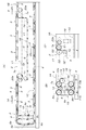
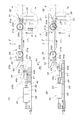
- FIG. 1A is a side view showing a main part of a transport apparatus adopting the configuration of an embodiment of the present invention
- FIG. 1B is a side view showing a drive system of its rising path part
- FIG. 1C is a terminal part of a storage path part
- FIG. 2 is an enlarged view of the rising path portion of FIG. 1A.
- FIG. 3 is a partial cross-sectional plan view showing the ascending path part to the start end part of the storage path part.
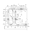
- FIG. 4 is a partially cutaway plan view showing the end of the storage path.
- FIG. 5A is a partially cutaway side view of the conveyance carriage in the drive path portion
- FIG. 5B is a plan view of the conveyance carriage.
- FIG. 6A is a longitudinal front view showing the transport carriage in the upper feed path section of the drive path section
- FIG. 6B is a longitudinal front view showing the transport carriage in the lower return path section of the drive path section
- FIG. 6C is a storage path section. It is a vertical front view which shows the conveyance trolley in.
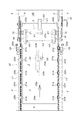
- 7A is a plan view of the auxiliary stopper
- FIG. 7B is a side view showing a non-operating state of the auxiliary stopper
- FIG. 7C is a side view showing an operating state of the auxiliary stopper
- 8A is a side view showing the non-operating state of the main stopper
- FIG. 8B is a partially cutaway side view showing the operating state of the auxiliary stopper
- FIG. 8C is a plan view of FIG.
- FIG. 9A is a plan view of the cart pushing means
- FIG. 9B is a side view of the cart pushing means.
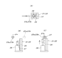
- FIG. 10A is a side view showing a first stage when the carriage is stopped and positioned at the final fixed position of the storage path portion
- FIG. 10B is a side view showing the second stage.
- FIG. 11A is a side view showing a first stage when the transport cart is sent out from the storage path section
- FIG. 11B is a side view showing the third stage.
- 1A is an upper drive path section
- 1B is a lower drive path section
- 2 is a storage path section.
- a carriage is provided by the upper drive path 1A, the storage path 2, and the lower drive path 1B that are horizontally disposed between the side drive path 1A and the lower drive path 1B.
- Three horizontal conveyance paths are configured.
- Reference numeral 1C denotes a return drive path section, which is connected to the lower side of the lower drive path section 1B and is horizontally disposed directly below the upper drive path section 1A and the storage path section 2.
- the return drive path portion 1C is connected to the starting end of the upper drive path portion 1A via the ascending path portion 1D.
- the upper drive path unit 1A and the lower drive path unit 1B are connected via a horizontal bypass path unit 1E that bypasses the storage path unit 2 directly below, but the upper drive path unit 1A and the lower drive path unit 1B are connected to each other.
- the drive path portion 1B may be configured independently and driven separately.
- a pair of left and right drive conveyor chains 4 as drive cables and a transport carriage 3 can travel.
- the pair of left and right drive conveyor chains 4 are constituted by a pair of left and right guide rails 5 to be supported.
- the ascending path section 1D includes a vertical path section 4a of a pair of left and right drive conveyor chains 4 extending from the guide wheel 7f at the end of the return drive path section 1C to the guide wheel 7a at the start end of the upper drive path section 1A, and guide wheels 7a, A pair of left and right drive conveyor chains 9 having the same structure as that of the drive conveyor chain 4 and stretched between the guide wheels 8a and 8b parallel to 7f, and a vertical path portion 9a far from the drive conveyor chain 4.
- the guide wheels 7a, 8a at the same height on the upper side are in the same direction by the spur gears 10a, 11a that rotate integrally with the guide wheels 7a, 8a and the intermediate spur gear 12 that meshes with these spur gears 10a, 11a.
- the guide wheels 7b and 8b that are interlocked and connected so as to rotate and at the same height on the lower side are spur gears 10b and 11b that rotate integrally with the guide wheels 7b and 8b, and these spur gears 10b and 11b.
- a machine-equipped motor 16 is provided.
- the pair of left and right drive conveyor chains 4 and 9 are respectively connected to the vertical path portions 4 a, 9a is configured to rotate together so as to move upward at the same speed.
- the pair of left and right drive conveyor chains 9 are provided with chain tension guide wheels 8 c for tensioning the drive conveyor chains 9 separately.
- the driving conveyor chain 4 driven as described above includes a guide wheel 7a at the start end and a guide wheel 7b at the end of the upper drive path 1A, a guide wheel 7c at the start of the horizontal bypass path 1E, and a guide wheel 7d at the end.
- the side drive path portion 1B is rotated horizontally, and thereafter, the return drive path portion 1C is rotated horizontally by being guided by a guide wheel (not shown) at the start end and a guide wheel 7f at the end of the return drive path portion 1C.
- the circulation path which moves and returns is rotated.
- the guide wheel 7c at the start of the horizontal bypass path 1E is a chain tension guide wheel that adjusts the tension of the drive conveyor chain 4 to be guided.
- the pair of left and right guide wheels 7e at the starting end of the lower drive path portion 1B includes a spur gear 51 that rotates coaxially with the guide wheels 7e, and the spur gears. 51 and a spur gear 53 that meshes with each other and rotates together with one transmission shaft 52 so as to rotate in conjunction with each other, and the pair of left and right drive conveyor chains 4 can be forcibly synchronized and rotated. It is configured as follows.
- the storage path section 2 includes a pair of left and right drive conveyor chains 17, a pair of left and right chain guide rails 18 that support and guide the drive conveyor chains 17 in the storage path section 2, and a motor with a speed reducer that rotationally drives the drive conveyor chain 17.
- the pair of left and right drive conveyor chains 17 is a pair of left and right guide wheels that are pivotally supported at a position that enters the start end side of the upper drive path portion 1A and the inner side of the guide wheel 7b at the end of the upper drive path portion 1A.
- the pair of left and right guide wheels 20b are interlocked and connected to each other by a transmission shaft 21, and a motor 19 with a speed reducer that rotationally drives the transmission shaft 21 is connected to one end of the transmission shaft 21.
- the pair of left and right guide wheels 20 a on the start end side of the storage path portion 2 are chain tension guide wheels that adjust the tension of the drive conveyor chain 17.
- the upper storage path portion 2 supported and guided by the chain guide rail 18 of the drive conveyor chain 17 includes a support level of the guide rail 5 installed on the upper drive path section 1A and the lower drive path section 1B,
- the upper surface of the drive conveyor chain 17 supported on the chain guide rail 18 (support level of the transport carriage 3) is configured to have the same height.
- the transport carriage 3 includes a pair of left and right wheels 21a and 21b having a flange on the inside at two front and rear positions. These wheels 21a and 21b are pivotally supported on the outer sides of the left and right side plates 3b that are bent downward from the left and right sides of the flat and rectangular base plate 3a, and all the wheels 21a and 21b include Driven pins 22a and 22b projecting concentrically outwardly are provided. Also, on the bottom surface side of the base plate 3a, a pair of front and rear rollers 23a, 23b are mounted on opposite sides of the left and right bearing plates 24a, 24b, which are fixedly projected downward at the center in the left-right width direction of the base plate 3a. It is supported.
- the pair of front and rear rollers 23 a and 23 b protrude from the front and rear outer sides of the pair of front and rear wheels 21 a and 21 b in a side view of the transport carriage 3, and from one virtual plane in contact with the outer periphery of the flange portion of the wheels 21 a and 21 b. Also, the rollers 23a and 23b are provided at a height that does not protrude downward, and the rollers 23a and 23b are positioned symmetrically outward with respect to the vertical center line of the transport carriage 3 in a front view of the transport carriage 3. Is shifted.
- a reinforcing plate 25 that reinforces the base plate 3a is fixed to the bottom surface side of the base plate 3a.
- the carriage propulsion claw portions 6 attached to the pair of left and right drive conveyor chains 4 are spaced at the same interval as the distance between the front and rear wheels 21a, 21b (driven pins 22a, 22b) in the conveyance carriage traveling direction.
- U attached to the inside of the pair of drive conveyor chains 4 and having a driven pin fitting recess that is oriented upward when the upper drive path 1A and the lower drive path 1B are rotated. It has a letter shape.
- the drive conveyor chain 9 stretched on the ascending path section 1D is the same as the drive conveyor chain 4 provided with the cart propulsion claw section 6, and this drive conveyor chain 9 is the drive conveyor.
- the cart propulsion claw portion 6 in the vertical path portion 9 a of the drive conveyor chain 9 is a laterally outward cart propulsion claw portion 6 in the vertical path portion 4 a of the drive conveyor chain 4.
- the ascending path portion 1 ⁇ / b> D includes the ascending path portion 1 ⁇ / b> D between the vertical path portion 4 a of the driving conveyor chain 4 and the vertical path portion 9 a of the driving conveyor chain 9.
- a guide plate 26 provided with a guide rail portion 26a that guides the outside of the wheel 21a of the transport carriage 3 that moves up in parallel while maintaining an upright posture, and a guide rail portion 26b that guides the inside of the wheel 21b of the transport carriage 3.
- a guide plate 27 having a guide rail portion 27a for guiding the outside of the wheel 21b of the transport carriage 3 is erected outside the vertical path portion 9a of the drive conveyor chain 9.
- the transport carriage 3 in the upright posture is provided with a pair of left and right guide rails via the wheels 21a and 21b. 5, and at this time, each of the driven pins 22 a and 22 b of the transport carriage 3 moves horizontally along the upper drive path 1 ⁇ / b> A and the lower drive path 1 ⁇ / b> B.
- the driven claw portion 6 is fitted in the driven pin fitting concave portion opened upward.
- the driven pins 22a and 22b of the carriage 3 are opened downwardly of the carriage propelling claw sections 6 of the pair of left and right drive conveyor chains 4 that move in an upside down posture along the return drive path section 1C. It will be fitted into the pin fitting recess. Accordingly, the pair of left and right drive conveyor chains 4 are rotationally driven in a predetermined direction by the motor 16 with a speed reducer, so that the conveying cart 3 in the upright posture can be moved to the upper drive path section 1A and the lower drive path section 1B. , The wheel 21a travels in the forward direction, and the return drive path section 1C can travel the conveying cart 3 in the upright posture in the reverse direction in which the wheels 21b precede. Note that, as shown in FIGS. 6A and 6B, a chain guide rail 28 that supports and guides the drive conveyor chain 4 is laid on the horizontal rotation path portion of the pair of left and right drive conveyor chains 4.
- the driven pin 22a of the rear wheel 21a receives thrust from the carriage propelling claw portion 6 of the drive conveyor chain 4
- the driven pin 22b of the front wheel 21b is the carriage of the drive conveyor chain 9.
- the horizontal and horizontal cart propulsion claw portions 6 in the vertical path portions 4a and 9a of 4 and 9 move upward in parallel while maintaining an upright posture.
- the presence of the guide rail portions 26a, 26b, 27a of the guide plates 26, 27 makes the parallel movement of the transport carriage 3 from the return drive path portion 1C to the ascending path portion 1D smoothly and reliably.
- the middle of the pair of left and right wheels 21a on the rear side is prevented.
- the transport carriage 3 When the transport carriage 3 reaches the upper end of the ascending path portion 1D, it becomes the front side, which is engaged with the cart propulsion claw portion 6 of the drive conveyor chain 4 that continuously moves from the ascending path portion 1D to the upper-side drive path portion 1A.
- the transport carriage 3 Through the driven pin 22a of the wheel 21a, the transport carriage 3 continuously receives thrust from the drive conveyor chain 4 and is drawn out to the upper drive path portion 1A.
- the cart propulsion claw portion 6 of the drive conveyor chain 9 fitted to the driven pin 22b of the wheel 21b on the rear side of the transport cart 3 rotates around the guide wheel 8a, and the driven pin Depart from 22b.
- the transport carriage 3 fed into the upper drive path portion 1A has a front wheel 21a from the time when the front wheel 21a reaches directly above the guide wheel 7a at the starting end of the upper drive path portion 1A.
- the wheel 21b on the rear side rolls on the upper horizontal guide rail portion 26c that follows the guide rail portion 26b of the guide plate 26. Since the rear wheel 21b becomes free between the upper horizontal guide rail portion 26c of the guide plate 26 and the guide rail 5, the rear side of the guide plate 26 that is separated from the upper horizontal guide rail portion 26c.
- the left and right side plates 3b of the transport carriage 3 (or the bottom of the transport carriage 3 are not shown).
- a supporting roller for supporting a reinforcing plate attached in the front-rear direction at an intermediate position in the left-right width direction is placed in the movement path of the transport carriage 3 that translates from the ascending path portion 1D to the upper-side drive path portion 1A. It can be pivotally supported in a position that does not enter.
- the transport carriage 3 sent to the upper drive path section 1A travels forward toward the storage path section 2 by a pair of left and right drive conveyor chains 4, and is sent out from the upper drive path section 1A to the storage path section 2.
- the driven pin 22a of the front wheel 21a is disengaged from the cart propulsion claw portion 6 of the drive conveyor chain 4 at the position of the guide wheel 7b at the end of the upper drive path portion 1A.
- the transport cart 3 is sent out from the upper drive path portion 1A to the storage path portion 2.
- the transport cart 3 sent to the storage path section 2 is a pair of left and right drive conveyors that move horizontally while the wheels 21 a and 21 b of the transport cart 3 are supported by the chain guide rails 18.
- the upper surface of the chain 17 is supported.
- the transport carriage 3 is supported by the guide rail 5 that supports and guides the wheels 21a and 21b in the upper drive path 1A, and is supported by the chain guide rail 18 through the drive conveyor chain 17 in the storage path 2.
- the guide rail 5 of the upper-side drive path portion 1A and the start end of the chain guide rail 18 of the storage path portion 2 due to the presence of the guide wheel 20a at the start end of the storage path portion 2, There arises an area where the transport carriage 3 cannot be supported by the guide rail.
- a support guide plate 29 having a length are constructed, and the front end portion or the rear end portion of the transport carriage 3 is temporarily supported by the support guide plate 29 via the rollers 23a and 23b. .
- a chain guide rail 30 for supporting and guiding the drive conveyor chain 17 is also laid on the return path portion of the drive conveyor chain 17 below the storage path unit 2.
- an auxiliary stopper 31, a main stopper 32, a subsequent carriage temporary stop stopper 33, a carriage pushing means 34, and a support guide plate 35 are disposed at the end of the storage path section 2.
- the auxiliary stopper 31 and the succeeding carriage temporary stop stopper 33 have the same structure, and as shown in FIG. 7, an elevating body 37 supported by an elevating guide rail 36 so as to be movable up and down, and driving the elevating body 37 up and down.
- the auxiliary stopper 31 is configured such that the driven pins 22a of the pair of left and right wheels 21a on the front side of the transport carriage 3 propelled in the forward direction by the drive conveyor chain 17 in the storage path section 2 are the guide wheels at the start of the lower side drive path section 1B.
- the front roller 23a of the transport cart 3 is received by the stopper 37a. It is arranged at a position where As shown in FIG.
- the stopper 33 for the subsequent carriage temporary stop having the same structure is disposed at the rear end of the leading carriage 3 (stopped from the base plate 3a) stopped at a fixed position by the auxiliary stopper 31 via the front roller 23a.
- the main stopper 32 includes a pair of left and right vertical movement hooks 39 that are detachable with respect to the driven pins 22b of the pair of left and right wheels 21b on the rear side of the leading transport carriage 3 stopped at a fixed position by the auxiliary stopper 31.
- This is composed of a pair of left and right cylinder units 40 that vertically drive each vertical movement hook 39 individually.
- the pair of left and right vertical movement hooks 39 is attached to the inner end of a horizontal support shaft 42 supported horizontally by a bearing member 41 and has a rear end portion extending forward, and the cylinder unit 40 includes the rotation support shaft.
- An operation lever 43 attached to the outer end of 42 and extending forward is driven up and down, and the cylinder unit 40 is extended so that the vertical movement hook 39 is moved up via the operation lever 43 and the rotation support shaft 42.
- the vertical movement hook 39 is retracted to the upper side of the movement path of each driven pin 22a, 22b accompanying the forward movement of the transport carriage 3, and conversely, the cylinder unit 40 is contracted and operated.
- the vertical movement hook 39 is moved downward via the lever 43 and the rotation support shaft 42, the vertical movement hook 39 has a hook portion at the tip of each of the driven pins 22a, 22. Enters into the moving path, it can be switched to stop working attitude.
- the carriage pushing means 34 is arranged in parallel with the subsequent carriage temporary stop stopper 33, and as shown in FIG. 9, is constituted by a pusher 44 and a driving means 45 for moving the pusher 44 forward and backward.
- the pusher 44 is supported on a movable base 47 supported on a slide rail 46 laid in the front-rear horizontal direction so as to be movable forward and backward, and is pivotally supported around a support shaft 44 a in the horizontal direction.
- a stopper member 44b for receiving the rear end portion of the pusher 44 when the pusher 44 is in a post-pushing action posture standing obliquely forward and upward from the support shaft 44a is attached to the movable base 47.
- a front end portion of the weight block 44c is fixed to the side surface of the rear end portion of the pusher 44 in order to urge the pusher operation posture.
- the cart pushing means 34 is a roller on the rear side of the leading transport cart 3 that is stopped at a fixed position by the auxiliary stopper 31 when the movable table 47 (pusher 44) is in the retreat limit position.
- a pusher 44 that is biased and held in the pushing action posture slightly behind 23b is disposed at a position where the pusher 44 enters the movement path of the rear roller 23b as the transport carriage 3 moves forward.
- the pusher 44 biased and held in the post-pressing action posture is pushed forward by the roller 23b on the rear side of the transport carriage 3 moving forward, thereby causing a weight block 44c as shown by an imaginary line in FIG. 9B.
- the drive means 45 includes a first cylinder unit 48 that moves the movable base 47 (pusher 44) forward from the backward limit position P0 to the first forward limit position P1, and the movable base 47 (pusher 44) at the first forward limit position P1. Cylinder unit 48, 49 projecting from both ends is connected and integrated so that each piston rod extends in a direction opposite to each other.
- One of the piston rods is pivotally supported on a base 50 on which a slide rail 46 is laid, and the other piston rod is pivotally connected to the movable base 47.
- the transport carriage 3 sent from the upper drive path 1A to the storage path 2 by the drive conveyor chain 4 is placed on the pair of left and right drive conveyor chains 17 constituting the storage path 2.
- the drive conveyor chain 17 With the wheels 21a and 21b being supported, the drive conveyor chain 17 is moved forward along the storage path section 2 as the drive conveyor chain 17 rotates.
- the auxiliary stopper 31 at the end of the storage path portion 2 is switched by the cylinder unit 38 to the upper limit position where the stopper portion 37a can receive the roller 23a on the front side of the transport carriage 3.
- the main stopper 32 on the front side is switched by the cylinder unit 40 to a non-acting posture in which the pair of left and right vertical movement hooks 39 are in the upper movement limit.
- the cart pushing means 34 is in a state in which the pusher 44 biased and held in the pushing action posture stands by at the retreat limit position by the movable stand 47.
- the subsequent carriage temporary stop stopper 33 is switched to a non-operating state in which the stopper portion 37 a has retracted downward from the moving path of the roller 23 a on the front side of the transport carriage 3.
- the transport carriage 3 that moves forward in the storage path section 2 toward the end by the drive conveyor chain 17 has the front roller 23a passed over the stopper 33 for the subsequent carriage temporary stop, and the pair of front left and right wheels.
- the driven pin 22a of 21a passes below the pair of left and right vertical movement hooks 39 in the non-acting posture of the upper limit of the main stopper 32, and the rear roller 23b is at the backward limit position of the cart pushing means 34. 4 and 10A, the roller 23a on the front side is received by the stopper portion 37a of the elevating body 37 at the upper limit of movement of the auxiliary stopper 31 after passing through a certain pusher 44 while being pushed forward.
- the storage path unit 2 stops at the terminal fixed position.
- the pusher 44 of the cart pushing means 34 is moved forward by the stroke S1 by moving the first cylinder unit 48 of the driving means 45 through the movable stand 47, and the reverse limit position is reached.
- the pusher 44 that has reached the first forward limit position P1 is connected to the leading transport carriage 3 that is prevented from moving forward from the final fixed position of the storage path portion 2 by a pair of left and right vertical movement hooks 39 of the main stopper 32. The backward movement is prevented via the rear roller 23b.
- the transport carriage 3 is sandwiched from the front and rear by the pair of left and right vertical movement hooks 39 of the main stopper 32 and the pusher 44 of the carriage pusher 34 at the final fixed position of the storage path section 2 to move the transport carriage 3 back and forth. Positioning will be impossible.
- the drive conveyor chain 17 of the storage path 2 is continuously driven and moved forward on the chain guide rail 18, but the advance is stopped by the auxiliary stopper 31 and the main stopper 32 as described above.
- the drive conveyor chain 17 passes through the transport carriage 3 while rotating the wheels 21a and 21b of the transport carriage 3 in the reverse direction.
- each transport carriage 3 following the leading transport carriage 3 stopped at the final fixed position of the storage path section 2 has its front end (front end of the base plate 3a) at the rear end of the transport carriage 3 stopped immediately before ( It stops at a position where it abuts against the rear end of the base plate 3a, and only the drive conveyor chain 17 continues to move forward.
- the second cylinder unit 49 in the driving means 45 of the cart pushing means 34 is extended so that the first forward limit position P Is moved forward by a stroke S2 is the pusher 44 together with the movable base 47 in the switch to the second forward limit position P2.
- the leading stop conveyance carriage 3 is moved forward by the stroke S2 by the pusher 44 of the carriage pushing means 34 via the roller 23b on the rear side, so that the lower stop side from the fixed position X around the guide wheel 7e.
- the driven pins 22a of the pair of left and right wheels 21a on the front side of the leading stop conveyance carriage 3 are forcibly pushed into the carriage propelling claw section 6 of the drive conveyor chain 4 moving forward into the drive path section 1B.
- the leading stop conveying carriage 3 receives thrust from the carriage propelling claw portion 6 of the drive conveyor chain 4 via the pair of left and right driven pins 22a, and the leading stop conveying carriage 3 is It is drawn into the lower side drive path portion 1B.
- the leading transport carriage 3 once stopped at the end of the storage path unit 2 is sent to the lower drive path unit 1B at a predetermined timing to be stopped at the start end of the lower drive path unit 1B. Instead, it can be continuously driven by the cart propulsion claw 6 of the drive conveyor chain 4 of the lower drive path 1B and smoothly moved forward on the guide rail 5 of the lower drive path 1B. Accordingly, by appropriately changing the timing at which the leading transport carriage 3 once stopped at the end of the storage path section 2 is sent to the lower drive path section 1B, the interval between the transport carts 3 that move forward in the storage path section 2 is changed. Can be changed arbitrarily.
- the carriage positioning means for positioning the transport carriage 3 at the final fixed position of the storage path portion 2 so as not to move back and forth is a releasable carriage positioning means.
- the main stopper 32, the pusher 44 of the carriage pushing means 34, and the pusher 44 Is configured by the first cylinder unit 48 that switches from the backward limit position P0 to the first forward limit position P1, but a dedicated pusher different from the pusher 44 of the cart pushing means 34 may be provided.
- the auxiliary stopper 31 and the main stopper 32 are provided as stoppers for receiving the transport carriage 3 at the final fixed position of the storage path portion 2, the present invention can be implemented using only one of the stoppers.
- rollers 23 a provided at two positions on the front and rear of the bottom of the transport carriage 3 as pushers for sandwiching and positioning the transport carriage 3 with a stopper that receives the transport carriage 3 at the final fixed position of the storage path section 2.
- the pusher that presses the roller 23b on the rear side among the front ends 23b is used, the pressing target portion on the transport carriage 3 side of the pusher may be any portion.
- the transportation device using the carriage of the present invention temporarily stops the transportation carriage in the middle of the transportation path for transporting the object to be transported while being supported on the transportation carriage, and sends the transportation object to the lower transportation path. It can be used as a transport device provided with a storage path for changing the timing.
Landscapes
- Engineering & Computer Science (AREA)
- Mechanical Engineering (AREA)
- Transportation (AREA)
- Intermediate Stations On Conveyors (AREA)
- Pusher Or Impeller Conveyors (AREA)
Abstract
La présente invention concerne un dispositif de transport qui utilise un chariot et dans lequel : une partie d'itinéraire d'entraînement (1B), qui amène un chariot de transport (3) à être entraîné par force pour se déplacer à des intervalles prédéterminés, est reliée à une partie d'itinéraire de stockage (2) constituée par une chaîne transporteuse d'entraînement (17) qui porte le chariot de transport (3) de telle sorte que le chariot de transport (3) peut se déplacer librement ; la partie d'itinéraire d'entraînement (1B) est pourvue d'une chaîne transporteuse d'entraînement (4) comprenant des parties de griffe de propulsion de chariot (6), sur chacune desquelles une broche déplacée (22a), qui est disposée sur le chariot de transport (3) et qui s'étend horizontalement dans la direction gauche/droite, doit être ajustée de manière à être librement détachée/réajustée dans la direction haut/bas, avec des espaces interposés entre les parties de griffe de propulsion de chariot respectives (6). Le dispositif de transport est pourvu : de moyens de positionnement de chariot (32, 44) qui positionnent le chariot de transport (3) de telle sorte que celui-ci (3) est dans un état incapable de se déplacer vers l'avant/vers l'arrière, dans une position fixe dans laquelle la broche mobile (22a) est positionnée immédiatement devant un anneau de guidage (7e) pour une partie correspondante des parties de griffe de propulsion de chariot (6) ; d'un moyen de poussée de chariot qui pousse le chariot de transport (3) positionné dans la position fixe, à un moment où la broche déplacée (22a) est ajustée sur la partie de griffe de propulsion de chariot (6).
Priority Applications (1)
| Application Number | Priority Date | Filing Date | Title |
|---|---|---|---|
| US16/146,299 US10556747B2 (en) | 2016-03-31 | 2018-09-28 | Conveyance device using carriage |
Applications Claiming Priority (2)
| Application Number | Priority Date | Filing Date | Title |
|---|---|---|---|
| JP2016-070921 | 2016-03-31 | ||
| JP2016070921A JP6478059B2 (ja) | 2016-03-31 | 2016-03-31 | 台車利用の搬送装置 |
Related Child Applications (1)
| Application Number | Title | Priority Date | Filing Date |
|---|---|---|---|
| US16/146,299 Continuation US10556747B2 (en) | 2016-03-31 | 2018-09-28 | Conveyance device using carriage |
Publications (1)
| Publication Number | Publication Date |
|---|---|
| WO2017169256A1 true WO2017169256A1 (fr) | 2017-10-05 |
Family
ID=59964096
Family Applications (1)
| Application Number | Title | Priority Date | Filing Date |
|---|---|---|---|
| PCT/JP2017/005826 Ceased WO2017169256A1 (fr) | 2016-03-31 | 2017-02-17 | Dispositif de transport utilisant un chariot |
Country Status (4)
| Country | Link |
|---|---|
| US (1) | US10556747B2 (fr) |
| JP (1) | JP6478059B2 (fr) |
| TW (1) | TW201741215A (fr) |
| WO (1) | WO2017169256A1 (fr) |
Families Citing this family (5)
| Publication number | Priority date | Publication date | Assignee | Title |
|---|---|---|---|---|
| JP7164444B2 (ja) * | 2019-01-10 | 2022-11-01 | シャープ株式会社 | 走行装置及び台車 |
| CN111098439B (zh) * | 2019-12-25 | 2023-04-21 | 张家港力勤机械有限公司 | 一种发泡基材的预热输送装置 |
| EP4140919A1 (fr) * | 2021-08-24 | 2023-03-01 | Concept & Forme Developpements SA | Convoyeur permutateur de palettes |
| CN118850753B (zh) * | 2024-09-29 | 2025-01-10 | 山东康友光电科技股份有限公司 | 应用于玻璃生产的柔性输送系统 |
| CN120421384B (zh) * | 2025-07-07 | 2026-01-23 | 成都工业职业技术学院 | 一种钢结构加工用弯折装置 |
Citations (6)
| Publication number | Priority date | Publication date | Assignee | Title |
|---|---|---|---|---|
| US2512356A (en) * | 1947-09-03 | 1950-06-20 | Charles Gottfried | Conveyer system for oven trays and the like |
| JPS5942753U (ja) * | 1982-09-13 | 1984-03-21 | 株式会社椿本チエイン | 複動式トロリ−コンベヤにトロリ−を送り込むフイ−ダ |
| JPS61252031A (ja) * | 1985-04-30 | 1986-11-10 | Nec Home Electronics Ltd | 移送装置 |
| JPH0985336A (ja) * | 1995-09-19 | 1997-03-31 | Kawasaki Steel Corp | 金属帯コイル搬送用台車式チェーンコンベヤ |
| JP2011079624A (ja) * | 2009-10-06 | 2011-04-21 | Ishihara Giken:Kk | パレット作業台循環搬送装置 |
| JP2014005114A (ja) * | 2012-06-25 | 2014-01-16 | Daifuku Co Ltd | 搬送装置 |
Family Cites Families (4)
| Publication number | Priority date | Publication date | Assignee | Title |
|---|---|---|---|---|
| US3850106A (en) * | 1973-11-30 | 1974-11-26 | Rexnord Inc | Elevator apparatus |
| JP6128326B2 (ja) * | 2013-10-08 | 2017-05-17 | 株式会社ダイフク | スラットコンベヤ |
| JP6241750B2 (ja) * | 2014-11-11 | 2017-12-06 | 株式会社ダイフク | 台車式搬送装置 |
| JP6332753B2 (ja) * | 2014-11-11 | 2018-05-30 | 株式会社ダイフク | 台車式搬送装置 |
-
2016
- 2016-03-31 JP JP2016070921A patent/JP6478059B2/ja active Active
-
2017
- 2017-02-07 TW TW106103918A patent/TW201741215A/zh unknown
- 2017-02-17 WO PCT/JP2017/005826 patent/WO2017169256A1/fr not_active Ceased
-
2018
- 2018-09-28 US US16/146,299 patent/US10556747B2/en not_active Expired - Fee Related
Patent Citations (6)
| Publication number | Priority date | Publication date | Assignee | Title |
|---|---|---|---|---|
| US2512356A (en) * | 1947-09-03 | 1950-06-20 | Charles Gottfried | Conveyer system for oven trays and the like |
| JPS5942753U (ja) * | 1982-09-13 | 1984-03-21 | 株式会社椿本チエイン | 複動式トロリ−コンベヤにトロリ−を送り込むフイ−ダ |
| JPS61252031A (ja) * | 1985-04-30 | 1986-11-10 | Nec Home Electronics Ltd | 移送装置 |
| JPH0985336A (ja) * | 1995-09-19 | 1997-03-31 | Kawasaki Steel Corp | 金属帯コイル搬送用台車式チェーンコンベヤ |
| JP2011079624A (ja) * | 2009-10-06 | 2011-04-21 | Ishihara Giken:Kk | パレット作業台循環搬送装置 |
| JP2014005114A (ja) * | 2012-06-25 | 2014-01-16 | Daifuku Co Ltd | 搬送装置 |
Also Published As
| Publication number | Publication date |
|---|---|
| JP2017178593A (ja) | 2017-10-05 |
| JP6478059B2 (ja) | 2019-03-06 |
| US10556747B2 (en) | 2020-02-11 |
| TW201741215A (zh) | 2017-12-01 |
| US20190031444A1 (en) | 2019-01-31 |
Similar Documents
| Publication | Publication Date | Title |
|---|---|---|
| JP6478059B2 (ja) | 台車利用の搬送装置 | |
| US8459438B2 (en) | Workpiece conveyance device | |
| JP6501078B2 (ja) | 搬送用走行体利用の搬送設備 | |
| JPS6154690B2 (fr) | ||
| CN103303668A (zh) | 用于在相邻的模块之间转移物品层的方法和装置 | |
| KR20100126495A (ko) | 컨베이어 상으로의 차량 이재 장치 | |
| WO2006016502A1 (fr) | Appareil de transport avec table élévatrice de support pour l’objet transporté | |
| JP5698116B2 (ja) | 搬送装置 | |
| JP5835556B2 (ja) | 移載装置及び移載方法 | |
| CN107000942A (zh) | 台车式输送装置 | |
| JP2008238914A (ja) | 台車式搬送設備 | |
| CN110127567B (zh) | 搬运作业设备 | |
| JP4120626B2 (ja) | 搬送装置 | |
| JP5839285B2 (ja) | 搬送装置 | |
| JP2008184268A (ja) | 昇降移載装置 | |
| JP2007302242A (ja) | 台車式搬送装置 | |
| JP5601531B2 (ja) | 物品搬送装置 | |
| JPH03249022A (ja) | 荷積み方法 | |
| JP6218044B2 (ja) | 台車式搬送装置 | |
| JP2006264845A (ja) | リフト装置 | |
| JP6065287B2 (ja) | 搬送台車昇降装置 | |
| JP3731519B2 (ja) | 自動倉庫 | |
| US3550747A (en) | Trans-lift section conveyor | |
| JP4065633B2 (ja) | 機械式駐車装置 | |
| JP5598709B2 (ja) | 物品移載設備 |
Legal Events
| Date | Code | Title | Description |
|---|---|---|---|
| NENP | Non-entry into the national phase |
Ref country code: DE |
|
| 121 | Ep: the epo has been informed by wipo that ep was designated in this application |
Ref document number: 17773804 Country of ref document: EP Kind code of ref document: A1 |
|
| 122 | Ep: pct application non-entry in european phase |
Ref document number: 17773804 Country of ref document: EP Kind code of ref document: A1 |