WO2017169295A1 - Amortisseur et dispositif anti-chute pourvu dudit amortisseur - Google Patents
Amortisseur et dispositif anti-chute pourvu dudit amortisseur Download PDFInfo
- Publication number
- WO2017169295A1 WO2017169295A1 PCT/JP2017/006290 JP2017006290W WO2017169295A1 WO 2017169295 A1 WO2017169295 A1 WO 2017169295A1 JP 2017006290 W JP2017006290 W JP 2017006290W WO 2017169295 A1 WO2017169295 A1 WO 2017169295A1
- Authority
- WO
- WIPO (PCT)
- Prior art keywords
- cylinder
- chamber
- damper
- cylinder part
- cylinder portion
- Prior art date
- Legal status (The legal status is an assumption and is not a legal conclusion. Google has not performed a legal analysis and makes no representation as to the accuracy of the status listed.)
- Ceased
Links
Images


Classifications
-
- A—HUMAN NECESSITIES
- A47—FURNITURE; DOMESTIC ARTICLES OR APPLIANCES; COFFEE MILLS; SPICE MILLS; SUCTION CLEANERS IN GENERAL
- A47B—TABLES; DESKS; OFFICE FURNITURE; CABINETS; DRAWERS; GENERAL DETAILS OF FURNITURE
- A47B97/00—Furniture or accessories for furniture, not provided for in other groups of this subclass
-
- F—MECHANICAL ENGINEERING; LIGHTING; HEATING; WEAPONS; BLASTING
- F16—ENGINEERING ELEMENTS AND UNITS; GENERAL MEASURES FOR PRODUCING AND MAINTAINING EFFECTIVE FUNCTIONING OF MACHINES OR INSTALLATIONS; THERMAL INSULATION IN GENERAL
- F16F—SPRINGS; SHOCK-ABSORBERS; MEANS FOR DAMPING VIBRATION
- F16F9/00—Springs, vibration-dampers, shock-absorbers, or similarly-constructed movement-dampers using a fluid or the equivalent as damping medium
- F16F9/06—Springs, vibration-dampers, shock-absorbers, or similarly-constructed movement-dampers using a fluid or the equivalent as damping medium using both gas and liquid
-
- F—MECHANICAL ENGINEERING; LIGHTING; HEATING; WEAPONS; BLASTING
- F16—ENGINEERING ELEMENTS AND UNITS; GENERAL MEASURES FOR PRODUCING AND MAINTAINING EFFECTIVE FUNCTIONING OF MACHINES OR INSTALLATIONS; THERMAL INSULATION IN GENERAL
- F16F—SPRINGS; SHOCK-ABSORBERS; MEANS FOR DAMPING VIBRATION
- F16F9/00—Springs, vibration-dampers, shock-absorbers, or similarly-constructed movement-dampers using a fluid or the equivalent as damping medium
- F16F9/32—Details
Definitions
- the present invention relates to a damper and a fall prevention device including the damper.
- Patent Document 1 discloses a fall prevention device equipped with a conventional damper.
- the damper includes a cylinder, a rod guide, a piston, and a rod.
- the cylinder has a bottomed cylindrical shape.
- the rod guide seals the opening of the cylinder.
- the piston is slidably accommodated in the cylinder.
- the rod has a proximal end connected to the piston, slidably inserted through the rod guide, and a distal end protruding outside the cylinder.
- the damper also encloses hydraulic oil and compressed gas in the cylinder. This damper comprises the fall prevention apparatus attached between the upper surface of furniture, and a ceiling.
- This overturn prevention device is configured such that the bottom of the cylinder of the damper is positioned below the opening, the rod projects upward from the cylinder, and the center axis of the cylinder and the rod is inclined at a predetermined angle with respect to the horizontal plane. It is attached between the upper surface and the ceiling.
- this fall prevention device when the furniture is tilted due to shaking such as an earthquake, the damping force generated by the movement of the piston of the damper in the hydraulic oil acts on the furniture to suppress the tilt of the furniture, and the furniture falls Can be prevented.
- the piston of this damper can move not only in the hydraulic oil but also in the compressed gas sealed above the hydraulic oil.
- the damper cannot generate a damping force even if the piston moves in the compressed gas. That is, this damper cannot generate a damping force over the entire stroke range.
- the fall prevention device provided with this damper is arranged in a state where the piston is disposed in the compressed gas sealed above the hydraulic oil, and the upper surface and the ceiling of the furniture. There is a risk of being attached between.
- the anti-tip device is installed with the piston placed in compressed gas, when the furniture is tilted due to shaking such as an earthquake, the damper will contract until the piston moves into the hydraulic fluid. Does not occur. For this reason, this fall prevention device may cause the furniture to fall without the damping force of the damper acting effectively on the furniture.
- the present invention has been made in view of the above-described conventional situation, and provides a damper that generates a damping force in the entire stroke range, and by providing the damper, it is possible to satisfactorily prevent an article from falling over. Providing a fall prevention device that can be used is a problem to be solved.
- the damper of the first invention includes a first cylinder part, a second cylinder part, a partition member, a rod guide, a first piston, a rod, and a second piston.
- the first cylinder part is cylindrical. One end of the second cylinder portion communicates with the first cylinder portion.
- the second cylinder part has a cylindrical shape with the other end closed.
- the partition member is provided at a boundary portion between the first cylinder portion and the second cylinder portion. Further, the partition member has a communication path that communicates the first cylinder part and the second cylinder part.
- the rod guide seals the opening that opens at the end of the first cylinder.
- the first piston is slidably accommodated in the first cylinder portion filled with the working liquid.
- first piston partitions the inside of the first cylinder portion into a first chamber and a second chamber.
- the rod has a proximal end connected to the first piston. Further, the rod is slidably inserted through the rod guide, and the tip side protrudes outside the first cylinder portion.
- the second piston is slidably accommodated in the second cylinder part. The second piston communicates with the second chamber and divides the inside of the second cylinder portion into a third chamber filled with the working liquid and a fourth chamber filled with gas.
- the damper of the second invention includes a first cylinder part, a second cylinder part, a partition member, a rod guide, a first piston, a rod, and a bag.
- the first cylinder part is cylindrical.
- One end of the second cylinder portion communicates with the first cylinder portion.
- the second cylinder part has a cylindrical shape with the other end closed.
- the partition member is provided at a boundary portion between the first cylinder portion and the second cylinder portion. Further, the partition member has a communication path that communicates the first cylinder part and the second cylinder part.
- the rod guide seals the opening that opens at the end of the first cylinder.
- the first piston is slidably accommodated in the first cylinder portion filled with the working liquid.
- first piston partitions the inside of the first cylinder portion into a first chamber and a second chamber.
- the rod has a proximal end connected to the first piston. Further, the rod is slidably inserted through the rod guide, and the tip side protrudes outside the first cylinder portion.
- the bag body is accommodated in the second cylinder part. Further, the bag body is filled with gas.
- the damper of the present invention may include a communication portion that communicates the first cylinder portion and the second cylinder portion so that the first cylinder portion and the second cylinder portion are arranged in parallel.
- the communication path of the partition member includes a first communication path that provides resistance to the working fluid that flows between the first cylinder part and the second cylinder part, and from the second cylinder part to the first cylinder part. And a second communication passage provided with a check valve that allows only the flow of the working fluid.
- the first piston allows the working fluid flowing between the first chamber and the second chamber to resist, and the reverse allows only the working fluid flow from the first chamber to the second chamber.
- a fourth communication passage provided with a stop valve.
- the fall prevention device of the present invention includes the damper.
- the rod protrudes upward from the first cylinder, and the center axis of the first cylinder and the rod is inclined at a predetermined angle with respect to the horizontal plane between the upper surface of the article installed on the installation surface and the ceiling. It is attached.
- the predetermined angle is 65 ° to 75 °, which can prevent the article from falling down.
- articles may fall down due to earthquakes, such as furniture, a bed with multiple beds connected vertically, a large TV, a refrigerator, a bookcase, a showcase, a server rack, etc. Some of them are included.
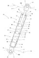
- FIG. 1 It is a side view which shows the state which attached the fall prevention apparatus of Embodiment 1 between the upper surface of furniture, and the ceiling. It is sectional drawing which shows the fall prevention apparatus of Embodiment 1.
- FIG. 2 It is sectional drawing which shows the fall prevention apparatus of Embodiment 2.
- FIG. It is sectional drawing which shows the fall prevention apparatus of Embodiment 3.
- Embodiments 1 to 4 embodying a fall prevention device including a damper according to the present invention will be described with reference to the drawings.
- the overturn prevention device of Embodiment 1 includes a damper 10 and a pair of base portions 1 ⁇ / b> A and 1 ⁇ / b> B. At least one or more fall prevention devices are attached between the upper surface of the furniture F and the ceiling T.
- the furniture F is installed on the floor surface with the back surface facing a wall surface W extending vertically from a floor surface (not shown).
- the furniture F has a rectangular parallelepiped shape, and has a door, a drawer, etc. (not shown) on the front (right side in FIG. 1), and can store clothes, accessories, and the like inside.
- the furniture F has a rectangular shape in which the horizontal cross-sectional shape is long in the left-right direction (the depth direction in FIG. 1).
- the furniture F may be tilted forward (rightward in FIG. 1) due to shaking such as an earthquake.
- the damper 10 is provided with a first cylinder part 20, a second cylinder part 30, a partition member 40, a rod guide 50, a first piston 60, a rod 70, a second piston 80, and both ends.
- Two joint portions 90A and 90B are provided.
- the first cylinder part 20 and the second cylinder part 30 are formed by a cylindrical cylinder member 21 having one end opened and the other end closed.
- the cylinder member 21 has a partition member 40 attached to an intermediate portion in the axial direction.
- the cylinder member 21 forms the first cylinder part 20 on one end side where the cylinder member 21 is opened with the partition member 40 as a boundary, and forms the second cylinder part 30 on the other end part side which is closed. That is, the 1st cylinder part 20 is cylindrical.
- the second cylinder portion 30 has a cylindrical shape in which one end portion is continuous with the first cylinder portion 20 and the other end portion is closed.
- the first cylinder part 20 is filled with hydraulic oil Y.
- the partition member 40 is provided at the boundary between the first cylinder part 20 and the second cylinder part 30 as described above.
- the partition member 40 has a disk shape.
- the partition member 40 has an outer diameter substantially equal to the inner diameter of the cylinder member 21 (the first cylinder portion 20 and the second cylinder portion 30).
- the partition member 40 is formed with a recess 41 that is recessed in the central axis direction so as to go around the outer peripheral surface.
- the cylinder member 21 is formed with a constricted portion 23 that is recessed inward so as to go around the peripheral wall portion of the portion where the partition member 40 is provided.
- the partition member 40 is fixed by fitting the throttle portion 23 of the cylinder member 21 into a recess 41 formed on the outer peripheral surface.
- the partition member 40 has a first communication passage 43 that communicates the first cylinder portion 20 and the second cylinder portion 30.
- the first communication passage 43 imparts resistance to the hydraulic oil Y flowing between the first cylinder part 20 and the second cylinder part 30.
- the partition member 40 has a second communication passage 45 that communicates the first cylinder portion 20 and the second cylinder portion 30.
- the second communication passage 45 is provided with a check valve 47 that allows only the flow of the hydraulic oil Y from the second cylinder part 30 to the first cylinder part 20 accompanying the extension operation of the damper 10. For this reason, the damper 10 also generates a greater damping force during the contraction operation than during the extension operation, even by the partition member 40.
- the rod guide 50 seals the opening 25 opened at one end of the first cylinder portion 20.
- the rod guide 50 is annular.
- the rod guide 50 has an outer diameter substantially equal to the inner diameter of the opening 25 of the first cylinder portion 20.
- the inner diameter of the through hole 51 penetrating in the center is slightly larger than the outer diameter of the rod 70, and the rod 70 is slidably inserted.
- the rod guide 50 is provided with a groove portion that goes around the inner peripheral surface of the through hole 51.
- an annular oil seal 53 is fitted in a groove provided on the inner peripheral surface of the through hole 51.
- the damper 10 is filled with the hydraulic oil Y in the first cylinder portion 20 and seals between the rod guide 50 and the rod 70 by the oil seal 53.
- the friction with the rod 70 is suppressed, the slidability is good, and the response with a small amplitude is good.
- the first piston 60 has a disk shape.
- the outer diameter of the first piston 60 is slightly smaller than the inner diameter of the first cylinder part 20.
- the first piston 60 is slidably accommodated in the first cylinder part 20 filled with hydraulic oil Y.
- the first piston 60 partitions the first cylinder portion 20 into a first chamber C1 and a second chamber C2.
- the first piston 60 has a third communication passage 61 that communicates the first chamber C1 and the second chamber C2.
- the third communication passage 61 provides resistance to the hydraulic oil Y flowing between the first chamber C1 and the second chamber C2.
- the first piston 60 has a fourth communication passage 63 that communicates the first chamber C1 and the second chamber C2.
- the fourth communication path 63 is provided with a check valve 65 that allows only the flow of the hydraulic oil Y from the first chamber C1 to the second chamber C2 due to the extension operation of the damper 10. For this reason, the damper 10 generates a greater damping force during the contraction operation than during the extension operation.
- the damper 10 is a pressure damper in which the first piston 60 and the partition member 40 generate a greater damping force during the contraction operation than during the extension operation.
- the rod 70 is cylindrical.
- the rod 70 is connected to the first piston 60 at the base end. Further, as described above, the rod 70 is slidably inserted through the through hole 51 of the rod guide 50. The rod 70 protrudes to the outside of the first cylinder portion 20 at the tip side.
- the second piston 80 has a disk shape.
- the second piston 80 partitions the second cylinder part 30 into a third chamber C3 and a fourth chamber C4.
- the third chamber C3 communicates with the second chamber C2 and is filled with hydraulic oil Y.
- the fourth chamber C4 is filled with the gas G.
- the second piston 80 is formed with a groove that goes around the outer peripheral surface.
- the second piston 80 has an annular packing 81 that fits into the groove. For this reason, in the second cylinder part 30, the hydraulic oil Y filled in the third chamber C3 flows into the fourth chamber C4, or the gas G filled in the fourth chamber C4 enters the third chamber C3. Inflow is prevented.
- Each joint part 90A, 90B is formed by bending a flat metal fitting.
- Each joint portion 90 ⁇ / b> A, 90 ⁇ / b> B is connected to the other end portion of the cylinder member 21 closed and the tip portion of the rod 70.
- Each joint portion 90 ⁇ / b> A, 90 ⁇ / b> B is formed with a through hole 91 that penetrates in a direction orthogonal to the axis of the damper 10.
- the pair of base portions 1 ⁇ / b> A and 1 ⁇ / b> B is a first base portion 1 ⁇ / b> A connected to a joint portion 90 ⁇ / b> A connected to the other end portion of the cylinder member 21, and is connected to a joint portion 90 ⁇ / b> B connected to the distal end portion of the rod 70. 2 base portion 1B.
- the first base portion 1A is placed in contact with the upper surface of the furniture F, and the second base portion 1B is in contact with the ceiling T.
- the first base portion 1A and the second base portion 1B have the same form and structure.
- Each base portion 1A, 1B has a base portion main body 3, a rotating shaft member 5, and a non-slip portion 7.
- the base portion main body 3 has a rectangular outer shape (hereinafter, the base portion main body 3 in the plan view).
- the direction in which the long side extends in the outer shape is referred to as “long side direction”, and the direction in which the short side extends is referred to as “short side direction”.
- the lower end edge of the base body 3 is linearly parallel to the upper surface of the furniture F.
- the upper end edge has an arcuate outer shape that swells upward from both sides of the lower end edge (see FIG. 1).
- the base portion main body 3 has depressions 9 formed on both sides of the central portion in the long side direction.
- the recess 9 is open outward in the upward direction and the short side direction.
- the hollow portion 9 has an insertion hole penetrating in the short side direction opened on a side surface.
- the rotation shaft member 5 is inserted from one of the insertion holes of the base portion main body 3, and the central axis becomes the rotation shaft of the damper 10 in each of the base portions 1A and 1B.
- the non-slip portion 7 has a similar (rectangular) outer shape that is slightly larger than the outer shape of the base body 3.
- the anti-slip part 7 is an elastic body.
- skid part 7 is fitted by the lower end opening of the base part main body 3 in the 1st base part 1A in the state mounted in contact with the upper surface of the furniture F.
- skid part 7 is a substantially flat plate.
- the anti-slip portion 7 has a flat upper surface or a surface that contacts the ceiling T of the furniture F.
- the anti-slip portion 7 is detachably attached to the base portion main body 3 by its elastic force.
- the rod 70 protrudes upward from the cylinder member 21 (first cylinder portion 20), and the cylinder member 21 (first cylinder portion 20 and second cylinder portion 30) and the center of the rod 70. It is mounted between the upper surface of the furniture F and the ceiling T so that the axis is inclined at an angle between 65 ° and 75 ° with respect to the horizontal plane.
- the fall prevention device attached between the upper surface of the furniture F and the ceiling T has the hydraulic oil Y filled in the second chamber C2 when the furniture F is tilted and the damper 10 is contracted by a shake such as an earthquake.
- the damper 10 contracts the volume occupied by the rod 70 in the first cylinder portion 20 increases due to the rod 70 entering the first cylinder portion 20, so that the amount of hydraulic oil Y equal to that volume is
- the second chamber C2 flows through the first communication passage 43 of the partition member 40 and flows into the third chamber C3 formed in the second cylinder portion 30.
- the damper 10 generates a damping force.
- the hydraulic oil Y filled in the first chamber C1 is provided with the third communication path 61 of the first piston 60 and the fourth communication path 63 provided with the check valve. And flows into the second chamber C2. Further, when the damper 10 is extended, the volume occupied by the rod 70 in the first cylinder portion 20 is reduced due to the rod 70 retracting from the first cylinder portion 20, so that the amount of hydraulic oil Y equal to that volume is The third chamber C3 flows into the second chamber C2 through the first communication passage 43 of the partition member 40 and the second communication passage 45 provided with the check valve 47.
- the second cylinder part 30 acts as a volume compensation part, and the first cylinder part 20 is maintained in a state filled with the hydraulic oil Y.
- the damper 10 of this overturn prevention device is filled in the fourth chamber C4 with no resistance in the extending direction because the hydraulic oil Y flows through the second communication passage 45 and the fourth communication passage 63 during the extension operation.
- the gas G can be expanded smoothly by the expansion force. For this reason, the damper 10 of this fall prevention device can reliably follow the inclination of the furniture F caused by shaking such as an earthquake.
- the damper 10 can always generate a damping force. Therefore, in this fall prevention device, when the furniture F tilts due to shaking such as an earthquake, the damper 10 generates a damping force in the entire stroke range, and the damping force of the damper 10 always acts on the furniture F, and the furniture F Falling can be prevented.
- the damper 10 constituting the overturn prevention device of the first embodiment includes the first cylinder part 20, the second cylinder part 30, the partition member 40, the rod guide 50, the first piston 60, the rod 70, and the first cylinder part.
- Two pistons 80 are provided.
- the first cylinder part 20 is cylindrical.
- One end of the second cylinder part 30 is continuous with the first cylinder part 20.
- the second cylinder portion 30 has a cylindrical shape with the other end closed.
- the partition member 40 is provided at a boundary portion between the first cylinder portion 20 and the second cylinder portion 30.
- the partition member 40 has a first communication passage 43 that communicates the first cylinder part 20 and the second cylinder part 30.
- the rod guide 50 seals the opening 25 opened at the end of the first cylinder part 20.
- the first piston 60 is slidably accommodated in the first cylinder part 20 filled with hydraulic oil Y. Further, the first piston 60 partitions the first cylinder portion 20 into a first chamber C1 and a second chamber C2.
- the base end of the rod 70 is connected to the first piston 60. Further, the rod 70 is slidably inserted through the rod guide 50, and the tip side protrudes outside the first cylinder portion 20.
- the second piston 80 is slidably accommodated in the second cylinder part 30.
- the second piston 80 communicates with the second chamber C2 and divides the inside of the second cylinder portion 30 into a third chamber C3 filled with hydraulic oil Y and a fourth chamber C4 filled with gas G. .
- the second cylinder portion 30 acts as a volume compensation portion, maintains the state in which the hydraulic oil Y is filled in the first cylinder portion 20, and the first hydraulic fluid Y is filled. Since the piston moves in one cylinder part 20, a damping force can always be generated.
- the damper 10 can generate a damping force over the entire stroke range.
- the communication path of the partition member 40 includes a first communication path 43 that provides resistance to the hydraulic oil Y flowing between the first cylinder part 20 and the second cylinder part 30, and a second cylinder part. And a second communication passage 45 provided with a check valve 47 that allows only the flow of hydraulic oil Y from 30 to the first cylinder portion 20.
- the first piston 60 includes a third communication passage 61 that provides resistance to the hydraulic oil Y flowing between the first chamber C1 and the second chamber C2, and hydraulic oil from the first chamber C1 to the second chamber C2.
- a fourth communication path 63 provided with a check valve 65 that allows only the flow of Y. For this reason, the damper 10 can generate a damping force in the entire stroke during the contracting operation.
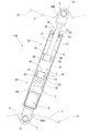
- the fall prevention device of the second embodiment is implemented such that the second piston 80 is not stored in the second cylinder portion 30 of the damper 110 and the bag body 180 filled with the gas G is stored.
- the same configurations are denoted by the same reference numerals and detailed description thereof is omitted.
- the damper 110 of this overturn prevention device houses a bag body 180 filled with gas G on the closed end side of the second cylinder part 30.
- the bag body 180 is fixed to the closed end of the second cylinder part 30.
- the bag body 180 has elasticity. For this reason, in this damper 110, the bag body 180 occupies most of the internal space of the second cylinder part 30 in the most extended state. Further, in this fall prevention device, when the furniture F is tilted by a shake such as an earthquake and the damper 110 is contracted, the hydraulic oil Y filled in the second chamber C2 flows through the third communication passage 61 of the first piston 60. It flows into the first chamber C1.
- the damper 110 when the damper 110 is contracted, the volume occupied by the rod 70 in the first cylinder portion 20 increases due to the rod 70 entering the first cylinder portion 20, so that the amount of hydraulic oil Y equal to the volume is
- the second chamber C2 flows through the first communication passage 43 of the partition member 40 and flows between the bag body 180 and the partition member 40.
- this overturn prevention device As the hydraulic oil Y between the bag body 180 and the partition member 40 increases, the bag body 180 filled with the gas G is compressed. For this reason, when the damper 110 contracts, this overturn prevention device increases the expansion force of the bag body 180, and the force that pushes back the hydraulic oil Y from the second cylinder part 30 to the second chamber C2 of the first cylinder part 20. To increase. As described above, in the fall prevention device, when the damper 110 contracts, the expansion force of the bag body 180 acts in the extending direction.
- the hydraulic oil Y filled in the first chamber C1 is supplied to the third communication passage 61 of the first piston 60 and the fourth communication passage 63 provided with the check valve. And flows into the second chamber C2.
- the damper 110 is extended, the volume occupied by the rod 70 in the first cylinder portion 20 is reduced due to the rod 70 retracting from the first cylinder portion 20, so that the amount of hydraulic oil Y equal to that volume is Then, the air flows into the second chamber C2 from between the bag body 180 and the partition member 40 through the first communication passage 43 of the partition member 40 and the second communication passage 45 provided with the check valve 47.
- the damper 110 of this overturn prevention device acts as a volume compensation portion, and the first cylinder portion 20 is maintained in a state filled with the hydraulic oil Y.
- the damper 110 of the overturn prevention device has a bag body 180 filled with the gas G without any resistance in the extending direction because the hydraulic oil Y flows through the second communication passage 45 and the fourth communication passage 63 during the extension operation. It can be smoothly extended by the expansion force. For this reason, the damper 110 of this fall prevention device can reliably follow the inclination of the furniture F caused by shaking such as an earthquake.
- the damper 110 can always generate a damping force. Therefore, in this fall prevention device, when the furniture F tilts due to shaking such as an earthquake, the damper 110 generates a damping force in the entire stroke range, and the damping force of the damper 110 always acts on the furniture F, and the furniture F Falling can be prevented.
- the damper 110 that constitutes the overturn prevention device of the second embodiment includes the first cylinder part 20, the second cylinder part 30, the partition member 40, the rod guide 50, the first piston 60, the rod 70, and the first cylinder part.
- Two pistons 80 are provided.
- the first cylinder part 20 is cylindrical.
- One end of the second cylinder part 30 is continuous with the first cylinder part 20.
- the second cylinder portion 30 has a cylindrical shape with the other end closed.
- the partition member 40 is provided at a boundary portion between the first cylinder portion 20 and the second cylinder portion 30. Further, the partition member 40 has a first communication passage 43 that communicates the first cylinder part 20 and the second cylinder part 30.
- the rod guide 50 seals the opening 25 opened at the end of the first cylinder part 20.
- the first piston 60 is slidably accommodated in the first cylinder part 20 filled with hydraulic oil Y. Further, the first piston 60 partitions the first cylinder portion 20 into a first chamber C1 and a second chamber C2.
- the base end of the rod 70 is connected to the first piston 60. Further, the rod 70 is slidably inserted through the rod guide 50, and the tip side protrudes outside the first cylinder portion 20.
- the bag body 180 is accommodated in the second cylinder part 30. Moreover, the bag body 180 is filled with the gas G inside.
- the second cylinder part 30 acts as a volume compensation part, maintains the state in which the hydraulic oil Y is filled in the first cylinder part 20, and is filled with the hydraulic oil Y. Since the piston moves in one cylinder part 20, a damping force can always be generated.
- the damper 110 can generate a damping force over the entire stroke range.
- the communication path of the partition member 40 includes a first communication path 43 that provides resistance to the hydraulic oil Y that flows between the first cylinder part 20 and the second cylinder part 30, and a second cylinder part. And a second communication passage 45 provided with a check valve 47 that allows only the flow of hydraulic oil Y from 30 to the first cylinder portion 20.
- the first piston 60 includes a third communication passage 61 that provides resistance to the hydraulic oil Y flowing between the first chamber C1 and the second chamber C2, and hydraulic oil from the first chamber C1 to the second chamber C2.
- a fourth communication path 63 provided with a check valve 65 that allows only the flow of Y. For this reason, the damper 110 can generate a damping force in the entire stroke during the contracting operation.
- the damper 110 since the hydraulic oil Y flows through the second communication path 45 and the fourth communication path 63 when the damper 110 is extended, the damper 110 has no resistance in the extension direction and is expanded by the expansion force of the bag body 180 filled with the gas G. Can stretch smoothly. For this reason, if this damper 110 is attached between the upper surface of the furniture F installed on the floor and the ceiling T, it is possible to reliably follow the inclination of the furniture F due to shaking such as an earthquake.
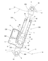
- the fall prevention device of the third embodiment is different from the first embodiment in that the first cylinder portion 220 and the second cylinder portion 230 of the damper 210 are arranged in parallel.
- Other configurations are the same as those of the first embodiment, and the same configurations are denoted by the same reference numerals and detailed description thereof is omitted.
- the damper 210 of this overturn prevention device is provided in the order of the first cylinder part 220, the partition member 40, the communication part R, and the second cylinder part 230.
- the partition member 40 and the communication portion R are provided at the boundary between the first cylinder portion 220 and the second cylinder portion 230.
- the communication part R communicates the first cylinder part 220 and the second cylinder part 230 via the first communication path 43 and the second communication path 45 of the partition member 40.
- the first cylinder part 220 and the second cylinder part 230 are arranged in parallel.
- the communication portion R has the lower end portion of the first cylinder portion 220 and the lower end portion of the second cylinder portion 230 in a state where the fall prevention device is attached between the upper surface of the furniture F and the ceiling T. And communicate with.
- the communication part R forms a connection surface 225 orthogonal to the central axis of the first cylinder part 220 and the rod 70.
- the fall prevention device connects one joint portion 90A to the connection surface 225 so that the center of the through hole 91 of the joint portion 90A is positioned on the central axis of the first cylinder portion 220 and the rod 70.
- the fall prevention device connects the other joint portion 90 ⁇ / b> B to the tip of the rod 70.
- the rod 70 protrudes upward from the first cylinder part 220, and the central axis of the first cylinder part 220 and the rod 70 is at an angle between 65 ° and 75 ° with respect to the horizontal plane. It attaches between the upper surface of the furniture F and the ceiling T so that it may incline.
- the fall prevention device attached between the upper surface of the furniture F and the ceiling T has the hydraulic oil Y filled in the second chamber C2 when the furniture F is tilted and the damper 210 is contracted by a shake such as an earthquake.
- the damper 210 is contracted, the volume occupied by the rod 70 in the first cylinder portion 220 is increased by the rod 70 entering the first cylinder portion 220.
- the second chamber C2 flows through the first communication passage 43 and the communication portion R of the partition member 40 and flows into the third chamber C3 formed in the second cylinder portion 230.
- the damper 210 generates a damping force.
- the hydraulic oil Y filled in the first chamber C1 is provided with the third communication path 61 of the first piston 60 and the fourth communication path provided with the check valve 65. 63 and flows into the second chamber C2.
- the damper 210 when the damper 210 is extended, the volume occupied by the rod 70 in the first cylinder part 220 is reduced by the rod 70 retracting from the first cylinder part 220, so that the amount of hydraulic oil Y equal to the volume of the rod 70 is increased. From the third chamber C3, it flows into the second chamber C2 through the communication portion R and the first communication passage 43 of the partition member 40 and the second communication passage 45 provided with the check valve 47.
- the damper 210 of this overturn prevention device acts as a volume compensation portion, and the first cylinder portion 220 is maintained in a state filled with the hydraulic oil Y. Further, the damper 210 of this overturn prevention device is filled in the fourth chamber C4 without resistance in the extending direction because the hydraulic oil Y flows through the second communication passage 45 and the fourth communication passage 63 during the extension operation. The gas G can be smoothly extended by the expansion force. For this reason, the damper 210 of this fall prevention device can reliably follow the inclination of the furniture F caused by shaking such as an earthquake.
- the damper 210 can always generate a damping force. Therefore, in this fall prevention device, when the furniture F tilts due to shaking such as an earthquake, the damper 210 generates a damping force over the entire stroke range, and the damping force of the damper 210 always acts on the furniture F, and the furniture F Falling can be prevented.
- the damper 210 constituting the overturn prevention device of the third embodiment includes the first cylinder part 220, the second cylinder part 230, the partition member 40, the rod guide 50, the first piston 60, the rod 70, and the first cylinder part 220.
- Two pistons 80 are provided.
- the first cylinder part 220 is cylindrical.
- One end of the second cylinder part 230 is continuous with the first cylinder part 220.
- the second cylinder part 230 has a cylindrical shape with the other end closed.
- the partition member 40 is provided at the boundary between the first cylinder part 220 and the second cylinder part 230.
- the partition member 40 has a first communication path 43 that communicates the first cylinder part 220 and the second cylinder part 230.
- the rod guide 50 seals the opening opened at the end of the first cylinder part 220.
- the first piston 60 is slidably accommodated in the first cylinder part 220 filled with hydraulic oil Y. Further, the first piston 60 partitions the first cylinder part 220 into a first chamber C1 and a second chamber C2.
- the base end of the rod 70 is connected to the first piston 60.
- the rod 70 is slidably inserted through the rod guide 50, and the tip side protrudes outside the first cylinder part 220.
- the second piston 80 is slidably accommodated in the second cylinder part 230.
- the second piston 80 communicates with the second chamber C2 and divides the inside of the second cylinder portion 230 into a third chamber C3 filled with hydraulic oil Y and a fourth chamber C4 filled with gas G. .
- the second cylinder part 230 acts as a volume compensation part, maintains the state in which the hydraulic oil Y is filled in the first cylinder part 220, and is filled with the hydraulic oil Y. Since the piston moves in one cylinder part 220, a damping force can always be generated.
- the damper 210 can generate a damping force over the entire stroke range.
- the damper 210 includes a communication portion R that communicates the first cylinder portion 220 and the second cylinder portion 230 so that the first cylinder portion 220 and the second cylinder portion 230 are arranged in parallel. For this reason, this damper 210 can shorten a full length.
- the communication path of the partition member 40 includes a first communication path 43 that provides resistance to the hydraulic oil Y that flows between the first cylinder part 220 and the second cylinder part 230, and a second cylinder part. 230 and a second communication passage 45 provided with a check valve 47 that allows only the flow of hydraulic oil Y from the first cylinder portion 220 to the first cylinder portion 220.
- the first piston 60 includes a third communication passage 61 that provides resistance to the hydraulic oil Y flowing between the first chamber C1 and the second chamber C2, and hydraulic oil from the first chamber C1 to the second chamber C2.
- a fourth communication path 63 provided with a check valve 65 that allows only the flow of Y.
- the damper 210 can generate a damping force in the entire stroke during the contracting operation.
- the hydraulic oil Y flows through the second communication passage 45 and the fourth communication passage 63 when the damper 210 is extended, there is no resistance in the extension direction and the expansion of the gas G filled in the fourth chamber C4. It can stretch smoothly by force. For this reason, if this damper 10 is attached between the upper surface of the furniture F installed on the floor surface and the ceiling T, the inclination of the furniture F due to shaking such as an earthquake can be reliably followed.
- the fall prevention device of the fourth embodiment is implemented such that the second piston 80 is not stored in the second cylinder portion 230 of the damper 310 and the bag body 380 filled with the gas G is stored. This is different from Form 3.
- Other configurations are the same as those of the third embodiment, and the same configurations are denoted by the same reference numerals and detailed description thereof is omitted.
- the damper 310 of this overturn prevention device houses a bag body 380 filled with gas G on the closed end side of the second cylinder portion 230. Since the bag body 380 is filled with the gas G, the bag body 380 is in close contact with the closed end portion of the second cylinder portion 230 by buoyancy in a state where the fall prevention device is attached between the upper surface of the furniture F and the ceiling T. . Thus, this overturn prevention device does not require the trouble of fixing the bag body 380 to the closed end portion of the second cylinder portion 230.
- the bag body 380 has elasticity.
- the bag body 380 occupies most of the internal space of the second cylinder 230 in the most extended state. Further, in this fall prevention device, when the furniture F is tilted by a shake such as an earthquake and the damper 310 is contracted, the hydraulic oil Y filled in the second chamber C2 flows through the third communication passage 61 of the first piston 60. It flows into the first chamber C1.
- the damper 310 when the damper 310 is contracted, the volume occupied by the rod 70 in the first cylinder part 220 increases due to the rod 70 entering the first cylinder part 220, so that the amount of hydraulic oil Y equal to that volume is From the second chamber C2, it flows through the first communication passage 43 and the communication portion R of the partition member 40 and flows into the second cylinder portion 230 while compressing the bag body 380.
- the bag body 380 filled with the gas G is compressed as the hydraulic oil Y in the second cylinder part 230 increases.
- the damper 310 contracts, the expansion force of the bag body 380 increases, and the force that pushes back the hydraulic oil Y from the second cylinder part 230 to the second chamber C2 of the first cylinder part 220.
- the expansion force of the bag body 380 acts in the extending direction.
- the hydraulic oil Y filled in the first chamber C1 is provided with the third communication path 61 of the first piston 60 and the fourth communication path provided with the check valve 65. 63 and flows into the second chamber C2.
- the damper 310 when the damper 310 is extended, the volume occupied by the rod 70 in the first cylinder part 220 is reduced by the rod 70 retracting from the first cylinder part 220, so that the amount of hydraulic oil Y equal to the volume of the oil is reduced.
- the second cylinder portion 230 flows into the second chamber C2 through the communication portion R, the first communication passage 43 of the partition member 40, and the second communication passage 45 provided with the check valve 47.
- the damper 310 of this overturn prevention device acts as a volume compensation part, and the first cylinder part 220 is maintained in a state filled with the hydraulic oil Y.
- the damper 310 of this overturn prevention device has the hydraulic oil Y flowing through the second communication passage 45 and the fourth communication passage 63 during the extension operation, so there is no resistance in the extension direction and the bag body 180 filled with the gas G. It can be smoothly extended by the expansion force. For this reason, the damper 310 of this fall prevention device can reliably follow the inclination of the furniture F caused by shaking such as an earthquake.
- the damper 310 can always generate a damping force. Therefore, in this fall prevention device, when the furniture F tilts due to shaking such as an earthquake, the damper 310 generates a damping force in the entire stroke range, and the damping force of the damper 310 always acts on the furniture F, and the furniture F Falling can be prevented.
- the damper 310 constituting the overturn prevention device of the fourth embodiment includes the first cylinder part 220, the second cylinder part 230, the partition member 40, the rod guide 50, the first piston 60, the rod 70, and the first cylinder part 220.
- Two pistons 80 are provided.
- the first cylinder part 220 is cylindrical.
- One end of the second cylinder part 230 is continuous with the first cylinder part 220.
- the second cylinder part 230 has a cylindrical shape with the other end closed.
- the partition member 40 is provided at the boundary between the first cylinder part 220 and the second cylinder part 230.
- the partition member 40 has a first communication path 43 that communicates the first cylinder part 220 and the second cylinder part 230.
- the rod guide 50 seals the opening opened at the end of the first cylinder part 220.
- the first piston 60 is slidably accommodated in the first cylinder part 220 filled with hydraulic oil Y. Further, the first piston 60 partitions the first cylinder part 220 into a first chamber C1 and a second chamber C2.
- the base end of the rod 70 is connected to the first piston 60.
- the rod 70 is slidably inserted through the rod guide 50, and the tip side protrudes outside the first cylinder part 220.
- the bag body 380 is accommodated in the second cylinder part 230. Further, the bag body 380 is filled with a gas G.
- the second cylinder part 230 acts as a volume compensation part, maintains the state in which the hydraulic oil Y is filled in the first cylinder part 220, and is filled with the hydraulic oil Y. Since the piston moves in one cylinder part 220, a damping force can always be generated.
- the damper 310 can generate a damping force over the entire stroke range.
- the damper 310 includes a communication portion R that connects the first cylinder portion 220 and the second cylinder portion 230 so that the first cylinder portion 220 and the second cylinder portion 230 are arranged in parallel. For this reason, this damper 310 can shorten a full length.
- the communication path of the partition member 40 includes a first communication path 43 that provides resistance to the hydraulic oil Y flowing between the first cylinder part 220 and the second cylinder part 230, and a second cylinder part. 230 and a second communication passage 45 provided with a check valve 47 that allows only the flow of hydraulic oil Y from the first cylinder portion 220 to the first cylinder portion 220.
- the first piston 60 includes a third communication passage 61 that provides resistance to the hydraulic oil Y flowing between the first chamber C1 and the second chamber C2, and hydraulic oil from the first chamber C1 to the second chamber C2.
- a fourth communication path 63 provided with a check valve 65 that allows only the flow of Y.
- the damper 310 can generate a damping force in the entire stroke during the contracting operation.
- the damper 310 since the hydraulic oil Y flows through the second communication passage 45 and the fourth communication passage 63 when the damper 310 is extended, the damper 310 has no resistance in the extension direction and is expanded by the expansion force of the bag body 380 filled with the gas G. Can stretch smoothly. For this reason, if this damper 310 is attached between the upper surface of the furniture F installed on the floor and the ceiling T, it is possible to reliably follow the inclination of the furniture F due to shaking such as an earthquake.
- the present invention is not limited to Embodiments 1 to 4 described with reference to the above description and drawings.
- the following embodiments are also included in the technical scope of the present invention.
- the hydraulic oil is sealed in the cylinder.
- the fourth chamber is filled with gas.
- the fourth chamber may be compressed and filled.
- the bag body is filled with gas, but the bag body may be compressed and filled with gas.
- the pressure damper is used, but it may be a bilateral or elongation damper. In this case, a check valve or the like provided on the first piston and the partition member is changed.
- the first cylinder part and the second cylinder part are arranged in parallel, but they may be arranged so that the central axes of the first cylinder part and the second cylinder part intersect each other. .
Landscapes
- Engineering & Computer Science (AREA)
- General Engineering & Computer Science (AREA)
- Mechanical Engineering (AREA)
- Vibration Prevention Devices (AREA)
- Fluid-Damping Devices (AREA)
- Buildings Adapted To Withstand Abnormal External Influences (AREA)
Abstract
L'invention concerne un amortisseur qui génère une force d'amortissement pendant toute sa course. Un amortisseur (10) comprend une première section de cylindre (20), une seconde section de cylindre (30), un élément de séparation (40), un guide de tige (50), un premier piston (60), une tige (70) et un second piston (80). L'élément de séparation (40) est disposé à la limite entre la première section de cylindre (20) et la seconde section de cylindre (30). En outre, l'élément de séparation (40) comporte un premier passage de communication (43) pour assurer une communication entre la première section de cylindre (20) et la seconde section de cylindre (30). Le premier piston (60) divise l'intérieur de la première section de cylindre (20) en une première chambre (C1) et une deuxième chambre (C2). Le second piston (80) divise l'intérieur de la seconde section de cylindre (30) en une troisième chambre (C3) en communication avec la deuxième chambre (C2) et remplie d'huile hydraulique (Y), et dans une quatrième chambre (C4) remplie de gaz (G).
Applications Claiming Priority (2)
| Application Number | Priority Date | Filing Date | Title |
|---|---|---|---|
| JP2016063346A JP2017180493A (ja) | 2016-03-28 | 2016-03-28 | ダンパ及びこのダンパを備えた転倒防止装置 |
| JP2016-063346 | 2016-03-28 |
Publications (1)
| Publication Number | Publication Date |
|---|---|
| WO2017169295A1 true WO2017169295A1 (fr) | 2017-10-05 |
Family
ID=59964145
Family Applications (1)
| Application Number | Title | Priority Date | Filing Date |
|---|---|---|---|
| PCT/JP2017/006290 Ceased WO2017169295A1 (fr) | 2016-03-28 | 2017-02-21 | Amortisseur et dispositif anti-chute pourvu dudit amortisseur |
Country Status (3)
| Country | Link |
|---|---|
| JP (1) | JP2017180493A (fr) |
| TW (1) | TW201738477A (fr) |
| WO (1) | WO2017169295A1 (fr) |
Families Citing this family (2)
| Publication number | Priority date | Publication date | Assignee | Title |
|---|---|---|---|---|
| JP6487593B1 (ja) * | 2018-07-06 | 2019-03-20 | Kyb株式会社 | 転倒防止装置 |
| CN111156277A (zh) * | 2020-03-06 | 2020-05-15 | 江苏容大减震科技股份有限公司 | 基于流体、压缩原理的串联式阻尼器及其工作方法 |
Citations (4)
| Publication number | Priority date | Publication date | Assignee | Title |
|---|---|---|---|---|
| JPS4989593U (fr) * | 1972-11-22 | 1974-08-02 | ||
| JPS648440U (fr) * | 1987-07-06 | 1989-01-18 | ||
| JPH102365A (ja) * | 1996-06-14 | 1998-01-06 | Toyota Motor Corp | 液圧緩衝装置 |
| JP2015006330A (ja) * | 2013-05-29 | 2015-01-15 | カヤバ工業株式会社 | 転倒防止装置 |
Family Cites Families (1)
| Publication number | Priority date | Publication date | Assignee | Title |
|---|---|---|---|---|
| JPS5618440U (fr) * | 1979-07-20 | 1981-02-18 |
-
2016
- 2016-03-28 JP JP2016063346A patent/JP2017180493A/ja active Pending
-
2017
- 2017-02-21 WO PCT/JP2017/006290 patent/WO2017169295A1/fr not_active Ceased
- 2017-03-10 TW TW106107953A patent/TW201738477A/zh unknown
Patent Citations (4)
| Publication number | Priority date | Publication date | Assignee | Title |
|---|---|---|---|---|
| JPS4989593U (fr) * | 1972-11-22 | 1974-08-02 | ||
| JPS648440U (fr) * | 1987-07-06 | 1989-01-18 | ||
| JPH102365A (ja) * | 1996-06-14 | 1998-01-06 | Toyota Motor Corp | 液圧緩衝装置 |
| JP2015006330A (ja) * | 2013-05-29 | 2015-01-15 | カヤバ工業株式会社 | 転倒防止装置 |
Also Published As
| Publication number | Publication date |
|---|---|
| TW201738477A (zh) | 2017-11-01 |
| JP2017180493A (ja) | 2017-10-05 |
Similar Documents
| Publication | Publication Date | Title |
|---|---|---|
| JP6353867B2 (ja) | 転倒防止装置 | |
| CN106604662A (zh) | 翻倒防止装置及其安装方法 | |
| WO2017169295A1 (fr) | Amortisseur et dispositif anti-chute pourvu dudit amortisseur | |
| JP5864068B1 (ja) | 転倒防止装置 | |
| CN106714618A (zh) | 翻倒防止装置 | |
| JP6722468B2 (ja) | ダンパ及びこのダンパを備えた転倒防止装置 | |
| CN108024633A (zh) | 防倾翻装置及其安装方法 | |
| JP5864066B1 (ja) | 転倒防止装置 | |
| US20190021499A1 (en) | Overturn preventing device | |
| JP6205445B2 (ja) | 転倒防止装置、及びその取り付け方法 | |
| JP6469291B1 (ja) | 転倒防止装置 | |
| JP6487593B1 (ja) | 転倒防止装置 | |
| JP6386087B2 (ja) | 制振棚 | |
| JP6255458B1 (ja) | 転倒防止装置 | |
| JP2017225539A (ja) | 転倒防止装置 | |
| WO2018123375A1 (fr) | Dispositif anti-basculement | |
| JP2017169853A (ja) | 転倒防止装置 | |
| JP2017169854A (ja) | 連結部材及び転倒防止装置 | |
| WO2017130445A1 (fr) | Dispositif anti-renversement | |
| JP2016063992A (ja) | 転倒防止装置用取付け具及び転倒防止装置 | |
| JP2017176218A (ja) | 転倒防止装置 |
Legal Events
| Date | Code | Title | Description |
|---|---|---|---|
| NENP | Non-entry into the national phase |
Ref country code: DE |
|
| 121 | Ep: the epo has been informed by wipo that ep was designated in this application |
Ref document number: 17773843 Country of ref document: EP Kind code of ref document: A1 |
|
| 122 | Ep: pct application non-entry in european phase |
Ref document number: 17773843 Country of ref document: EP Kind code of ref document: A1 |