WO2017169320A1 - Vanne électrique et système de cycle de refroidissement - Google Patents
Vanne électrique et système de cycle de refroidissement Download PDFInfo
- Publication number
- WO2017169320A1 WO2017169320A1 PCT/JP2017/006553 JP2017006553W WO2017169320A1 WO 2017169320 A1 WO2017169320 A1 WO 2017169320A1 JP 2017006553 W JP2017006553 W JP 2017006553W WO 2017169320 A1 WO2017169320 A1 WO 2017169320A1
- Authority
- WO
- WIPO (PCT)
- Prior art keywords
- valve
- valve body
- press
- guide member
- shaft holder
- Prior art date
- Legal status (The legal status is an assumption and is not a legal conclusion. Google has not performed a legal analysis and makes no representation as to the accuracy of the status listed.)
- Ceased
Links
Images




Classifications
-
- F—MECHANICAL ENGINEERING; LIGHTING; HEATING; WEAPONS; BLASTING
- F16—ENGINEERING ELEMENTS AND UNITS; GENERAL MEASURES FOR PRODUCING AND MAINTAINING EFFECTIVE FUNCTIONING OF MACHINES OR INSTALLATIONS; THERMAL INSULATION IN GENERAL
- F16K—VALVES; TAPS; COCKS; ACTUATING-FLOATS; DEVICES FOR VENTING OR AERATING
- F16K31/00—Actuating devices; Operating means; Releasing devices
- F16K31/02—Actuating devices; Operating means; Releasing devices electric; magnetic
- F16K31/04—Actuating devices; Operating means; Releasing devices electric; magnetic using a motor
-
- F—MECHANICAL ENGINEERING; LIGHTING; HEATING; WEAPONS; BLASTING
- F16—ENGINEERING ELEMENTS AND UNITS; GENERAL MEASURES FOR PRODUCING AND MAINTAINING EFFECTIVE FUNCTIONING OF MACHINES OR INSTALLATIONS; THERMAL INSULATION IN GENERAL
- F16K—VALVES; TAPS; COCKS; ACTUATING-FLOATS; DEVICES FOR VENTING OR AERATING
- F16K31/00—Actuating devices; Operating means; Releasing devices
- F16K31/44—Mechanical actuating means
- F16K31/50—Mechanical actuating means with screw-spindle or internally threaded actuating means
Definitions
- the present invention relates to an electric valve used in a refrigeration cycle and the like, and a refrigeration cycle system using the electric valve.
- a flow control valve used for large packaged air conditioners and refrigerators is known (for example, see Patent Document 1).
- This flow control valve has good operability even when a large diameter and high pressure difference occur because of the rationalization of control equipment such as combining multiple motorized valves used for flow control into one. Performance that can be demonstrated is desired, but flow control with a relatively large bore has a large load on the valve body due to the pressure difference compared to the thrust of the screw generated by the torque of the magnet, and is large to operate the valve body. Driving force is required.
- the seal member 137 is attached to the valve body 120 that is in sliding contact with the inner peripheral surface of the cylindrical holding member 114, and the back pressure chamber 129 is defined above the valve chamber 107.
- the pressure in the valve port 119 is introduced into the back pressure chamber 129 via the conduction path 124 provided in the valve body 120, and the pressure in the back pressure chamber 129 (back pressure) is used to close the valve. Canceling the force due to the pressure difference between the push-down force (force acting in the valve closing direction) acting on the valve body 120 in the state and the push-up force (force acting in the valve opening direction), and reducing the load on the valve body 120 Yes.
- valve shaft holder 106 In this flow control valve, it is necessary to assemble the valve shaft holder 106, the cylindrical holding member 114, and the valve main body 130 with high accuracy in order to prevent valve leakage and improve durability.
- the stepped portion 114b formed in the cylindrical holding member 114 is not valved.
- the cylindrical holding member 114 and the valve main body 130 are fixed by brazing while ensuring airtightness and pressure-resistant strength by engaging with a stepped portion 130a formed on the main body 130. Even in this case, in order to ensure concentricity between the cylindrical holding member 114 and the valve main body 130 during assembly, a highly accurate dimensional tolerance is required.
- An object of the present invention is to provide an electric valve capable of easily ensuring concentricity between members, and a refrigeration cycle system using the electric valve.
- the motor-operated valve of the present invention is The rotational motion of the rotor is converted into a linear motion by screw connection between the male screw member and the female screw member, and the valve body accommodated in the valve body is axially guided by the valve body guide member based on this linear motion.
- a motor-operated valve that moves and provides a back pressure chamber above the valve body, and introduces pressure in the valve port into the back pressure chamber,
- the female screw member is assembled by being press-fitted into the valve body guide member or the valve body.
- the motor operated valve of the present invention is The female screw member is press-fitted into the valve body guide member, and further, the valve body guide member is press-fitted into the valve body and assembled.
- the concentricity of the valve main body, the valve body guide member, and the female screw member (valve shaft holder) can be easily secured, and the valve main body, the valve body guide member, and the female body can be secured.
- the screw member (valve shaft holder) is accurately positioned and fixed.
- the motor operated valve of the present invention is By providing a step in the valve body guide member, the valve body guide member is formed with a first press-fit portion and a second press-fit portion having a smaller diameter than the first press-fit portion due to the step, The valve body guide member is assembled to the valve body by press-fitting the first press-fit portion into the valve body; The female screw member is press-fitted into the second press-fitting portion of the valve element guide member and is assembled to the valve body.
- valve body guide member by forming a step in the valve body guide member, spaces are formed between the first press-fit portion and the female screw member (valve shaft holder), and between the second press-fit portion and the valve body, respectively.
- the valve element guide member can be elastically deformed in the radial direction. For this reason, the valve body guide member can be smoothly pressed into the valve body, and the female screw member (valve shaft holder) can be smoothly pressed into the valve body guide member, so that the motor-operated valve can be easily assembled. Further, by providing a step in the valve body guide member to form a space, even if the valve body guide member and the female screw member (valve shaft holder) are tilted during the press-fitting process, the valve body guide member is moved in the radial direction.
- valve body guide member and female screw member (valve shaft holder) are not assembled while being tilted, and the concentricity of the valve body, valve body guide member, and female screw member (valve shaft holder). Can be secured accurately.
- the motor operated valve of the present invention is
- the valve body guide member is a metal part configured separately from the female screw member.
- the slidability of a valve body can be improved by comprising a valve body guide member with a metal.
- the refrigeration cycle system of the present invention A refrigeration cycle system including a compressor, a condenser, an expansion valve, an evaporator, and the like, wherein the above-described electric valve is used as the expansion valve.
- FIG. 3 is a cross-sectional view of a conventional flow control valve disclosed in Japanese Patent Laid-Open No. 2014-35006. It is a principal part expanded sectional view of the conventional flow control valve shown in FIG.
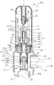
- FIG. 1 is a cross-sectional view showing a motor-operated valve 2 according to the first embodiment.
- “upper” or “lower” is defined in the state of FIG. That is, the rotor 4 is positioned above the valve body 17.
- the valve main body 30 is integrally connected by welding or the like below the opening side of a case 60 made of a non-magnetic material and having a cylindrical cup shape.
- the valve body 30 is a press-molded product manufactured by pressing a metal material such as a stainless steel plate, and has a valve chamber 11 therein.
- the valve body 30 is fixedly mounted with a first pipe joint 12 made of stainless steel or copper that directly communicates with the valve chamber 11.
- a valve seat member 30 ⁇ / b> A in which a valve port 16 having a circular cross section is formed is incorporated in the lower inside of the valve body 30.
- a stainless steel or copper second pipe joint 15 communicating with the valve chamber 11 via the valve port 16 is fixedly attached to the valve seat member 30A.
- Rotating rotor 4 is accommodated in the inner periphery of case 60, and valve shaft 41 is disposed on the shaft core portion of rotor 4 via bush member 33.
- the valve shaft 41 and the rotor 4 coupled by the bush member 33 move integrally in the vertical direction while rotating.
- a male screw 41 a is formed on the outer peripheral surface near the middle portion of the valve shaft 41.
- the valve shaft 41 functions as a male screw member.
- a stator including a yoke, a bobbin, and a coil (not shown) is arranged, and the rotor 4 and the stator constitute a stepping motor.
- a guide support 52 is fixed to the ceiling surface of the case 60.
- the guide support body 52 has a cylindrical portion 53 and an umbrella-shaped portion 54 formed on the upper end side of the cylindrical portion 53, and the whole is integrally formed by press working.
- the umbrella-shaped portion 54 is molded in substantially the same shape as the inside of the top portion of the case 60.
- a cylindrical member 65 that also serves as a guide for the valve shaft 41 is fitted in the cylindrical portion 53 of the guide support 52.
- the cylindrical member 65 is made of a material containing a lubricant or a surface-treated member made of metal or synthetic resin, and rotatably holds the valve shaft 41.
- valve shaft holder 6 that has a function of forming a screw coupling A with the valve shaft 41 and suppressing the inclination of the valve shaft 41 as will be described later. It is fixed to be relatively non-rotatable.
- FIG. 2 is a view showing the structure of the valve shaft holder 6.
- 2A is a side view of the valve shaft holder 6
- FIG. 2B is a top view of the valve shaft holder 6 viewed from above.
- FIG. 2C is a bottom view when viewed from below
- FIG. 2D is a cross-sectional view taken along line AA in FIG. 2B.
- the valve shaft holder 6 is fitted with an upper cylindrical small-diameter portion 6a, a lower cylindrical large-diameter portion 6b, and a fitting portion 6c accommodated on the inner peripheral side of the valve body 30.
- This is a member composed of a flange portion 6f protruding from the joint portion 6c.
- the cylindrical small-diameter portion 6a, the cylindrical large-diameter portion 6b, and the fitting portion 6c are made of a resin material such as PPS (polyphenylene sulfide) resin
- the flange portion 6f is made of a metal such as stainless steel. Is formed.
- the fitting part 6c is provided with the protrusion part 6c1 which protrudes to an outer periphery four directions. Furthermore, the maximum outer diameter of the fitting portion 6 c formed by the outer wall surface of the protruding portion 6 c 1 is formed so as not to be smaller than the diameter on the inner peripheral surface side of the valve body 30. For this reason, when the valve shaft holder 6 is press-fitted into the valve body guide member 72, the protruding portion 6c1 of the valve shaft holder 6 can be closely locked to the inner peripheral surface of the large diameter portion 72a of the valve body guide member 72. The valve shaft holder 6 can be prevented from moving relative to the valve element guide member 72.
- the flange portion 6f has a ring shape that surrounds the lower end of the cylindrical large-diameter portion 6b.
- a female screw 6d is formed downward from the upper opening 6g of the cylindrical small diameter portion 6a of the valve shaft holder 6 to a predetermined depth.
- the valve shaft holder 6 functions as a female screw member. 1 is configured by the male screw 41a formed on the outer periphery of the valve shaft 41 and the female screw 6d formed on the inner periphery of the cylindrical small diameter portion 6a of the valve shaft holder 6. Yes.
- a housing chamber 6 h for housing the valve guide 18 is formed inside the valve shaft holder 6.
- a pressure equalizing hole 51 is formed in the side surface of the cylindrical large diameter portion 6b of the valve shaft holder 6, and the valve in the cylindrical large diameter portion 6b is formed by the pressure equalizing hole 51 as shown in FIG.
- the shaft holder chamber 83 and the rotor accommodating chamber 67 (second back pressure chamber) communicate with each other.
- a cylindrical valve guide 18 is disposed below the valve shaft 41 so as to be slidable with respect to the storage chamber 6 h of the valve shaft holder 6.
- the valve guide 18 is bent at a substantially right angle on the ceiling 21 side by press molding.
- a through hole 18 a is formed in the ceiling portion 21.
- a flange 41 b is further formed below the valve shaft 41.
- valve shaft 41 is inserted into the through hole 18a of the valve guide 18 so as to be rotatable with respect to the valve guide 18 and displaceable in the radial direction. It arrange
- valve shaft 41 is inserted through the through hole 18 a and is arranged so that the upper surface of the flange portion 41 b faces the ceiling portion 21 of the valve guide 18.
- the flange 41b is larger in diameter than the through hole 18a of the valve guide 18 so that the valve shaft 41 is prevented from coming off.
- valve shaft 41 and the valve guide 18 are movable in the radial direction with respect to each other, the valve guide 18 and the valve guide 18 and the valve shaft 41 are not required to have a high degree of concentric mounting accuracy with respect to the arrangement positions of the valve shaft holder 6 and the valve shaft 41. Concentricity with the valve body 17 is obtained.
- a washer 70 having a through-hole formed at the center is installed between the ceiling portion 21 of the valve guide 18 and the flange portion 41b of the valve shaft 41.
- the washer 70 is preferably a metal washer having a highly slippery surface, a highly slippery resin washer such as a fluororesin, or a metal washer having a highly slippery resin coating. Further, a compressed valve spring 27 and a spring receiver 35 are accommodated in the valve guide 18.
- valve body guide member 72 that guides the movement of the valve body 17 in the axial direction is disposed inside the valve body 30, and a seal member 48 is interposed between the valve body 17 and the valve body guide member 72. It is intervened.
- a vertical hole 17b and a horizontal conduction hole 17c are formed as a pressure equalizing path.
- the pressure in the valve port 16 (in the second pipe joint 15) is guided to the back pressure chamber 28 through the hole 17b and the conduction hole 17c which are pressure equalization paths.
- the valve body guide member 72 is a metal cylinder through which the inside penetrates, and has a flange portion 72c positioned at the uppermost position, a large-diameter portion 72a below it, and a small-diameter portion 72b below it. It is formed by press-molding a metal material such as a stainless steel plate.
- the diameter on the outer peripheral surface side of the large diameter portion 72 a of the valve body guide member 72 is slightly larger than the diameter on the inner peripheral surface side of the valve body 30.
- valve body guide member 72 when the valve body guide member 72 is press-fitted into the valve body 30, the large-diameter portion 72a of the valve body guide member 72 can be closely locked to the inner peripheral surface of the valve body 30, and the valve body guide member 72 is It is possible to prevent the valve body 30 from moving.
- valve body guide member 72 may be formed integrally with the valve shaft holder 6 instead of being an independent part, the valve body guide member 72 is different from the valve shaft holder 6 in the present embodiment. A case where independent parts are used will be described as an example.
- the seal member 48 is an annular member formed by sandwiching an annular reinforcing plate 48b between an annular packing 48a having an L-shaped cross section made of a highly slippery resin material such as PTFE.
- leaf springs that constantly urge the annular packing 48a outward are respectively disposed above the annular packing 48a disposed above and below the annular packing 48a disposed below. Is preferred.
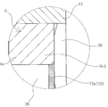
- FIG. 3 is an enlarged cross-sectional view of a main part of the motor-operated valve 2 according to the first embodiment.
- the valve shaft holder 6, the valve body guide member 72, and the valve main body 30 are composed of independent members.
- valve body guide member 72 is press-fitted into the valve body 30 with the outer peripheral surface of the large-diameter portion 72 a contacting the inner peripheral surface of the valve main body 30. Further, the valve shaft holder 6 is press-fitted into the valve body guide member 72 with the protruding portion 6 c 1 protruding from the outer periphery of the fitting portion 6 c in contact with the inner peripheral surface of the large diameter portion 72 a of the valve body guide member 72.
- the bottom surface of the flange portion 6f of the valve shaft holder 6, the upper end portion of the valve main body 30, and the flange portion 72c of the valve element guide member 72 are integrally sealed over the entire circumference by welding. Fixed.
- valve body guide member 72 when the outer peripheral surface of the large-diameter portion 72 a of the valve body guide member 72 is brought into contact with the inner peripheral surface of the valve body 30 and the valve body guide member 72 is press-fitted into the valve body 30, the valve body guide member 72 is Since the valve body guide member 72 can be tightly locked to the valve body 30, the valve body guide member 72 is naturally disposed at a position that is concentric with the valve body 30.
- valve shaft holder 6 when the protruding portion 6c1 of the valve shaft holder 6 is brought into contact with the inner peripheral surface of the large diameter portion 72a of the valve body guide member 72 and the valve shaft holder 6 is press-fitted into the valve body guide member 72, the valve shaft holder 6 Therefore, the valve shaft holder 6 is naturally arranged at a position where it is concentric with the valve body guide member 72.
- the valve main body 30, the valve body guide member 72, and the valve shaft holder 6 can be easily assembled without a high degree of assembly accuracy. Concentricity can be ensured, and positioning and fixing of the valve main body 30, the valve body guide member 72, and the valve shaft holder 6 are performed accurately. For this reason, it is not necessary to use a jig or the like to ensure concentricity. Further, the valve body guide member 72 is tightly locked to the valve body 30, whereby the first chamber 26 formed outside the valve body 17, the back formed by the valve body 17 and the valve shaft holder 6.
- valve body guide member 72 is made of metal and the annular packing 48a of the seal member 48 is made of a highly slipping resin material such as PTFE, the slidability of the valve body 17 can be improved.
- the motor-operated valve according to the second embodiment is obtained by directly press-fitting the valve shaft holder 6 into the valve main body 30 in the first embodiment. Therefore, description of the same configuration as that of the first embodiment is omitted, and only different portions will be described.
- FIG. 4 is a cross-sectional view of the motor-operated valve according to the second embodiment
- FIG. 5 is an enlarged cross-sectional view of the main part thereof.
- the valve shaft holder 6 is formed such that the maximum outer diameter of the fitting portion 6 c formed by the outer wall surface of the protruding portion 6 c 1 is not smaller than the diameter on the inner peripheral surface side of the valve body 30. ing. For this reason, when the valve shaft holder 6 is press-fitted into the valve body 30, the protruding portion 6 c 1 of the valve shaft holder 6 can be closely locked to the inner peripheral surface of the valve body 30, and the valve shaft holder 6 is attached to the valve body 30. In contrast, it can be prevented from moving.
- the valve body guide member 72 has a large diameter portion 72 a and a small diameter portion 72 b below the large diameter portion 72 a, and the diameter on the outer peripheral surface side of the large diameter portion 72 a of the valve body guide member 72 is the inner periphery of the valve body 30. It is formed slightly larger than the diameter on the surface side.
- the valve body guide member 72 used for the motor-operated valve 200 according to the second embodiment does not include the flange portion 72c (see FIG. 1) unlike the motor-operated valve 2 according to the first embodiment.
- the valve body guide member 72 is attached to the lower side of the valve shaft holder 6 by welding the large diameter portion 72 a to the inner peripheral surface of the valve main body 30.
- valve shaft holder 6 causes the protrusion 6 c 1 of the fitting portion 6 c of the valve shaft holder 6 to directly contact the inner peripheral surface of the valve body 30. Is press-fitted into the valve body 30. After press-fitting, the lower surface of the flange portion 6f of the valve shaft holder 6 and the upper end portion of the valve body 30 are fixed in a sealed state over the entire circumference by welding.
- the protrusion 6c1 of the valve shaft holder 6 is brought into direct contact with the inner peripheral surface of the valve body 30 and the valve shaft holder 6 is press-fitted into the valve body guide member 72, the protrusion 6c1 of the valve shaft holder 6 is Since the valve body 30 is closely locked to the valve body 30, the valve shaft holder 6 is naturally disposed at a position that is concentric with the valve body 30.
- the concentricity between the valve body 30 and the valve shaft holder 6 can be easily ensured without a high degree of assembly accuracy.
- the valve body 30 and the valve shaft holder 6 are reliably positioned and fixed.
- the motor-operated valve according to the third embodiment is obtained by providing a step in the valve element guide member 72 in the first embodiment. Therefore, description of the same configuration as that of the first embodiment is omitted, and only different portions will be described.
- FIG. 6 is a cross-sectional view of the motor-operated valve according to the third embodiment.
- the valve element guide member 72 includes a large diameter portion 72a, a lower small diameter portion 72b, and a flange portion 72c. Further, a step 74 is formed in the large diameter portion 72a over the entire circumference.
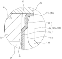
- FIG. 7 is an enlarged cross-sectional view of the vicinity of the step 74 that is a main part of the motor-operated valve 202.
- the large-diameter portion 72 a of the valve element guide member 72 is configured by changing the diameter with the step 74 as a boundary, and a first press-fitted portion 75 formed above the step 74 and a lower portion of the step 74.
- the second press-fitting portion 76 having a smaller diameter than the first press-fitting portion 75 formed in the above is provided.
- a space 82 is formed between the first press-fit portion 75 and the valve shaft holder 6, and the second press-fit portion 76.
- a space 84 is formed between the valve body 30 and the valve body 30.
- the diameter on the outer peripheral surface side of the first press-fit portion 75 is formed slightly larger than the diameter on the inner peripheral surface side of the valve main body 30, when the valve body guide member 72 is press-fitted into the valve main body 30, The portion 75 is closely locked to the inner peripheral surface of the valve body 30.
- the maximum outer diameter of the fitting portion 6c of the valve shaft holder 6 formed by the outer wall surface of the protruding portion 6c1 is formed so as not to be smaller than the diameter on the inner peripheral surface side of the second press-fit portion 76. Therefore, when the valve shaft holder 6 is press-fitted into the valve element guide member 72, the protruding portion 6c1 of the valve shaft holder 6 is closely locked to the inner peripheral surface of the second press-fit portion 76.
- the valve body guide member 72 is press-fitted into the valve main body 30 by bringing the outer peripheral surface of the first press-fit portion 75 of the large-diameter portion 72 a into contact with the inner peripheral surface of the valve main body 30. .
- the first press-fit portion 75 can be contracted in the radial direction by the reaction force of the inner peripheral surface of the valve body 30.
- the valve body guiding member 72 is smoothly press-fitted into the valve body 30 as compared with the case where there is no step 74.
- valve shaft holder 6 brings the protruding portion 6 c 1 protruding from the outer periphery of the fitting portion 6 c into contact with the inner peripheral surface of the second press-fit portion 76 of the large diameter portion 72 a of the valve body guiding member 72. It is press-fitted into.
- the second press-fit portion 76 can be expanded in the radial direction by the protrusion 6c1 of the valve shaft holder 6, and the valve shaft The holder 6 is smoothly press-fitted into the valve element guide member 72.
- the bottom surface of the flange portion 6f of the valve shaft holder 6, the upper end portion of the valve main body 30, and the flange portion 72c of the valve element guide member 72 are integrally sealed over the entire circumference by welding. Fixed.
- the step 74 is provided in the large diameter portion 72a to form the space 82 and the space 84, and the valve body guide member 72 can be elastically deformed in the radial direction.
- the valve body guide member 72 and the valve shaft holder 6 can be smoothly press-fitted into the valve body 30 and the valve body guide member 72, respectively, and the electric valve 202 can be easily assembled.
- valve body guide member 72 Since the guide member 72 is elastically deformed in the radial direction, the valve body guide member 72 and the valve shaft holder 6 are not assembled while being tilted, and each of the valve body 30, the valve body guide member 72, and the valve shaft holder 6 is the same. The core property can be ensured accurately.
- the case where the hole 17b and the conduction hole 17c are provided in the valve body 17 as an example of the pressure equalizing path has been described as an example.
- the pressure equalizing path is not necessarily provided in the valve body 17. It does not have to be provided.
- a piping member that guides the pressure of the valve port 16 to the back pressure chamber 28 may be provided separately.
- the case where an annular member formed by sandwiching an annular reinforcing plate 48b between annular packings 48a having an L-shaped cross section is used as the seal member 48 is described as an example.
- the configuration of the seal member 48 is not necessarily limited to this.
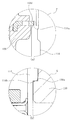
- a composite sealing material in which an O-ring 48d and an annular packing 48f having a C-shaped cross section made of a highly slipping resin material such as PTFE are combined as the sealing member 48 may be adopted.
- the motor-operated valve of each embodiment described above is used as an expansion valve provided between the condenser and the evaporator in a refrigeration cycle system including a compressor, a condenser, an expansion valve, an evaporator, and the like. It is done.
- Valve shaft holder (Female thread member) 6c Fitting portion 6c1 Protruding portion 6d Female thread 17 Valve body 30 Valve body 41 Valve shaft 41a Male thread 48 Seal member 72 Valve body guide member 72a Large diameter portion 72b Small diameter portion 72c Flange portion 74 Step 75 First press-fit portion 76 Second Press-in part 82 space 84 space
Landscapes
- Engineering & Computer Science (AREA)
- General Engineering & Computer Science (AREA)
- Mechanical Engineering (AREA)
- Electrically Driven Valve-Operating Means (AREA)
Abstract
L'objectif de cette invention est d'obtenir une vanne électrique dans laquelle la concentricité entre les éléments peut être facilement maintenue, ainsi qu'un système de cycle de refroidissement mettant en oeuvre cette vanne électrique. Plus spécifiquement, l'invention concerne une vanne électrique d'un type qui, au moyen d'un accouplement à vis entre un élément de vis mâle et un élément de vis femelle, convertit le mouvement rotatif d'un rotor en mouvement rectiligne. Cette vanne électrique provoque le déplacement en direction axiale d'un corps de vanne logé à l'intérieur du corps principal de vanne, grâce au mouvement rectiligne et à l'aide d'un élément guide de corps de vanne, comporte côté supérieur du corps de vanne, une chambre de contre-pression, et introduit dans ladite chambre de contre-pression la pression de l'intérieur d'un orifice de vanne. L'élément de vis femelle est assemblé par ajustement par pression dans l'élément guide de corps de vanne ou dans le corps principal de vanne.
Priority Applications (2)
| Application Number | Priority Date | Filing Date | Title |
|---|---|---|---|
| CN201780015200.6A CN108779870B (zh) | 2016-03-31 | 2017-02-22 | 电动阀以及冷冻循环系统 |
| JP2018508589A JP6722274B2 (ja) | 2016-03-31 | 2017-02-22 | 電動弁および冷凍サイクルシステム |
Applications Claiming Priority (2)
| Application Number | Priority Date | Filing Date | Title |
|---|---|---|---|
| JP2016071247 | 2016-03-31 | ||
| JP2016-071247 | 2016-03-31 |
Publications (1)
| Publication Number | Publication Date |
|---|---|
| WO2017169320A1 true WO2017169320A1 (fr) | 2017-10-05 |
Family
ID=59963072
Family Applications (1)
| Application Number | Title | Priority Date | Filing Date |
|---|---|---|---|
| PCT/JP2017/006553 Ceased WO2017169320A1 (fr) | 2016-03-31 | 2017-02-22 | Vanne électrique et système de cycle de refroidissement |
Country Status (3)
| Country | Link |
|---|---|
| JP (1) | JP6722274B2 (fr) |
| CN (1) | CN108779870B (fr) |
| WO (1) | WO2017169320A1 (fr) |
Cited By (3)
| Publication number | Priority date | Publication date | Assignee | Title |
|---|---|---|---|---|
| WO2023074327A1 (fr) * | 2021-10-25 | 2023-05-04 | ダイキン工業株式会社 | Soupape de réduction de pression, échangeur de chaleur, dispositif de climatisation et procédé de fabrication d'échangeur de chaleur |
| WO2023074328A1 (fr) * | 2021-10-25 | 2023-05-04 | ダイキン工業株式会社 | Échangeur de chaleur, dispositif de climatisation, et procédé de fabrication d'échangeur de chaleur |
| WO2024176737A1 (fr) * | 2023-02-24 | 2024-08-29 | 株式会社不二工機 | Soupape électrique |
Families Citing this family (1)
| Publication number | Priority date | Publication date | Assignee | Title |
|---|---|---|---|---|
| CN111561571B (zh) * | 2019-02-14 | 2023-11-21 | 株式会社Tgk | 电动阀 |
Citations (2)
| Publication number | Priority date | Publication date | Assignee | Title |
|---|---|---|---|---|
| JP2013221640A (ja) * | 2012-04-13 | 2013-10-28 | Daikin Industries Ltd | 空気調和装置 |
| JP2015190497A (ja) * | 2014-03-27 | 2015-11-02 | 株式会社不二工機 | 電動弁 |
Family Cites Families (8)
| Publication number | Priority date | Publication date | Assignee | Title |
|---|---|---|---|---|
| JP4544927B2 (ja) * | 2004-07-15 | 2010-09-15 | 株式会社鷺宮製作所 | 電動式コントロールバルブおよび冷凍サイクル装置 |
| KR101165314B1 (ko) * | 2004-09-17 | 2012-07-18 | 가부시기가이샤 후지고오키 | 전동밸브 |
| JP2008232276A (ja) * | 2007-03-20 | 2008-10-02 | Fuji Koki Corp | 電動弁 |
| JP2010096203A (ja) * | 2008-10-14 | 2010-04-30 | Fuji Koki Corp | 電動弁 |
| CN101956830B (zh) * | 2009-07-17 | 2013-06-12 | 浙江三花股份有限公司 | 电子膨胀阀 |
| JP5901960B2 (ja) * | 2011-12-22 | 2016-04-13 | 株式会社不二工機 | 電動弁 |
| JP5701825B2 (ja) * | 2012-08-08 | 2015-04-15 | 株式会社鷺宮製作所 | 流量制御弁 |
| JP6214488B2 (ja) * | 2014-07-18 | 2017-10-18 | 株式会社鷺宮製作所 | 電動弁 |
-
2017
- 2017-02-22 WO PCT/JP2017/006553 patent/WO2017169320A1/fr not_active Ceased
- 2017-02-22 CN CN201780015200.6A patent/CN108779870B/zh active Active
- 2017-02-22 JP JP2018508589A patent/JP6722274B2/ja active Active
Patent Citations (2)
| Publication number | Priority date | Publication date | Assignee | Title |
|---|---|---|---|---|
| JP2013221640A (ja) * | 2012-04-13 | 2013-10-28 | Daikin Industries Ltd | 空気調和装置 |
| JP2015190497A (ja) * | 2014-03-27 | 2015-11-02 | 株式会社不二工機 | 電動弁 |
Cited By (11)
| Publication number | Priority date | Publication date | Assignee | Title |
|---|---|---|---|---|
| WO2023074327A1 (fr) * | 2021-10-25 | 2023-05-04 | ダイキン工業株式会社 | Soupape de réduction de pression, échangeur de chaleur, dispositif de climatisation et procédé de fabrication d'échangeur de chaleur |
| WO2023074328A1 (fr) * | 2021-10-25 | 2023-05-04 | ダイキン工業株式会社 | Échangeur de chaleur, dispositif de climatisation, et procédé de fabrication d'échangeur de chaleur |
| JP2023063705A (ja) * | 2021-10-25 | 2023-05-10 | ダイキン工業株式会社 | 減圧弁、熱交換器、空気調和装置、及び熱交換器の製造方法 |
| JP2023063700A (ja) * | 2021-10-25 | 2023-05-10 | ダイキン工業株式会社 | 熱交換器、空気調和装置、及び熱交換器の製造方法 |
| JP7315864B2 (ja) | 2021-10-25 | 2023-07-27 | ダイキン工業株式会社 | 減圧弁、熱交換器、空気調和装置、及び熱交換器の製造方法 |
| JP7323820B2 (ja) | 2021-10-25 | 2023-08-09 | ダイキン工業株式会社 | 熱交換器、空気調和装置、及び熱交換器の製造方法 |
| CN118103647A (zh) * | 2021-10-25 | 2024-05-28 | 大金工业株式会社 | 减压阀、热交换器、空调装置、以及热交换器的制造方法 |
| CN118103647B (zh) * | 2021-10-25 | 2025-01-28 | 大金工业株式会社 | 减压阀、热交换器、空调装置、以及热交换器的制造方法 |
| WO2024176737A1 (fr) * | 2023-02-24 | 2024-08-29 | 株式会社不二工機 | Soupape électrique |
| JP2024120283A (ja) * | 2023-02-24 | 2024-09-05 | 株式会社不二工機 | 電動弁 |
| JP7809346B2 (ja) | 2023-02-24 | 2026-02-02 | 株式会社不二工機 | 電動弁 |
Also Published As
| Publication number | Publication date |
|---|---|
| JPWO2017169320A1 (ja) | 2018-08-23 |
| CN108779870B (zh) | 2021-05-04 |
| JP6722274B2 (ja) | 2020-07-15 |
| CN108779870A (zh) | 2018-11-09 |
Similar Documents
| Publication | Publication Date | Title |
|---|---|---|
| CN107631033B (zh) | 电动阀 | |
| JP6392685B2 (ja) | 電動弁 | |
| JP6663981B2 (ja) | 電動弁および冷凍サイクルシステム | |
| CN108779871B (zh) | 电动阀 | |
| JP6228621B2 (ja) | 電動弁 | |
| WO2017154346A1 (fr) | Soupape actionnée par moteur | |
| WO2017169320A1 (fr) | Vanne électrique et système de cycle de refroidissement | |
| WO2017168943A1 (fr) | Soupape actionnée par moteur | |
| WO2017154347A1 (fr) | Électrovanne | |
| JP6945504B2 (ja) | 電動弁および冷凍サイクルシステム | |
| JP6392686B2 (ja) | 電動弁 | |
| JP7141484B2 (ja) | 電動弁および冷凍サイクルシステム | |
| JP6952015B2 (ja) | 電動弁および冷凍サイクルシステム | |
| JP6680578B2 (ja) | 電動弁 | |
| JP2025187658A (ja) | 弁装置 | |
| JP4401276B2 (ja) | 圧力制御弁 |
Legal Events
| Date | Code | Title | Description |
|---|---|---|---|
| ENP | Entry into the national phase |
Ref document number: 2018508589 Country of ref document: JP Kind code of ref document: A |
|
| NENP | Non-entry into the national phase |
Ref country code: DE |
|
| 121 | Ep: the epo has been informed by wipo that ep was designated in this application |
Ref document number: 17773867 Country of ref document: EP Kind code of ref document: A1 |
|
| 122 | Ep: pct application non-entry in european phase |
Ref document number: 17773867 Country of ref document: EP Kind code of ref document: A1 |