WO2017169348A1 - Dispositif et procédé - Google Patents
Dispositif et procédé Download PDFInfo
- Publication number
- WO2017169348A1 WO2017169348A1 PCT/JP2017/006738 JP2017006738W WO2017169348A1 WO 2017169348 A1 WO2017169348 A1 WO 2017169348A1 JP 2017006738 W JP2017006738 W JP 2017006738W WO 2017169348 A1 WO2017169348 A1 WO 2017169348A1
- Authority
- WO
- WIPO (PCT)
- Prior art keywords
- sensing
- lbt
- resource
- processing unit
- enb
- Prior art date
- Legal status (The legal status is an assumption and is not a legal conclusion. Google has not performed a legal analysis and makes no representation as to the accuracy of the status listed.)
- Ceased
Links
Images


Classifications
-
- H—ELECTRICITY
- H04—ELECTRIC COMMUNICATION TECHNIQUE
- H04W—WIRELESS COMMUNICATION NETWORKS
- H04W74/00—Wireless channel access
- H04W74/08—Non-scheduled access, e.g. ALOHA
- H04W74/0808—Non-scheduled access, e.g. ALOHA using carrier sensing, e.g. carrier sense multiple access [CSMA]
-
- H—ELECTRICITY
- H04—ELECTRIC COMMUNICATION TECHNIQUE
- H04W—WIRELESS COMMUNICATION NETWORKS
- H04W4/00—Services specially adapted for wireless communication networks; Facilities therefor
- H04W4/30—Services specially adapted for particular environments, situations or purposes
- H04W4/40—Services specially adapted for particular environments, situations or purposes for vehicles, e.g. vehicle-to-pedestrians [V2P]
- H04W4/46—Services specially adapted for particular environments, situations or purposes for vehicles, e.g. vehicle-to-pedestrians [V2P] for vehicle-to-vehicle communication [V2V]
-
- H—ELECTRICITY
- H04—ELECTRIC COMMUNICATION TECHNIQUE
- H04W—WIRELESS COMMUNICATION NETWORKS
- H04W72/00—Local resource management
- H04W72/50—Allocation or scheduling criteria for wireless resources
- H04W72/54—Allocation or scheduling criteria for wireless resources based on quality criteria
-
- H—ELECTRICITY
- H04—ELECTRIC COMMUNICATION TECHNIQUE
- H04W—WIRELESS COMMUNICATION NETWORKS
- H04W4/00—Services specially adapted for wireless communication networks; Facilities therefor
- H04W4/30—Services specially adapted for particular environments, situations or purposes
- H04W4/38—Services specially adapted for particular environments, situations or purposes for collecting sensor information
Definitions
- the present disclosure relates to an apparatus and a method.
- Patent Document 1 A technology for allocating resources in D2D (Device to Device) communication between terminal devices is disclosed (for example, Patent Document 1).
- V2X communication is an abbreviation for Vehicle to X communication, and is a system in which “something” communicates with a vehicle. Examples of “something” include a vehicle, a facility (Infrastructure / Network), a pedestrian, and the like (V2V, V2I / N, V2P).
- V2V, V2I / N, V2P As for wireless communication for vehicles, the development of 802.11p-based DSRC (Dedicated Short Range Communication) has been promoted so far, but in recent years, LTE-based in-vehicle communication "LTE-based V2X "Standardization discussion" has started.
- This disclosure proposes a new and improved apparatus and method capable of efficient resource sensing in V2X communication.
- a first sensing that senses a resource for a predetermined period and selects a communication resource based on the sensing result, and a communication based on a decoding result of control information transmitted by another user
- An apparatus includes a processing unit that performs sensing by either the first sensing or the second sensing with reference to a mapping table during the second sensing for selecting the resource.
- the first sensing that senses the resource for a predetermined period and selects the communication resource based on the sensing result, and the communication based on the decoding result of the control information transmitted by another user
- a second sensing for selecting a resource for use a method is provided that includes performing a sensing with either the first sensing or the second sensing with reference to a mapping table.
- V2X operation scenario It is explanatory drawing explaining a V2X operation scenario. It is explanatory drawing explaining a V2X operation scenario. It is explanatory drawing explaining a V2X operation scenario. It is explanatory drawing explaining a V2X operation scenario. It is explanatory drawing explaining a V2X operation scenario. It is explanatory drawing explaining IBE. It is explanatory drawing explaining TDM allocation and FDM allocation. It is explanatory drawing explaining the outline
- 6 is a flowchart illustrating a method for performing sensing centralization. 6 is a flowchart illustrating a method for performing sensing centralization. It is a flowchart which shows the switching method of a LBT system. It is a flowchart which shows the flow of the two-step sensing in a terminal. It is a flowchart which shows the operation example of backoff. It is a flowchart which shows the setting method of a sensing area. It is a flowchart which shows the method in the case of judging whether transmission right can be acquired only by SA. It is a flowchart which shows the operation example in the case of acquiring SA and the transmission right of data.
- FIG. 6 is an explanatory diagram illustrating an example of resource allocation in mode 1.
- FIG. 6 is an explanatory diagram illustrating an example of resource allocation in mode 2.
- FIG. It is explanatory drawing which shows the example in which the time interval of sensing in TDM is restrict
- FIG. 38 is a block diagram illustrating an example of a schematic configuration of a car navigation device 920 to which the technology according to the present disclosure can be applied.
- V2X communication is an abbreviation for Vehicle to X communication, and is a system in which “something” communicates with a vehicle. Examples of “something” include a vehicle, a facility (Infrastructure / Network), a pedestrian, and the like (V2V, V2I / N, V2P).
- V2V, V2I / N, V2P the standardization discussion of “LTE-based V2X”, which is LTE-based in-vehicle communication, has started. is doing.
- V2X communication An example of a use case for V2X communication is shown below.
- communications such as event trigger messages that are mainly targeted for safety applications and that periodically send messages to vehicles and provide necessary information according to events (3GPP TR 22.885).
- V2X use case 1.Forward Collision Warning 2.Control Loss Warning 3.V2V Use case for emergency vehicle warning 4.V2V Emergency Stop Use case 5.Cooperative Adaptive Cruise Control 6.V2I Emergency Stop Use Case 7.Queue Warning 8.Road safety services 9.Automated Parking System 10.Wrong way driving warning 11.V2V message transfer under operator control 12.Pre-crash Sensing Warning 13.V2X in areas outside network coverage 14.V2X Road safety service via infrastructure 15.V2I / V2N Traffic Flow Optimization 16.Curve speed Warning 17.Warning to Pedestrian against pedestrian Collision 18.Vulnerable Road User (VRU) Safety 19.V2X by UE type RSU 20.V2X Minimum QoS 21.Use case for V2X access when roaming 22.Pedestrian Road Safety via V2P awareness messages 23.Mixed Use Traffic Management 24.Enhancing Positional Precision for traffic participants
- V2I / N and V2P are standardization of the physical layer of V2X communication.
- V2V communication is vehicle-to-vehicle communication.
- D2D communication As a base technology of V2X communication, D2D (Device to device) communication standardized in the past by 3GPP can be mentioned. Since D2D communication is communication between terminals not via a base station, it can be considered to be enhanced and adapted to V2V communication or V2P communication (partly applicable to V2I communication). Such an interface between terminals is called a PC5 interface.
- the main enhancement points are, for example, improvement of resource allocation, Doppler frequency countermeasure, establishment of synchronization method, realization of low power consumption communication, realization of low delay communication, and the like.
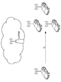
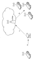
- V2X operation scenario A V2X operation scenario will be described. It is based on V2V communication. In the following description, when one vehicle becomes a pedestrian, it becomes V2P communication, and when it terminates in a facility or network, it becomes V2I / N communication.
- FIG. 1 shows a scenario in which vehicles communicate directly with each other without going through a base station (E-UTRAN).
- FIG. 2 shows a scenario in which vehicles communicate with each other via a base station.
- 3 and 4 show a scenario in which vehicles communicate with each other via a terminal (UE, here, a roadside wireless device (RSU)) and a base station.
- FIG. 5 shows a scenario in which vehicles communicate with each other via a terminal (UE, here, a roadside radio device (RSU)).
- UE terminal
- RSU roadside radio device
- V2X communication is different from D2D communication in terms of requirements and communication environment, existing D2D communication cannot be used as it is. Therefore, it is necessary to enhance to a form adapted to V2X communication. Differences in features between D2D communication and V2X communication are shown below.
- V2X communication is highly reliable and requires low-delay communication.
- V2X-specific traffic There is V2X-specific traffic.
- V2X has various links.
- Capacity is a bigger issue than D2D.
- Position information can always be obtained.
- V2X communication has many safety applications, and reliability is a very important index. Further, since the moving speed of the car is faster than that of the D2D walking use case, it is necessary to realize low-delay communication.
- Periodic traffic is communication that periodically notifies the surrounding vehicle of data, which is also a characteristic point of V2X.
- V vehicle
- I facility
- N network
- P pedestrian
- the IBE problem (4) and the HD problem (5) are related to the topology of the terminal and the RF performance.
- IBE will be described with reference to FIG.
- the positional relationship between the transmitting and receiving terminals always changes. If there is a receiving terminal in the vicinity of the transmitting terminal, the Emission from the transmitting side may affect the neighboring receiving terminal. Although orthogonality is maintained on the frequency axis, the influence of IBE becomes remarkable from the closeness of the distance between the transmitting and receiving terminals.
- FIG. 6 shows a state in which the transmitting terminal A gives IBE to the receiving terminal D.
- HD problem refers to a problem that the terminal cannot receive when it is transmitting. For this reason, it is necessary to take measures such as preparing an opportunity to receive a plurality of times, or not assigning transmissions of other users in a frame for transmitting data.
- the HD problem is not a problem specific to V2X, but is a major limitation in V2X communication that requires many transmissions.
- V2X communication has an extremely large number of accommodated terminals compared to D2D communication. Furthermore, since the automobile runs on the road, the terminal density inevitably increases locally. Therefore, in V2X communication, improvement of capacity is indispensable. It is necessary to eliminate unnecessary overhead as much as possible to realize efficient communication.
- the PC5 interface through which D2D communication and V2X communication are performed mainly includes a control channel section (PSCCH: Physical Sidelink Channel) and a data channel section (PSSCH: Physical Sideline Shared Channel).
- PSCCH Physical Sidelink Channel
- PSSCH Physical Sideline Shared Channel
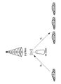
- the TDM scheme Since a PSCH resource instruction or the like is notified in the PSCCH, the TDM scheme has a problem that a delay from generation of a packet to transmission becomes large. On the other hand, there is an advantage that the complexity (complexity) of the terminal is good. In D2D, a TDM allocation method is adopted. On the other hand, in the FDM system, since the PSCCH is mapped in the frequency direction, the delay is improved. In addition, it is expected that problems of IBE and HD can be improved by transmitting SA (Scheduling Assignment) and Data in the same SF (subframe). Therefore, in V2X communication, establishment of a communication method using the FDM method is required.
- SA Service Assignment
- SPS Semi-Persistent Scheduling
- Mode 1 Centralized resource allocation
- Mode 2 Autonomous resource selection.
- the base station performs all resource allocation for the PC5 interface.
- the terminal side it is only necessary to perform transmission using resources instructed to the base station.
- the communication characteristics are good because resources are allocated orthogonally.
- the terminal autonomously selects a resource to be used for transmission from the resource pool notified from the base station.
- Mode 2 has an advantage that it can be operated not only in In-coverage in the network of the base station but also in Out-of-overage.
- the Solution can be roughly divided into two.
- One is energy sensing.
- energy sensing a resource is sensed for a certain period, and a communication resource is selected from relatively unused resources based on the sensing result. While simple, the power level is not so accurate. However, it is possible to sense a system other than LTE.
- Another method is SA decoding. This is a method of recognizing the location of a resource being used by decoding SA (control information) transmitted by another user. While the used resources can be discovered with high accuracy, there are disadvantages such that the SA resource itself cannot be sensed, and if the SA decoding fails, the used resource cannot be detected.
- Table 2 shows a list of explanations of enhancements so far. This is an example and describes typical enhancements, and various other methods are being considered.
- Sensing mode switching When there are one or more sensing modes, the UE does not know which sensing mode should be used in a given situation. As for energy sensing, blind sensing is used for the SA pool and the data pool, which is a sensing mode that uses power very much for a UE carried by a pedestrian.
- the UE sets the sensing mode by two methods.
- the first method is to determine which sensing mode the eNB should use.
- FIG. 11 is a flowchart illustrating a sensing mode determination method by the eNB, the transmission side UE, and the reception side UE.
- ENB determines the sensing mode and sensing parameters. Subsequently, the eNB generates a mapping table in which the relationship between the sensing mode, the sensing parameter, and the state is defined. Subsequently, the eNB determines a sensing mode and a sensing parameter, and notifies the UE on the transmission side of the sensing mode and the sensing parameter.
- the UE on the transmission side sets the sensing mode and sensing parameter notified from the eNB, performs sensing according to the sensing mode and sensing parameter, and transmits the packet.
- the receiving side UE receives the packet transmitted from the transmitting side UE.
- the second method is a method for determining which sensing mode the UE should use.
- FIG. 12 is a flowchart illustrating a sensing mode determination method by the eNB, the transmission side UE, and the reception side UE.
- ENB determines the sensing mode and sensing parameters. Subsequently, the eNB generates a mapping table in which the relationship between the sensing mode, the sensing parameter, and the state is defined. Subsequently, the eNB notifies the UE on the receiving side of the mapping table.
- the mapping table may be pre-configured in advance in the terminal.
- the UE on the receiving side determines the sensing mode and sensing parameter, performs sensing according to the sensing mode and sensing parameter, and transmits a packet.
- the receiving side UE receives the packet transmitted from the transmitting side UE.
- the mapping table is a table in which which sensing mode is used and which sensing parameter is used depending on the situation.
- Table 3 shows an example of the mapping table.
- “Sensing mode” is used for energy sensing, SA decoding, or a combination thereof. In addition to this, “Sensing mode” may be used in combination with data decoding, assistant sensing from the eNB, or the like. Data decoding is a method of decoding data of other terminals and confirming the resource usage status, and assistant sensing from the eNB is a method of sensing by receiving information on radio environment information from the eNB.
- “Condition” sends a periodic or event triggered message, for example, the UE has a low power requirement, has a safety requirement, has a low latency requirement, Have high or low priority, categories, types of sensing channels such as PSCCH, PSSCH, types of presence of other RATs (Radio Access Technologies), data traffic congestion, resource usage, terminal There can be a location.
- the UE has a low power requirement, has a safety requirement, has a low latency requirement, Have high or low priority, categories, types of sensing channels such as PSCCH, PSSCH, types of presence of other RATs (Radio Access Technologies), data traffic congestion, resource usage, terminal There can be a location.
- RATs Radio Access Technologies
- Sensing parameter may include, for example, parameters such as sensing interval, sensing start time, weight information, information on a limited sensing area for saving battery, and the like.
- the limited sensing area information may include sensing time interval and frequency band information, for example, information such as a sensing frequency region, such as bandwidth, resource pool, and subcarrier.
- the restricted sensing area information may also include, for example, sensing area definition, eg, block ID information.
- the block ID is an ID assigned to each partitioned pool.
- the information on the restricted sensing area may include information on a location where sensing is performed. The terminal performs the specified sensing at the specified position.
- the mapping table can be updated.
- the sensing mode can be changed depending on the given situation, and the sensing parameter can be changed depending on the given situation. Also, the sensing parameter can be changed according to a given sensing mode.
- ENB evaluates whether the current mapping is not the best choice. Also, the UE reports to the eNB that the current mapping is not the best choice. Thereby, the mapping table can be updated.
- the eNB notifies the UE of the mapping table or the sensing mode and sensing parameters, and for this notification, for example, SIB or DCI may be used. For example, the eNB broadcasts this information. For example, in a coexisting DSRC scenario, the eNB requests all UEs to select energy sensing. Further, for example, the eNB notifies the multicast information to a group of UEs and some UEs. Also, for example, the eNB notifies information to a unique UE by unicast.
- the mapping table can be transmitted at the timing of RRC connection setup or re-establishment, for example. Further, the mapping table can be transmitted, for example, at an initially set timing. Also, the mapping table can be transmitted at an updated timing, for example. Further, the mapping table can be transmitted, for example, at a timing when the UE transmits a request for the mapping table. Further, the mapping table can be transmitted periodically, for example, at a period defined by the UE.
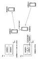
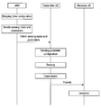
- centralized sensing is executed by two methods.
- the first method is a method in which the eNB or RSU determines one or more representatives that perform sensing.
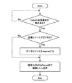
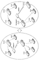
- FIG. 13 is a flowchart illustrating an operation example of an eNB or RSU, a node that is representatively sensing, and other UEs when performing sensing centralization.
- the eNB or RSU defines conditions representative of sensing, determines a node to be represented as a representative, and transmits a message indicating that it has been assigned as a representative to the determined node.
- the representative transmits an ACK or NACK to the message indicating that the representative has been assigned to the eNB or RSU.
- the eNB or the RSU itself can be a representative.
- the eNB or RSU may be set as a representative, or may be set as a representative from the Core Network side.
- the setting can be performed from the eNB side.
- the eNB or RSU When the eNB or RSU receives a reply from the representative, the eNB or RSU transmits information indicating that the representative UE has been assigned to the other UEs.
- the representative performs sensing by setting sensing.
- the representative transmits a sensing result to the UE that is not represented.
- ENB or RSU determines whether to release the representative and reassign the representative.
- the eNB or RSU sends a release message to the current representative.
- the representative transmits ACK or NACK for the release message to the eNB or RSU.
- the eNB or RSU transmits information indicating that the representative has been released to other UEs, and transmits a message indicating that the representative has been assigned to another node.
- the representative transmits an ACK or NACK to the message indicating that it has been assigned as a representative to the eNB or RSU.
- the eNB or RSU receives a reply from the representative, the eNB or RSU transmits information indicating that the representative is assigned to the other UEs.
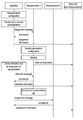
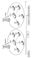
- the second method is a method in which the UE determines one or more representative UEs that perform sensing.
- FIG. 14 is a flowchart showing an operation example of an eNB or RSU, a node that is representatively sensing, and other UEs when performing sensing centralization.
- ENB or RSU defines conditions representative of sensing, and transmits representative setting information to the UE.
- the UE that has received the representative setting information from the eNB or the RSU determines a representative based on the information, and transmits a message indicating that the representative has been assigned to the node determined as the representative.
- the representative who has received the message indicating the assignment as the representative transmits ACK or NACK.
- the representative performs sensing by setting sensing.
- the representative transmits a sensing result to the UE that is not represented.
- the UE can also determine whether to release the representative and reassign the representative. When releasing the representative, the UE sends a release message to the current representative. The representative transmits an ACK or NACK for the release message to the UE.
- the UE transmits information indicating that the representative has been released to other UEs, and transmits a message indicating that the representative has been assigned to another node.
- the representative transmits an ACK or NACK to the message indicating that the representative has been assigned to the UE.
- the UE Upon receiving a reply from the representative, the UE transmits information indicating that the representative UE has been assigned to the other UEs.
- eNB may be a representative of sensing
- RSU may be a representative of sensing
- UE may be a representative of sensing.
- the eNB, RSU, or UE to determine the representative UE may be determined randomly from UEs in a predetermined area in a predetermined period, or may be determined based on a predetermined rule.
- the UE that is transmitting the synchronization signal may be the representative UE, and the UE ID, UE location, UE category, UE battery status, UE speed, UE mobility, UE The representative UE may be determined based on the status of the buffer.
- the representative setting information may include information such as a method for determining the representative, a start time and a period of the representative, and a sensing parameter.
- the sensing parameters may include parameters such as a sensing mode, a sensing start time, a sensing period, and a sensing target, for example.
- the sensing target can be LTE-V2X, DSRC, or the like. If the target is LTE-V2X, UE, a list of UEs to be sensed may be provided.
- the release of the representative may be performed, for example, when the current representative cannot sense.
- the UE in the eNB or RSU, when the sensing function is stopped, the UE is in an idle state, requested to suppress power consumption, and out of the current eNB coverage, from the responsibility of the current RSU This is the case when it comes off.
- Reassignment of the representative may be performed immediately after the representative is released, or may be performed when the timer value reaches the next allocation timing.
- the representative For ACK or NACK, the representative returns ACK when an allocation or release request is sent to the representative. If a NACK is returned or there is no response until the response deadline, a new representative can be assigned.
- the eNB monitors resource usage and sensing of all UEs in coverage. In this case, the eNB collects radio condition measurement reports from UEs in coverage.
- the RSU monitors resource usage and sensing of nearby UEs.
- the eNB determines a UE to be sensed representatively at random or in a predetermined method.
- the predetermined method may be, for example, a method of selecting a terminal having a high SA reception capability (such as a terminal equipped with an advanced receiver), and selecting a UE that does not mind power consumption even when energy sensing is used. The method is fine.
- the RSU may determine a UE to be sensed representatively at random or by a predetermined method.
- the UE determines a UE that is transmitting a synchronization signal randomly or based on the ID of the UE.
- the representative UE can be released. For example, when the UE becomes incapable of sensing, for example, when the UE status changes from Connected to idle, when the UE wants to reduce power consumption, when the UE is out of the current eNB coverage, the UE is responsible for the current RSU. If you are out of the range, there may be.
- the representative UE can also be released when the sensing period timer is set and the sensing period ends. At the end of the sensing period, the eNB or RSU may decide to release, and the UE may sense one after another.
- a new UE may be selected at random, or may be selected by a predetermined method. Further, the reallocation may be performed immediately after the release or may be performed after a predetermined time has elapsed.
- Sensing + LBT Listen Before Talk
- Sensing + LBT Listen Before Talk
- LBT is a method adopted in the WiFi system, but it is difficult to handle specific traffic, and it is difficult to apply it as it is in V2X communication that can receive support from a base station. Therefore, LBT enhancement is required for LTE V2X communication.
- the sensing method here is not limited to energy sensing, and SA decoding, data decoding method, or the like may be used.
- V2X communication there are a periodical traffic where the latency requirement is not so severe and an event trigger traffic where the latency requirement is severe.
- the latency of the LBT back-off time becomes latency, and the communication request may not be satisfied in some cases.
- the sensing threshold may be set separately for Type 1 and Type 2.
- the threshold may be set separately for each channel such as PSCCH and PSSCH.
- a switching method of the LBT method is proposed according to the traffic type to be transmitted.
- FIG. 15 is a flowchart showing a switching method of the LBT method. This indicates that if the traffic to be transmitted is traffic with a severe latency requirement, for example, if the event trigger traffic is sent, it is sent with Type 2, and if not, it is sent with Type 1.
- the LBT method may be switched according to the resource usage status (traffic congestion status). If the available resources are tight after sensing, the probability of selecting the same resource as the neighboring terminal is increased. In order to avoid this, the terminal switches the LBT method according to the degree of resource congestion. For example, when sensing is performed and a resource amount that can be selected is equal to or less than a certain threshold, the terminal determines that a resource selection cover occurs with another terminal and operates to avoid the cover by selecting the LBT method. be able to.
- a terminal category As information used for switching the LBT, a terminal category, a terminal ID, traffic priority information, a terminal speed, and the like may be used in addition to the traffic type and the resource usage status. May be switched.
- the LBT type switching method notifies an arbitrary LBT method from the base station. This may be notified for each UE or for each cell.
- the base station may provide an LBT method and a mapping table of information used for switching to the terminal, and the terminal may select the LBT type according to the information used for switching.
- An LBT type switching method may be preset in the terminal.
- V2X communication Introduction of two-step sensing, a case where operation is performed while performing co-existence with a DSRC system (802.11p communication) is assumed. In this case, the LTE V2X communication needs to detect the DSRC system and perform an operation so as not to cause interference. At the same time, it is necessary to avoid packet collision with other users even in LTE V2X communication.
- DSRC_LBT for DSRC system detection is introduced.
- DSRC_LBT may be Type 1 or Type 2, but Type 1 is preferable.
- LTE_V2X_LBT for avoiding Mode2 communication packet collision in the LTE V2X system is introduced.
- LTE_V2X_LBT may be Type 1 or Type 2, but Type 2 is preferable.
- LTE_V2X_LBT In addition to LTE_V2X_LBT, other sensing methods such as SA decoding may be used.
- FIG. 16 is a flowchart showing the flow of two-step sensing at the terminal.
- the terminal performs DSRC_LBT and performs LTE_V2X_LBT after determining that the channel state is IDLE.
- LTE_V2X_LBT When the channel state is determined to be IDLE in LTE_V2X_LBT, a signal is transmitted.
- the terminal may change the area for sensing with DSRC_LBT and LTE_V2X_LBT. Also, the terminal may change the region in the frequency direction, may change the region in the time direction, or may change the region in both the frequency direction and the time direction.
- the sensing area may be notified in advance from the base station, or may be set in advance in the terminal.
- a back-off timer is set from the base station to the terminal.
- the notification method from the base station to the terminal may be notified by RRC, may be notified by DCI, may be notified by SIB, may be notified by signaling, or may be notified by other methods. Also good.
- the value of the backoff timer may be a backoff timer in the time direction, a backoff timer in the frequency direction, or a backoff timer in both the time direction and the frequency direction.
- the band may be divided into a plurality of subcarriers, may be divided by the number of subcarriers used for its own transmission, or may be uniquely divided by the system.
- the value of the back-off timer may be the sum of the back-off timers for both time and frequency. Further, a valid period of the back-off timer may be set from the base station to the terminal. Further, the back-off timer may be set across a plurality of scheduling periods.
- the back-off timer table When the back-off timer table is provided from the base station to the terminal, information such as the back-off timer value, the time-direction back-off timer, the frequency-direction back-off timer, and the time-frequency back-off timer are added. May be.
- FIG. 17 is a flowchart showing an example of backoff operation.
- the backoff may be set in the time direction or may be set in the frequency direction. Moreover, you may set to both time and a frequency.
- the terminal senses the specified time and frequency domain, and if Occupation is detected, it determines whether there is still a sensing area in the frequency direction, and if there is none, it slides in the frequency direction, otherwise it slides in the time direction. The frequency direction is reset. If the terminal does not detect Occupation, the terminal performs back-off subtraction described later.
- the back-off may be configured by any of Subframe, Subcarrier, and SA period units, or may be configured by a combination thereof.
- the terminal When the terminal is notified of a specific back-off timer, the terminal sets the back-off timer. When the back-off timer is set with a width, the terminal randomly selects from the width.
- the terminal selects the back-off timer according to the associated parameter.
- the back-off timer is set with a width, a random selection is made from the width.
- the terminal performs back-off value subtraction according to the sensing result.
- the terminal can subtract in the time direction and the frequency direction, respectively.
- backoff is set for each of time and frequency
- the terminal performs subtraction for each. If it is a common back-off, the terminal subtracts one when detecting one non-occupation regardless of time and frequency.
- FIG. 18 is a flowchart showing a sensing area setting method.
- Examples of the time and frequency sliding method include a method of sliding first in the time direction and then sliding in the frequency direction.
- Sensing + LBT transmission is performed after acquisition of the transmission right.
- SA pool and data pool are separated in terms of time, so it is necessary to newly set conditions for acquiring transmission rights. For example, even if the SA resource transmission right is acquired, transmission is not possible unless resources in the data area are secured. The reverse is also true. In this way, it is necessary to newly define the conditions for acquiring the transmission right.
- three methods are shown.
- a method for acquiring SA and data transmission rights when SA transmission resources can be secured.
- a transmission terminal senses only the SA area and obtains SA transmission rights, the SA and data transmission rights are obtained. It is a method to acquire. Since sensing of the data part is not performed, collision of the data part may occur. Since at least SA is sensing, it is better than doing nothing.
- the transmission right acquisition condition is when SA_LBT is OK. If the remaining SA resource is equal to or greater than a certain value, the SA resource is randomly selected from the remaining SA pool, and the data resource is randomly selected from the data pool, and then transmitted.
- the transmission is postponed until the next SA period. Randomly select the SA resource from the SA resource pool based on the SA_LBT result randomly or based on the SA_LBT result, and then send the data resource selected at random from the data pool.
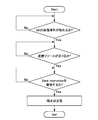
- FIG. 19 is a flowchart showing a method for determining whether or not the transmission right can be obtained only by the SA.
- N is a counter, and N is decremented by 1 when the SA channel is idle.
- SA_LBT 0.
- the terminal determines whether the corresponding SA period has sufficient SA resources by comparing with a usable subframe SF available which is a parameter set in advance by the base station.
- the terminal randomly selects an SA resource from the SA resource pool. If there are enough SA resources, the terminal postpones transmission until the next SA period. Randomly select the SA resource from the SA resource pool based on the SA_LBT result randomly or based on the SA_LBT result, and then send the data resource selected at random from the data pool.
- the terminal may subtract a certain amount of the back-off value in order to increase the priority for acquiring the transmission opportunity when transmitting in the following SA period.
- the transmission right acquisition condition is when Data_LBT is OK. If the remaining data resources in the corresponding SA period exceed a certain value, the data resources are reserved from the remaining.
- the terminal randomly selects an SA resource from the SA resource pool for the next SA period, selects a reserved data resource from the data pool, and transmits it.
- the SA resource is randomly selected from the SA resource pool as the next SA period, and is transmitted when the data resource is selected randomly from the data pool or based on the result of DATA_LBT.
- FIG. 20 is a flowchart showing an operation example when the SA and the data transmission right are acquired when the data transmission resource can be secured.
- DATA_LBT N and sensing is started.
- N is a counter, and N is decremented by 1 when the SA channel is idle.
- the terminal determines whether or not there is sufficient data resource in the corresponding SA period by comparing it with an available subframe SF available which is a parameter preset by the base station.
- the terminal randomly selects an SA resource from the SA resource pool for the next SA period, selects a reserved data resource from the data pool, and transmits it.
- the SA resource is randomly selected from the SA resource pool as the next SA period, and is transmitted when the data resource is selected randomly from the data pool or based on the result of DATA_LBT.
- a method of acquiring SA and data transmission rights when both SA and data transmission resources can be secured.
- the transmitting terminal performs sensing of both the SA area and the data area. Only SA applies LBT, and data introduces a new reservation. Since both SA and data are sensed, the probability of collision is low compared to the above two methods.
- the transmission right acquisition condition is when SA_LBT is OK and the resource in the Data area is “Reserved”. If the remaining SA resources are below a certain value, the transmission is postponed until the next SA period.
- FIG. 21 is a flowchart showing an operation example in the case where both the SA and data transmission resources are secured and the SA and data transmission rights are acquired.
- the data pool performs sensing without LBT and reserves resources to be used. It is determined whether or not to use the reserved data resource according to the SA_LBT result.
- the securing of the data resource reserves the resource to be used using sensing without LBT.
- the terminal When the terminal performs SA_LBT and acquires the transmission right, the terminal refers to the reserved data resource of the previous SA period and selects the resource of the current SA period. If the remaining SA resources are below a certain value, the terminal postpones transmission until the next SA period.
- Mode 1 and Mode 2 sensing The UE should be in eNB coverage.
- the eNB sets up a resource pool and indicates resource allocation for all UEs.
- FIG. 24 is an explanatory diagram showing an example of mode 1 resource allocation.
- Mode 2 The UE may be present or out of coverage of the eNB. If out of coverage, the resource pool should be pre-configured. The UE randomly selects a resource from the resource pool.
- FIG. 25 is an explanatory diagram showing an example of resource allocation in mode 2.
- the UE may have a limited time interval for sensing.
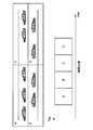
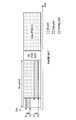
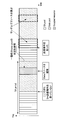
- FIG. 26 is an explanatory diagram illustrating an example in which the sensing time interval is limited in TDM.
- the UE is informed of the time interval for sensing as ⁇ (SF1, SF2), (SF3, SF4), (SF4, SF5) ⁇ in FIG.
- FIG. 27 is an explanatory diagram illustrating an example in which the sensing frequency band is limited in TDM.
- the UE is informed of a frequency band for sensing, for example, SA ⁇ (F1, F2) ⁇ , data ⁇ (F3, F4) ⁇ in FIG.
- FIG. 28 is an explanatory diagram illustrating an example in which both the sensing time interval and the frequency band are limited in TDM.
- the UE performs sensing of ⁇ SF1, SF2), (SF3, SF4), (SF4, SF5) ⁇ , SA ⁇ (F1, F2) ⁇ , data ⁇ (F3, F4) ⁇ in FIG. Be informed of the time interval and frequency band for.
- FIG. 29 is an explanatory diagram illustrating an example in which a sensing block is limited in TDM. The UE is informed of a block ID for sensing in block units, for example, ⁇ s4, d2, d5 ⁇ in FIG.
- FIG. 30 is an explanatory diagram illustrating an example in which the sensing time interval is limited in the FDM.
- the UE is informed of the time interval for sensing as ⁇ (SF1, SF2), (SF3, SF4), (SF4, SF5) ⁇ in FIG.
- FIG. 31 is an explanatory diagram illustrating an example in which the sensing frequency band is limited in the FDM.
- the UE is informed of the frequency band for sensing, for example, ⁇ (F1, F2) ⁇ , ⁇ (F3, F4) ⁇ in FIG.
- FIG. 32 is an explanatory diagram showing an example in which both the sensing time interval and the frequency band are limited in FDM.
- the UE is, for example, SA ⁇ (SF1, SF2) ⁇ , ⁇ (SF3, SF4) ⁇ , data ⁇ (SF4, SF5) ⁇ , ⁇ (F1, F2), (F3, F4) ⁇ in FIG. You are informed of the time interval and frequency band for sensing.
- FIG. 33 is an explanatory diagram showing an example in which the sensing block is limited in the FDM.
- the UE is informed of a block ID for sensing in block units, for example, ⁇ s4, d4 ⁇ in FIG.
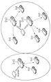
- FIG. 34 is an explanatory diagram showing how the eNB performs sensing.
- FIG. 35 is an explanatory diagram showing how the RSU performs sensing.
- FIG. 36 is an explanatory diagram showing a state where a typical UE performs sensing.
- FIG. 36 illustrates an example in which the eNB assigns one or more UEs as UEs that perform sensing.
- FIG. 37 is an explanatory diagram showing how a typical UE performs sensing.
- FIG. 37 shows an example when the RSU assigns one or more UEs as UEs that perform sensing.
- FIG. 38 is an explanatory diagram showing how a typical UE performs sensing.
- FIG. 38 shows an example in which the UE determines a representative UE by itself using, for example, UEid.
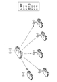
- FIG. 39 is an explanatory diagram illustrating a state where a representative UE is released when the UE state changes from connected to idle.
- a representative UE may be released when away from the current eNB or RSU.
- FIG. 40 is an explanatory diagram illustrating an example in which a typical UE is released when the user moves away from the current eNB.
- FIG. 41 is an explanatory diagram showing an example in which a typical UE is released when the user moves away from the current RSU.
- FIG. 42 is an explanatory diagram illustrating an example of a new typical UE assignment using a timer.
- FIG. 43 is an explanatory diagram illustrating an example in which a typical UE performs sensing in order using a predetermined timer.
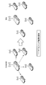
- the transmission terminal sets the counter N to 5.
- the terminal starts sensing from the next subframe SF1.
- the terminal selects a resource and transmits a packet in the next subframe SF8.
- the transmission terminal sets the counter N to 5. After waiting for 5 subframes, the terminal selects a resource in the next subframe and transmits a packet.
- FIG. 44 is an explanatory diagram showing an enhanced LBT.
- the UE randomly selects an SA resource from the remaining SA pool and data pool in the current SA period.
- FIG. 45 is an explanatory diagram showing an enhanced LBT.
- the UE randomly selects SA resources and data resources from the SA pool and data pool in the next SA period.
- FIG. 46 is an explanatory diagram showing the enhanced LBT.
- the UE selects an SA resource based on the SA_LBT result from among the SA pool and data pool in the next SA period, and also randomly selects a data resource.
- the subframe offset is set to 2.
- the counter N is 0 and a transmission right is obtained and the number of remaining subframes is 3, which is larger than the subframe offset, is shown.
- FIG. 47 is an explanatory diagram showing the enhanced LBT. In this case, the UE randomly selects an SA resource from the SA pool in the next SA period, and selects a data resource from the reserved data pool.
- FIG. 48 is an explanatory diagram showing the enhanced LBT.
- the UE randomly selects an SA resource and a data resource from the SA pool and data pool in the next SA period.
- FIG. 49 is an explanatory diagram showing the enhanced LBT.
- the UE selects an SA resource from the SA pool in the next SA period, and selects an SA resource from the DATA_LBT result in the data pool.
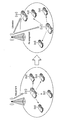
- FIG. 50 is an explanatory diagram showing the enhanced LBT. As a first example, a case is shown in which the SA transmission right is taken, but data resources are not secured. In this case, the UE reserves the data resource with the current SA period, and randomly selects the data resource from the SA pool and the data pool in the next SA period.
- FIG. 51 is an explanatory diagram showing the enhanced LBT.
- a case is shown in which data resources are secured but no SA transmission right is taken.
- the UE refers to the status of the previous SA period, and randomly selects an SA resource from the current SA pool and the reserved data pool.
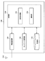
- FIG. 52 is a block diagram illustrating an exemplary configuration of the base station 100 according to the embodiment of the present disclosure.
- the base station 100 includes an antenna unit 110, a wireless communication unit 120, a network communication unit 130, a storage unit 140, and a processing unit 150.
- Antenna unit 110 The antenna unit 110 radiates a signal output from the wireless communication unit 120 to the space as a radio wave. Further, the antenna unit 110 converts radio waves in space into a signal and outputs the signal to the wireless communication unit 120.
- the wireless communication unit 120 transmits and receives signals.
- the radio communication unit 120 transmits a downlink signal to the terminal device and receives an uplink signal from the terminal device.
- the network communication unit 130 transmits and receives information.
- the network communication unit 130 transmits information to other nodes and receives information from other nodes.
- the other nodes include other base stations and core network nodes.
- Storage unit 140 The storage unit 140 temporarily or permanently stores a program for operating the base station 100 and various data.
- Processing unit 150 provides various functions of the base station 100.
- the processing unit 150 includes a transmission processing unit 151 and a notification unit 153.
- the processing unit 150 may further include other components other than these components. That is, the processing unit 150 can perform operations other than the operations of these components.
- the transmission processing unit 151 executes processing related to data transmission to the terminal device 200.
- the transmission processing unit 151 performs the overall processing of the base station (eNB) described above.
- the notification unit 153 executes processing related to notification of information to the terminal device 200.
- the notification unit 153 performs overall notification processing for the terminal device by the base station (eNB) described above.
- FIG. 53 is a block diagram illustrating an exemplary configuration of the terminal device 200 according to an embodiment of the present disclosure.
- the terminal device 200 includes an antenna unit 210, a wireless communication unit 220, a storage unit 230, and a processing unit 240.
- Antenna unit 210 The antenna unit 210 radiates the signal output from the wireless communication unit 220 to the space as a radio wave. Further, the antenna unit 210 converts a radio wave in the space into a signal and outputs the signal to the wireless communication unit 220.
- the wireless communication unit 220 transmits and receives signals.
- the radio communication unit 220 receives a downlink signal from the base station and transmits an uplink signal to the base station.
- Storage unit 230 The storage unit 230 temporarily or permanently stores a program for operating the terminal device 200 and various data.
- the processing unit 240 provides various functions of the terminal device 200.
- the processing unit 240 includes an acquisition unit 241 and a reception processing unit 243.
- the processing unit 240 may further include other components other than these components. That is, the processing unit 240 can perform operations other than the operations of these components.
- the acquisition unit 241 executes processing related to acquisition of data transmitted from the base station 100.
- the reception processing unit 243 executes processing related to reception of data acquired by the acquisition unit 241.
- the reception processing unit 243 executes the overall processing of the terminal device described above.
- the base station 100 may be realized as any type of eNB (evolved Node B) such as a macro eNB or a small eNB.
- the small eNB may be an eNB that covers a cell smaller than a macro cell, such as a pico eNB, a micro eNB, or a home (femto) eNB.
- the base station 100 may be realized as another type of base station such as a NodeB or a BTS (Base Transceiver Station).
- Base station 100 may include a main body (also referred to as a base station apparatus) that controls radio communication, and one or more RRHs (Remote Radio Heads) that are arranged at locations different from the main body. Further, various types of terminals described later may operate as the base station 100 by temporarily or semi-permanently executing the base station function.
- a main body also referred to as a base station apparatus
- RRHs Remote Radio Heads
- the terminal device 200 is a smartphone, a tablet PC (Personal Computer), a notebook PC, a portable game terminal, a mobile terminal such as a portable / dongle type mobile router or a digital camera, or an in-vehicle terminal such as a car navigation device. It may be realized as.
- the terminal device 200 may be realized as a terminal (also referred to as an MTC (Machine Type Communication) terminal) that performs M2M (Machine To Machine) communication.
- the terminal device 200 may be a wireless communication module (for example, an integrated circuit module configured by one die) mounted on these terminals.
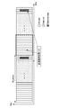
- FIG. 54 is a block diagram illustrating a first example of a schematic configuration of an eNB to which the technology according to the present disclosure may be applied.
- the eNB 800 includes one or more antennas 810 and a base station device 820. Each antenna 810 and the base station apparatus 820 can be connected to each other via an RF cable.
- Each of the antennas 810 has a single or a plurality of antenna elements (for example, a plurality of antenna elements constituting a MIMO antenna), and is used for transmission and reception of radio signals by the base station apparatus 820.
- the eNB 800 includes a plurality of antennas 810 as illustrated in FIG. 54, and the plurality of antennas 810 may respectively correspond to a plurality of frequency bands used by the eNB 800, for example.
- 54 illustrates an example in which the eNB 800 includes a plurality of antennas 810, but the eNB 800 may include a single antenna 810.
- the base station apparatus 820 includes a controller 821, a memory 822, a network interface 823, and a wireless communication interface 825.
- the controller 821 may be a CPU or a DSP, for example, and operates various functions of the upper layer of the base station apparatus 820. For example, the controller 821 generates a data packet from the data in the signal processed by the wireless communication interface 825, and transfers the generated packet via the network interface 823. The controller 821 may generate a bundled packet by bundling data from a plurality of baseband processors, and may transfer the generated bundled packet. In addition, the controller 821 is a logic that executes control such as radio resource control, radio bearer control, mobility management, inflow control, or scheduling. May have a typical function. Moreover, the said control may be performed in cooperation with a surrounding eNB or a core network node.
- the memory 822 includes RAM and ROM, and stores programs executed by the controller 821 and various control data (for example, terminal list, transmission power data, scheduling data, and the like).
- the network interface 823 is a communication interface for connecting the base station device 820 to the core network 824.
- the controller 821 may communicate with the core network node or other eNB via the network interface 823.
- the eNB 800 and the core network node or another eNB may be connected to each other by a logical interface (for example, an S1 interface or an X2 interface).
- the network interface 823 may be a wired communication interface or a wireless communication interface for wireless backhaul.
- the network interface 823 may use a frequency band higher than the frequency band used by the wireless communication interface 825 for wireless communication.
- the wireless communication interface 825 supports any cellular communication scheme such as LTE (Long Term Evolution) or LTE-Advanced, and provides a wireless connection to terminals located in the cell of the eNB 800 via the antenna 810.
- the wireless communication interface 825 may typically include a baseband (BB) processor 826, an RF circuit 827, and the like.
- the BB processor 826 may perform, for example, encoding / decoding, modulation / demodulation, and multiplexing / demultiplexing, and each layer (for example, L1, MAC (Medium Access Control), RLC (Radio Link Control), and PDCP).
- Various signal processing of Packet Data Convergence Protocol
- Packet Data Convergence Protocol is executed.
- the BB processor 826 may have some or all of the logical functions described above instead of the controller 821.
- the BB processor 826 may be a module that includes a memory that stores a communication control program, a processor that executes the program, and related circuits. The function of the BB processor 826 may be changed by updating the program. Good.
- the module may be a card or a blade inserted into a slot of the base station apparatus 820, or a chip mounted on the card or the blade.
- the RF circuit 827 may include a mixer, a filter, an amplifier, and the like, and transmits and receives a radio signal via the antenna 810.
- the wireless communication interface 825 includes a plurality of BB processors 826 as shown in FIG. 54, and the plurality of BB processors 826 may respectively correspond to a plurality of frequency bands used by the eNB 800, for example. Further, the wireless communication interface 825 includes a plurality of RF circuits 827 as shown in FIG. 54, and the plurality of RF circuits 827 may respectively correspond to a plurality of antenna elements, for example. 54 illustrates an example in which the wireless communication interface 825 includes a plurality of BB processors 826 and a plurality of RF circuits 827, the wireless communication interface 825 includes a single BB processor 826 or a single RF circuit 827. But you can.
- the eNB 800 includes a module including a part (for example, the BB processor 826) or all of the wireless communication interface 825 and / or the controller 821, and the one or more components are mounted in the module. Good.
- the module stores a program for causing the processor to function as the one or more components (in other words, a program for causing the processor to execute the operation of the one or more components). The program may be executed.
- a program for causing a processor to function as the one or more components is installed in the eNB 800, and the radio communication interface 825 (eg, the BB processor 826) and / or the controller 821 executes the program.
- the eNB 800, the base station apparatus 820, or the module may be provided as an apparatus including the one or more components, and a program for causing a processor to function as the one or more components is provided. May be.
- a readable recording medium in which the program is recorded may be provided.
- the radio communication unit 120 described with reference to FIG. 52 in the eNB 800 illustrated in FIG. 54 may be implemented in the radio communication interface 825 (for example, the RF circuit 827). Further, the antenna unit 110 may be mounted on the antenna 810.
- the network communication unit 130 may be implemented in the controller 821 and / or the network interface 823.
- the storage unit 140 may be implemented in the memory 822.
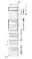
- FIG. 55 is a block diagram illustrating a second example of a schematic configuration of an eNB to which the technology according to the present disclosure may be applied.
- the eNB 830 includes one or more antennas 840, a base station apparatus 850, and an RRH 860. Each antenna 840 and RRH 860 may be connected to each other via an RF cable. Base station apparatus 850 and RRH 860 can be connected to each other via a high-speed line such as an optical fiber cable.
- Each of the antennas 840 has a single or a plurality of antenna elements (for example, a plurality of antenna elements constituting a MIMO antenna), and is used for transmission / reception of radio signals by the RRH 860.
- the eNB 830 includes a plurality of antennas 840 as illustrated in FIG. 55, and the plurality of antennas 840 may respectively correspond to a plurality of frequency bands used by the eNB 830, for example. 55 shows an example in which the eNB 830 has a plurality of antennas 840, but the eNB 830 may have a single antenna 840.
- the base station device 850 includes a controller 851, a memory 852, a network interface 853, a wireless communication interface 855, and a connection interface 857.
- the controller 851, the memory 852, and the network interface 853 are the same as the controller 821, the memory 822, and the network interface 823 described with reference to FIG.
- the wireless communication interface 855 supports a cellular communication method such as LTE or LTE-Advanced, and provides a wireless connection to a terminal located in a sector corresponding to the RRH 860 via the RRH 860 and the antenna 840.
- the wireless communication interface 855 may typically include a BB processor 856 and the like.
- the BB processor 856 is the same as the BB processor 826 described with reference to FIG. 54 except that the BB processor 856 is connected to the RF circuit 864 of the RRH 860 via the connection interface 857.
- the wireless communication interface 855 includes a plurality of BB processors 856 as illustrated in FIG.
- FIG. 55 shows an example in which the wireless communication interface 855 includes a plurality of BB processors 856, but the wireless communication interface 855 may include a single BB processor 856.
- connection interface 857 is an interface for connecting the base station device 850 (wireless communication interface 855) to the RRH 860.
- the connection interface 857 may be a communication module for communication on the high-speed line that connects the base station apparatus 850 (wireless communication interface 855) and the RRH 860.
- the RRH 860 includes a connection interface 861 and a wireless communication interface 863.
- connection interface 861 is an interface for connecting the RRH 860 (wireless communication interface 863) to the base station device 850.
- the connection interface 861 may be a communication module for communication on the high-speed line.
- the wireless communication interface 863 transmits and receives wireless signals via the antenna 840.
- the wireless communication interface 863 may typically include an RF circuit 864 and the like.
- the RF circuit 864 may include a mixer, a filter, an amplifier, and the like, and transmits and receives wireless signals via the antenna 840.
- the wireless communication interface 863 includes a plurality of RF circuits 864 as shown in FIG. 55, and the plurality of RF circuits 864 may correspond to, for example, a plurality of antenna elements, respectively.
- FIG. 55 shows an example in which the wireless communication interface 863 includes a plurality of RF circuits 864, but the wireless communication interface 863 may include a single RF circuit 864.
- one or more components included in the processing unit 150 described with reference to FIG. 52 include the wireless communication interface 855 and / or the wireless The communication interface 863 may be implemented. Alternatively, at least some of these components may be implemented in the controller 851.
- the eNB 830 includes a module including a part (for example, the BB processor 856) or the whole of the wireless communication interface 855 and / or the controller 851, and the one or more components are mounted in the module. Good.
- the module stores a program for causing the processor to function as the one or more components (in other words, a program for causing the processor to execute the operation of the one or more components).
- the program may be executed.
- a program for causing a processor to function as the one or more components is installed in the eNB 830, and the wireless communication interface 855 (eg, the BB processor 856) and / or the controller 851 executes the program.
- the eNB 830, the base station apparatus 850, or the module may be provided as an apparatus including the one or more components, and a program for causing a processor to function as the one or more components is provided. May be.
- a readable recording medium in which the program is recorded may be provided.
- the radio communication unit 120 described with reference to FIG. 52 may be implemented in the radio communication interface 863 (for example, the RF circuit 864).
- the antenna unit 110 may be mounted on the antenna 840.
- the network communication unit 130 may be implemented in the controller 851 and / or the network interface 853.
- the storage unit 140 may be mounted in the memory 852.
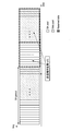
- FIG. 56 is a block diagram illustrating an example of a schematic configuration of a smartphone 900 to which the technology according to the present disclosure may be applied.
- the smartphone 900 includes a processor 901, a memory 902, a storage 903, an external connection interface 904, a camera 906, a sensor 907, a microphone 908, an input device 909, a display device 910, a speaker 911, a wireless communication interface 912, one or more antenna switches 915.
- One or more antennas 916, a bus 917, a battery 918 and an auxiliary controller 919 are provided.
- the processor 901 may be, for example, a CPU or a SoC (System on Chip), and controls the functions of the application layer and other layers of the smartphone 900.
- the memory 902 includes a RAM and a ROM, and stores programs executed by the processor 901 and data.
- the storage 903 can include a storage medium such as a semiconductor memory or a hard disk.
- the external connection interface 904 is an interface for connecting an external device such as a memory card or a USB (Universal Serial Bus) device to the smartphone 900.
- the camera 906 includes, for example, an image sensor such as a CCD (Charge Coupled Device) or a CMOS (Complementary Metal Oxide Semiconductor), and generates a captured image.
- the sensor 907 may include a sensor group such as a positioning sensor, a gyro sensor, a geomagnetic sensor, and an acceleration sensor.
- the microphone 908 converts sound input to the smartphone 900 into an audio signal.
- the input device 909 includes, for example, a touch sensor that detects a touch on the screen of the display device 910, a keypad, a keyboard, a button, or a switch, and receives an operation or information input from a user.
- the display device 910 has a screen such as a liquid crystal display (LCD) or an organic light emitting diode (OLED) display, and displays an output image of the smartphone 900.
- the speaker 911 converts an audio signal output from the smartphone 900 into audio.
- the wireless communication interface 912 supports any cellular communication method such as LTE or LTE-Advanced, and performs wireless communication.
- the wireless communication interface 912 may typically include a BB processor 913, an RF circuit 914, and the like.
- the BB processor 913 may perform, for example, encoding / decoding, modulation / demodulation, and multiplexing / demultiplexing, and performs various signal processing for wireless communication.
- the RF circuit 914 may include a mixer, a filter, an amplifier, and the like, and transmits and receives radio signals via the antenna 916.
- the wireless communication interface 912 may be a one-chip module in which the BB processor 913 and the RF circuit 914 are integrated.
- the wireless communication interface 912 may include a plurality of BB processors 913 and a plurality of RF circuits 914 as shown in FIG. 56 shows an example in which the wireless communication interface 912 includes a plurality of BB processors 913 and a plurality of RF circuits 914, the wireless communication interface 912 includes a single BB processor 913 or a single RF circuit 914. But you can.
- the wireless communication interface 912 may support other types of wireless communication methods such as a short-range wireless communication method, a proximity wireless communication method, or a wireless LAN (Local Area Network) method in addition to the cellular communication method.
- a BB processor 913 and an RF circuit 914 for each wireless communication method may be included.
- Each of the antenna switches 915 switches the connection destination of the antenna 916 among a plurality of circuits (for example, circuits for different wireless communication systems) included in the wireless communication interface 912.
- Each of the antennas 916 includes a single or a plurality of antenna elements (for example, a plurality of antenna elements constituting a MIMO antenna), and is used for transmission / reception of a radio signal by the radio communication interface 912.
- the smartphone 900 may include a plurality of antennas 916 as illustrated in FIG. Note that FIG. 56 illustrates an example in which the smartphone 900 includes a plurality of antennas 916, but the smartphone 900 may include a single antenna 916.
- the smartphone 900 may include an antenna 916 for each wireless communication method.
- the antenna switch 915 may be omitted from the configuration of the smartphone 900.
- the bus 917 connects the processor 901, the memory 902, the storage 903, the external connection interface 904, the camera 906, the sensor 907, the microphone 908, the input device 909, the display device 910, the speaker 911, the wireless communication interface 912, and the auxiliary controller 919 to each other.
- the battery 918 supplies power to each block of the smartphone 900 shown in FIG. 56 via a power supply line partially shown by a broken line in the drawing.
- the auxiliary controller 919 operates the minimum necessary functions of the smartphone 900 in the sleep mode.
- the smartphone 900 includes a module including a part (for example, the BB processor 913) or the whole of the wireless communication interface 912, the processor 901, and / or the auxiliary controller 919, and the one or more components in the module. May be implemented.
- the module stores a program for causing the processor to function as the one or more components (in other words, a program for causing the processor to execute the operation of the one or more components). The program may be executed.
- a program for causing a processor to function as the one or more components is installed in the smartphone 900, and the wireless communication interface 912 (eg, the BB processor 913), the processor 901, and / or the auxiliary controller 919 is The program may be executed.
- the smartphone 900 or the module may be provided as a device including the one or more components, and a program for causing a processor to function as the one or more components may be provided.
- a readable recording medium in which the program is recorded may be provided.
- the wireless communication unit 220 described with reference to FIG. 53 may be implemented in the wireless communication interface 912 (for example, the RF circuit 914).
- the antenna unit 210 may be mounted on the antenna 916.
- the storage unit 230 may be mounted in the memory 902.
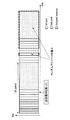
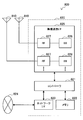
- FIG. 57 is a block diagram illustrating an example of a schematic configuration of a car navigation device 920 to which the technology according to the present disclosure can be applied.
- the car navigation device 920 includes a processor 921, a memory 922, a GPS (Global Positioning System) module 924, a sensor 925, a data interface 926, a content player 927, a storage medium interface 928, an input device 929, a display device 930, a speaker 931, and wireless communication.
- the interface 933 includes one or more antenna switches 936, one or more antennas 937, and a battery 938.
- the processor 921 may be a CPU or SoC, for example, and controls the navigation function and other functions of the car navigation device 920.
- the memory 922 includes RAM and ROM, and stores programs and data executed by the processor 921.
- the GPS module 924 measures the position (for example, latitude, longitude, and altitude) of the car navigation device 920 using GPS signals received from GPS satellites.
- the sensor 925 may include a sensor group such as a gyro sensor, a geomagnetic sensor, and an atmospheric pressure sensor.
- the data interface 926 is connected to the in-vehicle network 941 through a terminal (not shown), for example, and acquires data generated on the vehicle side such as vehicle speed data.
- the content player 927 reproduces content stored in a storage medium (for example, CD or DVD) inserted into the storage medium interface 928.
- the input device 929 includes, for example, a touch sensor, a button, or a switch that detects a touch on the screen of the display device 930, and receives an operation or information input from the user.
- the display device 930 has a screen such as an LCD or an OLED display, and displays a navigation function or an image of content to be reproduced.
- the speaker 931 outputs the navigation function or the audio of the content to be played back.
- the wireless communication interface 933 supports any cellular communication method such as LTE or LTE-Advanced, and performs wireless communication.
- the wireless communication interface 933 may typically include a BB processor 934, an RF circuit 935, and the like.
- the BB processor 934 may perform, for example, encoding / decoding, modulation / demodulation, and multiplexing / demultiplexing, and performs various signal processing for wireless communication.
- the RF circuit 935 may include a mixer, a filter, an amplifier, and the like, and transmits and receives a radio signal via the antenna 937.
- the wireless communication interface 933 may be a one-chip module in which the BB processor 934 and the RF circuit 935 are integrated.
- the wireless communication interface 933 may include a plurality of BB processors 934 and a plurality of RF circuits 935 as shown in FIG.
- FIG. 57 shows an example in which the wireless communication interface 933 includes a plurality of BB processors 934 and a plurality of RF circuits 935.
- the wireless communication interface 933 includes a single BB processor 934 or a single RF circuit 935. But you can.
- the wireless communication interface 933 may support other types of wireless communication methods such as a short-range wireless communication method, a proximity wireless communication method, or a wireless LAN method in addition to the cellular communication method.
- a BB processor 934 and an RF circuit 935 may be included for each communication method.
- Each of the antenna switches 936 switches the connection destination of the antenna 937 among a plurality of circuits included in the wireless communication interface 933 (for example, circuits for different wireless communication systems).
- Each of the antennas 937 has a single or a plurality of antenna elements (for example, a plurality of antenna elements constituting a MIMO antenna), and is used for transmission / reception of a radio signal by the radio communication interface 933.
- the car navigation device 920 may include a plurality of antennas 937 as shown in FIG. FIG. 57 shows an example in which the car navigation apparatus 920 includes a plurality of antennas 937. However, the car navigation apparatus 920 may include a single antenna 937.
- the car navigation device 920 may include an antenna 937 for each wireless communication method.
- the antenna switch 936 may be omitted from the configuration of the car navigation device 920.
- the battery 938 supplies electric power to each block of the car navigation device 920 shown in FIG. 57 via a power supply line partially shown by broken lines in the drawing. Further, the battery 938 stores electric power supplied from the vehicle side.
- the car navigation apparatus 920 includes a module including a part (for example, the BB processor 934) or the whole of the wireless communication interface 933 and / or the processor 921, and the one or more components are mounted in the module. May be.
- the module stores a program for causing the processor to function as the one or more components (in other words, a program for causing the processor to execute the operation of the one or more components). The program may be executed.
- a program for causing a processor to function as the one or more components is installed in the car navigation device 920, and the wireless communication interface 933 (eg, the BB processor 934) and / or the processor 921 executes the program.
- the car navigation apparatus 920 or the module may be provided as an apparatus including the one or more components, and a program for causing a processor to function as the one or more components may be provided. Good.
- a readable recording medium in which the program is recorded may be provided.
- the wireless communication unit 220 described with reference to FIG. 53 may be implemented in the wireless communication interface 933 (for example, the RF circuit 935).
- the antenna unit 210 may be mounted on the antenna 937.
- the storage unit 230 may be implemented in the memory 922.
- the technology according to the present disclosure may be realized as an in-vehicle system (or vehicle) 940 including one or more blocks of the car navigation device 920 described above, an in-vehicle network 941, and a vehicle side module 942. That is, the in-vehicle system (or vehicle) 940 may be provided as a device including the acquisition unit 241 and / or the reception processing unit 243.
- the vehicle-side module 942 generates vehicle-side data such as vehicle speed, engine speed, or failure information, and outputs the generated data to the in-vehicle network 941.
- a first sensing that senses a resource for a predetermined period and selects a communication resource based on the sensing result, and a communication based on a decoding result of control information transmitted by another user
- An apparatus includes a processing unit that performs sensing by either the first sensing or the second sensing with reference to a mapping table during the second sensing for selecting the resource.
- the first sensing that senses the resource for a predetermined period and selects the communication resource based on the sensing result, and the communication based on the decoding result of the control information transmitted by another user
- a second sensing for selecting a resource for use a method is provided that includes performing a sensing with either the first sensing or the second sensing with reference to a mapping table.
- a first centralized sensing method and a second centralized sensing method are provided to improve sensing efficiency.
- the eNB or the RSU determines one or more representatives that perform sensing, assigns resources to one or more representatives that perform the sensing, and performs the sensing.
- the first centralized sensing method is provided, wherein one includes releasing one or more representatives.
- the eNB or RSU notifies the UE, including a method for determining one or more representatives for performing sensing and a method for releasing the one or more representatives for performing the sensing. Using the information notified by the UE to determine one or more representatives to perform sensing, and to release one or more representatives to perform the sensing. Two centralized sensing methods provide.
- the first sensing method of Energy sensing + LBT with Backoff due to the severeness of latency requirement is provided.
- the second sensing method of energy sensing + LBT without backoff depending on the severity of the latency request is provided.
- a method includes switching between LBT with Backoff and LBT without Backoff and LBT type notification.
- the DSRC system since it is assumed that the operation is performed while performing co-existence with the DSRC system (802.11p communication), the DSRC system is detected, and even within LTE V2X communication, To avoid packet collision, a two-step sensing method is provided.
- a first Enhanced Energy sensing + LBT sensing method that selects SA resources and data data and transmits a packet when SA transmission resources can be secured.
- a second Enhanced Energy Sensing plus LBT sensing method that selects an SA resource and data data and transmits a packet when a data transmission resource can be secured.
- the third Enhanced Energy Sensing + LBT sensing method is provided in which the SA resource and the data data are selected and the packet is transmitted.
- the following configurations also belong to the technical scope of the present disclosure.
- First sensing a resource for a predetermined period, selecting a communication resource based on the sensing result, and selecting a communication resource based on a decoding result of control information transmitted by another user An apparatus comprising a processing unit that performs sensing by either the first sensing or the second sensing with reference to a mapping table in the second sensing.
- the mapping table is a table in which which sensing mode is used and which sensing parameter is used according to a situation.
- the mapping table includes a parameter that limits an area where sensing is performed.
- the processing unit when only the SA (Scheduling Assignment) transmission resource is secured in the LBT, the processing unit causes the transmission terminal to acquire the right to transmit SA and data.
- the processing unit when only the data transmission resource is secured in the LBT, the processing unit causes the transmission terminal to acquire SA (Scheduling Assignment) and a data transmission right.
Landscapes
- Engineering & Computer Science (AREA)
- Computer Networks & Wireless Communication (AREA)
- Signal Processing (AREA)
- Quality & Reliability (AREA)
- Mobile Radio Communication Systems (AREA)
Abstract
Le problème décrit par la présente invention est de fournir un dispositif susceptible de réaliser la détection de ressource efficace dans une communication V2X. La solution décrite par la présente invention concerne un dispositif doté d'une unité de traitement qui, lorsque l'unité de traitement réalise une première détection dans laquelle une ressource est détectée pour une période de temps prédéfinie et une ressource de communication est sélectionnée sur la base du résultat de détection, et une seconde détection dans laquelle la ressource de communication est sélectionnée sur la base du résultat des informations de commande de décodage transmises par un autre utilisateur, effectue la détection soit à l'aide de la première détection, soit à l'aide de la seconde détection en référence à une table de mappage.
Priority Applications (2)
| Application Number | Priority Date | Filing Date | Title |
|---|---|---|---|
| US16/078,374 US10798738B2 (en) | 2016-03-31 | 2017-02-23 | Device and method |
| EP17773893.7A EP3439403B1 (fr) | 2016-03-31 | 2017-02-23 | Dispositif et procédé |
Applications Claiming Priority (2)
| Application Number | Priority Date | Filing Date | Title |
|---|---|---|---|
| JP2016073260 | 2016-03-31 | ||
| JP2016-073260 | 2016-03-31 |
Publications (1)
| Publication Number | Publication Date |
|---|---|
| WO2017169348A1 true WO2017169348A1 (fr) | 2017-10-05 |
Family
ID=59964203
Family Applications (1)
| Application Number | Title | Priority Date | Filing Date |
|---|---|---|---|
| PCT/JP2017/006738 Ceased WO2017169348A1 (fr) | 2016-03-31 | 2017-02-23 | Dispositif et procédé |
Country Status (3)
| Country | Link |
|---|---|
| US (1) | US10798738B2 (fr) |
| EP (1) | EP3439403B1 (fr) |
| WO (1) | WO2017169348A1 (fr) |
Cited By (1)
| Publication number | Priority date | Publication date | Assignee | Title |
|---|---|---|---|---|
| TWI787441B (zh) * | 2018-03-09 | 2022-12-21 | 美商高通公司 | 基於eNB隧道傳輸的EV2X模式3操作 |
Families Citing this family (12)
| Publication number | Priority date | Publication date | Assignee | Title |
|---|---|---|---|---|
| WO2017195535A1 (fr) | 2016-05-12 | 2017-11-16 | ソニー株式会社 | Dispositif de communication, procédé de communication et programme informatique |
| JP6669041B2 (ja) | 2016-05-12 | 2020-03-18 | ソニー株式会社 | 通信装置、通信方法及びコンピュータプログラム |
| US10952031B2 (en) * | 2016-05-20 | 2021-03-16 | Huawei Technologies Co., Ltd. | Licensed-assisted user equipment cooperation in unlicensed sidelink |
| EP3846575B1 (fr) * | 2016-08-09 | 2022-10-19 | Panasonic Intellectual Property Corporation of America | Sélection et détection améliorées de ressources radio destinées aux transmissions v2x |
| WO2018063085A1 (fr) * | 2016-09-30 | 2018-04-05 | Telefonaktiebolaget Lm Ericsson (Publ) | Procédés et appareil de détection |
| US11064057B2 (en) * | 2017-11-30 | 2021-07-13 | Intel Corporation | Multi-access edge computing (MEC) translation of radio access technology messages |
| US11849435B2 (en) * | 2018-08-09 | 2023-12-19 | Lg Electronics Inc. | Communication method and device considering flexible slot format in NR V2X |
| US10632908B2 (en) * | 2018-09-19 | 2020-04-28 | Ria Dubey | Method and apparatus for vehicular communication |
| US11166310B2 (en) * | 2018-11-02 | 2021-11-02 | Qualcomm Incorporated | Channel access mechanism for wireless communications |
| US11080993B1 (en) | 2020-03-26 | 2021-08-03 | Qualcomm Incorporated | Vehicle to everything communication management according to a vulnerable roadside user device configuration |
| US11617100B2 (en) | 2021-02-15 | 2023-03-28 | Cognitive Systems Corp. | Systems and methods for Wi-Fi sensing |
| WO2023115493A1 (fr) * | 2021-12-23 | 2023-06-29 | Huawei Technologies Co.,Ltd. | Détection de déclenchement dans un système de communication sans fil |
Family Cites Families (3)
| Publication number | Priority date | Publication date | Assignee | Title |
|---|---|---|---|---|
| US9185690B2 (en) | 2012-02-29 | 2015-11-10 | Sharp Kabushiki Kaisha | Allocating and determining resources for a device-to-device link |
| WO2015170937A1 (fr) * | 2014-05-09 | 2015-11-12 | Samsung Electronics Co., Ltd. | Procédé et appareil d'exécution de communication par un terminal de communication d2d |
| US10383147B2 (en) * | 2015-12-28 | 2019-08-13 | Samsung Electronics Co., Ltd. | Methods and apparatus for resource collision avoidance in vehicle to vehicle communication |
-
2017
- 2017-02-23 WO PCT/JP2017/006738 patent/WO2017169348A1/fr not_active Ceased
- 2017-02-23 EP EP17773893.7A patent/EP3439403B1/fr active Active
- 2017-02-23 US US16/078,374 patent/US10798738B2/en active Active
Non-Patent Citations (4)
| Title |
|---|
| KOJI OSHIMA ET AL.: "A study on controlling QoS-aware channel access of DSA system in 2.4 GHz ISM band (SR2011-117)", IEICE TECHNICAL REPORT SR, vol. 111, no. 452, 29 February 2012 (2012-02-29), pages 93 - 100, XP009512552 * |
| LG ELECTRONICS: "Summary of V2V offline summary", 3GPP TSG-RAN WG1#84 RL-161405, 24 February 2016 (2016-02-24), XP051079327, Retrieved from the Internet <URL:http://www.3gpp.org/ ftp/tsg_ran/WG1_RL1/TSGR1_84/Docs/R1-161405. zip> [retrieved on 20170509] * |
| See also references of EP3439403A4 * |
| TAKUYA ENDO ET AL.: "A Study on Station Clustering Strategy for Centralized OFDMA W LAN Systems", PROCEEDINGS OF THE 2013 IEICE GENERAL CONFERENCE TSUSHIN 1, 5 March 2013 (2013-03-05), pages 610, XP032587491 * |
Cited By (1)
| Publication number | Priority date | Publication date | Assignee | Title |
|---|---|---|---|---|
| TWI787441B (zh) * | 2018-03-09 | 2022-12-21 | 美商高通公司 | 基於eNB隧道傳輸的EV2X模式3操作 |
Also Published As
| Publication number | Publication date |
|---|---|
| EP3439403A1 (fr) | 2019-02-06 |
| US20190059091A1 (en) | 2019-02-21 |
| EP3439403A4 (fr) | 2019-10-23 |
| US10798738B2 (en) | 2020-10-06 |
| EP3439403B1 (fr) | 2024-11-20 |
Similar Documents
| Publication | Publication Date | Title |
|---|---|---|
| US11457447B2 (en) | Communication device, communication method, and computer program for sensing of resources used in inter-device communications | |
| US12022494B2 (en) | Communication device, communication method, and computer program for sensing of resources used in inter-device communications | |
| US12022456B2 (en) | Methods, base station, infrastructure node and communications terminal | |
| US10798738B2 (en) | Device and method | |
| JP6958594B2 (ja) | 基地局、端末装置、及び通信方法 | |
| JP6907567B2 (ja) | 通信装置、基地局、方法及び記録媒体 | |
| CN107852649B (zh) | 用于测量和延迟敏感型车辆有关通信的方法、基站、基础设施节点以及终端 | |
| CN119450489A (zh) | 侧行通信的方法及装置 | |
| WO2020090387A1 (fr) | Dispositif de communication et dispositif de commande | |
| JP7355018B2 (ja) | 通信装置 | |
| WO2019187562A1 (fr) | Dispositif de communication | |
| WO2020066583A1 (fr) | Dispositif de communication, dispositif de commande et système de communication | |
| JP2021106302A (ja) | 通信装置 |
Legal Events
| Date | Code | Title | Description |
|---|---|---|---|
| NENP | Non-entry into the national phase |
Ref country code: DE |
|
| 121 | Ep: the epo has been informed by wipo that ep was designated in this application |
Ref document number: 17773893 Country of ref document: EP Kind code of ref document: A1 |
|
| WWE | Wipo information: entry into national phase |
Ref document number: 2017773893 Country of ref document: EP |
|
| ENP | Entry into the national phase |
Ref document number: 2017773893 Country of ref document: EP Effective date: 20181031 |
|
| NENP | Non-entry into the national phase |
Ref country code: JP |