WO2017169358A1 - Tambour de manipulation - Google Patents
Tambour de manipulation Download PDFInfo
- Publication number
- WO2017169358A1 WO2017169358A1 PCT/JP2017/006798 JP2017006798W WO2017169358A1 WO 2017169358 A1 WO2017169358 A1 WO 2017169358A1 JP 2017006798 W JP2017006798 W JP 2017006798W WO 2017169358 A1 WO2017169358 A1 WO 2017169358A1
- Authority
- WO
- WIPO (PCT)
- Prior art keywords
- handling
- shaft
- plates
- extension portion
- plate
- Prior art date
- Legal status (The legal status is an assumption and is not a legal conclusion. Google has not performed a legal analysis and makes no representation as to the accuracy of the status listed.)
- Ceased
Links
Images




Classifications
-
- A—HUMAN NECESSITIES
- A01—AGRICULTURE; FORESTRY; ANIMAL HUSBANDRY; HUNTING; TRAPPING; FISHING
- A01F—PROCESSING OF HARVESTED PRODUCE; HAY OR STRAW PRESSES; DEVICES FOR STORING AGRICULTURAL OR HORTICULTURAL PRODUCE
- A01F12/00—Parts or details of threshing apparatus
- A01F12/18—Threshing devices
- A01F12/22—Threshing cylinders with teeth
-
- A—HUMAN NECESSITIES
- A01—AGRICULTURE; FORESTRY; ANIMAL HUSBANDRY; HUNTING; TRAPPING; FISHING
- A01F—PROCESSING OF HARVESTED PRODUCE; HAY OR STRAW PRESSES; DEVICES FOR STORING AGRICULTURAL OR HORTICULTURAL PRODUCE
- A01F12/00—Parts or details of threshing apparatus
- A01F12/18—Threshing devices
Definitions
- the present invention relates to a handling cylinder that performs a threshing process on a harvested cereal meal supplied to a handling room.
- a handling cylinder for performing threshing processing on the harvested cereal meal supplied to the handling room, along the front plate and the rear plate fixed to the front and rear parts of the handling cylinder shaft, along the circumferential direction of the handling cylinder shaft A plurality of support bars supported by the front plate and the rear plate so as to be arranged, and a plurality of teeth handling teeth provided so as to extend radially outward of each of the plurality of support bars.
- a handling cylinder has been proposed (see, for example, Patent Documents 1 to 10 below).
- the harvested cereal rice cake freely enters the internal space of the handling cylinder main body formed by the front plate, the rear plate, and the plurality of support bars, so that the harvested rice cake cereal is attached to the handling cylinder shaft and the support bar. It is easy to wind up and threshing efficiency may deteriorate.
- Patent Documents 1 to 5 a hollow pipe member is used as the support bar, and a mounting hole is penetrated in a width direction perpendicular to the longitudinal direction of the hollow pipe member, and teeth are handled in the mounting hole. It is disclosed that the tooth-handling is fixed to the hollow pipe member at two locations on the inner side and the outer side in the radial direction in a state where the tooth-handling is extended outwardly with respect to the radial direction with respect to the shaft of the barrel. Has been.
- Patent Document 11 describes a front plate and a rear plate fixed to the front and rear parts of the handling cylinder shaft, and a circumferential direction of the handling cylinder shaft.
- a plurality of support bars supported by the front plate and the rear plate, and a plurality of teeth handling teeth provided to extend radially outward of each of the plurality of support bars;
- a shield plate that covers at least a part between adjacent support bars, and is shielded radially inward from a virtual outer surface that connects the outer peripheral surfaces of adjacent support bars.
- a cylinder with a plate is disclosed.
- the handling cylinder described in Patent Document 11 is effective in that the harvested culm enters the internal space of the handling cylinder main body due to the presence of the shielding plate while obtaining the threshing action by the plurality of tooth handling supported by the support bar. Furthermore, by positioning the shielding plate radially inward from the virtual outer surface, the processing space between the shielding plate and the inner surface of the handling chamber can be expanded as much as possible. In that respect, it is useful.
- the handling cylinder described in Patent Document 11 has room for improvement with regard to maintenance and / or replacement of the tooth handling. Since a large load is applied to the tooth handling during the threshing process, it may be necessary to perform maintenance and / or replacement of the tooth handling.
- the front plate, the rear plate, and the support bar form a frame body (cylinder body), and the shielding plate is detachable from the frame body. It is connected. That is, in the configuration described in Patent Document 11, the support bar itself forms a handling cylinder body, and it is very troublesome to remove the support bar.
- Patent Document 2 It is disclosed in Patent Document 2 that preventing the harvested cereal from entering the inside of the barrel body by covering the adjacent support bars with a shielding plate.
- the shielding plate is welded to the support bar, so that maintenance and / or replacement of the support bar is more troublesome.
- the present invention has been made in view of such prior art, and a plurality of tooth handling frames each having a support bar and a plurality of tooth handling teeth fixed to the support bar are arranged around the axis of the handle cylinder shaft.
- An object of the present invention is to provide a handling cylinder that can easily maintain and / or replace the tooth handling frame while effectively preventing the harvested cereal from entering the internal space.
- the first aspect of the present invention includes a front side plate and a rear side plate fixed to a handling cylinder shaft, and an inner portion that covers the circumference of the handling cylinder shaft in cooperation with the front and rear plates.
- a plurality of divided shielding plates that are divided in a circumferential direction of the handle cylinder shaft, and the plurality of tooth handling frames include support bars of the plurality of tooth handling frames.
- the shield plate In a state of being arranged in the circumferential direction of the barrel shaft in a state substantially parallel to the barrel shaft and with the plurality of teeth extending radially outward, the shield plate is sandwiched between the shield plates.
- the tooth handling frame book is detachably fixed to the front and rear plates.
- There is larger than the number of the split shield plate provides a threshing drum in which a plurality of ⁇ frame on the outer surface of each of said plurality of divided shield plate is disposed.
- the plurality of divided shielding plates that are divided in the circumferential direction are wound around the front and rear plates fixed to the handling cylinder shaft, and are arranged in the circumferential direction.
- a plurality of tooth handling frames are detachably fixed to the front and rear plates with the divided shielding plate sandwiched therebetween, and the number of the tooth handling frames is larger than the number of the divided shielding plates, Since a plurality of tooth handling frames are arranged on the outer surface of each of the plurality of divided shielding plates, wear and / or damage occur while effectively preventing the harvested culm from entering the interior space of the handling cylinder. Only one tooth handling frame including the tooth handling can be removed from the handling cylinder. Therefore, it is possible to easily perform maintenance and / or replacement of the tooth handling frame having teeth that are likely to be worn and / or damaged.
- the second aspect of the present invention is configured so that the front and rear plates fixed to the barrel shaft and the front and rear plates cooperate with each other around the barrel shaft.
- a plurality of tooth handling frames including, the front plate has a front radial extension portion fixed to the barrel shaft and a front circumferential extension portion extending in the circumferential direction of the barrel shaft,
- the rear plate includes a rear radial extension portion fixed to the barrel shaft so as to face the front radial extension portion and a rear circumferential extension portion extending in the circumferential direction of the barrel shaft.
- the shielding plate has a plurality of divided shielding plates divided in the circumferential direction of the barrel shaft.
- the support bar is wound around the front-side circumferential extension portion and the rear-side circumferential extension portion, and the support bar has a long bar body to which the plurality of teeth are fixed, and the bar body with respect to each other.
- a plurality of mounting brackets fixed to the bar body so as to be spaced apart from each other in the longitudinal direction, and the front circumferential extension, the rear circumferential extension, and the shielding plate are radially outward.
- a plurality of flat surfaces facing in a circumferential direction of the barrel axis have a polygonal shape.
- the bar body With the bar body positioned on the flat surface of the shielding plate, the bar body is detachably fixed to the corresponding flat surfaces of the front circumferential extension portion and the rear circumferential extension portion with the shielding plate interposed therebetween.
- a handling cylinder Provide a handling cylinder.
- the circumferentially extending portions of the front and rear plates fixed to the handling cylinder shaft and the plurality of divided shielding plates wound around the circumferentially extending part have a diameter.
- a plurality of flat surfaces facing outward in the direction have a polygonal shape and are arranged in the circumferential direction.
- the plurality of tooth handling frames includes circumferentially extending portions of the front and rear plates sandwiching the shielding plate with a long bar body in the tooth handling frame positioned on the flat surface of the shielding plate.
- the front circumferential direction extending portion, the rear side circumferential extending portion, and the flat surface of the shielding plate have a number of surfaces that is twice the number of the plurality of tooth handling frames.
- one tooth handling frame is located on one flat surface of the shielding plate, and the next tooth handling frame adjacent to the one side in the circumferential direction of the barrel shaft from the one tooth handling frame is the one tooth handling frame. Is located on the second flat surface adjacent to the circumferential side of the barrel shaft.
- the handling cylinder according to the present invention preferably further includes the first intermediate plate fixed to the handling cylinder between the front and rear plates, and the handling cylinder between the first intermediate plate and the rear plate. And a second intermediate plate secured to the barrel.
- the first and second intermediate plates have an intermediate radial direction extending portion fixed to the barrel shaft and an intermediate circumferential direction extending portion in the circumferential direction of the barrel shaft.
- the plurality of tooth handling frames arranged on the outer surfaces of the plurality of divided shielding plates are sandwiched between the mounting bracket and the intermediate circumferential extending portion. In the state, it is detachably fixed to the intermediate circumferential direction extending portions of the first and second intermediate plates via a fastening member.
- FIG. 1 is a left side view of a combine to which a handling cylinder according to an embodiment of the present invention can be applied.
- FIG. 2 is a right side view of the combine.
- FIG. 3 is a plan view of the combine.
- FIG. 4 is a transmission schematic diagram of the combine.
- FIG. 5 is a side view of the handling cylinder.
- FIG. 6 is a perspective view of the handling cylinder.
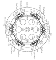
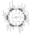
- 7 is a cross-sectional view taken along line VII-VII in FIG. 8 is a cross-sectional view taken along line VIII-VIII in FIG. 9 is a cross-sectional view taken along the line IX-IX in FIG.
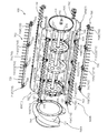
- FIG. 10 is an exploded perspective view of the handling cylinder, showing a state viewed from the front.
- FIG. 10 is an exploded perspective view of the handling cylinder, showing a state viewed from the front.
- FIG. 11 is an exploded perspective view of the handling cylinder, showing a state viewed from the rear.
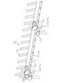
- FIG. 12 is a perspective view of a tooth handling frame provided in the handling cylinder.
- 13 is a cross-sectional view taken along line XIII-XIII in FIG.
- 1 to 4 show a left side view, a right side view, a plan view, and a transmission schematic diagram of the combine 1, respectively.
- the combine 1 includes a traveling machine body 10, a pair of left and right traveling crawlers 20 connected to the traveling machine body 10, an engine 25 mounted on the traveling machine body 10, A transmission 30 inserted in a transmission path from the engine 25 to the traveling crawler 20; an operating unit 40 mounted on the traveling machine body 10; a cutting unit 100 connected to the front of the traveling machine body 10; A threshing device 200 for threshing the harvested cereals harvested by the reaping unit 100 and a Glen tank 50 for storing the grains generated by the threshing device 200 are provided.
- the operating unit 40 is disposed at the front of the traveling machine body 10 and on one side in the machine body width direction.
- the one side and the other side in the body width direction mean the right side and the left side of the combine 1 in the forward direction.
- the driving unit 40 includes a driver seat 41 on which a driver can be seated and various operation members arranged in the vicinity of the driver seat 41.
- the operation members include a steering operation member 42 that changes the traveling direction of the combine 1, a main transmission operation member 43 and a sub-transmission operation member 44 that change the traveling speed of the combine 1, driving of the threshing device 200, and A threshing clutch operating member 45 for switching the stop and a cutting clutch operating member 46 for switching the driving and stopping of the reaping device 100 are included.
- the engine 25 is supported by the traveling machine body 10 using a space below the operation unit 40.
- the engine 25 includes an engine body 26 supported by the traveling machine body 10 in a space below the operation unit 40, a first output shaft 27a extending from the engine body 26 to the other side in the machine body width direction, and the engine It has the 2nd and 3rd output shafts 27b and 27c extended from the main body 26 to the one body width direction side.
- the transmission 30 is configured to change the rotational power operatively input from the engine 25 and output it to the pair of traveling crawlers 20.
- the transmission 30 is disposed below the driving unit 40 in front of the engine 25.
- the transmission 30 includes a transmission case 31 supported by the traveling body 10, a transmission input shaft 32 extending from the transmission case 31 to the other side in the body width direction, and the transmission input shaft 32. And a speed change mechanism that changes the input rotational power.
- the transmission 30 is a hydraulic continuously variable transmission (HST) that performs a continuously variable transmission in response to an operation on the main transmission operating member 43 as the transmission mechanism.
- a main transmission 35 (see FIG. 4) and the like, a gear-type transmission that operatively inputs rotational power from the main transmission 35, and performs multi-stage transmission in response to an operation on the auxiliary transmission operation member 44, and the like Auxiliary transmission device (not shown).
- the pump shaft of the HST 35 functions as the transmission input shaft 32.
- the reaping device 100 is connected to the traveling machine body 10 so as to be movable up and down, and the height can be adjusted by a lifting hydraulic cylinder device 60 (see FIG. 1).
- the lifting hydraulic cylinder device 60 is supplied with hydraulic oil from a hydraulic pump 28 (see FIG. 4) attached to the engine 25.
- the reaping device 100 is disposed in the feeder house 110 and a feeder house 110 that defines a conveyance path for sending the reaped cereals toward the mouth provided in the front portion of the handling chamber 201 in the threshing device 200.
- Supply conveyor 115 a horizontally long bucket-shaped grain header 120 connected to the front end of the feeder house 110, a scraping auger 125 disposed in the grain header 120, and above and above the scraping auger 125.
- a cutting reel 140 provided with a tine bar and a cutting blade 140 disposed in front of and below the scraping auger 125.
- the supply conveyor 115 is disposed along the body width direction on the conveyance direction end side (rear side) along the body width direction on the cutting input shaft 116 disposed on the conveyance direction start end side (front side).
- the lifting hydraulic cylinder device 60 (see FIG. 1) is interposed between the lower surface of the feeder house 110 and the traveling machine body 10, and the reaping device 100 includes the lifting hydraulic cylinder.
- the device 60 can move up and down around the cutting input shaft 116.
- the harvesting device 100 further includes a pair of left and right weed bodies 150 extending forward from both sides of the grain header 120 in the body width direction. Yes.
- the uncut rice culm between the pair of right and left weed bodies 150 is cut by the cutting blade 140 while the tip side is being scraped by the scraping reel 130.
- the harvested cereals harvested by the cutting blade 140 are collected in the grain header 120 by the scraping auger 125 in the vicinity of the front end opening of the feeder house 110, and from the front end opening of the feeder house 110 by the supply conveyor 115. It is transported toward the rear end opening and put into the handling chamber 201 from the handling opening.
- the combine 1 includes a front rotor mechanism 160 that feeds the harvested cereals fed from the supply conveyor 115 to the handling port of the handling chamber 201. ing.
- the front rotor mechanism 160 includes a front rotor drive shaft 161 along the body width direction between the conveyance end of the supply conveyor 115 and the handling port, and a front supported by the front rotor drive shaft 161 so as not to be relatively rotatable.
- the harvested cereal mash that has been transported to the transport end of the supply conveyor 115 is put into the handling chamber 201 from the handling opening by the front rotor 162. .
- the threshing apparatus 200 includes a handling chamber 201 formed by a machine frame erected on the traveling machine body 10, and a handling cylinder shaft disposed along the front-rear direction. 210, a handling cylinder 600 according to the present embodiment housed in the handling chamber 201 in a state of being rotationally driven by the handling cylinder shaft 210, and a receiving net 230 (below the handling cylinder 220) 1). Details of the barrel 600 will be described later.
- cereals threshed from the harvested cereal culm by the handling barrel 600 are selected by the threshing apparatus 200 as described below. A sorting process is performed by the mechanism 250. On the other hand, cereals such as sawdust larger than the mesh opening of the receiving net 230 are discharged from a dust outlet 205 provided behind the handling chamber 201 by the conveying action of the handling cylinder 220.
- a plurality of dust feeding valves (not shown) whose mounting angle can be changed are provided above the handling cylinder 220, and the grain removal in the handling chamber 201 is performed by changing the mounting angle of the dust feeding valve.
- the conveyance speed of the image may be adjustable.
- the threshing apparatus 200 further includes the grain sorting mechanism 250 that sorts grains from the thresh leaked from the receiving net 230.
- the grain sorting mechanism 250 includes a swing sorting body 260 that performs specific gravity sorting on the cereals leaked from the receiving net 230, and a sorting wind supply that feeds the sorting wind toward the swing sorting body 260.
- a body 280 A body 280.
- the swing sorting body 260 includes a swing sorting drive shaft 261 driven by power operatively transmitted from the engine 25 and a swing sorting board 265 swung by the swing sorting drive shaft 261.
- the swing sorter 265 includes Glen pan, chaff sheave, Glen sheave, Strollac, and the like.
- the selected wind supply body 280 has a red pepper shaft 281 driven by power operatively transmitted from the engine 25, and a red pepper fan 285 driven by the red pepper shaft 281.
- the grain sorting mechanism 250 further selects a grain (the first thing such as a refined grain) selected from the cereal by the specific gravity sorting action by the swing sorter 260 and the wind sorting action by the sorting wind supply body 280.
- the first container 301 to be aggregated, the first conveyor mechanism 310 disposed in the first container 301, and the first object sent by the first conveyor mechanism 310 are conveyed into the Glen tank 50.
- the second and third output shafts 27b and 27c of the engine 25 drive the hydraulic pump 28 and the cooling fan 29, respectively.
- the first output shaft 27 a of the engine 25 outputs a traveling system rotational power for driving the traveling member 20.
- the first output shaft 27a is operatively connected to the transmission input shaft 32 via a traveling endless transmission mechanism 400 such as a pulley transmission mechanism.
- the first output shaft 27a further outputs work system rotational power for driving the threshing apparatus 200 and the reaping apparatus 100.
- the working system rotational power is transmitted to the threshing device 200 and the reaping device 100 via a pipe shaft 500 that is extrapolated so as to be relatively rotatable on one side in the body width direction of the tang shaft 281. It has become so.
- the tang shaft 281 is supported by a machine frame that forms the handling chamber 201 so as to be rotatable about its axis, and of the tang shaft 281, a machine that forms the handling chamber 201.
- the pipe shaft 500 is extrapolated so as to be relatively rotatable at a portion extending from the frame to one side in the body width direction (one side in the body width direction of the tang shaft 281).
- the first output shaft 27a is operatively connected to the pipe shaft 500 via a first working endless transmission mechanism 410 such as a pulley transmission mechanism.
- the first working system endless body transmission mechanism 410 is connected to the threshing device 200 and the reaping device 100 from the engine 25 in response to an operation on the threshing clutch operating member 45.
- a threshing clutch 290 for engaging and disengaging power transmission is inserted.
- a handling cylinder input shaft 510 is provided in front of the handling chamber 201 along the body width direction.
- the handling cylinder input shaft 510 is supported by a transmission case 520 disposed in front of the handling chamber 201 so as to be rotatable about its axis.
- the barrel input shaft 510 has one side in the body width direction extending outward from the transmission case 520, and is positioned in a gap between the operation unit 40 and the threshing apparatus 200 in the body width direction.
- the other side of the machine body width direction is supported in the transmission case 520 so as to be rotatable about its axis while being inserted into the transmission case 520.
- the pipe shaft 500 is operatively connected to the handling cylinder input shaft 510 via a second working system endless body transmission mechanism 420 such as a pulley transmission mechanism.
- a second working system endless body transmission mechanism 420 such as a pulley transmission mechanism.
- the front end of the handling cylinder shaft 210 is inserted into the transmission case 520 and is operatively connected to the handling cylinder input shaft 510 in the transmission case 520.
- the other side in the body width direction of the handling cylinder input shaft 510 is terminated in the transmission case 520, and the handling cylinder shaft 210 is interposed in the transmission case via a bevel gear mechanism 530. Operatively connected to the front end of the.
- a work system extending in the body width direction with one side in the body width direction connected to the other side in the body width direction of the barrel input shaft 510 in the transmission case 520 so as not to be relatively rotatable around the axis.
- a transmission shaft 540 is provided, and rotational power from the engine 25 is transmitted to the reaping device 100 and the sorting mechanism 250 via the work system transmission shaft 540.
- the working system transmission shaft 540 is connected to the handling cylinder input shaft 510 so as not to be relatively rotatable around the axis by using the bevel gear mechanism 530.
- the drive-side bevel gear of the bevel gear mechanism 530 is provided with a spline hole into which the other side in the machine body width direction of the barrel input shaft 510 is inserted so as not to be relatively rotatable, and the work system transmission shaft 540 has one side in the machine body width direction. The side is inserted into the spline hole of the drive side bevel gear so as to be connected to the cylinder input shaft 510 so as not to rotate relative to the axis.
- the combine 1 has the front rotor mechanism 160, and power is transmitted from the work system transmission shaft 540 to the reaping device 100 via the front rotor drive shaft 161.
- the working system transmission shaft 540 is operatively connected to the front rotor drive shaft 161 via a third working system endless body transmission mechanism 430 such as a pulley transmission mechanism.
- the third working system endless body transmission mechanism 430 is provided with a cutting clutch 190 that engages and disengages power transmission in response to an operation on the cutting clutch operating member 46. .
- the front rotor drive shaft 161 is operatively connected to the cutting input shaft 116 via a fourth working endless transmission mechanism 440 such as a sprocket transmission mechanism.
- a forward / reverse switching mechanism 170 is interposed between the front rotor drive shaft 161 and the cutting input shaft 116, and the fourth work system endless
- the body transmission mechanism 440 transmits rotational power from the front rotor drive shaft 161 to the forward / reverse switching mechanism 170.
- a cutting transmission shaft 105 is disposed coaxially with the cutting input shaft 116 on the other side in the body width direction of the cutting input shaft 116, and the front rotor driving shaft 161 is connected to the fourth working system transmission mechanism 455. Is operatively connected to the cutting transmission shaft 105 via The forward / reverse switching mechanism 170 is interposed between the cutting transmission shaft 105 and the cutting input shaft 116.
- the grain header 120 is provided with a header drive shaft 121 along the width direction of the machine body and a scraping shaft 122 along the width direction of the body while supporting the scraping auger 125, and the cutting input shaft 116.
- One side in the body width direction is operatively connected to the header drive shaft 121 via a header drive chain 460, and the header drive shaft 121 is operatively connected to the take-up shaft 122 via a take-up drive chain 461.
- the drive shaft 122 is operatively connected to a reel shaft 131 that supports the drive reel 130.
- the scraping shaft 122 is operatively connected to the intermediate shaft 466 via a first reel drive chain 465, and the intermediate shaft 466 is operatively connected to the reel shaft 131 via a second reel drive chain 467. .
- header drive shaft 121 is also operatively connected to the cutting blade 140 via a cutting blade drive crank mechanism 470.
- the working system transmission shaft 540 is also operatively connected to the flange shaft 281 via a fifth working system endless body transmission mechanism 450 such as a pulley transmission mechanism.
- the first conveyor mechanism 310 includes a first conveyor shaft 311 provided in the first basket 301 and a first conveyor 312 provided on the first conveyor shaft 311. And have.
- the cereal conveyor mechanism 320 is disposed in a cereal cylinder 325 having a lower end side communicated with one side in the body width direction of the first basket 301 and an upper end side communicated with an inlet of the Glen tank 50, and a lower end side thereof. It has a cerealing shaft 321 operatively connected to the first conveyor shaft 311 and a cerealing conveyor 322 provided on the cerealing shaft 321.
- the second conveyor mechanism 330 has a second conveyor shaft 321 disposed in the second basket 302 and a second conveyor 322 provided on the second conveyor shaft 321.
- the second return conveyor mechanism 340 has a lower return side that communicates with one side in the body width direction of the second basket 302 and an upper end that opens toward the sorting start end side of the swing sorter 265. And a second reduction shaft 341 operatively connected to the second conveyor shaft 321 and a second reduction conveyor 342 provided on the second reduction shaft 341.
- the other side in the body width direction of the tang shaft 281 is operatively connected to the other side in the body width direction of the first conveyor shaft 311 and the second conveyor shaft 321 via the pulley transmission mechanism 480 for conveyor. .
- the other side in the machine width direction of the second conveyor shaft 321 is operatively connected to the other side in the machine width direction of the swing sorting shaft 261 via a pulley sorting pulley transmission mechanism 485.
- FIG. 5 and 6 show a side view and a perspective view of the handling cylinder 600, respectively.
- 7 to 9 are sectional views taken along lines VII-VI, VIII-VIII, and IX-IX in FIG. 5, respectively.
- 10 and 11 are exploded perspective views of the handling cylinder 600.
- FIG. 5 and 6 show a side view and a perspective view of the handling cylinder 600, respectively.
- 7 to 9 are sectional views taken along lines VII-VI, VIII-VIII, and IX-IX in FIG. 5, respectively.
- 10 and 11 are exploded perspective views of the handling cylinder 600.
- the handling cylinder 600 is wound around the front plate 620 and the rear plate 630 fixed to the handling cylinder shaft 210, and the front plate 620 and the rear plate 630.
- a shielding plate 650 and a plurality of tooth handling frames 700 detachably fixed to the outer surface of the shielding plate 650 are provided.
- the front plate 620 includes a front radial extending portion 621 that is supported relatively non-rotatably on the handling cylinder shaft 210, and a front side circumference that extends in the circumferential direction of the handling cylinder shaft 210. And a direction extending portion 625.
- the front circumferential extension 625 is fixed to the rear surface of the front radial extension 621 by welding or the like.
- the rear plate 630 includes a rear radial extension 631 fixed to the handling shaft 210 so as to face the front radial extension 621, and A rear circumferential direction extending portion 635 extending in the circumferential direction of the handling cylinder shaft 210.
- the rear circumferential extension 635 is fixed to the front surface of the rear radial extension 621 by welding or the like.
- the shielding plate 650 is wound around the front plate 620 and the rear plate 630 so as to cooperate with the front plate 620 and the rear plate 630 to form an internal space that covers the periphery of the barrel cylinder 210. ing.
- the shielding plate 650 has a plurality of divided shielding plates that are divided in the circumferential direction of the cylinder barrel 210.
- the shielding plate 650 includes first and second shielding plates 650 (1) and 650 (2) that are substantially divided into two in the circumferential direction of the handling cylinder shaft 210.
- the tooth handling frame 700 has a long support bar 710 and a plurality of tooth handling 730 arranged with a gap along the longitudinal direction of the support bar 710.
- the plurality of tooth handling frames 700 are arranged in the circumferential direction of the handling cylinder shaft 210 with the support bars 710 of the plurality of tooth handling frames 700 being substantially parallel to the handling cylinder shaft 210.
- the plurality of teeth 730 extend radially outward, and are detachably fixed to the front plate 620 and the rear plate 630 with the shielding plate 650 interposed therebetween. ing.
- FIG. 12 is an enlarged perspective view of the tooth handling frame 700.
- the support bar 710 is separated from the long bar body 711 to which the plurality of teeth 730 are fixed and the bar body 711 in the longitudinal direction with respect to each other.
- a plurality of mounting brackets 715 provided on the bar main body 711.
- the bar body 711 is a hollow square pipe. That is, the bar main body 711 is mounted on the barrel 600, and the lower wall and the upper walls 711a and 711b respectively located radially inward and outward of the barrel 210, and the barrel shaft. 210 has first and second side walls 711c and 711d located on one side and the other side in the circumferential direction, respectively.
- the mounting bracket 715 has a front mounting bracket 715F and a rear mounting bracket 715R provided at the same positions as the front plate 620 and the rear plate 630, respectively, with respect to the axial direction of the barrel shaft 210.
- Each of the front side mounting bracket 715F and the rear side mounting bracket 715R includes first and second mounting pieces 715a extending to one side and the other side in the width direction of the bar body 711 across the low wall 711a of the bar body 711. 715b, a first connecting piece 715c for connecting the first side wall 711c of the bar body 711 and the first mounting piece, and a second side for connecting the second side wall of the bar body 711 and the second mounting piece 715b. And a connecting piece 715d.
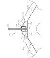
- FIG. 13 is a cross-sectional view taken along line XIII-XIII in FIG.
- the plurality of teeth 730 have lower ends extending from the lower wall 711 a of the bar body 711 inward in the radial direction of the barrel cylinder 210, and upper ends of the bar body 711.
- the bar body 711 is fixed to the lower wall 711a and the upper wall 711b of the bar main body 711 by welding or the like in a state of extending from the upper wall 711b to the outer side in the radial direction of the handling cylinder shaft 210.
- the mounting bracket 715 has a gap 765 between the lower wall 711 a of the bar body 711 and the shielding plate 650 so that the lower end portion of the handle 730 does not interfere with the shielding plate 650.
- the bar main body 711 can be disposed on the shielding plate 650.
- FIG. 13 the following second intermediate mounting bracket 715C (2) optionally provided in the handling cylinder 600 according to the present embodiment is shown.
- the second intermediate mounting bracket 715C (2) and the first intermediate mounting bracket 715C (1) described below have the same configuration as the front mounting bracket 715F and the rear mounting bracket 715R.
- the tooth handling frame 700 is disposed on the outer surface of the shielding plate 650 wound around the front mounting bracket 620 and the rear mounting bracket 630 and sandwiches the shielding plate 650 therebetween. In this state, it is detachably fixed to the front plate 620 and the rear plate 630.
- mounting holes 717 through which fastening members 720 such as bolts are inserted are formed in the first and second mounting pieces 715a and 715b of the mounting bracket 715.
- the plurality of divided shielding plates 650 (1) and 650 (2) constituting the shielding plate 650 correspond in a state where they are wound around the front side circumferential extension portion 625 and the rear side circumferential extension portion 635.
- a through hole 652 is formed at a position facing the mounting hole 717 of the mounting bracket 715.
- a mounting hole 627 is formed at a position corresponding to the mounting hole 717 of the mounting bracket 715 in the front side circumferential extending part 625 and the rear side circumferential extending part 635.
- the plurality of divided shielding plates 650 (1) and 650 (2) are wound around the front-side circumferential extending portion 625 and the rear-side circumferential extending portion 635.
- the plurality of tooth handling frames 700 arranged on the outer surfaces of the plates 650 (1) and 650 (2) are the mounting holes 717 of the mounting bracket 715, the through holes 652 of the shielding plate 650, and the front plate 620.
- the front circumferential extension extends with the plurality of divided shielding plates 650 (1) and 650 (2) sandwiched between the mounting hole 627 and the fastening member 720 inserted through the mounting hole 627 of the rear plate 630. Removably fixed to the existing portion 625 and the rear circumferential extending portion 635.
- the handling cylinder is such that a plurality of the tooth handling frames 700 exist on the outer surfaces of the plurality of divided shielding plates 650 (1), 650 (2).
- the number of the tooth handling frames 700 provided in 600 is larger than the number of the divided shielding plates 650 (1) and 650 (2).
- the shielding plate 650 includes the two divided shielding plates, the first and second divided shielding plates 650 (1) and 650 (2). , Six tooth handling frames 700 are provided. In this case, the three tooth handling frames 700 are disposed on the outer surface of each of the divided shielding plates 650 (1) and 650 (2).
- the shielding plate 650 by providing the shielding plate 650, it is possible to effectively prevent the harvested cereal from entering the internal space of the handling drum 600, while maintaining the tooth handling frame 700 and / or Exchange can be performed easily.
- the handling teeth 730 may be worn or damaged in the handling process for the harvested cereal meal.
- a frame 700 is arranged, and a plurality of (three in the illustrated form) tooth-handling frames 700 allow a single divided shielding plate 650 (1), 650 (2) to be placed on the front plate 620 and the rear plate 630. It is detachably fixed via a fastening member 720.
- At least one of the plurality of divided shielding plates 650 (1) and 650 (2) opens the internal space of the handling cylinder 600 outward.
- An opening (not shown) is provided, and the opening is covered with a cover 655 that is detachably attached to the divided shielding plate via a fastening member 656.
- the front circumferential direction extending portion 625, the rear side circumferential extending portion 635, and the shielding plate 650 include a plurality of radially outward facing portions. When viewed along the axial direction of the cylinder barrel 210, it has a polygonal shape so that the flat surface of the cylinder is arranged in the circumferential direction of the cylinder barrel 210.
- the front circumferential extension 625, the rear circumferential extension 635, and the shielding plate 650 have 12 surfaces when viewed along the axial direction of the handle shaft 210.
- the flat surface 800 has a dodecagonal shape formed by arranging them in the circumferential direction.
- the plurality of tooth handling frames 700 are configured so that the front side circumferentially extending portion 625 and the rear side of the plurality of tooth handling frames 700 sandwich the shielding plate 650 with the support bar 710 positioned on the flat surface 800 of the shielding plate 650. Removably fixed to the corresponding flat surface 800 of the laterally extending portion 635.
- the tooth handling frame 700 is positioned on the outer surface of the shielding plate 650 and the front plate together with the shielding plate 650 via the mounting bracket 715. 620 and the rear plate 630 are fixed.
- the gap 765 may be formed between the surface and the surface facing radially inward.
- the plurality of tooth handling frames 700 are positioned on the flat surface 800 of the shielding plate 650, they are positioned between the adjacent flat surfaces 800 of the shielding plate 650.
- the corner 810 can effectively prevent the harvested cereal meal from being guided radially outward and being caught in the gap 765.
- the front circumferential direction extending portion 625, the rear circumferential direction extending portion 635, and the flat surface 800 of the shielding plate 650 are equal to the number of the plurality of tooth handling frames 700 provided in the handling cylinder 600.
- the number of faces is doubled.
- the handling drum 600 As shown in FIGS. 7 to 9 and the like, the handling drum 600 according to the present embodiment has six tooth handling frames 700. Accordingly, the flat surface 800 has 12 surfaces.
- one tooth handling frame 700 is positioned on one flat surface of the shielding plate 650, and the next tooth handling adjacent to the one side in the circumferential direction of the treatment barrel shaft 210 from the one tooth handling frame 700.
- the frame 700 is positioned on the flat surface 800 that is second adjacent to the one circumferential surface of the barrel shaft 210 from the one flat surface 800.
- the mounting bracket 715 is configured to fit within the corresponding flat surface 800 with respect to the circumferential direction of the handling cylinder shaft 210. This facilitates the work of attaching and detaching the tooth handling frame 700.
- the handling cylinder 600 is supported between the front plate 620 and the rear plate 630 so as not to rotate relative to the handling cylinder shaft 210.
- the second intermediate plate 640 (2 ) And are provided between the first intermediate plate 640 (1) and the first intermediate plate 640 (1) and the rear plate 630.
- Each of the first and second intermediate plates 640 (1) and 640 (2) includes an intermediate radial extending portion 641 that is supported by the handle shaft 210 so as not to rotate relative to the handle shaft 210, and a circumference of the handle shaft 210. And an intermediate circumferential extending portion 645 extending in the direction.
- the plurality of divided shielding plates 650 (1) and 650 (2) constituting the shielding plate 650 include the front circumferential extension 625 and the rear circumferential extension 635,
- the first and second intermediate plates 640 (1) and 640 (2) are also wound around the intermediate week direction extending portion 645.
- the mounting bracket 715 provided on the support bar 710 includes the front mounting bracket 715F and the rear mounting bracket 715R.
- the first and second intermediate plates 640 (1) and 640 (2) have first and second intermediate mounting brackets detachably connected to the first and second intermediate plates 640 (1) and 640 (2) via a fastening member 720, respectively. ), 715C (2).
- the mounting bracket 715 provided on the support bar 710 relates to the front plate 620, the first intermediate plate 640 C (1), the first 2 the intermediate plate 640C (2) and the rear plate 630, the front mounting bracket 715F, the first intermediate mounting bracket 715C (1), the second intermediate mounting bracket 715C (2) and the rear plate 630, respectively.
- a rear mounting bracket 715R is provided.
- the plurality of divided shielding plates 650 (1) and 650 (2) constituting the shielding plate 650 include the front circumferential extension portion 625 and the intermediate circumferential direction extension of the first intermediate plate 640C (1). Portion 645 and the first and second intermediate mounting brackets 715C (1) in a state of being wound around the intermediate circumferential extending portion 645 and the rear circumferential extending portion 635 of the second intermediate plate 640C (2). ), A through hole 652 (see FIGS. 10 and 11) is also formed at a position corresponding to the mounting hole 717 of 715C (2).
- the first intermediate plate 640 (1) and the intermediate circumferential extension 645 of the second intermediate plate 640 (2) have corresponding first and second intermediate attachments respectively.
- a mounting hole is formed at a position facing the mounting hole in the bracket 715.
- the tooth handling frame 710 is disposed on the shielding plate 650, and in addition to the front plate 620 and the rear plate 630 via the fastening member 720, the first and second intermediates.
- the plates 640C (1) and 640C (2) are also detachably fixed.
- the handling part 600B in addition to the handling part 600B formed by the shielding plate 650 and the tooth handling frame 700, the handling part 600B is further forward.
- a scraping portion 600 ⁇ / b> A is provided that conveys the harvested cereal meal toward the handling portion 600 ⁇ / b> B as the handling cylinder shaft 210 rotates.
- the scraping portion 600 ⁇ / b> A is a plurality of spiral blades 760 that convey the harvested cereals toward the handling portion 600 ⁇ / b> B according to the rotation of the handling shaft 210, and the like around the axis of the handling shaft 210. It has a plurality of spiral blades 760 arranged at intervals.
- the scraping portion 600A is supported by the handling cylinder shaft 210 so as not to be relatively rotatable and a rear end surface thereof is connected to the front plate 620 via a fastening member.
- a plurality of spiral blades 760 are provided on the outer peripheral surface of the drum body 750.
- Handling cylinder shaft 600 Handling cylinder 620 Front side plate 621 Front side radial direction extension part 625 Front side circumferential direction extension part 630 Rear side plate 631 Rear side radial direction extension part 635 Rear side circumferential direction extension part 640 (1), 640 (2) 1st and 2nd intermediate
- disassembly shielding board 700 Teeth handle frame 710 Support Bar 711 Bar body 715 Mounting bracket 717 Mounting piece 720 Fastening member 730 Teeth 765 Clearance 800 Flat surface
Landscapes
- Life Sciences & Earth Sciences (AREA)
- Environmental Sciences (AREA)
- Threshing Machine Elements (AREA)
Abstract
La présente invention concerne un tambour de manipulation dans lequel une pluralité de plaques de fermeture divisées de manière circonférentielle sont montées autour de plaques avant et arrière fixées à un arbre de manipulation, et dans cet état, une pluralité de cadres de dent de manipulation sont fixés amovibles aux plaques avant et arrière tout en enserrant les plaques de fermeture divisées. Le nombre de cadres de dent de manipulation est supérieur au nombre de plaques de fermeture divisées, et la pluralité de cadres de dent de manipulation sont agencés sur les surfaces externes, respectivement, de la pluralité de plaques de fermeture divisées.
Priority Applications (1)
| Application Number | Priority Date | Filing Date | Title |
|---|---|---|---|
| CN201780014538.XA CN108882680B (zh) | 2016-03-30 | 2017-02-23 | 脱粒筒 |
Applications Claiming Priority (2)
| Application Number | Priority Date | Filing Date | Title |
|---|---|---|---|
| JP2016-068343 | 2016-03-30 | ||
| JP2016068343A JP6608751B2 (ja) | 2016-03-30 | 2016-03-30 | 扱胴 |
Publications (1)
| Publication Number | Publication Date |
|---|---|
| WO2017169358A1 true WO2017169358A1 (fr) | 2017-10-05 |
Family
ID=59964235
Family Applications (1)
| Application Number | Title | Priority Date | Filing Date |
|---|---|---|---|
| PCT/JP2017/006798 Ceased WO2017169358A1 (fr) | 2016-03-30 | 2017-02-23 | Tambour de manipulation |
Country Status (3)
| Country | Link |
|---|---|
| JP (1) | JP6608751B2 (fr) |
| CN (2) | CN113261433A (fr) |
| WO (1) | WO2017169358A1 (fr) |
Cited By (1)
| Publication number | Priority date | Publication date | Assignee | Title |
|---|---|---|---|---|
| CN110933997A (zh) * | 2018-09-21 | 2020-03-31 | 株式会社久保田 | 脱粒装置及联合收割机 |
Families Citing this family (3)
| Publication number | Priority date | Publication date | Assignee | Title |
|---|---|---|---|---|
| JP6967996B2 (ja) * | 2018-02-27 | 2021-11-17 | 株式会社クボタ | 脱穀装置 |
| JP2020048474A (ja) * | 2018-09-26 | 2020-04-02 | ヤンマー株式会社 | コンバイン |
| JP6975411B2 (ja) * | 2019-12-24 | 2021-12-01 | 井関農機株式会社 | 脱穀装置の扱胴 |
Citations (4)
| Publication number | Priority date | Publication date | Assignee | Title |
|---|---|---|---|---|
| JPS5035762U (fr) * | 1973-07-31 | 1975-04-15 | ||
| JP2012175952A (ja) * | 2011-02-28 | 2012-09-13 | Iseki & Co Ltd | 脱穀用の扱胴 |
| JP2012231703A (ja) * | 2011-04-28 | 2012-11-29 | Iseki & Co Ltd | コンバインの扱胴 |
| JP2015188435A (ja) * | 2014-03-29 | 2015-11-02 | 井関農機株式会社 | 脱穀装置の扱胴 |
Family Cites Families (13)
| Publication number | Priority date | Publication date | Assignee | Title |
|---|---|---|---|---|
| JPS6119428A (ja) * | 1984-07-04 | 1986-01-28 | 井関農機株式会社 | 脱穀機における扱歯装置 |
| JPS62164744U (fr) * | 1986-04-11 | 1987-10-20 | ||
| JP2595991Y2 (ja) * | 1993-07-23 | 1999-06-02 | ヤンマー農機株式会社 | 脱穀装置における扱胴装置 |
| JPH1128019A (ja) * | 1997-07-10 | 1999-02-02 | Kubota Corp | 脱穀装置の扱胴構造 |
| JP2003000039A (ja) * | 2001-06-22 | 2003-01-07 | Kubota Corp | 扱 胴 |
| JP4484779B2 (ja) * | 2005-07-14 | 2010-06-16 | 株式会社クボタ | 脱穀装置の扱胴構造 |
| WO2010047430A1 (fr) * | 2008-10-23 | 2010-04-29 | Xenith Track Co., Ltd | Tambour de battage |
| CN201323787Y (zh) * | 2008-11-28 | 2009-10-14 | 福田雷沃国际重工股份有限公司 | 收割机用轴流滚筒 |
| JP5437117B2 (ja) * | 2010-03-04 | 2014-03-12 | 三菱農機株式会社 | 脱穀装置 |
| JP2012165662A (ja) * | 2011-02-10 | 2012-09-06 | Yanmar Co Ltd | 普通型コンバイン |
| CN103125217B (zh) * | 2011-11-28 | 2015-11-18 | 井关农机株式会社 | 脱粒装置 |
| JP5921370B2 (ja) * | 2012-07-10 | 2016-05-24 | 株式会社クボタ | 脱穀装置 |
| CN204968599U (zh) * | 2015-09-25 | 2016-01-20 | 十堰市双兴净化器有限公司 | 一种全喂入式联合收割机脱粒滚筒装置 |
-
2016
- 2016-03-30 JP JP2016068343A patent/JP6608751B2/ja not_active Expired - Fee Related
-
2017
- 2017-02-23 CN CN202110532892.XA patent/CN113261433A/zh active Pending
- 2017-02-23 WO PCT/JP2017/006798 patent/WO2017169358A1/fr not_active Ceased
- 2017-02-23 CN CN201780014538.XA patent/CN108882680B/zh active Active
Patent Citations (4)
| Publication number | Priority date | Publication date | Assignee | Title |
|---|---|---|---|---|
| JPS5035762U (fr) * | 1973-07-31 | 1975-04-15 | ||
| JP2012175952A (ja) * | 2011-02-28 | 2012-09-13 | Iseki & Co Ltd | 脱穀用の扱胴 |
| JP2012231703A (ja) * | 2011-04-28 | 2012-11-29 | Iseki & Co Ltd | コンバインの扱胴 |
| JP2015188435A (ja) * | 2014-03-29 | 2015-11-02 | 井関農機株式会社 | 脱穀装置の扱胴 |
Cited By (2)
| Publication number | Priority date | Publication date | Assignee | Title |
|---|---|---|---|---|
| CN110933997A (zh) * | 2018-09-21 | 2020-03-31 | 株式会社久保田 | 脱粒装置及联合收割机 |
| CN110933997B (zh) * | 2018-09-21 | 2023-06-27 | 株式会社久保田 | 脱粒装置及联合收割机 |
Also Published As
| Publication number | Publication date |
|---|---|
| CN108882680A (zh) | 2018-11-23 |
| JP2017176035A (ja) | 2017-10-05 |
| CN108882680B (zh) | 2021-06-08 |
| CN113261433A (zh) | 2021-08-17 |
| JP6608751B2 (ja) | 2019-11-20 |
Similar Documents
| Publication | Publication Date | Title |
|---|---|---|
| JP5828581B2 (ja) | 普通型コンバイン | |
| JP6608751B2 (ja) | 扱胴 | |
| JP2011250751A (ja) | 普通型コンバイン | |
| JP6473052B2 (ja) | 扱胴 | |
| JP7166394B2 (ja) | 扱胴 | |
| JP5902336B1 (ja) | 扱胴 | |
| JP2014064519A (ja) | コンバイン | |
| JP6009603B1 (ja) | 扱胴 | |
| WO2012111233A1 (fr) | Moissonneuse de type classique | |
| WO2016093201A1 (fr) | Moissonneuse-batteuse | |
| WO2016204171A1 (fr) | Cylindre de battage | |
| WO2012108459A1 (fr) | Moissonneuse de type classique | |
| JP2017093307A (ja) | コンバイン | |
| CN107426967B (zh) | 脱粒筒 | |
| JP6270283B2 (ja) | コンバイン | |
| JP6208651B2 (ja) | コンバイン伝動構造 | |
| JP5797940B2 (ja) | コンバインの扱胴 | |
| JP2014077383A (ja) | コンバイン | |
| JP2017006036A (ja) | 扱胴 | |
| JP2011250750A (ja) | 普通型コンバイン | |
| JP6967996B2 (ja) | 脱穀装置 | |
| JP6482491B2 (ja) | コンバイン | |
| JP6320314B2 (ja) | コンバイン伝動構造 | |
| JP2014075993A (ja) | コンバイン | |
| JP2011250752A (ja) | 普通型コンバイン |
Legal Events
| Date | Code | Title | Description |
|---|---|---|---|
| NENP | Non-entry into the national phase |
Ref country code: DE |
|
| 121 | Ep: the epo has been informed by wipo that ep was designated in this application |
Ref document number: 17773903 Country of ref document: EP Kind code of ref document: A1 |
|
| 122 | Ep: pct application non-entry in european phase |
Ref document number: 17773903 Country of ref document: EP Kind code of ref document: A1 |