WO2017169625A1 - Composant électronique rotatif - Google Patents
Composant électronique rotatif Download PDFInfo
- Publication number
- WO2017169625A1 WO2017169625A1 PCT/JP2017/009460 JP2017009460W WO2017169625A1 WO 2017169625 A1 WO2017169625 A1 WO 2017169625A1 JP 2017009460 W JP2017009460 W JP 2017009460W WO 2017169625 A1 WO2017169625 A1 WO 2017169625A1
- Authority
- WO
- WIPO (PCT)
- Prior art keywords
- shaft
- contact
- encoder
- electronic component
- contact member
- Prior art date
- Legal status (The legal status is an assumption and is not a legal conclusion. Google has not performed a legal analysis and makes no representation as to the accuracy of the status listed.)
- Ceased
Links
Images








Classifications
-
- H—ELECTRICITY
- H01—ELECTRIC ELEMENTS
- H01H—ELECTRIC SWITCHES; RELAYS; SELECTORS; EMERGENCY PROTECTIVE DEVICES
- H01H25/00—Switches with compound movement of handle or other operating part
- H01H25/06—Operating part movable both angularly and rectilinearly, the rectilinear movement being along the axis of angular movement
-
- H—ELECTRICITY
- H01—ELECTRIC ELEMENTS
- H01H—ELECTRIC SWITCHES; RELAYS; SELECTORS; EMERGENCY PROTECTIVE DEVICES
- H01H19/00—Switches operated by an operating part which is rotatable about a longitudinal axis thereof and which is acted upon directly by a solid body external to the switch, e.g. by a hand
- H01H19/02—Details
- H01H19/10—Movable parts; Contacts mounted thereon
- H01H19/11—Movable parts; Contacts mounted thereon with indexing means
-
- H—ELECTRICITY
- H01—ELECTRIC ELEMENTS
- H01H—ELECTRIC SWITCHES; RELAYS; SELECTORS; EMERGENCY PROTECTIVE DEVICES
- H01H19/00—Switches operated by an operating part which is rotatable about a longitudinal axis thereof and which is acted upon directly by a solid body external to the switch, e.g. by a hand
- H01H19/005—Electromechanical pulse generators
-
- H—ELECTRICITY
- H01—ELECTRIC ELEMENTS
- H01H—ELECTRIC SWITCHES; RELAYS; SELECTORS; EMERGENCY PROTECTIVE DEVICES
- H01H19/00—Switches operated by an operating part which is rotatable about a longitudinal axis thereof and which is acted upon directly by a solid body external to the switch, e.g. by a hand
- H01H19/005—Electromechanical pulse generators
- H01H2019/006—Electromechanical pulse generators being rotation direction sensitive, e.g. the generated pulse or code depends on the direction of rotation of the operating part
-
- H—ELECTRICITY
- H01—ELECTRIC ELEMENTS
- H01H—ELECTRIC SWITCHES; RELAYS; SELECTORS; EMERGENCY PROTECTIVE DEVICES
- H01H2215/00—Tactile feedback
- H01H2215/03—Sound
-
- H—ELECTRICITY
- H01—ELECTRIC ELEMENTS
- H01H—ELECTRIC SWITCHES; RELAYS; SELECTORS; EMERGENCY PROTECTIVE DEVICES
- H01H2221/00—Actuators
- H01H2221/008—Actuators other then push button
- H01H2221/01—Actuators other then push button also rotatable
-
- H—ELECTRICITY
- H01—ELECTRIC ELEMENTS
- H01H—ELECTRIC SWITCHES; RELAYS; SELECTORS; EMERGENCY PROTECTIVE DEVICES
- H01H2223/00—Casings
- H01H2223/008—Casings metallic
-
- H—ELECTRICITY
- H01—ELECTRIC ELEMENTS
- H01H—ELECTRIC SWITCHES; RELAYS; SELECTORS; EMERGENCY PROTECTIVE DEVICES
- H01H2225/00—Switch site location
- H01H2225/004—Switch site location in different planes to increase density
-
- H—ELECTRICITY
- H01—ELECTRIC ELEMENTS
- H01H—ELECTRIC SWITCHES; RELAYS; SELECTORS; EMERGENCY PROTECTIVE DEVICES
- H01H2225/00—Switch site location
- H01H2225/03—Different type of switches
-
- H—ELECTRICITY
- H01—ELECTRIC ELEMENTS
- H01H—ELECTRIC SWITCHES; RELAYS; SELECTORS; EMERGENCY PROTECTIVE DEVICES
- H01H2239/00—Miscellaneous
- H01H2239/026—Internal encoding, e.g. validity bit
Definitions
- the present invention relates to a rotary electronic component.
- the rotary electronic component includes a shaft, a regulating member that regulates the rotation angle of the shaft, and an encoder mechanism that detects the rotation direction and the rotation angle of the shaft.
- the conventional rotary electronic component encoder mechanism has a rotor attached to the shaft and a slider attached to the rotor.
- the restricting member contacts the outer peripheral surface of the rotor and restricts the rotation angle of the shaft.
- the regulating member regulates the rotation angle of the shaft by bringing a ball into contact with the outer peripheral surface of the rotor. Specifically, the ball pressed by the restricting member enters the concave portion on the outer periphery of the rotor and is pressed and held. In the case of downsizing with this structure, high processing accuracy and assembly accuracy of each part are necessary, and it is difficult to realize. It is also difficult to ensure reliability.
- an object of the present invention is to provide a rotary electronic component that can be miniaturized.
- the rotary electronic component of the present invention is A base member; A shaft attached to the base member so as to be rotatable about an axis; A regulating member that regulates the rotation angle of the shaft;
- the shaft has a collar portion including a plurality of convex portions and concave portions alternately arranged in the circumferential direction,
- the regulating member is A contact member that contacts the convex part and the concave part of the shaft; A biasing member that biases the contact member from the radially outer side of the shaft toward the shaft.
- the contact member of the regulating member is urged by the urging member from the radially outer side of the shaft toward the shaft side, and is urged to the convex portion of the shaft flange. While contacting, it fits into the recess of the flange of the shaft to regulate the rotation angle of the shaft.
- the regulating member that regulates the rotation angle of the shaft can be reduced in size with a simple configuration, and as a result, the rotary electronic component can be reduced in size.
- a miniaturized rotary encoder can be provided by providing an encoder mechanism for detecting the rotational direction and rotational angle of the shaft.
- a switch mechanism that is pressed against the shaft by movement along the shaft axis may be provided, and the shaft can be used for both the rotation angle regulating operation and the axial switch operation.
- One end of the contact member is rotatably connected to the base member, and the other end is a free end that contacts the convex portion and the concave portion of the shaft, The urging member is locked to the free end side of the contact member.
- one end of the contact member is rotatably connected to the base member, and the other end of the contact member is a free end that contacts the convex portion and the concave portion of the shaft, and the free end side of the contact member is Since the urging member is locked, the free end of the contact member is constrained to rotate on the arc, and the behavior of the contact member accompanying the rotation of the shaft is stabilized. Thereby, a smooth click feeling is obtained.
- the contact member of the regulating member has a first contact member and a second contact member arranged on both sides of the shaft,
- the biasing member of the regulating member is An elastically deformable base; A first locking portion provided at one end of the base so as to lock to the free end side of the first contact member; And a second locking portion provided at the other end of the base portion so as to be locked to the free end side of the second contact member.
- the biasing member having the elastically deformable base portion and the first and second locking portions locked to the free end sides of the first and second contact members allows the first member of the restricting member.
- the first and second contact members are urged toward the shaft side from the outside in the radial direction of the shaft and come into contact with the convex and concave portions of the flange from both sides of the shaft. A smooth click feeling is obtained as well.
- the first contact member and the second contact member of the restricting member are arranged in plane symmetry with respect to a plane passing through the shaft axis.
- the first contact member and the second contact member of the restricting member are arranged in a plane-symmetrical position with respect to a plane passing through the axis of the shaft.
- the contact state with respect to the convex portion and the concave portion of the flange portion of the shaft is synchronized, so that a smoother click feeling is obtained.
- the convex portion of the flange portion of the shaft is disposed at a plane symmetric with respect to a plane passing through the axis of the shaft,
- the concave portion of the flange portion of the shaft is disposed at a plane symmetric with respect to a plane passing through the shaft axis.
- the convex portion of the flange portion of the shaft is disposed in a plane-symmetrical position with respect to the plane passing through the axis of the shaft, and the concave portion of the flange portion of the shaft is in a plane passing through the shaft axis. Since the first contact member and the second contact member are arranged in plane symmetry with respect to each other, the contact state with respect to the convex portion and the concave portion of the flange portion of the shaft is synchronized, so that a smoother click feeling is obtained. It is done.
- the urging member of the restricting member is held by the base member so as to be movable as a whole within a predetermined range.
- the urging member of the restricting member is held by the base member so that the entire urging member can move within a predetermined range.
- the contact member and the biasing member of the regulating member are locked by curved surfaces that contact each other.
- the contact area between the contact member and the urging member can be increased by locking the contact member and the urging member of the regulating member with the curved surfaces that are in contact with each other.
- the surface pressure decreases, the wear on the contact surface between the contact member and the biasing member can be reduced, and the reliability can be improved.
- a movement restricting member for restricting movement of the restricting member in the axial direction of the shaft is provided.
- the behavior of the restricting member is not disturbed in the axial direction of the shaft as the shaft rotates.
- the regulating member that regulates the rotation angle of the shaft can be reduced in size with a simple configuration. As a result, the rotary electronic component can be reduced in size.
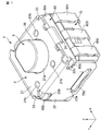
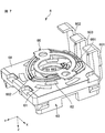
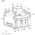
- FIG. 1 is a perspective view seen from above a rotary encoder 1 as an example of a rotary electronic component according to an embodiment of the present invention.
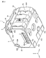
- FIG. 2 is a perspective view of the rotary encoder 1 as viewed from below.
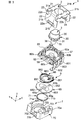
- FIG. 3 is an exploded perspective view of the rotary encoder 1 as viewed from above.
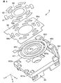
- FIG. 4 is an exploded perspective view of the rotary encoder 1 as viewed from below.
- FIG. 5 is a sectional view of the rotary encoder 1.
- the width direction of the rotary encoder 1 is defined as the X direction
- the length direction of the rotary encoder 1 is defined as the Y direction
- the height direction of the rotary encoder 1 is taken as the Z direction.
- the positive direction in the Z direction is the upper side
- the negative direction in the Z direction is the lower side.
- the rotary encoder 1 includes a casing 2, a shaft 3 attached to the casing 2 so as to be rotatable about the axis and movable along the axis, and the shaft 3.
- a regulating member click spring 55, pendulum 56, 57
- the regulating member click spring 55, pendulum 56, 57
- encoder mechanism 6 and switch mechanism 7 are arranged along the axis of the shaft 3 in order from the upper side to the lower side.
- the click spring 55 is an example of a contact member.
- the pendulum 56 is an example of a first contact member
- the pendulum 57 is an example of a second contact member.
- Casing 2 is made of metal, for example.
- the shaft 3 In the casing 2, the shaft 3, the regulating member (click spring 55, pendulum 56, 57), the encoder mechanism 6, and the switch mechanism 7 are assembled together.
- the casing 2 includes an upper wall 21, side walls 22, 22 provided on both sides of the upper wall 21 in the X direction and extending downward, and a protruding wall provided in the positive direction of the upper wall 21 in the Y direction and extending downward. 23 and a protruding piece 24 provided in the negative direction of the upper wall 21 in the Y direction and extending downward.
- the upper wall 21 has one hole 21a and four recesses 21b around the hole 21a.
- the side wall 22 has a hole 22a on the lower side and a groove 22b on the upper side.
- a locking portion 22c that protrudes inside the casing 2 is provided.
- the protruding wall 23 extends over the entire length of the upper wall 21 in the X direction.
- the projecting piece 24 is provided at the center of the upper wall 21 in the X direction.
- the shaft 3 is made of, for example, resin.
- the shaft 3 includes an operation portion 35, a gear-shaped flange portion 30, and an end portion 36.
- the operation part 35, the gear-shaped flange part 30, and the end part 36 are arranged in order from the upper side to the lower side along the axis.
- the operation unit 35 has a notch that serves as a mark for the rotation of the shaft 3.
- the gear-shaped collar part 30 includes a plurality of convex parts 31 and concave parts 32.
- the plurality of convex portions 31 and concave portions 32 are alternately arranged in the circumferential direction.
- the operation unit 35 penetrates the hole 21 a of the upper wall 21 of the casing 2, and the user can operate the operation unit 35 from the outside of the casing 2.
- the encoder mechanism 6 includes an encoder board 60 as an example of a base member, resistor patterns 61, 62, and 63 provided on the encoder board 60, and an encoder board 60 that is electrically connected to the resistor patterns 61, 62, and 63.
- Encoder terminals 601, 602, and 603 that are connected to each other, a rotor 65 that is attached to the shaft 3 so as to be rotatable together with the shaft 3, and a slide that is attached to the rotor 65 and slidably contacts the resistor patterns 61, 62, and 63.
- a mover 66 is an encoder board 60 as an example of a base member, resistor patterns 61, 62, and 63 provided on the encoder board 60, and an encoder board 60 that is electrically connected to the resistor patterns 61, 62, and 63.
- Encoder terminals 601, 602, and 603 that are connected to each other, a rotor 65 that is attached to the shaft 3 so as to be
- the encoder board 60 is made of resin, for example.
- a regulating member (click spring 55, pendulum 56, 57) is attached to the upper surface 60a of the encoder board 60.
- Protrusions 60b are provided on both sides of the encoder board 60 in the X direction.
- the protrusion 60 b is fitted in the groove 22 b of the side wall 22 of the casing 2.
- Both sides of the encoder board 60 in the Y direction are sandwiched between the protruding wall 23 and the protruding piece 24.
- the encoder board 60 is fixed to the casing 2 by the groove 22b of the side wall 22, the protruding wall 23, and the protruding piece 24.
- the groove portion 22 b of the side wall 22, the protruding wall 23, and the protruding piece 24 constitute an encoder fixing portion that fixes the encoder board 60.
- Resistor patterns 61, 62, and 63 are provided on the lower surface of the encoder board 60.
- the resistor patterns 61, 62, and 63 are for detecting the rotation direction and rotation angle of the shaft 3.
- the first resistor pattern 61, the second resistor pattern 62, and the third resistor pattern 63 are formed in an annular shape and arranged concentrically.
- the first resistor pattern 61, the second resistor pattern 62, and the third resistor pattern 63 are sequentially arranged from the outer side to the inner side in the radial direction.
- the first resistor pattern 61 and the second resistor pattern 62 are each formed intermittently.
- the third resistor pattern 63 is formed continuously.
- Encoder terminals 601, 602, and 603 are insert-molded on the encoder board 60.
- the first encoder terminal 601 is electrically connected to the first resistor pattern 61
- the second encoder terminal 602 is electrically connected to the second resistor pattern 62
- the third encoder terminal 603 is a third resistor.
- the body pattern 63 is electrically connected.
- the rotor 65 is positioned in the circumferential direction with respect to the shaft 3 and is movable in the axial direction. More specifically, the rotor 65 has a D-shaped hole 65a. The outer peripheral surface of the end portion 36 of the shaft 3 is formed in a D shape. The D-shaped end portion 36 is fitted into the D-shaped hole 65a, so that the rotor 65 is fixed to the shaft 3 in the circumferential direction and is not fixed in the axial direction.
- the rotor 65 is formed in a substantially oval shape.
- the rotor 65 has a long diameter portion 651 in which the outer diameter of the rotor 65 is a long diameter, and a short diameter portion 652 in which the outer diameter of the rotor 65 is a short diameter.
- the length of the long diameter portion 651 is larger than the gap between the locking portions 22c of the opposite side walls 22, and the length of the short diameter portion 652 is smaller than the gap between the locking portions 22c of the opposite side walls 22.
- the locking portion 22 c is configured such that the short diameter portion 652 is detached without locking and the long diameter portion 651 can be engaged and disengaged by the rotation of the rotor 65.
- the slider 66 is made of metal, for example.
- the slider 66 is fixed to the two protrusions 65 b on the upper surface of the rotor 65.
- the slider 66 is formed in an annular shape.
- the slider 66 has a first contact portion 661, a second contact portion 662, and a third contact portion 663.
- the first contact portion 661, the second contact portion 662, and the third contact portion 663 are sequentially arranged from the outer side to the inner side in the radial direction.
- the first contact part 661, the second contact part 662, and the third contact part 663 are electrically connected.
- the first contact portion 661 can contact the first resistor pattern 61
- the second contact portion 662 can contact the second resistor pattern 62
- the third contact portion 663 can contact the third resistor pattern 63. It becomes possible to contact.
- the switch mechanism 7 includes a switch board 70, first to third switch terminals 701, 702, and 703 provided on the switch board 70, and a conductor provided on the switch board 70 and pressed against the end portion 36 of the shaft 3. 71.
- the conductor 71 is electrically connected to the first and second switch terminals 701 and 702.
- the conductor 71 is pressed by the end portion 36 of the shaft 3 and is electrically connected to the third switch terminal 703 to conduct the first and second switch terminals 701 and 702 and the third switch terminal 703.
- the switch signal is turned on.
- each function operates when the switch signal is turned on. Note that only one of the first and second switch terminals 701 and 702 may be provided.
- Projections 70b are provided on both sides of the switch board 70 in the X direction.
- the protrusion 70 b is fitted in the hole 22 a of the side wall 22 of the casing 2.
- the switch board 70 is fixed to the casing 2 by the hole 22 a of the side wall 22.
- the hole 22 a of the side wall 22 constitutes a switch fixing portion that fixes the switch substrate 70.
- a stepped portion 70c is provided on one side of the lower surface of the switch substrate 70 in the X direction. End portions of the bent encoder terminals 601, 602, and 603 are locked to the stepped portion 70c. That is, the encoder board 60 and the switch board 70 are integrally held by the bent encoder terminals 601, 602, and 603.
- the depth of the stepped portion 70c is deeper than the thickness of the encoder terminals 601, 602, 603.
- the first to third switch terminals 701, 702, and 703 are insert-molded on the switch board 70.
- the third switch terminal 703 is located between the first switch terminal 701 and the second switch terminal 702.
- the conductor 71 has elasticity.
- the conductor 71 is formed in a dome shape.
- the conductor 71 is fitted in the recess 70 a on the upper surface of the switch substrate 70.
- the peripheral portion 71 a of the conductor 71 is electrically connected to the first and second switch terminals 701 and 702.
- the zenith portion 71 b of the conductor 71 is separated from the third switch terminal 703 in the free state of the conductor 71, while being pressed by the end portion 36 of the shaft 3 and electrically connected to the third switch terminal 703.
- the end portion 36 of the shaft 3 presses the zenith portion 71 b of the conductor 71, and the zenith portion 71 b of the conductor 71 is electrically connected to the third switch terminal 703. Is done.
- the first and second switch terminals 701 and 702 and the third switch terminal 703 are electrically connected, and the switch signal is turned on.
- the conductor 71 returns to the free state, so that the shaft 3 moves upward, and the zenith portion 71b of the conductor 71 is separated from the third switch terminal 703. .
- the first and second switch terminals 701 and 702 and the third switch terminal 703 are not electrically connected, and the switch signal is turned off.
- FIG. 6 is an exploded perspective view of the encoder mechanism 6 as viewed from below.
- first, second, and third electrode portions 671, 672, and 673 are provided on the lower surface of the encoder substrate 60.
- the 1st electrode part 671, the 2nd electrode part 672, and the 3rd electrode part 673 are formed in an annular shape, and are arranged concentrically.
- the 1st electrode part 671, the 2nd electrode part 672, and the 3rd electrode part 673 are arranged in order from the outside in the diameter direction to the inside.
- the first electrode portion 671 is electrically connected to the end portion 601a of the first encoder terminal 601
- the second electrode portion 672 is electrically connected to the end portion 602a of the second encoder terminal 602
- the third electrode portion. 673 is electrically connected to the end 603a of the third encoder terminal 603.
- An insulating sheet 68 is laminated on the first, second, and third electrode portions 671, 672, and 673.
- the insulating sheet 68 includes a first electrode portion 671 and a second electrode portion 672 so that the first electrode portion 671 is intermittently exposed in the circumferential direction and the second electrode portion 672 is intermittently exposed in the circumferential direction. Cover. That is, the insulating sheet 68 has a plurality of holes 68 a that are intermittently arranged in the circumferential direction, and the first electrode part 671 and the second electrode part 672 are exposed from the hole 68 a of the insulating sheet 68.
- the third electrode portion 673 is not covered with the insulating sheet 68.
- a first resistor pattern 61 is provided in a portion where the first electrode portion 671 is exposed from the insulating sheet 68; a second resistor pattern 62 is provided in a portion where the second electrode portion 672 is exposed from the insulating sheet 68; A third resistor pattern 63 is provided on the third electrode portion 673.
- the first resistor pattern 61 is electrically connected to the first encoder terminal 601 via the first electrode portion 671
- the second resistor pattern 62 is connected to the first electrode portion 672 via the second electrode portion 672
- 2 is electrically connected to the encoder terminal 602
- the third resistor pattern 63 is electrically connected to the third encoder terminal 603 via the third electrode portion 673.
- FIG. 7 is a perspective view of the encoder mechanism 6 as viewed from below. As shown in FIG. 7, the first contact portion 661 of the slider 66 is at a position corresponding to the first resistor pattern 61, and the second contact portion 662 of the slider 66 is the second resistor pattern 62. The third contact portion 663 of the slider 66 is at a position corresponding to the third resistor pattern 63.
- the first contact portions 661 are alternately brought into contact with the first resistor pattern 61 and the insulating sheet 68, and the second contact portion 662 is contacted with the second resistor pattern 62 and the insulating sheet. 68 and alternately contact.
- the third contact portion 663 is always in contact with the third resistor pattern 63. That is, by the rotation of the slider 66, the first encoder terminal 601 and the third encoder terminal 603 are intermittently electrically connected, and the second encoder terminal 602 and the third encoder terminal 603 are intermittently connected. Electrically connected.
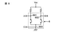
- FIG. 8 is a circuit diagram showing an equivalent circuit of the encoder mechanism 6.
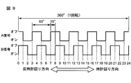
- FIG. 9 is a waveform diagram showing an output waveform of the encoder mechanism 6.
- a current flows between the points A and C, and the A signal is turned on.
- the second encoder terminal 602 and the third encoder terminal 603 are electrically connected, a current flows between point B and point C, and the B signal is turned on.
- the rotation angle of the slider 66 from the start of turning off the A signal to the start of the next off is 60 deg.
- the difference between the start of turning off the A signal and the start of turning off the B signal is 15 deg at the rotation angle of the slider 66.
- the change in the combination of ON and OFF of the A signal and the B signal is divided into 24. That is, it can be determined that the rotation angle of the slider 66 changes every 15 degrees in one rotation of the slider 66. Therefore, by determining changes in the A signal and the B signal, the rotation direction and rotation angle (rotation amount) of the slider 66 can be determined.
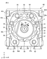
- FIG. 10 is a plan view of the encoder board 60, the shaft 3, and the restricting members (click springs 55, pendulums 56, 57).
- FIG. 11 is an exploded perspective view of the encoder board 60 and the restricting members (click spring 55, pendulum 56, 57).
- the regulating members (click spring 55, pendulum 56, 57) are arranged so as to surround the flange 30 of the shaft 3 when viewed from the direction of the axis 3a of the shaft 3.
- the pendulums 56 and 57 are made of, for example, a rigid body such as metal.
- the pendulums 56 and 57 are provided at annular base portions 56a and 57a provided with through holes 56d and 57d, arm portions 56b and 57b extending from the annular base portions 56a and 57a, and distal ends (free ends) of the arm portions 56b and 57b.
- Contact portions 56c and 57c With the two hinge pins 82 provided on the upper surface 60a of the encoder board 60 being inserted into the through holes 56d and 57d of the pendulums 56 and 57, each of the pendulums 56 and 57 is rotatably connected to the encoder board 60. ing.
- the contact portion 56c of the pendulum 56 also serves as the first locking portion
- the contact portion 57c of the pendulum 56 also serves as the second locking portion.
- each of the pendulums 56 and 57 is rotatably connected to the encoder board 60. May be.
- the click spring 55 is held on the upper surface 60a of the encoder board 60 so as to be movable as a whole within a predetermined range.
- the click spring 55 is provided at one end of the base portion 55a so as to be engaged with the U-shaped elastically deformable base portion 55a so as to surround the outer periphery of the flange portion 30 and the contact portion 56c side of the pendulum 56.
- the first locking portion 55b, a stopper portion 55c projecting outward from one end of the base portion 55a, and a second portion provided at the other end of the base portion 55a so as to be locked to the contact portion 57c side of the pendulum 57.
- Two locking portions 55d and a stopper portion 55e protruding outward from one end of the base portion 55a.
- contact portions 60 c and 60 d are provided at the corners of the encoder substrate 60.
- the stopper portion 55c of the click spring 55 is disposed at a distance from the contact portion 60c of the encoder substrate 60.
- the stopper portion 55e of the click spring 55 is disposed at a distance from the contact portion 60d of the encoder substrate 60.
- first locking portion 55 b and the second locking portion 55 d of the click spring 55 have arc-shaped convex surfaces 111 and 112 (curved surfaces) on the radially inner side of the shaft 3.
- the contact portions 56c and 57c of the pendulums 56 and 57 are formed on the outer side in the radial direction of the shaft 3 so as to face the first and second engaging portions 55b and 55d of the click spring 55. 122 (curved surface).
- the arc-shaped convex surface 111 of the first locking portion 55b of the click spring 55 and the arc-shaped concave surface 121 on the radially outer side of the contact portion 56c of the pendulum 56 are in contact with each other, so that the first spring The contact portion 56c of the pendulum 56 is locked to the locking portion 55b. Further, the arc-shaped convex surface 112 of the second locking portion 55d of the click spring 55 and the arc-shaped concave surface 122 on the radially outer side of the contact portion 57c of the pendulum 57 come into contact with each other, and the click spring 55 The contact portion 57c of the pendulum 57 is locked to the second locking portion 55d.
- the contact portions 56c and 57c of the pendulums 56 and 57 can contact the flange portion 30 (shown in FIG. 10) of the shaft 3, respectively.
- the contact portions 56 c and 57 c of the pendulums 56 and 57 are urged toward the shaft 3 side from the radially outer side of the shaft 3 by the click spring 55 and are urged to the convex portion 31 of the flange portion 30 of the shaft 3. While contacting, it fits in the recessed part 32 of the collar part 30 of the shaft 3, and the rotation angle of the shaft 3 is controlled.
- FIG. 12 is an explanatory diagram for explaining the operation of the flange portion 30 of the shaft 3, the click spring 55, and the pendulums 56 and 57.
- the contact portions 56c and 57c of the pendulums 56 and 57 are in contact with the apex of the convex portion 31 of the collar portion 30, as shown in FIG.
- the stopper portion 55c of the click spring 55 is in contact with or close to the contact portion 60c of the encoder substrate 60
- the stopper portion 55e of the click spring 55 is in contact with or close to the contact portion 60d of the encoder substrate 60.
- the contact portions 56c and 57c of the pendulums 56 and 57 get over the convex portion 31 of the collar portion 30 and fit into the concave portion 32 of the collar portion 30 again.
- the contact portion 56c of the pendulum 56 and the contact portion 57c of the pendulum 57 are simultaneously fitted in the recesses 32, 32 located on the opposite sides.
- the contact portion 56c of the pendulum 56 receives an outward force by the convex portion 31 of the flange portion 30, and the pendulum 56 rotates counterclockwise around the hinge pin 82.
- the contact portion 57c of the pendulum 57 receives an outward force by the convex portion 31 of the flange portion 30, and the pendulum 57 rotates clockwise about the hinge pin 82.
- Two pins 81 are provided on the upper surface 60a of the encoder board 60 and on the inner side in the radial direction of the shaft 3 of the click spring 55.
- the pins 81 and the contact portions 60c and 60d of the encoder board 60 regulate the movement of the click spring 55 in the Y direction and the X direction.
- the click spring 55 is held on the encoder board 60 so that the entire click spring 55 can move within a predetermined range.
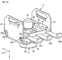
- FIG. 13A the casing 2 is inverted and set so that the upper wall 21 is on the lower side.
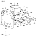
- FIG. 13B the operating portion 35 of the shaft 3 is inserted into the hole 21 a of the upper wall 21, and the shaft 3 is installed in the casing 2.
- 21c is a convex part which protrudes in the negative direction of a Z direction by four recessed parts 21b (shown in FIG. 1) provided in the upper wall 21 of the casing 2.
- the four convex portions 21c abut on the region S1 including the stopper portion 55c of the click spring 55, the region S2 including the stopper portion 55e, the region S3 of the pendulum 56, and the region S4 of the pendulum 57, respectively. Thereby, the movement of the click spring 55 in the axial direction of the shaft 3 is restricted.
- the four convex portions 21c provided in the casing 2 are an example of a movement restricting member.
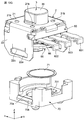
- an encoder board 60 provided with resistor patterns 61, 62, 63 and restricting members (click springs 55, pendulums 56, 57) is inserted into the end portion 36 of the shaft 3, and the casing 2 Install in.
- the protrusion 60 b of the encoder board 60 is fitted into the groove 22 b of the side wall 22 of the casing 2. Both sides in the Y direction of the encoder board 60 are sandwiched between the protruding wall 23 and the protruding piece 24 of the casing 2.
- the encoder terminals 601, 602, and 603 are not bent except for the end portions.
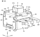
- the rotor 65 is inserted into the end portion 36 of the shaft 3 and installed in the casing 2.
- the short diameter portion 652 of the rotor 65 is passed through the locking portion 22 c of the side wall 22 of the casing 2, and the rotor 65 is assembled to the casing 2. Since the short diameter portion 652 is not locked to the locking portion 22c, the assembly of the rotor 65 to the casing 2 is facilitated.
- the operating portion 35 of the shaft 3 is operated to rotate the rotor 65, so that the long diameter portion 651 of the rotor 65 becomes the locking portion of the side wall 22 of the casing 2. 22c. Since the long diameter portion 651 is locked to the locking portion 22c by the rotation of the rotor 65, the assembled state of the rotor 65 to the casing 2 can be maintained.
- the casing 2 is inverted so that the upper wall 21 is on the upper side. At this time, since the rotor 65 is locked to the locking portion 22c of the side wall 22 of the casing 2, the rotor 65 does not fall downward.
- the conductor 71 is fitted into the recess 70a of the switch board 70 provided with the switch terminals 701, 702, 703, and the casing 2 is attached to the switch board 70 from the upper side of the switch board 70.
- the casing 2 can be attached to the switch board 70 while the conductor 71 remains fitted in the recess 70 a of the switch board 70.
- the protrusion 70 b of the switch board 70 is fitted into the hole 22 a of the side wall 22 of the casing 2, and the switch board 70 is fixed to the casing 2.
- the encoder board 60 is fixed to the hole 22a of the side wall 22 as the encoder fixing part of the casing 2
- the switch board 70 is formed of the groove part 22b of the side wall 22 as the switch fixing part of the casing 2, the protruding wall 23, and Since it is fixed to the projecting piece 24, the encoder board 60 and the switch board 70 can be integrated using the casing 2. Therefore, the bonding strength between the encoder board 60 and the switch board 70 can be improved without increasing the number of components.
- the portions of the encoder terminals 601, 602, 603 protruding from the encoder board 60 are bent, and the ends of the encoder terminals 601, 602, 603 are locked to the stepped portion 70c.
- the encoder board 60 and the switch board 70 are integrally held by the bent encoder terminals 601, 602, and 603. Accordingly, the encoder board 60 and the switch board 70 can be integrated using the encoder terminals 601, 602, and 603. Therefore, the bonding strength between the encoder board 60 and the switch board 70 can be improved without increasing the number of components.
- the rotary encoder 1 has a smooth torque fluctuation accompanying the counterclockwise rotation of the shaft 3 of the rotary encoder 1, and has a good click feeling. It was.
- the restricting members click springs 55, pendulums 56, 57
- the rotary encoder 1 can be reduced in size.
- the regulating member regulates the rotation angle of the shaft 3 by the flange portion 30 of the shaft 3
- the shaft 3 is attached to a part of the encoder mechanism 6 (for example, the rotor 65).
- the function of regulating the rotation angle is not provided. For this reason, it is not necessary to enlarge the encoder mechanism 6 (especially the rotor 65), and the rotary encoder 1 can be reduced in size.
- the click spring 55 and the pendulums 56 and 57 are plane-symmetric with respect to a plane passing through the axis 3a of the shaft 3 and along the Y direction.
- the behavior of the pendulums 56 and 57 is synchronized, so that the same is true regardless of whether the shaft 3 is rotated clockwise or counterclockwise. Click feeling can be obtained.
- each of the pendulums 56 and 57 is rotatably connected to the encoder board 60, and the other end of the pendulum 56 and 57 is a free end that contacts the convex portion 31 and the concave portion 32 of the shaft 3, and the pendulums 56 and 57 Since the click spring 55 is locked to the free end side, the free ends of the pendulums 56 and 57 are constrained to rotate on the arc, and the behavior of the pendulums 56 and 57 accompanying the rotation of the shaft 3 is stabilized. . Thereby, a smooth click feeling is obtained.
- the pendulums 56 and 57 need not be elastically deformed only by rotating with the rotation of the shaft 3, and can be formed of a rigid body such as metal. Therefore, the pendulums 56 and 57 and the shaft 3 can be made of metal to increase the strength, and the reliability can be improved.
- the pendulums 56 and 57 are attached to the shaft 3 by a click spring 55 having an elastically deformable base 55a and first and second engaging portions 55b and 55d that are engaged with the free ends of the pendulums 56 and 57. Since it is urged toward the shaft 3 side from the outside in the radial direction and comes into contact with the convex portion 31 and the concave portion 32 of the flange portion 30 from both sides of the shaft 3, a smooth click feeling is provided in any of the rotational directions of the shaft 3. It is obtained in the same way.
- the pendulums 56 and 57 are disposed in a plane symmetric position with respect to a plane passing through the axis of the shaft 3, and the convex portion 31 of the flange portion 30 of the shaft 3 is plane symmetric with respect to a plane passing through the axis of the shaft 3 And the concave portion 32 of the flange portion 30 of the shaft 3 is disposed in a plane-symmetrical position with respect to a plane passing through the axis of the shaft 3, so that the pendulums 56 and 57 have the flange portion of the shaft 3. Since the contact state with respect to the convex part 31 and the concave part 32 of the part 30 is synchronized, a smoother click feeling can be obtained.
- the click spring 55 is held on the encoder board 60 so that the entire click spring 55 can move within a predetermined range, the click spring 55 is elastically deformed so that the entire click spring 55 is bent as the shaft 3 rotates. As a result, stress concentration on the click spring 55 can be alleviated, and fatigue failure of the click spring 55 due to repeated elastic deformation can be prevented.
- the click spring 55 and the pendulums 56 and 57 of the regulating member are locked by curved surfaces (convex surfaces 111 and 112 and concave surfaces 121 and 122) that come into contact with each other.
- the contact area can be increased.
- the surface pressure decreases, so that wear on the contact surface between the contact member and the pendulums 56 and 57 can be reduced, and reliability can be improved.
- a restricting member (click spring 55, pendulum 56, 57) for restricting the rotation angle of the shaft 3, an encoder mechanism 6 for detecting the rotation direction and the rotation angle of the shaft 3, and a shaft by movement along the axis of the shaft 3 3 and a switch mechanism 7 that is pressed by 3.
- the click function of the restricting member click spring 55, pendulum 56, 57
- the encoder function of the encoder mechanism 6, and the switch function of the switch mechanism 7 can be controlled by one shaft 3.
- the three functions can be integrally controlled by the single shaft 3, and the size of the rotary encoder 1 can be reduced.
- the rotor 65 does not restrain the axial behavior of the shaft 3.
- the shaft 3 when the shaft 3 is pressed toward the switch mechanism 7 and when the shaft 3 is pushed back by the conductor 71 after the pressing, the shaft 3 slides on the hole 65a of the rotor 65 to move the rotor 65. Do not pull.
- the slider 66 is not deformed by being pressed by the resistor patterns 61, 62, and 63, and the slider 66 is separated from the resistor patterns 61, 62, and 63 to cause poor conduction. There is nothing to do.
- the regulating member (click spring 55, pendulum 56, 57) and the resistor patterns 61, 62, 63 are located on the opposite side with respect to the encoder board 60.
- the wear powder is applied to the encoder substrate 60. It is blocked and does not enter the resistor pattern 61, 62, 63 side. Accordingly, it is possible to prevent the electrical characteristics of the encoder mechanism 6 from being deteriorated by the wear powder.
- the rotary encoder has been described as an example of the rotary electronic component.
- the rotary electronic component of the present invention is not limited to the rotary encoder, and is applicable to other rotary electronic components such as a potentiometer and a trimmer capacitor. can do.
- the rotary encoder provided with the restricting member having the click spring 55 (biasing member) and the pendulums 56 and 57 (contact member) has been described.
- the restricting member includes the convex portion and the concave portion of the flange portion of the shaft.
- the present invention may be applied to a rotary electronic component including one contact member that contacts the shaft and one urging member that urges the contact member from the radially outer side of the shaft toward the shaft.
- the rotary encoder in which the click spring 55 (biasing member) and the free end sides of the pendulums 56 and 57 (contact member) are brought into contact with each other with curved surfaces and locked is described. You may make it latch on the free end side of a contact member in the state connected by the rotating shaft etc.
- the shaft 3 and the pendulums 56 and 57 are made of metal, and the click spring 55 (biasing member) is made of a resin having wear resistance. You may form with the resin which has abrasion property.
- the switch mechanism 7 is provided, but the switch mechanism may be omitted.
- the collar part is provided integrally with the shaft, the shaft may be separated from the shaft part and the collar part.
- the restriction member, the encoder mechanism, and the switch mechanism are arranged in order from the upper side to the lower side along the shaft axis.
- the restriction member, the encoder mechanism, and the switch mechanism are arranged along the shaft axis. The order may be changed.
Landscapes
- Rotary Switch, Piano Key Switch, And Lever Switch (AREA)
- Adjustable Resistors (AREA)
- Transmission And Conversion Of Sensor Element Output (AREA)
Abstract
La présente invention concerne un composant électronique rotatif (1) qui comprend un élément de base (60), un arbre (3) monté sur l'élément de base (60) de façon à pouvoir tourner de manière centrée sur un axe (3a), et des éléments de commande (55, 56, 57) pour commander l'angle de rotation de l'arbre (3). L'arbre (3) comporte une partie collier (30) contenant une pluralité de parties saillantes (31) et de parties renfoncées (32) disposées de manière alternée dans la direction périphérique. Les éléments de commande (55, 56, 57) comprennent des éléments de contact (56, 57) en contact avec les parties saillantes (31) et les parties renfoncées (32) de la partie collier (30) sur l'arbre (3), et un élément de sollicitation (55) sollicitant les éléments de contact (56, 57) dans la direction de diamètre depuis le côté externe de l'arbre (3) vers l'arbre (3).
Priority Applications (3)
| Application Number | Priority Date | Filing Date | Title |
|---|---|---|---|
| CN201780020523.4A CN108885956B (zh) | 2016-03-30 | 2017-03-09 | 旋转式电子部件 |
| JP2018508913A JP6485592B2 (ja) | 2016-03-30 | 2017-03-09 | 回転式電子部品 |
| US16/143,529 US10707035B2 (en) | 2016-03-30 | 2018-09-27 | Rotary electronic component |
Applications Claiming Priority (2)
| Application Number | Priority Date | Filing Date | Title |
|---|---|---|---|
| JP2016-069272 | 2016-03-30 | ||
| JP2016069272 | 2016-03-30 |
Related Child Applications (1)
| Application Number | Title | Priority Date | Filing Date |
|---|---|---|---|
| US16/143,529 Continuation US10707035B2 (en) | 2016-03-30 | 2018-09-27 | Rotary electronic component |
Publications (1)
| Publication Number | Publication Date |
|---|---|
| WO2017169625A1 true WO2017169625A1 (fr) | 2017-10-05 |
Family
ID=59964163
Family Applications (1)
| Application Number | Title | Priority Date | Filing Date |
|---|---|---|---|
| PCT/JP2017/009460 Ceased WO2017169625A1 (fr) | 2016-03-30 | 2017-03-09 | Composant électronique rotatif |
Country Status (5)
| Country | Link |
|---|---|
| US (1) | US10707035B2 (fr) |
| JP (1) | JP6485592B2 (fr) |
| CN (1) | CN108885956B (fr) |
| TW (1) | TWI636477B (fr) |
| WO (1) | WO2017169625A1 (fr) |
Cited By (1)
| Publication number | Priority date | Publication date | Assignee | Title |
|---|---|---|---|---|
| WO2020004147A1 (fr) * | 2018-06-25 | 2020-01-02 | 株式会社村田製作所 | Arbre rotatif pour composant électronique rotatif, procédé de fabrication d'arbre rotatif, et composant électronique rotatif |
Citations (2)
| Publication number | Priority date | Publication date | Assignee | Title |
|---|---|---|---|---|
| JP2004095242A (ja) * | 2002-08-30 | 2004-03-25 | Tsubame Musen Kk | ロータリーエンコーダ及びその基板製造方法 |
| JP2011238447A (ja) * | 2010-05-10 | 2011-11-24 | Alps Electric Co Ltd | 回転操作型入力装置 |
Family Cites Families (11)
| Publication number | Priority date | Publication date | Assignee | Title |
|---|---|---|---|---|
| JP4019515B2 (ja) * | 1998-08-21 | 2007-12-12 | 松下電器産業株式会社 | 押圧・回動操作型電子部品およびこれを用いた通信端末機器 |
| JP2001243849A (ja) * | 2000-03-01 | 2001-09-07 | Alps Electric Co Ltd | 回転型電気部品のクリック構造 |
| JP2003007173A (ja) * | 2001-06-25 | 2003-01-10 | Alps Electric Co Ltd | 複合操作型電気部品 |
| CN201000845Y (zh) * | 2006-07-14 | 2008-01-02 | 富士康(昆山)电脑接插件有限公司 | 多方向开关 |
| JP2008203037A (ja) * | 2007-02-19 | 2008-09-04 | Seiko Instruments Inc | 電子時計の押圧型スイッチ用ばね構造体及び押圧型スイッチ並びにこれを備えた電子時計 |
| JP4553945B2 (ja) * | 2008-01-21 | 2010-09-29 | ホシデン株式会社 | 多方向スイッチ |
| TWM396479U (en) * | 2010-07-28 | 2011-01-11 | Biwin Technologies Co Ltd | Position limiting structure of turn switch |
| TWM409422U (en) * | 2011-01-06 | 2011-08-11 | Forward Electronics Co Ltd | Encoder with three-color LED's |
| JP5615217B2 (ja) * | 2011-03-23 | 2014-10-29 | マルホン工業株式会社 | 遊技機 |
| CN204045500U (zh) * | 2014-08-25 | 2014-12-24 | 李卫泽 | 机械式旋转数显电子定时器 |
| CN204497115U (zh) * | 2015-04-29 | 2015-07-22 | 浙江中讯电子有限公司 | 一种旋钮开关用防转机构 |
-
2017
- 2017-03-09 WO PCT/JP2017/009460 patent/WO2017169625A1/fr not_active Ceased
- 2017-03-09 JP JP2018508913A patent/JP6485592B2/ja active Active
- 2017-03-09 CN CN201780020523.4A patent/CN108885956B/zh active Active
- 2017-03-15 TW TW106108465A patent/TWI636477B/zh active
-
2018
- 2018-09-27 US US16/143,529 patent/US10707035B2/en active Active
Patent Citations (2)
| Publication number | Priority date | Publication date | Assignee | Title |
|---|---|---|---|---|
| JP2004095242A (ja) * | 2002-08-30 | 2004-03-25 | Tsubame Musen Kk | ロータリーエンコーダ及びその基板製造方法 |
| JP2011238447A (ja) * | 2010-05-10 | 2011-11-24 | Alps Electric Co Ltd | 回転操作型入力装置 |
Cited By (1)
| Publication number | Priority date | Publication date | Assignee | Title |
|---|---|---|---|---|
| WO2020004147A1 (fr) * | 2018-06-25 | 2020-01-02 | 株式会社村田製作所 | Arbre rotatif pour composant électronique rotatif, procédé de fabrication d'arbre rotatif, et composant électronique rotatif |
Also Published As
| Publication number | Publication date |
|---|---|
| JPWO2017169625A1 (ja) | 2019-02-07 |
| TW201737281A (zh) | 2017-10-16 |
| CN108885956B (zh) | 2020-03-24 |
| US10707035B2 (en) | 2020-07-07 |
| JP6485592B2 (ja) | 2019-03-20 |
| TWI636477B (zh) | 2018-09-21 |
| US20190035576A1 (en) | 2019-01-31 |
| CN108885956A (zh) | 2018-11-23 |
Similar Documents
| Publication | Publication Date | Title |
|---|---|---|
| JP6447715B2 (ja) | 回転式電子部品および回転エンコーダ | |
| TWI469174B (zh) | Electrical parts of the detent mechanism | |
| US8440928B2 (en) | Rotary electronic component | |
| JP6485592B2 (ja) | 回転式電子部品 | |
| JP2005259634A (ja) | 回転型電気部品 | |
| JP2017091603A (ja) | 回転エンコーダ | |
| JP6406434B2 (ja) | 回転エンコーダ | |
| JP6406435B2 (ja) | 回転式電子部品および回転エンコーダ | |
| JP4583743B2 (ja) | クリック機構付き回転型可変抵抗器 | |
| KR100803959B1 (ko) | 회전형 전기 부품 | |
| JP2020071059A (ja) | 回転操作部品、回転検知機構および携帯装置 | |
| JP2008152966A (ja) | 回転体復帰機構 | |
| TW201340154A (zh) | 電子零件的掣子機構 | |
| JP4283159B2 (ja) | 回転型可変抵抗器 | |
| WO2020004147A1 (fr) | Arbre rotatif pour composant électronique rotatif, procédé de fabrication d'arbre rotatif, et composant électronique rotatif | |
| JP2008159907A (ja) | 回転式電子部品 | |
| WO2019087607A1 (fr) | Dispositif d'entrée | |
| JP2005116411A (ja) | スイッチ装置 |
Legal Events
| Date | Code | Title | Description |
|---|---|---|---|
| WWE | Wipo information: entry into national phase |
Ref document number: 2018508913 Country of ref document: JP |
|
| NENP | Non-entry into the national phase |
Ref country code: DE |
|
| 121 | Ep: the epo has been informed by wipo that ep was designated in this application |
Ref document number: 17774170 Country of ref document: EP Kind code of ref document: A1 |
|
| 122 | Ep: pct application non-entry in european phase |
Ref document number: 17774170 Country of ref document: EP Kind code of ref document: A1 |