WO2017169657A1 - 電動アクチュエータ - Google Patents
電動アクチュエータ Download PDFInfo
- Publication number
- WO2017169657A1 WO2017169657A1 PCT/JP2017/009706 JP2017009706W WO2017169657A1 WO 2017169657 A1 WO2017169657 A1 WO 2017169657A1 JP 2017009706 W JP2017009706 W JP 2017009706W WO 2017169657 A1 WO2017169657 A1 WO 2017169657A1
- Authority
- WO
- WIPO (PCT)
- Prior art keywords
- electric actuator
- rotor
- axial direction
- motor
- nut member
- Prior art date
- Legal status (The legal status is an assumption and is not a legal conclusion. Google has not performed a legal analysis and makes no representation as to the accuracy of the status listed.)
- Ceased
Links
Images



Classifications
-
- F—MECHANICAL ENGINEERING; LIGHTING; HEATING; WEAPONS; BLASTING
- F16—ENGINEERING ELEMENTS AND UNITS; GENERAL MEASURES FOR PRODUCING AND MAINTAINING EFFECTIVE FUNCTIONING OF MACHINES OR INSTALLATIONS; THERMAL INSULATION IN GENERAL
- F16H—GEARING
- F16H25/00—Gearings comprising primarily only cams, cam-followers and screw-and-nut mechanisms
- F16H25/18—Gearings comprising primarily only cams, cam-followers and screw-and-nut mechanisms for conveying or interconverting oscillating or reciprocating motions
- F16H25/20—Screw mechanisms
-
- F—MECHANICAL ENGINEERING; LIGHTING; HEATING; WEAPONS; BLASTING
- F16—ENGINEERING ELEMENTS AND UNITS; GENERAL MEASURES FOR PRODUCING AND MAINTAINING EFFECTIVE FUNCTIONING OF MACHINES OR INSTALLATIONS; THERMAL INSULATION IN GENERAL
- F16H—GEARING
- F16H25/00—Gearings comprising primarily only cams, cam-followers and screw-and-nut mechanisms
- F16H25/18—Gearings comprising primarily only cams, cam-followers and screw-and-nut mechanisms for conveying or interconverting oscillating or reciprocating motions
- F16H25/20—Screw mechanisms
- F16H25/2015—Means specially adapted for stopping actuators in the end position; Position sensing means
-
- F—MECHANICAL ENGINEERING; LIGHTING; HEATING; WEAPONS; BLASTING
- F16—ENGINEERING ELEMENTS AND UNITS; GENERAL MEASURES FOR PRODUCING AND MAINTAINING EFFECTIVE FUNCTIONING OF MACHINES OR INSTALLATIONS; THERMAL INSULATION IN GENERAL
- F16H—GEARING
- F16H25/00—Gearings comprising primarily only cams, cam-followers and screw-and-nut mechanisms
- F16H25/18—Gearings comprising primarily only cams, cam-followers and screw-and-nut mechanisms for conveying or interconverting oscillating or reciprocating motions
- F16H25/20—Screw mechanisms
- F16H25/205—Screw mechanisms comprising alternate power paths, e.g. for fail safe back-up
-
- H—ELECTRICITY
- H02—GENERATION; CONVERSION OR DISTRIBUTION OF ELECTRIC POWER
- H02K—DYNAMO-ELECTRIC MACHINES
- H02K11/00—Structural association of dynamo-electric machines with electric components or with devices for shielding, monitoring or protection
- H02K11/20—Structural association of dynamo-electric machines with electric components or with devices for shielding, monitoring or protection for measuring, monitoring, testing, protecting or switching
- H02K11/21—Devices for sensing speed or position, or actuated thereby
-
- H—ELECTRICITY
- H02—GENERATION; CONVERSION OR DISTRIBUTION OF ELECTRIC POWER
- H02K—DYNAMO-ELECTRIC MACHINES
- H02K11/00—Structural association of dynamo-electric machines with electric components or with devices for shielding, monitoring or protection
- H02K11/30—Structural association with control circuits or drive circuits
- H02K11/33—Drive circuits, e.g. power electronics
-
- H—ELECTRICITY
- H02—GENERATION; CONVERSION OR DISTRIBUTION OF ELECTRIC POWER
- H02K—DYNAMO-ELECTRIC MACHINES
- H02K5/00—Casings; Enclosures; Supports
- H02K5/04—Casings or enclosures characterised by the shape, form or construction thereof
- H02K5/22—Auxiliary parts of casings not covered by groups H02K5/06-H02K5/20, e.g. shaped to form connection boxes or terminal boxes
-
- H—ELECTRICITY
- H02—GENERATION; CONVERSION OR DISTRIBUTION OF ELECTRIC POWER
- H02K—DYNAMO-ELECTRIC MACHINES
- H02K7/00—Arrangements for handling mechanical energy structurally associated with dynamo-electric machines, e.g. structural association with mechanical driving motors or auxiliary dynamo-electric machines
- H02K7/06—Means for converting reciprocating motion into rotary motion or vice versa
-
- F—MECHANICAL ENGINEERING; LIGHTING; HEATING; WEAPONS; BLASTING
- F16—ENGINEERING ELEMENTS AND UNITS; GENERAL MEASURES FOR PRODUCING AND MAINTAINING EFFECTIVE FUNCTIONING OF MACHINES OR INSTALLATIONS; THERMAL INSULATION IN GENERAL
- F16H—GEARING
- F16H25/00—Gearings comprising primarily only cams, cam-followers and screw-and-nut mechanisms
- F16H25/18—Gearings comprising primarily only cams, cam-followers and screw-and-nut mechanisms for conveying or interconverting oscillating or reciprocating motions
- F16H25/20—Screw mechanisms
- F16H2025/2031—Actuator casings
-
- F—MECHANICAL ENGINEERING; LIGHTING; HEATING; WEAPONS; BLASTING
- F16—ENGINEERING ELEMENTS AND UNITS; GENERAL MEASURES FOR PRODUCING AND MAINTAINING EFFECTIVE FUNCTIONING OF MACHINES OR INSTALLATIONS; THERMAL INSULATION IN GENERAL
- F16H—GEARING
- F16H25/00—Gearings comprising primarily only cams, cam-followers and screw-and-nut mechanisms
- F16H25/18—Gearings comprising primarily only cams, cam-followers and screw-and-nut mechanisms for conveying or interconverting oscillating or reciprocating motions
- F16H25/20—Screw mechanisms
- F16H2025/2062—Arrangements for driving the actuator
- F16H2025/2075—Coaxial drive motors
Definitions
- the present invention relates to an electric actuator.
- Patent Document 1 mentions how to construct the power feeding circuit. It has not been. For example, when a power supply circuit is constructed every time an electric actuator is assembled, the assembling property (productivity) of the electric actuator is poor, and the electric actuator becomes expensive.
- the main object of the present invention is to provide an electric actuator excellent in assemblability.
- the present invention which has been devised to solve the above problems, includes a motor unit that is driven by receiving power supply, a motion conversion mechanism unit that converts the rotational motion of the motor unit into a linear motion, and outputs the motor unit,
- a housing housing the motion conversion mechanism, and the motion conversion mechanism includes a screw shaft disposed coaxially with the rotation center of the rotor of the motor unit, and a nut member rotatably fitted on the outer periphery thereof.
- An electric actuator in which the screw shaft linearly moves in the axial direction as the nut member rotates in response to the rotational movement of the rotor, and the housing is composed of a plurality of members coupled in the axial direction.
- the terminal portion holding a power supply circuit for supplying electric power has a cylindrical portion sandwiched from both sides in the axial direction by structural members of the housing.
- the members constituting the casing can be coupled in the axial direction, and the driving power can be supplied to the motor unit simply by assembling the casing. For this reason, it is possible to improve the assembly (productivity) of the electric actuator and reduce the cost of the electric actuator.
- stator of the motor part can be fitted to the inner periphery of the cylindrical part of the terminal part.
- stator of the motor unit can be assembled to the inner periphery of the casing at the same time as the casing is assembled, the assembly of the electric actuator can be further enhanced.
- the terminal part can also hold a rotation angle detection sensor for detecting the rotation angle of the rotor. If such a sensor is provided, it is possible to detect the rotation angle (rotation amount) of the rotor and control the movement amount of the screw shaft in the axial direction based on the detected value. Therefore, it is possible to easily realize an electric actuator excellent in operation accuracy of the screw shaft (output member).
- the cylindrical part of the terminal part can be provided with an opening for communicating the inside and outside of the housing.
- the lead wire connected to the power supply circuit (which constitutes the power supply circuit), and further the signal wire connected to the rotation angle detection sensor is connected to the radial direction of the housing through the opening. Can be pulled out.
- the terminal unit can be shared as long as the shape of the coupled part of the coupling partner member of the terminal unit is the same. As a result, it is possible to easily cope with the development of various types (series) of electric actuators by sharing parts and members.
- the rotor may have a hollow rotary shaft that is rotatably supported by rolling bearings that are arranged at two locations spaced apart in the axial direction, with the nut member disposed on the inner periphery.
- the hollow rotary shaft may be provided with the inner raceway surface of one of the two rolling bearings.
- the electric actuator can be made more compact in the axial direction by arranging the inner raceway surface inside the axial width of the nut member.
- the motion conversion mechanism may have a speed reducer that decelerates the rotation of the rotor and transmits it to the nut member.
- a planetary gear speed reducer can be adopted as the speed reducer. If it is a planetary gear reducer, the reduction ratio can be easily adjusted by changing the gear specifications or changing the number of installation stages of the planetary gear, and even if the planetary gears are installed in multiple stages. There is an advantage that it is possible to avoid an increase in the size of the speed reducer and consequently the electric actuator.
- an electric actuator excellent in assemblability can be provided.
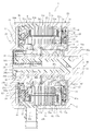
- FIG. 1 is a longitudinal sectional view of an electric actuator according to an embodiment of the present invention.
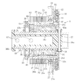
- FIG. 2 is a cross-sectional view taken along line EE in FIG. 1. It is the longitudinal cross-sectional view which took out the rotor and motion conversion mechanism part of the motor, and was expanded.
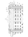
- FIG. 5 is a cross-sectional view taken along line FF in FIG. 1. It is a longitudinal cross-sectional view which shows the state which integrated the ring gear in the casing. It is the longitudinal cross-sectional view which took out the stator and terminal part of the motor, and was expanded.
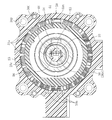
- FIG. 2 is a cross-sectional view taken along line GG in FIG. 1.
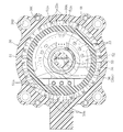
- FIG. 2 is a cross-sectional view taken along line HH in FIG. 1.
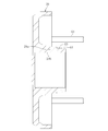
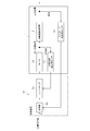
- FIG. 10 is a cross-sectional view taken along the line II in FIG. 9. It is a schematic block diagram which shows the control system of the electric actuator of FIG. It is a schematic block diagram which shows the control system of the electric actuator which concerns on other embodiment of this invention.
- FIG. 1 is a longitudinal sectional view of an electric actuator according to an embodiment of the present invention
- FIG. 2 is a sectional view taken along line EE in FIG. 1
- FIG. The longitudinal cross-sectional view which took out the mechanism part and expanded (vertical cross-sectional view of the subassembly formed by assembling the rotor and the motion conversion mechanism part) is shown.
- 1 and 2 show a state where the screw shaft 33 constituting the output member of the electric actuator is located at the origin.
- the “state positioned at the origin” means that the end surface of the screw shaft 33 (the inner member 36 connected thereto) is opposed to the end surface of the cover 29 by the spring force of the compression coil spring 48 described later. It is the state which exists in the position which contact
- the electric actuator 1 of the present embodiment includes a motor unit A that is driven by power supply, and a motion conversion that converts the rotational motion of the motor unit A into a linear motion and outputs it.
- a mechanism part B, an operation part C for operating an operation target not shown, and a terminal part D are provided, and these are accommodated and held in the housing 2.
- the housing 2 is composed of a plurality of members that are coaxially arranged and coupled in the axial direction.
- the housing 2 of this embodiment is formed of a metal material (for example, an aluminum alloy, a zinc alloy, or a magnesium alloy) that is excellent in workability and thermal conductivity, and is one side in the axial direction (the right side in FIG. 1 and FIG. 2). The same applies hereinafter.) And the other end in the axial direction (the left side of the paper in FIGS.
- the cylindrical casing 20 having an open end, and the other end in the axial direction of the casing 20 It consists of a combined body of a cover 29 that closes the opening of the part and a terminal main body 50 (a cylindrical part 50A thereof) that is arranged between the casing 20 and the cover 29 and constitutes the terminal part D.
- the cover 29 and the terminal main body 50 are fixedly attached to the casing 20 by assembly bolts 61 shown in FIGS. Accordingly, the terminal main body 50 has a cylindrical portion 50A that is sandwiched and fixed between the casing 20 and the cover 29 arranged on both sides in the axial direction.
- the motor part A includes a stator 23 fitted and fixed to the inner peripheral surface of the cylindrical part 50A of the casing 20 and the terminal main body 50, and a rotor 24 arranged to face the inner periphery of the stator 23 via a radial gap.
- a radial gap type motor (specifically, a three-phase brushless motor having a U phase, a V phase, and a W phase) 25 is provided.
- the stator 23 includes an insulating bobbin 23b attached to the stator core 23a, and a coil 23c wound around the bobbin 23b.
- the rotor 24 includes a rotor core 24a, a permanent magnet 24b as a rotor magnet attached to the outer periphery of the rotor core 24a, and a rotor inner 26 as a hollow rotating shaft that is formed in a hollow shape and has the rotor core 24a attached to the outer periphery.
- the rotor core 24 a is fitted to the outer peripheral surface 26 b of the rotor inner 26 after setting the side plate 65 on the shoulder portion 26 a on one axial side of the rotor inner 26.
- the permanent magnet 24b (see FIG. 2) is fitted to the outer periphery of the rotor core 24a, the side plate 65 attached to the axially outer side of the other end of the rotor core 24a in the axial direction of the rotor inner 26, and its It is positioned and fixed by a circlip 66 attached to the outside in the axial direction.
- an inner raceway surface 27 a of the rolling bearing 27 is formed on the outer periphery of one end of the rotor inner 26 in the axial direction, and the outer ring 27 b of the rolling bearing 27 is fixed to the inner peripheral surface of the casing 20.
- the bearing holder 28 is attached to the inner peripheral surface.
- a rolling bearing 30 is mounted between the inner peripheral surface of the other end in the axial direction of the rotor inner 26 and the outer peripheral surface of the cylindrical portion 29 a of the cover 29.
- the motion conversion mechanism section B of the present embodiment includes a ball screw device 31 and a planetary gear speed reducer 10 as a speed reducer.
- the planetary gear speed reducer 10 includes a motor section A. Are arranged adjacent to each other in the axial direction.
- the ball screw device 31 is arranged coaxially with the rotation center of the rotor 24 and is rotatably fitted to the outer periphery of the screw shaft 33 via a plurality of balls 34 and a screw shaft 33 constituting an output member of the electric actuator 1.
- the nut member 32 disposed on the inner periphery of the rotor inner 26 and the top 35 as a circulation member are provided.
- a plurality of balls 34 are loaded between the spiral groove 32a formed on the inner peripheral surface of the nut member 32 and the spiral groove 33a formed on the outer peripheral surface of the screw shaft 33, and the top 35 is incorporated. .
- the screw shaft 33 is formed in a hollow shape having a hole portion 33b extending in the axial direction (in this embodiment, through holes opened on both end surfaces in the axial direction) 33b, and the inner member 36 is accommodated in the hole portion 33b.
- the inner member 36 is made of, for example, a resin material such as PPS, and has a circular solid portion 36a provided at an end portion on one side in the axial direction, a flange portion 36b provided at an end portion on the other side in the axial direction, It has integrally the cylinder part 36c which connects both parts 36a and 36b.
- the inner member 36 accommodated in the hole 33b of the screw shaft 33 is connected and fixed to the screw shaft 33 by fitting a pin 37 so as to penetrate the circular solid portion 36a and the screw shaft 33 in the radial direction.
- the Both end portions of the pin 37 protrude radially outward from the outer peripheral surface of the screw shaft 33, and a guide collar 38 is rotatably fitted on the protruding portion.
- the guide collar 38 is formed of a resin material such as PPS, for example, and is fitted in an axial guide groove 20b (see also FIG. 5) provided on the inner peripheral surface of the small diameter cylindrical portion 20a of the casing 20.
- an actuator head 39 as an operation portion C is detachably attached to one end of the screw shaft 33 in the axial direction.
- the actuator head 39 of this embodiment is a so-called push type in which the tip surface pressurizes the operation target in the axial direction as the screw shaft 33 linearly moves in one axial direction.
- a so-called push-pull type that can operate the operation target on both sides in the axial direction can be adopted.
- the type and shape of the actuator head 39 to be used is determined in consideration of the equipment used (the shape and operation mode of the operation target) on which the electric actuator 1 is mounted.
- the planetary gear speed reducer 10 includes a ring gear 40 fixed to the casing 20, a sun gear 41 press-fitted to the inner circumferential surface 26c of the rotor inner 26, and the ring gear 40 and the sun gear 41.
- a plurality (four in this embodiment) of planetary gears 42 arranged between the two gears 40 and 41, and a planetary gear carrier 43 and a planetary gear holder 44 that rotatably hold the planetary gears 42 are provided.
- the planetary gear carrier 43 takes out the revolution movement of the planetary gear 42 and outputs it. Accordingly, the planetary gear carrier 43 constitutes an output member of the planetary gear reducer 10.
- the outer periphery of the ring gear 40 is provided with notches 40 a projecting radially outward at a plurality of locations (four locations in the illustrated example) spaced apart in the circumferential direction.
- the grooves are fitted in axial grooves 20e (see also FIG. 5) provided at a plurality of locations (four locations in the illustrated example) separated in the circumferential direction of the surface 20c.
- the planetary gear carrier 43 includes a pin-like portion fitted on the inner periphery of the planetary gear 42, a disc-like portion arranged on one side in the axial direction of the planetary gear 42, and a disc A cylindrical portion 43 a that extends from the radially inner end of the shape portion to the other axial side and is interposed between the inner peripheral surface 26 d of the rotor inner 26 and the outer peripheral surface 32 b of the nut member 32 is integrally provided.
- the planetary gear carrier 43 is rotatable relative to the rotor inner 26, and is connected to the nut member 32 of the ball screw device 31 so as to be integrally rotatable.
- the outer peripheral surface of the cylindrical portion 43 a faces the inner peripheral surface 26 d of the rotor inner 26 (and the inner peripheral surface of the sun gear 41) via a radial gap, and the inner peripheral surface of the cylindrical portion 43 a is the nut member 32. It is press-fitted and fixed to the outer peripheral surface 32b.
- the connection workability during assembly is good. In addition to the above, stable torque transmission is possible even for high torque after deceleration. Further, since the sun gear 41 is press-fitted into the stepped inner peripheral surface 26c of the rotor inner 26, the rotor inner 26 and the sun gear 41 are connected so as to be able to transmit torque. Also in this respect, the connection workability during assembly is good. is there.
- the sun gear 41 only needs to be able to rotate integrally with the rotor inner 26 before deceleration, and therefore the torque transmission performance required between the two can be sufficiently ensured. Furthermore, since the rotor inner 26 and the sun gear 41 are connected at a position directly below the rolling bearing 27 that supports the rotor inner 26, the rotational accuracy of the sun gear 41 is also good.
- the planetary gear reducer 10 having the above configuration, the rotational motion of the rotor 24 of the motor 25 is transmitted to the nut member 32 after being decelerated. Thereby, since a rotational torque can be increased, the small motor 25 can be employ
- a thrust washer 45 is disposed between the end face on one axial side of the nut member 32 and the casing 20, and the thrust attached to the outer periphery of the distal end portion of the cylindrical portion 29 a of the cover 29.
- a needle roller bearing 47 as a thrust bearing is disposed between the receiving ring 46 and the end surface on the other axial side of the nut member 32.
- a compression coil spring 48 is disposed between the inner peripheral surface 29b of the cylindrical portion 29a of the cover 29 and the outer peripheral surface of the screw shaft 33.
- the ends of the compression coil spring 48 on one side and the other side in the axial direction are in contact with the needle roller bearing 47 and the flange portion 36b of the screw shaft 33 (the inner member 36 connected to the screw shaft 33).
- the screw shaft 33 is constantly urged toward the origin by the spring force of the compression coil spring 48 provided in the above manner. In this way, for example, when the drive power is not properly supplied to the motor 25, the screw shaft 33 is automatically returned to the origin, and the possibility of adversely affecting the operation of the operation target (not shown) is possible. Can be reduced. Further, if the compression coil spring 48 is provided in the above-described manner, an axial pressure can be applied to the nut member 32. Thereby, the response delay resulting from the operation gap provided between the nut member 32 and the screw shaft 33 can be eliminated, and the operability of the screw shaft 33 can be enhanced.
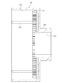
- FIG. 9 is a left side view of FIG. 1, and FIG. 10 is a cross-sectional view taken along the line II in FIG.
- the cover 29 is formed of a metal material excellent in workability and thermal conductivity, for example, an aluminum alloy, a zinc alloy, or a magnesium alloy.
- a cooling fin for increasing the cooling efficiency of the electric actuator 1 may be provided on the outer surface of the cover 29.
- a bearing mounting surface 63 on which the rolling bearing 30 is mounted and a fitting surface 64 on which the thrust receiving ring 46 is fitted are provided on the outer peripheral surface of the cylindrical portion 29 a of the cover 29. Yes.
- a through hole (not shown) through which the assembly bolt 61 of the electric actuator 1 is inserted and a mounting bolt for attaching the electric actuator 1 to a device to be used are inserted into the cover 29.
- a through hole 62 is provided.
- FIG. 1 is a cross-sectional view taken along line GG in FIG. 1
- FIG. 8 is a cross-sectional view taken along line HH in FIG.
- the terminal portion D is formed of a resin material such as PPS, for example, and includes a cylindrical portion 50A that constitutes a part of the housing 2 and the other axial side of the cylindrical portion 50A.
- a terminal main body 50 integrally including a disk-shaped portion 50B extending radially inward from the end portion, a bus bar 51 and a disk-shaped printed circuit board 52 screwed to the terminal main body 50 (the disk-shaped portion 50B).
- the terminal main body 50 (the cylindrical portion 50A) is provided for attaching the through-hole 50C through which the assembly bolt 61 shown in FIGS. Through holes 50D through which the bolts are inserted, and are sandwiched between the casing 20 and the cover 29 by the assembly bolts 61 (see FIGS. 1 and 2).
- the terminal part D (terminal body 50) collectively holds electric parts such as a power supply circuit for supplying driving power to the motor 25 and sensors described later.
- the power feeding circuit connects the coils 23c of the stator 23 to the terminals 51a of the bus bar 51 for each of the U phase, the V phase, and the W phase.
- the terminal 51 b of 51 and the terminal block 50 a of the terminal body 50 are fastened with screws 70.
- the terminal block 50a has a terminal 50b to which a lead wire (not shown) is connected.
- the lead wire is an opening provided in the cylindrical portion 50A of the terminal body 50 so as to communicate the inside and outside of the housing 2. It is pulled out to the outer diameter side of the housing 2 through 50c (see FIG. 1) and connected to the controller 81 (see FIG. 11) of the control device 80.
- the electric actuator 1 of this embodiment is equipped with two types of sensors, and these two types of sensors are held by the terminal body 50.
- one of the two types of sensors is a rotation angle detection sensor 53 used for rotation control of the motor 25, and the other is stroke control (detection of displacement in the axial direction) of the screw shaft 33.
- This is a stroke detection sensor 55 used for As the rotation angle detection sensor 53 and the stroke detection sensor 55, a Hall sensor which is a kind of magnetic sensor is used.
- the rotation angle detection sensor 53 is attached to a printed circuit board 52, and via a pulsar ring 54 attached to an end on the other axial side of the rotor inner 26 and an axial clearance. Opposed.
- the rotation angle detection sensor 53 determines the timing for supplying current to each of the U phase, V phase, and W phase of the motor 25.
- the stroke detection sensor 55 is attached to a belt-like printed board 56 that extends in the axial direction and has an end on the other side in the axial direction connected to the printed board 52. .
- the printed circuit board 56 and the stroke detection sensor 55 are disposed on the inner periphery of the hole 33b of the screw shaft 33, more specifically, on the inner periphery of the cylindrical portion 36c of the inner member 36 accommodated in the hole 33b.
- a permanent magnet 57 as a target is attached to the inner periphery of the cylindrical portion 36c of the inner member 36 so as to face the stroke detection sensor 55 via a radial gap. Permanent magnets 57 are attached to two locations separated from each other.
- the stroke detection sensor 55 detects the axial and radial magnetic fields formed around the permanent magnet 57, and calculates the axial displacement amount of the screw shaft 33 based on this.
- the signal line connected to the rotation angle detection sensor 53 and the signal line connected to the stroke detection sensor 55 are both provided in the cylindrical portion 50A of the terminal body 50. It is pulled out to the outer diameter side of the housing 2 through the opening 50c (see FIG. 1) and connected to the control device 80 (see FIG. 11).
- the ring gear 40 is assembled in the casing 20.
- the rotor 24 of the motor 25 and the subassembly of the motion conversion mechanism B shown in FIG. 3 are inserted into the casing 20.
- the planetary gear 42 and the ring gear 40 are engaged with each other, the guide collar 38 is fitted into the guide groove 20 b of the casing 20, and the bearing holder 28 is fitted into the inner peripheral surface 20 c of the casing 20.
- the stator 23 is fitted to the inner periphery of the casing 20 in the subassembly of the stator 23 and the terminal portion D (terminal body 50) of the motor 25 shown in FIG. Are fastened by an assembly bolt 61 (see FIGS. 9 and 10). Thereby, the electric actuator 1 is completed.
- the operation mode of the electric actuator 1 having the above configuration will be briefly described with reference to FIGS.
- the ECU calculates a required position command value based on the operation amount.
- the position command value is sent to the controller 81 of the control device 80, which calculates a motor rotation angle control signal necessary for the position command value and sends this control signal to the motor 25.
- the screw shaft 33 linearly moves (advances) to one side in the axial direction while being prevented from rotating. At this time, the screw shaft 33 moves forward to a position based on the control signal of the controller 81, and the actuator head 39 fixed to the end portion on the one axial side of the screw shaft 33 operates (pressurizes) an operation target (not shown).
- the axial position of the screw shaft 33 (the amount of axial displacement) is directly detected by the stroke detection sensor 55 as shown in FIG. 11, and the detection signal is sent to the comparison unit 82 of the control device 80.
- the comparison unit 82 calculates the difference between the detection value detected by the stroke detection sensor 55 and the position command value, and the controller 81 is based on the calculated value and the signal sent from the rotation angle detection sensor 53. Send a control signal to.
- the axial position of the screw shaft 33 (actuator head 39) is feedback-controlled. For this reason, when the electric actuator 1 of this embodiment is applied to, for example, shift-by-wire, the shift position can be reliably controlled.
- the electric power for driving the motor 25, the sensors 53, 55, and the like is supplied from an external power source (not shown) such as a battery provided in the vehicle via a control device 80 and a power supply circuit held in the terminal portion D. To the motor 25 and the like.
- the electric actuator 1 of the present embodiment in addition to the power supply circuit for supplying driving power to the motor 25, the rotation angle detection sensor 53 and screw for detecting the rotation angle of the rotor 24 of the motor 25.
- a terminal portion D (terminal body 50) holding electrical components such as a stroke detection sensor 55 for detecting the amount of movement of the shaft 33 in the axial direction is provided on both sides in the axial direction by the casing 20 and the cover 29 constituting the housing 2.
- the cylindrical portion 50A is sandwiched between the two.
- the electric actuator 1 according to the present embodiment employs a sandwich structure in which the terminal main body 50 holding the electric components including the power feeding circuit is held in the axial direction between the casing 29 and the cover 29.
- a part of the stator 23 of the motor 25 (the outer periphery on the other end in the axial direction) is located on the inner periphery of the cylindrical portion 50 ⁇ / b> A of the terminal body 50. It is mated.
- the stator 23 can be assembled to the inner periphery of the housing 2 at the same time as the housing 2 is assembled, the assembling property of the electric actuator 1 is also improved from this point.
- the cylindrical portion 50A of the terminal body 50 has an opening 50c that allows the inside and outside of the housing 2 to communicate with each other.
- the lead wire connected to the power feeding circuit and the signal wire (electrical) connected to the sensors 53 and 55 described above. Wiring) is drawn out radially outward of the housing 2 through the opening 50c.
- the terminal body 50 alone, that is, the electrical system necessary for operating the electric actuator 1 appropriately and accurately is the housing 2 (electric actuator 1).
- the connection partner of the terminal body 50 The terminal body 50 can be shared as long as the members (here, the casing 20 in particular) have the same coupled portion shape. As a result, it is possible to easily cope with the development of various types (series) of electric actuators 1 by sharing parts and members.
- the motor unit A (motor 25) is downsized by providing the planetary gear speed reducer 10 in the motion conversion mechanism unit B, and the rotor inner 26, the cylindrical part 43a of the planetary gear carrier 43, and the nut member 32 in the radial direction Combined with the superposition structure, the radial dimension M (see FIG. 1) of the housing 2 of the electric actuator 1 can be reduced.
- the rotor inner 26 as a hollow rotating shaft has an inner raceway surface 27a of a rolling bearing 27 disposed in the vicinity of one end of the rotor core 24a in the axial direction, and this rolling bearing 27 causes one side of the rotor inner 26 in the axial direction.
- the end of is rotatably supported.
- the rotor inner 26 can be made compact in the axial direction.
- the structure in which the rolling bearing 27 is arranged inside the axial width of the nut member 32 is combined to reduce the axial dimension L (see FIG. 1) of the housing 2 of the electric actuator 1. Can do. As described above, if the axial dimension L and the radial dimension M of the housing 2 can be shortened, the electric actuator 1 can be made compact as a whole. Can be realized.
- the screw shaft 33 is formed in a hollow shape, and a stroke detection sensor 55 for directly detecting the axial displacement amount of the screw shaft 33 is disposed on the inner periphery of the screw shaft 33.
- the installation space for the stroke detection sensor 55 does not have to be provided separately on the outside in the axial direction of the motor part A, etc., so that the electric actuator is compact in the axial direction and excellent in the operation accuracy of the screw shaft 33. 1 can be realized.
- the rolling bearings 27 and 30 that support the rotor inner 26 may support a radial load about the weight of the rotor 24.
- the rotor inner 26 integrally including the inner raceway surface 27a of the rolling bearing 27 does not need to be formed of a high-strength material.
- the rotor inner 26 may be formed of an inexpensive mild steel material in which heat treatment such as quenching and tempering is omitted. Necessary strength can be ensured.
- the electric actuator 1 of the present embodiment since the rotational motion of the motor 25 is transmitted to the nut member 32 via the planetary gear speed reducer 10, no radial load is generated, and the linear motion of the screw shaft 33 is not caused.
- the accompanying reaction force (thrust load) is directly supported by the needle roller bearing 47 disposed adjacent to the other axial side of the nut member 32. Accordingly, since the rolling bearing 27 only needs to have a radial positioning function, the rotor inner 26 integrally including the inner raceway surface 27a of the rolling bearing 27 is sufficient for the material specifications as described above. Thereby, the cost of the electric actuator 1 can be reduced.
- the thrust load acting on the nut member 32 is directly supported by the needle roller bearing 47, the ball screw device 31 (motion converting mechanism portion B) and further the motor portion A are supported. It is possible to effectively suppress the moment load from acting on the rotor 24.
- the needle roller bearing 47 is disposed within the axial range between the rolling bearings 27 and 30 as in this embodiment, the effect of suppressing the moment load can be enhanced. If the moment load can be suppressed in this way, the operation accuracy and durability of the output member of the electric actuator 1 can be increased, and a small needle roller bearing 47 can be used.
- the needle roller bearing 47 is disposed near the center in the axial direction between the rolling bearings 27 and 30, and in this case, the effect of suppressing the moment load can be further enhanced. For this reason, the miniaturization of the needle roller bearing 47 can be further promoted. As a result, extremely small ones can be employed as the needle roller bearing 47, the thrust receiving ring 46, and the like, so that the electric actuator 1 can be prevented from being elongated in the axial direction as much as possible.
- the two electric actuators 1 (units of the motor part A, the motion conversion mechanism part B and the terminal part D) are arranged in the axial direction.
- An electric actuator capable of individually operating two operation objects can also be realized.
- Such an electric actuator can be preferably mounted on, for example, a DCT (Dual Clutch Transmission) which is a kind of automatic transmission, and can contribute to the compactness of the entire DCT.
- a DCT Direct Clutch Transmission
- the electric actuator 1 according to the embodiment of the present invention has been described above, but the embodiment of the present invention is not limited to this.
- the ball screw device 31 is employed for the motion converting mechanism B, but a so-called sliding screw device in which the ball 34 and the top 35 are omitted is employed for the motion converting mechanism B.
- the present invention can also be applied to an electric actuator.
- a rolling bearing other than the needle roller bearing 47 for example, a cylindrical roller bearing may be employed.
- the needle roller bearing 47 is preferable in consideration of the thrust load supporting ability and the axial dimension of the bearing.
- the compression coil spring 48 having a function of constantly urging the screw shaft 33 toward the origin is provided.
- the compression coil spring 48 may be provided if necessary. It is not always necessary to provide it.
- the stroke detection sensor 55 is used. However, the stroke detection sensor 55 may be used as necessary, and depending on the device used, the stroke detection sensor 55 may be used. May be omitted.
- FIG. 12 is an example of pressure control, and a pressure sensor 83 is provided on an operation target not shown.
- the ECU calculates a required pressure command value.
- the controller 81 calculates a motor rotation angle control signal necessary for the pressure command value and sends this control signal to the motor 25.
- the screw shaft 33 moves forward to a position based on the control signal of the controller 81, and the actuator head 39 attached to one end of the screw shaft 33 in the axial direction is An operation target not shown is operated.
- the operating pressure of the screw shaft 33 (actuator head 39) is detected by a pressure sensor 83 installed outside and feedback-controlled. For this reason, when the electric actuator 1 that does not use the stroke detection sensor 55 is applied to, for example, brake-by-wire, the brake hydraulic pressure can be reliably controlled.
- the screw shaft 33 may be a solid one and the inner member 36 may be omitted.
- the screw shaft 33 having a flange portion at the other end in the axial direction is employed.
Landscapes
- Engineering & Computer Science (AREA)
- Power Engineering (AREA)
- General Engineering & Computer Science (AREA)
- Microelectronics & Electronic Packaging (AREA)
- Mechanical Engineering (AREA)
- Connection Of Motors, Electrical Generators, Mechanical Devices, And The Like (AREA)
- Transmission Devices (AREA)
- Motor Or Generator Frames (AREA)
Priority Applications (3)
| Application Number | Priority Date | Filing Date | Title |
|---|---|---|---|
| EP17774201.2A EP3439155B1 (de) | 2016-03-28 | 2017-03-10 | Elektrischer aktuator |
| CN201780019496.9A CN108886303A (zh) | 2016-03-28 | 2017-03-10 | 电动致动器 |
| US16/083,592 US11177718B2 (en) | 2016-03-28 | 2017-03-10 | Electric actuator with screw shaft |
Applications Claiming Priority (2)
| Application Number | Priority Date | Filing Date | Title |
|---|---|---|---|
| JP2016-063956 | 2016-03-28 | ||
| JP2016063956A JP6671209B2 (ja) | 2016-03-28 | 2016-03-28 | 電動アクチュエータ |
Publications (1)
| Publication Number | Publication Date |
|---|---|
| WO2017169657A1 true WO2017169657A1 (ja) | 2017-10-05 |
Family
ID=59964133
Family Applications (1)
| Application Number | Title | Priority Date | Filing Date |
|---|---|---|---|
| PCT/JP2017/009706 Ceased WO2017169657A1 (ja) | 2016-03-28 | 2017-03-10 | 電動アクチュエータ |
Country Status (5)
| Country | Link |
|---|---|
| US (1) | US11177718B2 (de) |
| EP (1) | EP3439155B1 (de) |
| JP (1) | JP6671209B2 (de) |
| CN (1) | CN108886303A (de) |
| WO (1) | WO2017169657A1 (de) |
Families Citing this family (5)
| Publication number | Priority date | Publication date | Assignee | Title |
|---|---|---|---|---|
| JP6671209B2 (ja) * | 2016-03-28 | 2020-03-25 | Ntn株式会社 | 電動アクチュエータ |
| US11152840B2 (en) * | 2016-03-30 | 2021-10-19 | Ntn Corporation | Electric actuator |
| DE102017115183A1 (de) * | 2017-07-06 | 2019-01-10 | Edscha Engineering Gmbh | Antriebsvorrichtung für eine Fahrzeugklappe |
| JP2021515159A (ja) * | 2018-03-08 | 2021-06-17 | リナック エー/エス | リニアアクチュエータ |
| CN119256474A (zh) * | 2022-05-31 | 2025-01-03 | 松下知识产权经营株式会社 | 马达框架和马达装置 |
Citations (4)
| Publication number | Priority date | Publication date | Assignee | Title |
|---|---|---|---|---|
| JPH0833262A (ja) * | 1994-07-08 | 1996-02-02 | Hino Motors Ltd | 交流電動機の端子構造 |
| JP2003515074A (ja) * | 1999-11-23 | 2003-04-22 | エスケイエフ エンジニアリング アンド リサーチ センター ビーブイ | 芯ずれ補正付きアクチュエータ |
| JP2008172881A (ja) * | 2007-01-10 | 2008-07-24 | Hitachi Ltd | 電動機および電動機制御装置 |
| JP2015149799A (ja) * | 2014-02-05 | 2015-08-20 | トヨタ紡織株式会社 | 中空モータ |
Family Cites Families (12)
| Publication number | Priority date | Publication date | Assignee | Title |
|---|---|---|---|---|
| JP3360023B2 (ja) | 1997-06-25 | 2002-12-24 | 山洋電気株式会社 | 直進・回転アクチュエータ及び該アクチュエータを備えた巻線機 |
| US6081051A (en) * | 1998-05-13 | 2000-06-27 | Sanyo Denki Co., Ltd. | Linear/rotary actuator and winding machine including same |
| NL1011142C2 (nl) * | 1999-01-27 | 2000-07-31 | Skf Eng & Res Centre Bv | Compacte actuator. |
| US7140998B2 (en) * | 2004-10-15 | 2006-11-28 | Gear Driving System Co., Ltd. | Device of an improvement on the structure of linear actuator |
| JP5634610B2 (ja) * | 2011-09-12 | 2014-12-03 | 三菱電機株式会社 | 電動式駆動装置 |
| CN103378707B (zh) * | 2012-04-23 | 2017-12-19 | 德昌电机(深圳)有限公司 | 电机、线性驱动器、及使用该线性驱动器的车灯调节器 |
| JP6303437B2 (ja) | 2013-11-26 | 2018-04-04 | 日本電産株式会社 | モータ |
| DE202014103629U1 (de) * | 2014-08-05 | 2014-09-18 | Perma Gear Gmbh Magnetische Antriebselemente | Schieber |
| JP6765193B2 (ja) | 2016-01-27 | 2020-10-07 | Ntn株式会社 | 電動アクチュエータ |
| JP6647900B2 (ja) | 2016-02-09 | 2020-02-14 | Ntn株式会社 | 電動アクチュエータ |
| JP6632909B2 (ja) | 2016-02-18 | 2020-01-22 | Ntn株式会社 | 電動アクチュエータ |
| JP6671209B2 (ja) * | 2016-03-28 | 2020-03-25 | Ntn株式会社 | 電動アクチュエータ |
-
2016
- 2016-03-28 JP JP2016063956A patent/JP6671209B2/ja active Active
-
2017
- 2017-03-10 EP EP17774201.2A patent/EP3439155B1/de active Active
- 2017-03-10 WO PCT/JP2017/009706 patent/WO2017169657A1/ja not_active Ceased
- 2017-03-10 US US16/083,592 patent/US11177718B2/en not_active Expired - Fee Related
- 2017-03-10 CN CN201780019496.9A patent/CN108886303A/zh active Pending
Patent Citations (4)
| Publication number | Priority date | Publication date | Assignee | Title |
|---|---|---|---|---|
| JPH0833262A (ja) * | 1994-07-08 | 1996-02-02 | Hino Motors Ltd | 交流電動機の端子構造 |
| JP2003515074A (ja) * | 1999-11-23 | 2003-04-22 | エスケイエフ エンジニアリング アンド リサーチ センター ビーブイ | 芯ずれ補正付きアクチュエータ |
| JP2008172881A (ja) * | 2007-01-10 | 2008-07-24 | Hitachi Ltd | 電動機および電動機制御装置 |
| JP2015149799A (ja) * | 2014-02-05 | 2015-08-20 | トヨタ紡織株式会社 | 中空モータ |
Non-Patent Citations (1)
| Title |
|---|
| See also references of EP3439155A4 * |
Also Published As
| Publication number | Publication date |
|---|---|
| EP3439155A1 (de) | 2019-02-06 |
| EP3439155A4 (de) | 2019-10-30 |
| US20200313508A1 (en) | 2020-10-01 |
| EP3439155B1 (de) | 2022-07-27 |
| CN108886303A (zh) | 2018-11-23 |
| JP6671209B2 (ja) | 2020-03-25 |
| JP2017184317A (ja) | 2017-10-05 |
| US11177718B2 (en) | 2021-11-16 |
Similar Documents
| Publication | Publication Date | Title |
|---|---|---|
| JP6647900B2 (ja) | 電動アクチュエータ | |
| JP6632909B2 (ja) | 電動アクチュエータ | |
| JP6794121B2 (ja) | 電動アクチュエータ | |
| JP6762114B2 (ja) | 電動アクチュエータ | |
| WO2017130624A1 (ja) | 電動アクチュエータ | |
| WO2017169657A1 (ja) | 電動アクチュエータ | |
| JP6682316B2 (ja) | 電動アクチュエータ | |
| WO2017169846A1 (ja) | 電動アクチュエータ | |
| JP6651381B2 (ja) | 電動アクチュエータ | |
| WO2017169935A1 (ja) | 電動アクチュエータ | |
| JP6621687B2 (ja) | 電動アクチュエータ | |
| JP6736352B2 (ja) | 電動アクチュエータ |
Legal Events
| Date | Code | Title | Description |
|---|---|---|---|
| NENP | Non-entry into the national phase |
Ref country code: DE |
|
| WWE | Wipo information: entry into national phase |
Ref document number: 2017774201 Country of ref document: EP |
|
| ENP | Entry into the national phase |
Ref document number: 2017774201 Country of ref document: EP Effective date: 20181029 |
|
| 121 | Ep: the epo has been informed by wipo that ep was designated in this application |
Ref document number: 17774201 Country of ref document: EP Kind code of ref document: A1 |