WO2017169677A1 - Unité de panneau en verre et appareil la comprenant - Google Patents
Unité de panneau en verre et appareil la comprenant Download PDFInfo
- Publication number
- WO2017169677A1 WO2017169677A1 PCT/JP2017/009869 JP2017009869W WO2017169677A1 WO 2017169677 A1 WO2017169677 A1 WO 2017169677A1 JP 2017009869 W JP2017009869 W JP 2017009869W WO 2017169677 A1 WO2017169677 A1 WO 2017169677A1
- Authority
- WO
- WIPO (PCT)
- Prior art keywords
- glass panel
- frame
- panel unit
- getter
- region
- Prior art date
- Legal status (The legal status is an assumption and is not a legal conclusion. Google has not performed a legal analysis and makes no representation as to the accuracy of the status listed.)
- Ceased
Links
Images






Classifications
-
- B—PERFORMING OPERATIONS; TRANSPORTING
- B32—LAYERED PRODUCTS
- B32B—LAYERED PRODUCTS, i.e. PRODUCTS BUILT-UP OF STRATA OF FLAT OR NON-FLAT, e.g. CELLULAR OR HONEYCOMB, FORM
- B32B17/00—Layered products essentially comprising sheet glass, or glass, slag, or like fibres
- B32B17/06—Layered products essentially comprising sheet glass, or glass, slag, or like fibres comprising glass as the main or only constituent of a layer, next to another layer of a specific material
- B32B17/10—Layered products essentially comprising sheet glass, or glass, slag, or like fibres comprising glass as the main or only constituent of a layer, next to another layer of a specific material of synthetic resin
- B32B17/10005—Layered products essentially comprising sheet glass, or glass, slag, or like fibres comprising glass as the main or only constituent of a layer, next to another layer of a specific material of synthetic resin laminated safety glass or glazing
- B32B17/10009—Layered products essentially comprising sheet glass, or glass, slag, or like fibres comprising glass as the main or only constituent of a layer, next to another layer of a specific material of synthetic resin laminated safety glass or glazing characterized by the number, the constitution or treatment of glass sheets
- B32B17/10064—Layered products essentially comprising sheet glass, or glass, slag, or like fibres comprising glass as the main or only constituent of a layer, next to another layer of a specific material of synthetic resin laminated safety glass or glazing characterized by the number, the constitution or treatment of glass sheets comprising at least two glass sheets, only one of which being an outer layer
-
- C—CHEMISTRY; METALLURGY
- C03—GLASS; MINERAL OR SLAG WOOL
- C03C—CHEMICAL COMPOSITION OF GLASSES, GLAZES OR VITREOUS ENAMELS; SURFACE TREATMENT OF GLASS; SURFACE TREATMENT OF FIBRES OR FILAMENTS MADE FROM GLASS, MINERALS OR SLAGS; JOINING GLASS TO GLASS OR OTHER MATERIALS
- C03C27/00—Joining pieces of glass to pieces of other inorganic material; Joining glass to glass other than by fusing
- C03C27/06—Joining glass to glass by processes other than fusing
-
- E—FIXED CONSTRUCTIONS
- E06—DOORS, WINDOWS, SHUTTERS, OR ROLLER BLINDS IN GENERAL; LADDERS
- E06B—FIXED OR MOVABLE CLOSURES FOR OPENINGS IN BUILDINGS, VEHICLES, FENCES OR LIKE ENCLOSURES IN GENERAL, e.g. DOORS, WINDOWS, BLINDS, GATES
- E06B3/00—Window sashes, door leaves, or like elements for closing wall or like openings; Layout of fixed or moving closures, e.g. windows in wall or like openings; Features of rigidly-mounted outer frames relating to the mounting of wing frames
- E06B3/66—Units comprising two or more parallel glass or like panes permanently secured together
- E06B3/6612—Evacuated glazing units
-
- E—FIXED CONSTRUCTIONS
- E06—DOORS, WINDOWS, SHUTTERS, OR ROLLER BLINDS IN GENERAL; LADDERS
- E06B—FIXED OR MOVABLE CLOSURES FOR OPENINGS IN BUILDINGS, VEHICLES, FENCES OR LIKE ENCLOSURES IN GENERAL, e.g. DOORS, WINDOWS, BLINDS, GATES
- E06B3/00—Window sashes, door leaves, or like elements for closing wall or like openings; Layout of fixed or moving closures, e.g. windows in wall or like openings; Features of rigidly-mounted outer frames relating to the mounting of wing frames
- E06B3/66—Units comprising two or more parallel glass or like panes permanently secured together
- E06B3/663—Elements for spacing panes
-
- E—FIXED CONSTRUCTIONS
- E06—DOORS, WINDOWS, SHUTTERS, OR ROLLER BLINDS IN GENERAL; LADDERS
- E06B—FIXED OR MOVABLE CLOSURES FOR OPENINGS IN BUILDINGS, VEHICLES, FENCES OR LIKE ENCLOSURES IN GENERAL, e.g. DOORS, WINDOWS, BLINDS, GATES
- E06B3/00—Window sashes, door leaves, or like elements for closing wall or like openings; Layout of fixed or moving closures, e.g. windows in wall or like openings; Features of rigidly-mounted outer frames relating to the mounting of wing frames
- E06B3/66—Units comprising two or more parallel glass or like panes permanently secured together
- E06B3/67—Units comprising two or more parallel glass or like panes permanently secured together characterised by additional arrangements or devices for heat or sound insulation or for controlled passage of light
-
- E—FIXED CONSTRUCTIONS
- E06—DOORS, WINDOWS, SHUTTERS, OR ROLLER BLINDS IN GENERAL; LADDERS
- E06B—FIXED OR MOVABLE CLOSURES FOR OPENINGS IN BUILDINGS, VEHICLES, FENCES OR LIKE ENCLOSURES IN GENERAL, e.g. DOORS, WINDOWS, BLINDS, GATES
- E06B3/00—Window sashes, door leaves, or like elements for closing wall or like openings; Layout of fixed or moving closures, e.g. windows in wall or like openings; Features of rigidly-mounted outer frames relating to the mounting of wing frames
- E06B3/66—Units comprising two or more parallel glass or like panes permanently secured together
- E06B3/677—Evacuating or filling the gap between the panes ; Equilibration of inside and outside pressure; Preventing condensation in the gap between the panes; Cleaning the gap between the panes
-
- Y—GENERAL TAGGING OF NEW TECHNOLOGICAL DEVELOPMENTS; GENERAL TAGGING OF CROSS-SECTIONAL TECHNOLOGIES SPANNING OVER SEVERAL SECTIONS OF THE IPC; TECHNICAL SUBJECTS COVERED BY FORMER USPC CROSS-REFERENCE ART COLLECTIONS [XRACs] AND DIGESTS
- Y02—TECHNOLOGIES OR APPLICATIONS FOR MITIGATION OR ADAPTATION AGAINST CLIMATE CHANGE
- Y02A—TECHNOLOGIES FOR ADAPTATION TO CLIMATE CHANGE
- Y02A30/00—Adapting or protecting infrastructure or their operation
- Y02A30/24—Structural elements or technologies for improving thermal insulation
- Y02A30/249—Glazing, e.g. vacuum glazing
-
- Y—GENERAL TAGGING OF NEW TECHNOLOGICAL DEVELOPMENTS; GENERAL TAGGING OF CROSS-SECTIONAL TECHNOLOGIES SPANNING OVER SEVERAL SECTIONS OF THE IPC; TECHNICAL SUBJECTS COVERED BY FORMER USPC CROSS-REFERENCE ART COLLECTIONS [XRACs] AND DIGESTS
- Y02—TECHNOLOGIES OR APPLICATIONS FOR MITIGATION OR ADAPTATION AGAINST CLIMATE CHANGE
- Y02B—CLIMATE CHANGE MITIGATION TECHNOLOGIES RELATED TO BUILDINGS, e.g. HOUSING, HOUSE APPLIANCES OR RELATED END-USER APPLICATIONS
- Y02B80/00—Architectural or constructional elements improving the thermal performance of buildings
- Y02B80/22—Glazing, e.g. vaccum glazing
Definitions
- the present invention relates to a glass panel unit and a fitting including the glass panel unit, and more particularly to a glass panel unit in which a decompressed internal space is formed between a first glass panel and a second glass panel, and a fitting including the glass panel unit.
- This invention aims at providing the glass panel unit by which the getter was arrange
- the glass panel unit includes a first glass panel, a second glass panel, a frame-shaped seal portion, and a gas adsorption getter.
- the second glass panel is positioned to face the first glass panel.
- the sealing portion is configured so that peripheral edges of the first glass panel and the second glass panel are formed so as to form an internal space sealed in a reduced pressure state between the first glass panel and the second glass panel. Join hermetically.
- the getter is disposed in the internal space.
- the getter is disposed in a frame-like region along the seal portion in the internal space so that the joiner frame is covered with the joinery frame when the glass panel unit is attached to the glass panel unit.
- the distance from the periphery of the glass panel unit is an area within a predetermined distance.
- a joinery according to an embodiment of the present invention includes the glass panel unit and a joinery frame fitted in a peripheral edge of the glass panel unit.
- the getter is covered with the joinery frame.
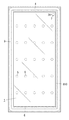
- FIG. 1 is a plan view of a glass panel unit according to an embodiment.
- 2 is a cross-sectional view taken along line AA in FIG.
- FIG. 3 is a plan view of a fitting including the glass panel unit same as above.
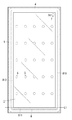
- FIG. 4 is a plan view of the glass panel unit of the first modification.
- FIG. 5 is a plan view of a joinery including the same glass panel unit.
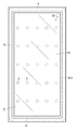
- FIG. 6 is a plan view of a glass panel unit of a second modification.
- FIG. 7 is a plan view of a fitting including the glass panel unit same as above.
- FIG. 8 is a plan view of a glass panel unit of a third modification.
- 9 is a cross-sectional view taken along line BB in FIG.
- FIG. 10 is a plan view of a fitting including the glass panel unit same as above.
- the glass panel unit of one embodiment includes a first glass panel 1, a second glass panel 2, a seal portion 4, a plurality of (many) spacers 5 and a getter 6.
- the first glass panel 1 and the second glass panel 2 are positioned to face each other.
- the first glass panel 1 and the second glass panel 2 are parallel to each other, and the seal portion 4, the plurality of spacers 5, and the getter 6 are located between the first glass panel 1 and the second glass panel 2.
- an internal space 81 surrounded by the frame-shaped seal portion 4 is formed between the first glass panel 1 and the second glass panel 2.
- the plurality of spacers 5 and the getter 6 are located in the internal space 81.
- first glass panel 1 and the second glass panel 2 various glass panels such as soda lime glass, high strain point glass, chemically tempered glass, alkali-free glass, quartz glass, neoceram, and physically tempered glass can be used.
- the seal portion 4 is formed by applying a glass frit to the opposing surface 22 of the second glass panel 2 in a frame shape using a dispenser or the like, and then attaching the glass frit to the first glass panel 1 and the second glass panel 2. It is formed by heating while sandwiched between the opposing surfaces 12 and 22. The peripheral edge portions of the first glass panel 1 and the second glass panel 2 are joined airtightly via the seal portion 4.
- the glass frit can be applied to the opposing surface 12 of the first glass panel 1, and can also be applied to the opposing surfaces 12 and 22 of the first glass panel 1 and the second glass panel 2. is there.
- the plurality of spacers 5 are distributed and spaced apart from each other. Each of the plurality of spacers 5 is located on both the opposing surface 12 of the first glass panel 1 and the opposing surface 22 of the second glass panel 2 (see FIG. 2). An infrared reflection film or the like may be coated on at least one of the facing surface 12 of the first glass panel 1 and the facing surface 22 of the second glass panel 2.
- the plurality of spacers 5 are positioned surrounded by the frame-shaped seal portion 4.
- the plurality of spacers 5 keep the distance between the first glass panel 1 and the second glass panel 2 at a predetermined distance.
- Each of the plurality of spacers 5 is preferably transparent or translucent.
- the material, dimensional shape, arrangement pattern, and the like of the plurality of spacers 5 can be set as appropriate.
- an exhaust hole 7 is formed on the second glass panel 2 side of the first glass panel 1 and the second glass panel 2 (see FIG. 2).
- the exhaust hole 7 is hermetically sealed with a sealing material 74.
- the structure for sealing the exhaust hole 7 is not limited to this, and the exhaust hole 7 may be sealed with another structure.
- the exhaust holes 7 may be formed in the first glass panel 1 or may be formed on both sides of the first glass panel 1 and the second glass panel 2.
- the getter 6 is a member configured to adsorb gas molecules, and is located at a distance from each of the plurality of spacers 5.
- the getter 6 is applied to the facing surface 22 of the second glass panel 2 using a dispenser or the like.
- the getter 6 may be disposed on the facing surface 12 of the first glass panel 1 or may be disposed on the facing surfaces 12 and 22 of both the first glass panel 1 and the second glass panel 2.
- the getter 6 is disposed in a frame-shaped region 810 along the rectangular frame-shaped seal portion 4 in the internal space 81.
- the frame-shaped region 810 is a region whose distance from the periphery of the glass panel unit is within a predetermined distance D.
- a frame-shaped region 810 and a region inside the frame-shaped region 810 are divided by a two-dot chain line.
- the getter 6 Since the getter 6 is positioned in the rectangular frame-shaped region 810, when the joinery frame 9 described later is mounted on the peripheral portion of the glass panel unit, the getter 6 is covered with the joinery frame 9 and the front side and It becomes difficult to visually recognize from the back side (see FIG. 3).
- the predetermined distance D is set to 10 cm in one embodiment, but the specific distance of the predetermined distance D is not limited to this.
- the predetermined distance D may be set to 8 cm, or set to 12 cm. It can be done.
- the getter 6 is positioned over the entire circumference of the frame-shaped region 810, and the plurality of spacers 5 and the exhaust holes 7 are positioned in a region inside the frame-shaped region 810.
- a slight gap of about 1 cm is interposed between the seal portion 4 and the getter 6 over the entire circumference, but the seal portion 4 and the getter 6 can also be in contact with the entire circumference. Part of the circumferential direction of the part 4 and the getter 6 can also contact each other.
- the sealed internal space 81 is a heat insulating space whose pressure is reduced to a degree of vacuum of 0.1 Pa or less, for example.
- the internal space 81 in a reduced pressure state is interposed between the first glass panel 1 and the second glass panel 2, thereby having high heat insulating properties.
- the frame-shaped getter 6 formed along the periphery of the internal space 81 is located in the decompressed internal space 81, the degree of vacuum of the internal space 81 is extended over a long period. Kept.
- joinery of one embodiment a joinery including the glass panel unit of one embodiment (hereinafter referred to as “joint of one embodiment”) will be described.
- FIG. 3 shows a joinery of one embodiment.
- This joinery has a structure in which a joinery frame 9 is fitted into the glass panel unit of one embodiment.
- joinery frame 9 is a window frame
- joinery shown in FIG. 3 is a window joinery provided with the glass panel unit of one embodiment.
- Other joinery such as a door may be used.
- the getter 6 is disposed over the entire circumference of the frame-like region 810 along the seal portion 4 in the internal space 81 of the glass panel unit.
- the entire frame-shaped region 810 is covered with the joinery frame 9 in a state where the joinery frame 9 having a width of about 10 cm is mounted on the peripheral edge of the glass panel unit. Therefore, both the seal part 4 and the getter 6 located inside thereof are covered with the joinery frame 9 and are hardly visible.
- the getter 6 is not arranged over the entire circumference of the frame-shaped region 810, but the first region 811 in the frame-shaped region 810. It is arranged only in.
- the first region 811 is a region that constitutes a portion of one side of the frame-shaped region 810 in a predetermined direction (vertical direction).
- a region excluding the first region 811 in the frame-shaped region 810 is a second region 812.
- the second region 812 constitutes a portion of the frame-like region 810 on the other side in a predetermined direction.
- the first area 811 and the second area 812 are divided with a virtual boundary line L1 as a boundary.
- region 811 is an area
- the first region 811 constitutes the lower half of the frame-shaped region 810.
- region 812 is an area
- the second region 812 constitutes the upper half of the frame-shaped region 810.
- the first region 811 is located below the second region 812.
- the getter 6 includes a straight line portion 61 along one side of the glass panel unit (lower end edge in a state where the joinery is constructed), a straight line portion 62 along the side adjacent to the one side of the glass panel unit (left end edge), and glass.
- a straight line portion 63 is included along another side (right edge) adjacent to the one side of the panel unit.
- linear portion 61 is referred to as a first linear portion 61
- linear portion 62 is referred to as a second linear portion 62
- linear portion 63 is referred to as a third linear portion 63. Called.
- the second straight portion 62 extends from one end of the first straight portion 61 in a direction (upward) orthogonal to the first straight portion 61.
- the third straight portion 63 extends from the other end of the first straight portion 61 in a direction (upward) orthogonal to the first straight portion 61.
- the getter 6 is generally U-shaped as a whole.
- the shape of the getter 6 is not limited to this, and for example, the straight portion 61 and the straight portion 62 may be discontinuous with each other, or the straight portion 61 and the straight portion 63 may be discontinuous with each other.
- the seal portion 4 and the getter 6 are disposed within a predetermined distance D from the periphery of the glass panel unit. It is difficult to see because it is covered with.
- the getter 6 is not arranged over the entire circumference of the frame-shaped region 810 but the first region 811 in the frame-shaped region 810 as in the first modified example. It is arranged only in.
- the boundary line L1 that divides the first region 811 and the second region 812 is positioned below the case of the first modified example in a state where the joinery is constructed.
- the boundary line L1 is located above the lower end edge of the glass panel unit of the second modification by a predetermined distance D in a state where the joinery is constructed.
- the getter 6 of the second modification has a linear shape along one side of the glass panel unit (lower end edge in the installed state).
- the getter 6 of the second modified example is configured by the first straight portion 61 of the first modified example.
- the seal portion 4 and the getter 6 are both covered with the joinery frame 9 and are not easily seen.
- the third glass panel 3 is further overlapped with the second glass panel 2, and a second internal space 82 is formed between the third glass panel 3 and the second glass panel 2. It is a structure (see FIGS. 8 and 9).
- the glass panel unit of the third modified example includes a hollow frame member 34 interposed between the peripheral edges of the third glass panel 3 and the second glass panel 2, and a desiccant filled in the hollow portion of the frame member 34. 36 and a second seal portion 38 formed in a frame shape so as to cover the outside of the frame member 34.
- the second internal space 82 is located surrounded by the frame member 34 and the second seal portion 38.
- the frame member 34 is formed of a metal such as aluminum and has a through hole 341 on the inner peripheral side.
- the hollow portion of the frame member 34 communicates with the second internal space 82 through the through hole 341.
- the desiccant 36 is, for example, silica gel.
- the second seal portion 38 is formed of a highly airtight resin such as silicon resin or butyl rubber.
- the 2nd internal space 82 enclosed by the frame member 34 and the 2nd seal part 38 is the space sealed from the outside.
- the second internal space 82 is filled with a dry gas (a dry rare gas such as argon, dry air, or the like).
- the glass panel unit of the third modified example was filled with a dry gas between the third glass panel 3 and the first glass panel 1 located on both sides in the thickness direction, and the internal space 81 decompressed until reaching a vacuum. By interposing the second internal space 82, it has high heat insulation.
- the seal portion 4 and the getter 6 are both covered with the joinery frame 9 and are not easily seen.
- the glass panel unit of the third modified example can include the substantially U-shaped getter 6 of the first modified example, and can also include the straight-line getter 6 of the second modified example. In this case, even if a part of the getter 6 is dropped after the construction, the dropped part is hidden by the joinery frame 9 and is hardly visible.
- the glass panel unit of the first form includes a first glass panel (1), a second glass panel (2), a frame-shaped seal portion (4), and the like. And a gas adsorption getter (6).
- the second glass panel (2) is positioned to face the first glass panel (1).
- the sealing part (4) is formed between the first glass panel (1) and the first glass panel (1) so as to form an internal space (81) sealed in a reduced pressure state between the first glass panel (1) and the second glass panel (2).
- the peripheral edge portions of the second glass panel (2) are joined in an airtight manner.
- the getter (6) is arranged in the internal space (81).
- the getter (6) includes a seal portion (4) in the internal space (81) so that the joinery frame (9) is covered with the joinery frame (9) when the glass panel unit of the first form is mounted.
- the frame-shaped region (810) is a region whose distance from the periphery of the glass panel unit of one embodiment is within a predetermined distance (D).
- the degree of vacuum of internal space (81) can be maintained over a long period of time by the getter (6) arranged in the frame-like region (810). Since the getter (6) is covered with the joinery frame 9 when the 9) is mounted, the getter (6) is hardly visible from the outside.
- the getter (6) is arranged over the entire circumference of the frame-like region (810).
- the degree of vacuum of the internal space (81) can be maintained over a long period of time by the getter (6) arranged over the entire circumference of the frame-like region (810). it can.
- the frame-shaped region (810) in the first mode, includes a first region (811) constituting a portion on one side in a predetermined direction in the frame-shaped region (810), The second region (812) constituting the other side of the predetermined direction in the frame region (810) is included, and the getter (6) is disposed in the first region (811).
- the glass panel unit of the third form is constructed so that the first region (811) is positioned below the second region (812), a part of the getter (6) is dropped due to external impact or the like. Even if it does, it becomes difficult to visually recognize the dropped part from the outside.
- the glass panel unit of the fourth form further includes a third glass panel (3) and a second internal space (502) in any one of the first to third forms.
- the third glass panel (3) is airtightly bonded to one of the first glass panel (1) and the second glass panel (2) through a frame-shaped second seal portion (38).
- the second internal space (502) is surrounded by the second seal portion (38) and filled with a dry gas.
- the heat-insulating internal space (81) and the second internal space (82) are provided, the heat-insulating property is further enhanced.
- the fitting of the first form is fitted into the glass panel unit of any one of the first to fourth forms and the peripheral portion of the glass panel unit.
- a fitting frame (9) is provided.
- the getter (6) is covered by the joinery frame (9).
- the degree of vacuum of the internal space (81) is maintained over a long period of time by the getter (6) that is covered with the joinery frame (9) and is hardly visible from the outside. be able to.
- the second form joinery includes a third form glass panel unit and a joinery frame (9) fitted in the peripheral portion of the glass panel unit.
- the predetermined direction is the vertical direction
- the first region (811) is located below the second region (812).
- the getter (6) located in the first region (811) is covered with the joinery frame (9).
- the degree of vacuum of the internal space (81) is maintained over a long period of time by the getter (6) that is covered with the joinery frame (9) and is hardly visible from the outside. be able to.
- the dropped part is difficult to be visually recognized from the outside.
- the third form of joinery is the second form of joinery, wherein the getter (6) is composed of at least a straight part (61).
- the straight line portion (61) is a straight getter located along the lower end edge of the glass panel unit of the third embodiment in the constructed state.
- the glass panel unit of the 3rd form is with respect to one of the 1st glass panel (1) and the 2nd glass panel (2).
- a third glass panel (3) that is hermetically bonded via a frame-shaped second seal portion (38), and a second internal space that is surrounded by the second seal portion (38) and that encloses dry gas ( 82).
- a glass panel unit and a fitting provided with this are not limited to above-mentioned embodiment, It is possible to perform an appropriate design change and to combine a well-known technique.
Landscapes
- Engineering & Computer Science (AREA)
- Chemical & Material Sciences (AREA)
- Civil Engineering (AREA)
- Structural Engineering (AREA)
- Life Sciences & Earth Sciences (AREA)
- General Chemical & Material Sciences (AREA)
- Geochemistry & Mineralogy (AREA)
- Materials Engineering (AREA)
- Organic Chemistry (AREA)
- Chemical Kinetics & Catalysis (AREA)
- Ceramic Engineering (AREA)
- Securing Of Glass Panes Or The Like (AREA)
- Joining Of Glass To Other Materials (AREA)
Abstract
Priority Applications (3)
| Application Number | Priority Date | Filing Date | Title |
|---|---|---|---|
| EP17774221.0A EP3438398B1 (fr) | 2016-03-31 | 2017-03-13 | Unité de panneau en verre et appareil la comprenant |
| US16/084,633 US10675844B2 (en) | 2016-03-31 | 2017-03-13 | Glass panel unit and building component including the same |
| JP2018508939A JPWO2017169677A1 (ja) | 2016-03-31 | 2017-03-13 | ガラスパネルユニット及びこれを備える建具 |
Applications Claiming Priority (2)
| Application Number | Priority Date | Filing Date | Title |
|---|---|---|---|
| JP2016072502 | 2016-03-31 | ||
| JP2016-072502 | 2016-03-31 |
Publications (1)
| Publication Number | Publication Date |
|---|---|
| WO2017169677A1 true WO2017169677A1 (fr) | 2017-10-05 |
Family
ID=59964208
Family Applications (1)
| Application Number | Title | Priority Date | Filing Date |
|---|---|---|---|
| PCT/JP2017/009869 Ceased WO2017169677A1 (fr) | 2016-03-31 | 2017-03-13 | Unité de panneau en verre et appareil la comprenant |
Country Status (5)
| Country | Link |
|---|---|
| US (1) | US10675844B2 (fr) |
| EP (1) | EP3438398B1 (fr) |
| JP (1) | JPWO2017169677A1 (fr) |
| TW (1) | TWI621598B (fr) |
| WO (1) | WO2017169677A1 (fr) |
Cited By (2)
| Publication number | Priority date | Publication date | Assignee | Title |
|---|---|---|---|---|
| EP3786128A4 (fr) * | 2018-04-27 | 2021-06-16 | Panasonic Intellectual Property Management Co., Ltd. | Unité de panneau en verre, fenêtre en verre, procédé de production d'unité de panneau en verre et procédé de production de fenêtre en verre |
| EP3786123A4 (fr) * | 2018-04-26 | 2021-06-16 | Panasonic Intellectual Property Management Co., Ltd. | Unité de panneau en verre, produit semi-fini d'unité de panneau en verre, produit assemblé d'unité de panneau en verre, et procédé de fabrication d'unité de panneau en verre |
Citations (2)
| Publication number | Priority date | Publication date | Assignee | Title |
|---|---|---|---|---|
| JP2000087656A (ja) * | 1998-09-14 | 2000-03-28 | Nippon Sheet Glass Co Ltd | ガラスパネル |
| WO2014136151A1 (fr) * | 2013-03-04 | 2014-09-12 | パナソニック株式会社 | Verre feuilleté, et procédé de fabrication de celui-ci |
Family Cites Families (21)
| Publication number | Priority date | Publication date | Assignee | Title |
|---|---|---|---|---|
| US2303897A (en) * | 1941-05-28 | 1942-12-01 | Pittsburgh Plate Glass Co | Multiple glazed unit |
| US4001994A (en) * | 1974-08-30 | 1977-01-11 | Schlegel Corporation | Glazing device |
| US4164085A (en) * | 1977-09-14 | 1979-08-14 | Hallmark Cards, Incorporated | Album having picture receiving frame assembly in cover |
| US4307551A (en) * | 1979-08-09 | 1981-12-29 | Ppg Industries, Inc. | System for cladding building exteriors |
| US4305773A (en) * | 1979-12-04 | 1981-12-15 | Hendricks Richard O | Art restoration table |
| US5079054A (en) * | 1989-07-03 | 1992-01-07 | Ominiglass Ltd. | Moisture impermeable spacer for a sealed window unit |
| CA2127265C (fr) * | 1992-01-31 | 2002-10-08 | Richard Edward Collins | Ameliorations relatives aux panneaux de vitrage isolants |
| US5489321A (en) * | 1994-07-14 | 1996-02-06 | Midwest Research Institute | Welding/sealing glass-enclosed space in a vacuum |
| JP3237544B2 (ja) * | 1996-10-11 | 2001-12-10 | 富士通株式会社 | 平面表示パネルの製造方法及び平面表示パネル |
| US6109994A (en) * | 1996-12-12 | 2000-08-29 | Candescent Technologies Corporation | Gap jumping to seal structure, typically using combination of vacuum and non-vacuum environments |
| KR20010020595A (ko) * | 1998-05-01 | 2001-03-15 | 이즈하라 요우조우 | 유리 패널과 유리 패널의 제조 방법 및 유리 패널에 사용하는 스페이서 |
| JPH11315668A (ja) * | 1998-05-07 | 1999-11-16 | Nippon Sheet Glass Co Ltd | ガラスパネル |
| DE60033156T2 (de) * | 1999-03-25 | 2007-10-31 | Nippon Sheet Glass Co., Ltd. | Glasscheibe und verfahren zu dessen herstellung |
| FR2793950A1 (fr) * | 1999-05-21 | 2000-11-24 | Thomson Plasma | Procede de fabrication de composants sur substrats de verre devant etre scelles, tels que des ecrans d'affichage plats du type panneau a plasma |
| US6478911B1 (en) * | 2000-09-27 | 2002-11-12 | Guardian Industries Corp. | Vacuum IG window unit with edge seal formed via microwave curing, and corresponding method of making the same |
| EP1509668B1 (fr) * | 2002-05-07 | 2006-11-08 | VKR Holding A/S | Element de panneau comprenant un cadre et une unite de panneau |
| JP2004149343A (ja) | 2002-10-29 | 2004-05-27 | Nippon Sheet Glass Co Ltd | ガラスパネル |
| DE102009040422A1 (de) * | 2009-09-07 | 2011-03-17 | Grenzebach Maschinenbau Gmbh | Verfahren und Vorrichtung zum Vakuum-dichten Aneinanderfügen von Glasplatten |
| US8950162B2 (en) | 2010-06-02 | 2015-02-10 | Eversealed Windows, Inc. | Multi-pane glass unit having seal with adhesive and hermetic coating layer |
| US10180606B2 (en) * | 2010-12-08 | 2019-01-15 | View, Inc. | Connectors for smart windows |
| ITMI20130774A1 (it) * | 2013-05-10 | 2014-11-10 | Getters Spa | Dispositivo di illuminazione trasparente composito |
-
2017
- 2017-03-13 US US16/084,633 patent/US10675844B2/en active Active
- 2017-03-13 JP JP2018508939A patent/JPWO2017169677A1/ja active Pending
- 2017-03-13 WO PCT/JP2017/009869 patent/WO2017169677A1/fr not_active Ceased
- 2017-03-13 EP EP17774221.0A patent/EP3438398B1/fr active Active
- 2017-03-14 TW TW106108240A patent/TWI621598B/zh not_active IP Right Cessation
Patent Citations (2)
| Publication number | Priority date | Publication date | Assignee | Title |
|---|---|---|---|---|
| JP2000087656A (ja) * | 1998-09-14 | 2000-03-28 | Nippon Sheet Glass Co Ltd | ガラスパネル |
| WO2014136151A1 (fr) * | 2013-03-04 | 2014-09-12 | パナソニック株式会社 | Verre feuilleté, et procédé de fabrication de celui-ci |
Non-Patent Citations (1)
| Title |
|---|
| See also references of EP3438398A4 * |
Cited By (3)
| Publication number | Priority date | Publication date | Assignee | Title |
|---|---|---|---|---|
| EP3786123A4 (fr) * | 2018-04-26 | 2021-06-16 | Panasonic Intellectual Property Management Co., Ltd. | Unité de panneau en verre, produit semi-fini d'unité de panneau en verre, produit assemblé d'unité de panneau en verre, et procédé de fabrication d'unité de panneau en verre |
| US12071371B2 (en) | 2018-04-26 | 2024-08-27 | Panasonic Intellectual Property Management Co., Ltd. | Glass panel unit, work in progress of glass panel unit, glass panel unit assembly, and method for manufacturing glass panel unit |
| EP3786128A4 (fr) * | 2018-04-27 | 2021-06-16 | Panasonic Intellectual Property Management Co., Ltd. | Unité de panneau en verre, fenêtre en verre, procédé de production d'unité de panneau en verre et procédé de production de fenêtre en verre |
Also Published As
| Publication number | Publication date |
|---|---|
| US10675844B2 (en) | 2020-06-09 |
| JPWO2017169677A1 (ja) | 2019-02-14 |
| EP3438398B1 (fr) | 2021-05-05 |
| EP3438398A1 (fr) | 2019-02-06 |
| US20190077122A1 (en) | 2019-03-14 |
| EP3438398A4 (fr) | 2019-03-27 |
| TWI621598B (zh) | 2018-04-21 |
| TW201736314A (zh) | 2017-10-16 |
Similar Documents
| Publication | Publication Date | Title |
|---|---|---|
| JP7165866B2 (ja) | ガラスパネルユニット及びガラスパネルユニットの製造方法 | |
| JP6994675B2 (ja) | ガラスパネルユニットの製造方法、およびガラス窓の製造方法 | |
| WO2011153381A3 (fr) | Unité de vitrage à pluralité de vitres comprenant un joint avec une couche de revêtement adhésive et hermétique | |
| US10787856B2 (en) | Glass panel unit and glass window | |
| WO2017169677A1 (fr) | Unité de panneau en verre et appareil la comprenant | |
| CN104341094B (zh) | 节能板材及其制造方法 | |
| JP2018012637A (ja) | 複層ガラスの製造方法 | |
| US20200039866A1 (en) | Glass panel unit manufacturing method, glass panel unit, and glass window with same | |
| JP6814986B2 (ja) | ガラスパネルユニット、ガラス窓、およびガラスパネルユニットの製造方法 | |
| JP6735509B2 (ja) | ガラスパネルユニットの製造方法、およびガラス窓の製造方法 | |
| JP6771183B2 (ja) | ガラスパネルユニットおよびこれを備えたガラス窓 | |
| JP6893321B2 (ja) | ガラスパネルユニット及びこれを備える建具の製造方法 | |
| JP7126130B2 (ja) | ガラスパネルユニット及びガラス窓 | |
| JP6709964B2 (ja) | ガラスパネルユニットの製造方法、およびガラス窓の製造方法 | |
| JPWO2018221208A1 (ja) | ガラスパネルユニットの製造方法及びガラス窓の製造方法 | |
| JP2005239448A (ja) | ガラスパネル接合構造とそれに使用するスペーサキー | |
| KR20100002747A (ko) | 페어 아크릴판의 제조방법 및 그 페어 아크릴판 |
Legal Events
| Date | Code | Title | Description |
|---|---|---|---|
| WWE | Wipo information: entry into national phase |
Ref document number: 2018508939 Country of ref document: JP |
|
| NENP | Non-entry into the national phase |
Ref country code: DE |
|
| WWE | Wipo information: entry into national phase |
Ref document number: 2017774221 Country of ref document: EP |
|
| ENP | Entry into the national phase |
Ref document number: 2017774221 Country of ref document: EP Effective date: 20181031 |
|
| 121 | Ep: the epo has been informed by wipo that ep was designated in this application |
Ref document number: 17774221 Country of ref document: EP Kind code of ref document: A1 |