WO2017169696A1 - Processus de production de couche réfléchissante, et couche réfléchissante - Google Patents
Processus de production de couche réfléchissante, et couche réfléchissante Download PDFInfo
- Publication number
- WO2017169696A1 WO2017169696A1 PCT/JP2017/010004 JP2017010004W WO2017169696A1 WO 2017169696 A1 WO2017169696 A1 WO 2017169696A1 JP 2017010004 W JP2017010004 W JP 2017010004W WO 2017169696 A1 WO2017169696 A1 WO 2017169696A1
- Authority
- WO
- WIPO (PCT)
- Prior art keywords
- liquid crystal
- reflective layer
- group
- composition
- cholesteric liquid
- Prior art date
- Legal status (The legal status is an assumption and is not a legal conclusion. Google has not performed a legal analysis and makes no representation as to the accuracy of the status listed.)
- Ceased
Links
Images



Classifications
-
- G—PHYSICS
- G02—OPTICS
- G02B—OPTICAL ELEMENTS, SYSTEMS OR APPARATUS
- G02B5/00—Optical elements other than lenses
- G02B5/08—Mirrors
-
- H—ELECTRICITY
- H05—ELECTRIC TECHNIQUES NOT OTHERWISE PROVIDED FOR
- H05B—ELECTRIC HEATING; ELECTRIC LIGHT SOURCES NOT OTHERWISE PROVIDED FOR; CIRCUIT ARRANGEMENTS FOR ELECTRIC LIGHT SOURCES, IN GENERAL
- H05B33/00—Electroluminescent light sources
- H05B33/02—Details
- H05B33/04—Sealing arrangements, e.g. against humidity
-
- C—CHEMISTRY; METALLURGY
- C01—INORGANIC CHEMISTRY
- C01B—NON-METALLIC ELEMENTS; COMPOUNDS THEREOF; METALLOIDS OR COMPOUNDS THEREOF NOT COVERED BY SUBCLASS C01C
- C01B32/00—Carbon; Compounds thereof
- C01B32/15—Nano-sized carbon materials
- C01B32/158—Carbon nanotubes
-
- C—CHEMISTRY; METALLURGY
- C09—DYES; PAINTS; POLISHES; NATURAL RESINS; ADHESIVES; COMPOSITIONS NOT OTHERWISE PROVIDED FOR; APPLICATIONS OF MATERIALS NOT OTHERWISE PROVIDED FOR
- C09K—MATERIALS FOR MISCELLANEOUS APPLICATIONS, NOT PROVIDED FOR ELSEWHERE
- C09K19/00—Liquid crystal materials
- C09K19/04—Liquid crystal materials characterised by the chemical structure of the liquid crystal components, e.g. by a specific unit
-
- C—CHEMISTRY; METALLURGY
- C09—DYES; PAINTS; POLISHES; NATURAL RESINS; ADHESIVES; COMPOSITIONS NOT OTHERWISE PROVIDED FOR; APPLICATIONS OF MATERIALS NOT OTHERWISE PROVIDED FOR
- C09K—MATERIALS FOR MISCELLANEOUS APPLICATIONS, NOT PROVIDED FOR ELSEWHERE
- C09K19/00—Liquid crystal materials
- C09K19/52—Liquid crystal materials characterised by components which are not liquid crystals, e.g. additives with special physical aspect: solvents, solid particles
- C09K19/58—Dopants or charge transfer agents
- C09K19/586—Optically active dopants; chiral dopants
-
- G—PHYSICS
- G02—OPTICS
- G02B—OPTICAL ELEMENTS, SYSTEMS OR APPARATUS
- G02B5/00—Optical elements other than lenses
- G02B5/08—Mirrors
- G02B5/0816—Multilayer mirrors, i.e. having two or more reflecting layers
- G02B5/0825—Multilayer mirrors, i.e. having two or more reflecting layers the reflecting layers comprising dielectric materials only
- G02B5/0841—Multilayer mirrors, i.e. having two or more reflecting layers the reflecting layers comprising dielectric materials only comprising organic materials, e.g. polymers
-
- G—PHYSICS
- G02—OPTICS
- G02B—OPTICAL ELEMENTS, SYSTEMS OR APPARATUS
- G02B5/00—Optical elements other than lenses
- G02B5/30—Polarising elements
-
- G—PHYSICS
- G02—OPTICS
- G02B—OPTICAL ELEMENTS, SYSTEMS OR APPARATUS
- G02B5/00—Optical elements other than lenses
- G02B5/30—Polarising elements
- G02B5/3016—Polarising elements involving passive liquid crystal elements
-
- G—PHYSICS
- G02—OPTICS
- G02F—OPTICAL DEVICES OR ARRANGEMENTS FOR THE CONTROL OF LIGHT BY MODIFICATION OF THE OPTICAL PROPERTIES OF THE MEDIA OF THE ELEMENTS INVOLVED THEREIN; NON-LINEAR OPTICS; FREQUENCY-CHANGING OF LIGHT; OPTICAL LOGIC ELEMENTS; OPTICAL ANALOGUE/DIGITAL CONVERTERS
- G02F1/00—Devices or arrangements for the control of the intensity, colour, phase, polarisation or direction of light arriving from an independent light source, e.g. switching, gating or modulating; Non-linear optics
- G02F1/01—Devices or arrangements for the control of the intensity, colour, phase, polarisation or direction of light arriving from an independent light source, e.g. switching, gating or modulating; Non-linear optics for the control of the intensity, phase, polarisation or colour
- G02F1/13—Devices or arrangements for the control of the intensity, colour, phase, polarisation or direction of light arriving from an independent light source, e.g. switching, gating or modulating; Non-linear optics for the control of the intensity, phase, polarisation or colour based on liquid crystals, e.g. single liquid crystal display cells
- G02F1/133—Constructional arrangements; Operation of liquid crystal cells; Circuit arrangements
- G02F1/1333—Constructional arrangements; Manufacturing methods
- G02F1/1335—Structural association of cells with optical devices, e.g. polarisers or reflectors
-
- G—PHYSICS
- G02—OPTICS
- G02F—OPTICAL DEVICES OR ARRANGEMENTS FOR THE CONTROL OF LIGHT BY MODIFICATION OF THE OPTICAL PROPERTIES OF THE MEDIA OF THE ELEMENTS INVOLVED THEREIN; NON-LINEAR OPTICS; FREQUENCY-CHANGING OF LIGHT; OPTICAL LOGIC ELEMENTS; OPTICAL ANALOGUE/DIGITAL CONVERTERS
- G02F1/00—Devices or arrangements for the control of the intensity, colour, phase, polarisation or direction of light arriving from an independent light source, e.g. switching, gating or modulating; Non-linear optics
- G02F1/01—Devices or arrangements for the control of the intensity, colour, phase, polarisation or direction of light arriving from an independent light source, e.g. switching, gating or modulating; Non-linear optics for the control of the intensity, phase, polarisation or colour
- G02F1/13—Devices or arrangements for the control of the intensity, colour, phase, polarisation or direction of light arriving from an independent light source, e.g. switching, gating or modulating; Non-linear optics for the control of the intensity, phase, polarisation or colour based on liquid crystals, e.g. single liquid crystal display cells
- G02F1/133—Constructional arrangements; Operation of liquid crystal cells; Circuit arrangements
- G02F1/1333—Constructional arrangements; Manufacturing methods
- G02F1/1337—Surface-induced orientation of the liquid crystal molecules, e.g. by alignment layers
-
- G—PHYSICS
- G02—OPTICS
- G02F—OPTICAL DEVICES OR ARRANGEMENTS FOR THE CONTROL OF LIGHT BY MODIFICATION OF THE OPTICAL PROPERTIES OF THE MEDIA OF THE ELEMENTS INVOLVED THEREIN; NON-LINEAR OPTICS; FREQUENCY-CHANGING OF LIGHT; OPTICAL LOGIC ELEMENTS; OPTICAL ANALOGUE/DIGITAL CONVERTERS
- G02F1/00—Devices or arrangements for the control of the intensity, colour, phase, polarisation or direction of light arriving from an independent light source, e.g. switching, gating or modulating; Non-linear optics
- G02F1/01—Devices or arrangements for the control of the intensity, colour, phase, polarisation or direction of light arriving from an independent light source, e.g. switching, gating or modulating; Non-linear optics for the control of the intensity, phase, polarisation or colour
- G02F1/13—Devices or arrangements for the control of the intensity, colour, phase, polarisation or direction of light arriving from an independent light source, e.g. switching, gating or modulating; Non-linear optics for the control of the intensity, phase, polarisation or colour based on liquid crystals, e.g. single liquid crystal display cells
- G02F1/137—Devices or arrangements for the control of the intensity, colour, phase, polarisation or direction of light arriving from an independent light source, e.g. switching, gating or modulating; Non-linear optics for the control of the intensity, phase, polarisation or colour based on liquid crystals, e.g. single liquid crystal display cells characterised by the electro-optical or magneto-optical effect, e.g. field-induced phase transition, orientation effect, guest-host interaction or dynamic scattering
- G02F1/139—Devices or arrangements for the control of the intensity, colour, phase, polarisation or direction of light arriving from an independent light source, e.g. switching, gating or modulating; Non-linear optics for the control of the intensity, phase, polarisation or colour based on liquid crystals, e.g. single liquid crystal display cells characterised by the electro-optical or magneto-optical effect, e.g. field-induced phase transition, orientation effect, guest-host interaction or dynamic scattering based on orientation effects in which the liquid crystal remains transparent
-
- H—ELECTRICITY
- H10—SEMICONDUCTOR DEVICES; ELECTRIC SOLID-STATE DEVICES NOT OTHERWISE PROVIDED FOR
- H10K—ORGANIC ELECTRIC SOLID-STATE DEVICES
- H10K50/00—Organic light-emitting devices
-
- C—CHEMISTRY; METALLURGY
- C09—DYES; PAINTS; POLISHES; NATURAL RESINS; ADHESIVES; COMPOSITIONS NOT OTHERWISE PROVIDED FOR; APPLICATIONS OF MATERIALS NOT OTHERWISE PROVIDED FOR
- C09K—MATERIALS FOR MISCELLANEOUS APPLICATIONS, NOT PROVIDED FOR ELSEWHERE
- C09K19/00—Liquid crystal materials
- C09K19/04—Liquid crystal materials characterised by the chemical structure of the liquid crystal components, e.g. by a specific unit
- C09K2019/0444—Liquid crystal materials characterised by the chemical structure of the liquid crystal components, e.g. by a specific unit characterized by a linking chain between rings or ring systems, a bridging chain between extensive mesogenic moieties or an end chain group
- C09K2019/0448—Liquid crystal materials characterised by the chemical structure of the liquid crystal components, e.g. by a specific unit characterized by a linking chain between rings or ring systems, a bridging chain between extensive mesogenic moieties or an end chain group the end chain group being a polymerizable end group, e.g. -Sp-P or acrylate
-
- G—PHYSICS
- G02—OPTICS
- G02F—OPTICAL DEVICES OR ARRANGEMENTS FOR THE CONTROL OF LIGHT BY MODIFICATION OF THE OPTICAL PROPERTIES OF THE MEDIA OF THE ELEMENTS INVOLVED THEREIN; NON-LINEAR OPTICS; FREQUENCY-CHANGING OF LIGHT; OPTICAL LOGIC ELEMENTS; OPTICAL ANALOGUE/DIGITAL CONVERTERS
- G02F2201/00—Constructional arrangements not provided for in groups G02F1/00 - G02F7/00
- G02F2201/34—Constructional arrangements not provided for in groups G02F1/00 - G02F7/00 reflector
- G02F2201/343—Constructional arrangements not provided for in groups G02F1/00 - G02F7/00 reflector cholesteric liquid crystal reflector
Definitions
- the present invention relates to a method for manufacturing a reflective layer and a reflective layer.
- a layer formed by fixing a cholesteric liquid crystal phase is known as a layer having a property of selectively reflecting either right circularly polarized light or left circularly polarized light in a specific wavelength range. Therefore, it is developed for various uses, and is used as, for example, a retardation layer (Patent Document 1).
- Patent Document 1 the direction of the alignment regulating force of the alignment film is in a random state, and the direction of the director of the liquid crystal compound in contact with the alignment film is random.
- an increase in viewing angle is required. More specifically, normally, when light is incident from the normal direction of the surface of the layer formed by fixing the cholesteric liquid crystal phase, either right circularly polarized light or left circularly polarized light is selectively reflected. . At this time, if reflection is performed not only in the normal direction but also in an oblique direction, the visibility from the oblique direction is improved. That is, the reflective layer is required to be excellent in characteristics (so-called diffuse reflection) that reflects incident light in various directions.
- the present inventors made a reflective layer using an alignment film not subjected to the rubbing treatment described in Patent Document 1, and studied the diffuse reflectivity. There was no need for further improvement.
- an object of the present invention is to provide a method for producing a reflective layer having excellent diffuse reflectivity and a reflective layer having excellent diffuse reflectivity.
- the present inventor has conducted earnest studies on the above-mentioned problems, and as a result, performs a treatment for increasing the helical induction power (HTP: Helical Twisting Power) of the chiral agent by a predetermined amount, thereby obtaining a reflective layer having desired characteristics. It was found that it can be manufactured. That is, it has been found that the above problem can be solved by the following configuration.
- HTP Helical Twisting Power
- Method. [2] The method for producing a reflective layer according to [1], wherein in step 2, the composition is cooled or heated so that the helical induction force of the chiral agent is increased by 10% or more.
- the composition is cooled or heated in step 2 so that the bright part and dark part derived from the cholesteric liquid crystal phase are changed to a state not parallel to the substrate.
- the liquid crystal compound is a liquid crystal compound having a polymerizable group, and in the step 2, the composition is cured to form a reflective layer formed by fixing the cholesteric liquid crystal phase.
- the fixation of the cholesteric liquid crystal phase in step 2 or the fixation of the cholesteric liquid crystal phase in step 3 is to fix the structure after cooling or heating the composition.
- a method for producing a reflective layer [7] The method for producing a reflective layer according to [5] or [6], wherein the fixation of the cholesteric liquid crystal phase in step 2 or the fixation of the cholesteric liquid crystal phase in step 3 is performed by a polymerization reaction by light irradiation.
- the reflective layer according to [16] wherein the surface irregularities are formed by a change in the orientation of the cholesteric liquid crystal phase.
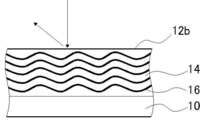
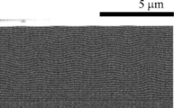
- FIG. 1 It is a schematic diagram at the time of observing the cross section of the layer of a general cholesteric liquid crystal phase state with a scanning electron microscope (SEM: Scanning * Electron * Microscope). It is a schematic diagram at the time of observing the cross section of the reflective layer manufactured with the manufacturing method of this invention by SEM. It is a schematic diagram when the cross section of the reflective layer of this invention is observed by SEM.
- 2 is a polarization microscope image of the reflective layer 1.
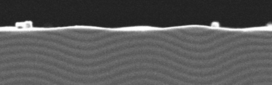
- 2 is a cross-sectional SEM observation view of a reflective layer 1.
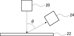
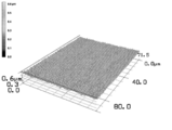
- FIG. It is the schematic of the apparatus used by diffuse reflectance evaluation. It is the surface analysis result of the shape measurement laser microscope of the reflective layer.
- 3 is a cross-sectional SEM observation view of a reflective layer 15.
- a numerical range represented by using “to” means a range including numerical values described before and after “to” as a lower limit value and an upper limit value.
- “(meth) acrylate” is a notation representing both acrylate and methacrylate
- “(meth) acryloyl group” is a notation representing both an acryloyl group and a methacryloyl group
- “(Meth) acryl” is a notation representing both acrylic and methacrylic.
- FIG. 1 shows a schematic cross-sectional view when a layer of a composition in a general cholesteric liquid crystal phase state is disposed on a substrate. As shown in FIG.
- the composition in the cholesteric liquid crystal phase state is subjected to a cooling treatment or a heat treatment so that the helical induction force of the chiral agent is increased by 5% or more.
- the twist of the liquid crystal compound becomes stronger, and the layer in the cholesteric liquid crystal phase changes so as to tilt.
- the bright portion 14 and the dark portion 16 have a wave-like structure (angulated structure) as shown in FIG. A layer 12b having a (a) structure.
- the spiral axis of the liquid crystal compound is inclined as shown in FIG. Part of the incident light is reflected in an oblique direction (see the arrow in FIG. 2). That is, a reflective layer excellent in diffuse reflectance can be obtained by the production method of the present invention.
- the manufacturing method of the reflective layer of this invention has the following process 1 and 2 at least.
- Step 1 A composition containing a liquid crystal compound and a chiral agent is applied onto a substrate, and the applied composition is heated to orient the liquid crystal compound to form a cholesteric liquid crystal phase.
- Step 2 A state of cholesteric liquid crystal phase The step of cooling or heating the composition to form a reflective layer so that the helical induction force of the chiral agent contained in the composition of 5 is increased by 5% or more. Materials used in each step and each step Will be described in detail.
- Step 1 is a step in which a composition containing a liquid crystal compound and a chiral agent is applied onto a substrate, and the applied composition is heated to align the liquid crystal compound to obtain a cholesteric liquid crystal phase.
- substrate is a board which supports the layer of the composition mentioned later.
- a transparent substrate is preferable.
- the transparent substrate intends a substrate having a visible light transmittance of 60% or more, and the transmittance is preferably 80% or more, and more preferably 90% or more.
- the material constituting the substrate is not particularly limited.
- the substrate may contain various additives such as UV (ultraviolet) absorbers, matting agent fine particles, plasticizers, deterioration inhibitors, and release agents.
- the substrate is preferably low birefringence in the visible light region.
- the retardation of the substrate at a wavelength of 550 nm is preferably 50 nm or less, and more preferably 20 nm or less.
- the thickness of the substrate is not particularly limited, but is preferably 10 to 200 ⁇ m, more preferably 20 to 100 ⁇ m, from the viewpoints of thinning and handling.
- the above thickness is intended to be an average thickness, and is obtained by measuring the thickness of any five points of the substrate and arithmetically averaging them.
- the thickness of the reflective layer (the cholesteric liquid crystal phase composition layer 12a) described later is also the same.
- liquid crystal compound The kind of liquid crystal compound is not particularly limited.
- liquid crystal compounds can be classified into a rod-shaped type (rod-shaped liquid crystal compound) and a disk-shaped type (discotic liquid crystal compound, disk-shaped liquid crystal compound) based on the shape.
- the rod-shaped type and the disk-shaped type include a low molecular type and a high molecular type, respectively.
- Polymer generally refers to a polymer having a degree of polymerization of 100 or more (Polymer Physics / Phase Transition Dynamics, Masao Doi, 2 pages, Iwanami Shoten, 1992).
- any liquid crystal compound can be used. Two or more liquid crystal compounds may be used in combination.
- the liquid crystal compound may have a polymerizable group.
- the kind of the polymerizable group is not particularly limited, and a functional group capable of addition polymerization reaction is preferable, and a polymerizable ethylenically unsaturated group or a ring polymerizable group is more preferable.
- the polymerizable group is preferably a (meth) acryloyl group, a vinyl group, a styryl group, an allyl group, an epoxy group, or an oxetane group, and more preferably a (meth) acryloyl group.
- a liquid crystal compound represented by the following formula (I) is preferable in that the diffuse reflectance of the reflective layer is more excellent.
- the number obtained by dividing the number of trans-1,4-cyclohexylene groups which may have a substituent represented by A by m is mc in that the diffuse reflectance of the reflective layer is more excellent.
- a liquid crystal compound satisfying mc> 0.1 is preferable, and a liquid crystal compound satisfying 0.4 ⁇ mc ⁇ 0.8 is more preferable.
- A represents a phenylene group which may have a substituent or a trans-1,4-cyclohexylene group which may have a substituent, and at least one of A has a substituent.
- a linking group selected from the group consisting of m represents an integer of 3 to 12
- Sp 1 and Sp 2 are each independently one or two in a single bond or a linear or branched alkylene group having 1 to 20 carbon atoms and a linear or branched alkylene group having 1 to 20 carbon atoms.
- Two or more —CH 2 — are —O—, —S—, —NH—, —N (CH 3 ) —, —C ( ⁇ O) —, —OC ( ⁇ O) —, or —C ( ⁇ O )
- A is a phenylene group which may have a substituent, or a trans-1,4-cyclohexylene group which may have a substituent.
- the phenylene group is preferably a 1,4-phenylene group.
- at least one of A is a trans-1,4-cyclohexylene group which may have a substituent.
- the m A's may be the same as or different from each other.
- M represents an integer of 3 to 12, preferably an integer of 3 to 9, more preferably an integer of 3 to 7, and still more preferably an integer of 3 to 5.
- the phenylene group and trans-1,4-cyclohexylene group may have 1 to 4 substituents. When it has two or more substituents, the two or more substituents may be the same or different from each other.
- the alkyl group may be linear or branched.
- the alkyl group preferably has 1 to 30 carbon atoms, more preferably 1 to 10 carbon atoms, and still more preferably 1 to 6 carbon atoms.
- Examples of the alkyl group include methyl group, ethyl group, n-propyl group, isopropyl group, n-butyl group, isobutyl group, sec-butyl group, tert-butyl group, n-pentyl group, isopentyl group, neopentyl group, Examples include 1,1-dimethylpropyl group, n-hexyl group, isohexyl group, heptyl group, octyl group, nonyl group, decyl group, undecyl group, and dodecyl group.
- alkyl group in the alkoxy group is the same as the description regarding the alkyl group.
- specific examples of the alkylene group referred to as an alkylene group include a divalent group obtained by removing one arbitrary hydrogen atom in each of the above examples of the alkyl group.
- the halogen atom include a fluorine atom, a chlorine atom, a bromine atom, and an iodine atom.
- the cycloalkyl group preferably has 3 or more carbon atoms, more preferably 5 or more, more preferably 20 or less, still more preferably 10 or less, still more preferably 8 or less, and particularly preferably 6 or less.
- the cycloalkyl group include a cyclopropyl group, a cyclobutyl group, a cyclopentyl group, a cyclohexyl group, a cycloheptyl group, and a cyclooctyl group.
- Examples of the substituent that the phenylene group and trans-1,4-cyclohexylene group may have include an alkyl group, an alkoxy group, and a group consisting of —C ( ⁇ O) —X 3 —Sp 3 —Q 3. Substituents selected from are preferred.
- X 3 represents a single bond, —O—, —S—, or —N (Sp 4 -Q 4 ) —, or represents a nitrogen atom that forms a ring structure with Q 3 and Sp 3. Show.
- Sp 3 and Sp 4 are each independently one or two in a single bond or a linear or branched alkylene group having 1 to 20 carbon atoms and a linear or branched alkylene group having 1 to 20 carbon atoms.
- Two or more —CH 2 — are —O—, —S—, —NH—, —N (CH 3 ) —, —C ( ⁇ O) —, —OC ( ⁇ O) —, or —C ( ⁇ O )
- Q 3 and Q 4 are each independently a hydrogen atom, a cycloalkyl group, or a cycloalkyl group, wherein one or more —CH 2 — is —O—, —S—, —NH—, —N (CH 3 ) —, —C ( ⁇ O) —, —OC ( ⁇ O) —, or a group substituted with —C ( ⁇ O) O—, or a group represented by formula (Q-1) to formula (Q-5) Any polymerizable group selected from the group consisting of:
- —CH 2 — is —O—, —S—, —NH—, —N (CH 3 ) —, —C ( ⁇ O) —, —OC ( ⁇ O).
- a linking group selected from the group consisting of CH ⁇ CH— is shown.
- L is preferably —C ( ⁇ O) O— or —OC ( ⁇ O) —.
- the m Ls may be the same as or different from each other.
- Sp 1 and Sp 2 are each independently one or two in a single bond or a linear or branched alkylene group having 1 to 20 carbon atoms and a linear or branched alkylene group having 1 to 20 carbon atoms.
- Sp 1 and Sp 2 are each independently the number of carbon atoms to which a linking group selected from the group consisting of —O—, —OC ( ⁇ O) —, and —C ( ⁇ O) O— is bonded to both ends. Selected from the group consisting of 1 to 10 linear alkylene groups, —OC ( ⁇ O) —, —C ( ⁇ O) O—, —O—, and linear alkylene groups having 1 to 10 carbon atoms.
- the linking group is preferably a combination of one or two or more groups, more preferably a linear alkylene group having 1 to 10 carbon atoms having —O— bonded to both ends.
- Q 1 and Q 2 each independently represent a hydrogen atom or a polymerizable group selected from the group consisting of groups represented by the following formulas (Q-1) to (Q-5). However, one of Q 1 and Q 2 represents a polymerizable group.
- an acryloyl group (formula (Q-1)) or a methacryloyl group (formula (Q-2)) is preferable.
- liquid crystal compound examples include a liquid crystal compound represented by the following formula (I-11), a liquid crystal compound represented by the formula (I-21), and a liquid crystal compound represented by the formula (I-31). Can be mentioned.
- a compound represented by formula (I) in JP2013-112231A, a compound represented by formula (I) in JP2010-70543A, a formula represented by JP2008-291218A A compound represented by formula (I), a compound represented by formula (I) in Japanese Patent No.
- Liquid crystal compound represented by formula (I-11) Liquid crystal compound represented by formula (I-11)
- R 11 represents a hydrogen atom, a linear or branched alkyl group having 1 to 12 carbon atoms, or —Z 12 —Sp 12 —Q 12
- L 11 represents a single bond, —C ( ⁇ O) O—, or —O (C ⁇ O) —
- L 12 represents —C ( ⁇ O) O—, —OC ( ⁇ O) —, or —CONR 2 —
- R 2 represents a hydrogen atom or an alkyl group having 1 to 3 carbon atoms
- Z 11 and Z 12 are each independently a single bond, —O—, —NH—, —N (CH 3 ) —, —S—, —C ( ⁇ O) O—, —OC ( ⁇ O) —, —OC ( ⁇ O) O— or —C ( ⁇ O) NR 12 —
- R 12 represents a hydrogen atom or —Sp 12 —Q 12
- Sp 11 and Sp 12 are each independently a single bond, a linear or
- the liquid crystal compound represented by the formula (I-11) has a polymerizable property in which R 12 is selected from the group consisting of groups represented by the formulas (Q-1) to (Q-5) as R 11 It contains at least one group —Z 12 —Sp 12 —Q 12 .
- Z 11 is —C ( ⁇ O) O— or —C ( ⁇ O) NR 12 —
- Q 11 is a compound represented by the formula (Q-1) to It is preferably —Z 11 —Sp 11 —Q 11 which is a polymerizable group selected from the group consisting of groups represented by formula (Q-5).
- Z 12 is —C ( ⁇ O) O— or —C ( ⁇ O) NR 12 —
- Q 12 is the formula (Q -1) to -Z 12 -Sp 12 -Q 12 which is a polymerizable group selected from the group consisting of groups represented by formula (Q-5).
- any 1,4-cyclohexylene group contained in the liquid crystal compound represented by the formula (I-11) is a trans-1,4-cyclohexylene group.
- L 11 is a single bond
- l 11 is 1 (dicyclohexyl group)
- Q 11 is Formula (Q-1) to Formula (Q-5).
- m 11 is 2
- l 11 is 0, and both R 11 are —Z 12 —Sp 12 —Q 12 .
- Q 12 is a polymerizable group selected from the group consisting of groups represented by formulas (Q-1) to (Q-5).
- Liquid crystal compound represented by formula (I-21) Liquid crystal compound represented by formula (I-21)
- Z 21 and Z 22 each independently represent a trans-1,4-cyclohexylene group which may have a substituent, or a phenylene group which may have a substituent
- Each of the above substituents is independently 1 to 4 substituents selected from the group consisting of —CO—X 21 —Sp 23 —Q 23 , an alkyl group, and an alkoxy group
- m21 represents an integer of 1 or 2
- n21 represents an integer of 0 or 1
- At least one of Z 21 and Z 22 is an optionally substituted phenylene group
- L 21 , L 22 , L 23 and L 24 are each independently a single bond, or —CH 2 O—, —OCH 2 —, — (CH 2 ) 2 OC ( ⁇ O) —, —C ( ⁇ O ) O (CH 2 ) 2 —, —C ( ⁇ O)
- —CH 2 — is —O—, —S—, —NH—, —N (CH 3 ) —, —C ( ⁇ O) —, —OC ( ⁇ O) —, Or a linking group selected from the group consisting of groups substituted with —C ( ⁇ O) O—
- Q 21 and Q 22 each independently represent any polymerizable group selected from the group consisting of groups represented by formulas (Q-1) to (Q-5)
- the liquid crystal compound represented by the formula (I-21) also preferably has a structure in which 1,4-phenylene groups and trans-1,4-cyclohexylene groups are present alternately, for example, m21 is 2.
- n21 is 0, and Z 21 is a trans-1,4-cyclohexylene group which may have a substituent from the Q 21 side, an arylene group which may have a substituent,
- m21 is 1, n21 is 1, Z 21 is an arylene group which may have a substituent, and Z 22 is an arylene group which may have a substituent. Is preferred.
- a liquid crystal compound represented by formula (I-31) is A liquid crystal compound represented by formula (I-31);
- R 31 and R 32 are each independently a group selected from the group consisting of an alkyl group, an alkoxy group, and —C ( ⁇ O) —X 31 —Sp 33 —Q 33 ; n31 and n32 each independently represents an integer of 0 to 4, X 31 represents a single bond, —O—, —S—, or —N (Sp 34 —Q 34 ) —, or represents a nitrogen atom that forms a ring structure with Q 33 and Sp 33 , Z 31 represents a phenylene group which may have a substituent, Z 32 represents a trans-1,4-cyclohexylene group which may have a substituent, or a phenylene group which may have a substituent, Each of the substituents is independently an alkyl group, an alkoxy group, and 1 to 4 substituents selected from the group consisting of —C ( ⁇ O) —X 31 —Sp 33 —Q 33 ; m31 represents an integer of 1
- a linking group selected from the group consisting of CH ⁇ CH—, Sp 31 , Sp 32 , Sp 33 and Sp 34 are each independently a single bond, or a linear or branched alkylene group having 1 to 20 carbon atoms, and a linear or branched alkylene group having 1 to 20 carbon atoms.
- Q 31 and Q 32 each independently represent any polymerizable group selected from the group consisting of groups represented by formulas (Q-1) to (Q-5), Q 33 and Q 34 are each independently a hydrogen atom, a cycloalkyl group, or a cycloalkyl group in which one or more —CH 2 — is —O—, —S—, —NH—, —N (CH 3 ) —, —C ( ⁇ O) —, —OC ( ⁇ O) —, or a group substituted with —C ( ⁇ O) O—, or Formula (Q-1) to Formula (Q-5) in the case represented indicates one polymerizable group selected from the group consist
- the compound represented by the formula (I) preferably has a partial structure represented by the following formula (II).
- formula (II) the black circles indicate the position of bonding with other parts of formula (I).
- the partial structure represented by the formula (II) may be included as a part of the partial structure represented by the following formula (III) in the formula (I).
- R 1 and R 2 are each independently selected from the group consisting of a hydrogen atom, an alkyl group, an alkoxy group, and a group represented by —C ( ⁇ O) —X 3 —Sp 3 —Q 3. It is a group.
- X 3 represents a single bond, —O—, —S—, or —N (Sp 4 -Q 4 ) —, or represents a nitrogen atom that forms a ring structure with Q 3 and Sp 3.
- X 3 is preferably a single bond or —O—.
- R 1 and R 2 are preferably —C ( ⁇ O) —X 3 —Sp 3 —Q 3 .
- R 1 and R 2 are preferably the same as each other.
- the bonding position of R 1 and R 2 to each phenylene group is not particularly limited.
- Sp 3 and Sp 4 are each independently one or two in a single bond or a linear or branched alkylene group having 1 to 20 carbon atoms and a linear or branched alkylene group having 1 to 20 carbon atoms.
- the above —CH 2 — is —O—, —S—, —NH—, —N (CH 3 ) —, —C ( ⁇ O) —, —OC ( ⁇ O) —, or —C ( ⁇ O).
- a linking group selected from the group consisting of groups substituted with O- is shown.
- Sp 3 and Sp 4 are each independently preferably a linear or branched alkylene group having 1 to 10 carbon atoms, more preferably a linear alkylene group having 1 to 5 carbon atoms, and a straight chain having 1 to 3 carbon atoms. Even more preferred are chain alkylene groups.
- Q 3 and Q 4 are each independently a hydrogen atom, a cycloalkyl group, or a cycloalkyl group, wherein one or more —CH 2 — is —O—, —S—, —NH—, —N (CH 3 ) —, —C ( ⁇ O) —, —OC ( ⁇ O) — or —C ( ⁇ O) O—, or a group represented by formula (Q-1) to formula (Q-5) Any polymerizable group selected from the group consisting of:
- the compound represented by the formula (I) preferably has, for example, a structure represented by the following formula (II-2).
- a 1 and A 2 each independently represent a phenylene group which may have a substituent or a trans-1,4-cyclohexylene group which may have a substituent.
- Each independently is an alkyl group, an alkoxy group, and 1 to 4 substituents selected from the group consisting of —C ( ⁇ O) —X 3 —Sp 3 —Q 3 ;
- a linking group selected from the group consisting of CH ⁇ CH—, n1 and n2 each independently represent
- liquid crystal compound represented by the formula (I) and satisfying 0.4 ⁇ mc ⁇ 0.8 examples include the following.
- Two or more liquid crystal compounds may be used in combination.
- two or more liquid crystal compounds represented by the formula (I) may be used in combination.
- a liquid crystal compound represented by the above formula (I) which is a liquid crystal compound represented by the formula (I) together with a liquid crystal compound satisfying 0.4 ⁇ mc ⁇ 0.8, It is preferable to use a liquid crystal compound satisfying ⁇ mc ⁇ 0.3.
- liquid crystal compound represented by the formula (I) and satisfying 0.1 ⁇ mc ⁇ 0.3 are as follows.
- liquid crystal compound used in the present invention a compound represented by the following formula (IV) described in JP-A-2014-198814, particularly, one (meth) acrylate group represented by formula (IV)
- a polymerizable liquid crystal compound having the following is also preferably used.
- a 1 represents an alkylene group having 2 to 18 carbon atoms, two or more CH 2 that is not one of the CH 2 or adjacent in the alkylene group is substituted by -O- May be;
- Z 1 represents —C ( ⁇ O) —, —O—C ( ⁇ O) — or a single bond;
- Z 2 represents —C ( ⁇ O) — or —C ( ⁇ O) —CH ⁇ CH—;
- R 1 represents a hydrogen atom or a methyl group;
- R 2 represents a hydrogen atom, a halogen atom, a linear alkyl group having 1 to 4 carbon atoms, a methoxy group, an ethoxy group, an optionally substituted phenyl group, a vinyl group, a formyl group, a nitro group, or a cyano group.
- P represents an acryl group, a methacryl group or a hydrogen atom
- Z 5 represents a single bond, —C ( ⁇ O) O—, —OC ( ⁇ O) —, —C ( ⁇ O) NR 1 —
- R 1 represents a hydrogen atom or a methyl group
- T is 1
- Sp represents a divalent aliphatic group having 1 to 12 carbon atoms which may have a substituent
- one CH 2 in the aliphatic group or two or more non-adjacent ones CH 2 may be substituted with —O—, —S—, —OC ( ⁇ O) —, —C ( ⁇ O) O— or —OC ( ⁇ O) O—.
- the compound represented by the formula (IV) is preferably a compound represented by the following formula (V).
- Formula (V) In the formula (V), n1 represents an integer of 3 to 6; R 11 represents a hydrogen atom or a methyl group; Z 12 represents —C ( ⁇ O) — or —C ( ⁇ O) —CH ⁇ CH—; R 12 represents a hydrogen atom, a linear alkyl group having 1 to 4 carbon atoms, a methoxy group, an ethoxy group, a phenyl group, an acryloylamino group, a methacryloylamino group, an allyloxy group, or the following formula (IV-3): Represents the structure to be -Z 51 -T-Sp-P Formula (IV-3) In formula (IV-3), P represents an acryl group or a methacryl group; Z 51 represents —C ( ⁇ O) O— or —OC ( ⁇ O) —; T represents 1,4-phenylene; Sp represents a di
- N1 represents an integer of 3 to 6, and is preferably 3 or 4.
- Z 12 represents —C ( ⁇ O) — or —C ( ⁇ O) —CH ⁇ CH—, and preferably represents —C ( ⁇ O) —.
- R 12 represents a hydrogen atom, a linear alkyl group having 1 to 4 carbon atoms, a methoxy group, an ethoxy group, a phenyl group, an acryloylamino group, a methacryloylamino group, an allyloxy group, or the above formula (IV-3).
- it represents a methyl group, an ethyl group, a methoxy group, an ethoxy group, a phenyl group, an acryloylamino group, a methacryloylamino group, or a structure represented by the above formula (IV-3).
- liquid crystal compound used in the present invention a compound represented by the following formula (VI) described in JP-A-2014-198814, particularly, a (meth) acrylate group represented by the following formula (VI):
- a liquid crystal compound that does not have the above is also preferably used.
- Z 3 represents —C ( ⁇ O) — or —CH ⁇ CH—C ( ⁇ O) —;
- Z 4 represents —C ( ⁇ O) — or —C ( ⁇ O) —CH ⁇ CH—;
- R 3 and R 4 are each independently a hydrogen atom, a halogen atom, a linear alkyl group having 1 to 4 carbon atoms, a methoxy group, an ethoxy group, an optionally substituted aromatic ring, a cyclohexyl group, Carbon number of vinyl group, formyl group, nitro group, cyano group, acetyl group, acetoxy group, acryloylamino group, N, N-dimethylamino group, maleimide group, methacryloylamino group, allyloxy group, allyloxycarbamoyl group, alkyl group Is an N-alkyloxycarbamoyl group, N- (2-methacryloyloxye
- P represents an acryl group, a methacryl group or a hydrogen atom
- Z 5 represents —C ( ⁇ O) O—, —OC ( ⁇ O) —, —C ( ⁇ O) NR 1 —.
- R 1 represents a hydrogen atom or a methyl group
- T represents 1,4-phenylene.
- Sp represents a divalent aliphatic group having 1 to 12 carbon atoms which may have a substituent.
- the compound represented by the above formula (VI) is preferably a compound represented by the following formula (VII).
- Z 13 represents —C ( ⁇ O) — or —C ( ⁇ O) —CH ⁇ CH—;
- Z 14 represents —C ( ⁇ O) — or —CH ⁇ CH—C ( ⁇ O) —;
- R 13 and R 14 are each independently a hydrogen atom, a linear alkyl group having 1 to 4 carbon atoms, a methoxy group, an ethoxy group, a phenyl group, an acryloylamino group, a methacryloylamino group, an allyloxy group, or the above formula ( It represents the structure represented by IV-3).
- Z 13 represents —C ( ⁇ O) — or —C ( ⁇ O) —CH ⁇ CH—, preferably —C ( ⁇ O) —.
- R 13 and R 14 are each independently a hydrogen atom, a linear alkyl group having 1 to 4 carbon atoms, a methoxy group, an ethoxy group, a phenyl group, an acryloylamino group, a methacryloylamino group, an allyloxy group, or the above formula
- a structure represented by the above formula (IV-3) a methyl group, an ethyl group, a methoxy group, an ethoxy
- liquid crystal compound used in the present invention a compound represented by the following formula (VIII) described in JP-A-2014-198814, particularly, two (meta) compounds represented by the following formula (VIII) are used.
- a polymerizable liquid crystal compound having an acrylate group is also preferably used.
- a 2 and A 3 each independently represent an alkylene group having 2 to 18 carbon atoms, two or more CH 2 not one CH 2 or adjacent in the alkylene group, Optionally substituted with -O-;
- Z 5 represents —C ( ⁇ O) —, —OC ( ⁇ O) — or a single bond;
- Z 6 represents —C ( ⁇ O) —, —C ( ⁇ O) O— or a single bond;
- R 5 and R 6 each independently represents a hydrogen atom or a methyl group;
- L 9 , L 10 , L 11 and L 12 are each independently an alkyl group having 1 to 4 carbon atoms, an alkoxy group having 1 to 4 carbon atoms, an alkoxycarbonyl group having 2 to 5 carbon atoms, or 2 to 4 represents an acyl group, a halogen atom or a hydrogen atom, and at least one of L 9 , L 10 , L 11 and L 12 represents a group other than a hydrogen atom.
- the compound represented by the formula (VIII) is preferably a compound represented by the following formula (IX).
- n2 and n3 each independently represents an integer of 3 to 6; R 15 and R 16 each independently represents a hydrogen atom or a methyl group.
- n2 and n3 each independently represent an integer of 3 to 6, and n2 and n3 are preferably 4.
- R 15 and R 16 each independently represent a hydrogen atom or a methyl group, and it is preferable that R 15 and R 16 represent a hydrogen atom.
- Such a liquid crystal compound can be produced by a known method.
- the composition includes a chiral agent.
- the kind of chiral agent is not particularly limited.
- the chiral agent may be liquid crystalline or non-liquid crystalline.
- the chiral agent includes various known chiral agents (for example, liquid crystal device handbook, chapter 3-4-3, chiral agent for TN (Twisted Nematic), STN (Super Twisted Nematic), page 199, Japan Society for the Promotion of Science, 142nd. From the committee edition, described in 1989).
- Chiral agents generally contain asymmetric carbon atoms.
- an axially asymmetric compound or a planar asymmetric compound that does not contain an asymmetric carbon atom can also be used as a chiral agent.
- Examples of the axial asymmetric compound or the planar asymmetric compound include binaphthyl, helicene, paracyclophane, and derivatives thereof.
- the chiral agent may have a polymerizable group.
- the content of the chiral agent is preferably 0.5 to 30% by mass with respect to the total mass of the liquid crystal compound.
- a smaller amount of chiral agent is preferred because it tends not to affect liquid crystallinity. Therefore, as the chiral agent, a compound having a strong twisting power is preferable so that a twisted orientation with a desired helical pitch can be achieved even with a small amount.
- the chiral agent exhibiting such a strong twisting force include, for example, JP 2002-302487, JP 2002-80478, JP 2002-80851, JP 2002-179668, and JP 2002.
- composition may contain components other than the liquid crystal compound and the chiral agent.
- the composition may contain a polymerization initiator.
- the composition when the liquid crystal compound has a polymerizable group, the composition preferably contains a polymerization initiator.
- the polymerization initiator is preferably a photopolymerization initiator capable of initiating a polymerization reaction by ultraviolet irradiation. Examples of the photopolymerization initiator include ⁇ -carbonyl compounds (described in US Pat. Nos. 2,367,661 and 2,367,670), acyloin ether (described in US Pat. No. 2,448,828), ⁇ -hydrocarbon substituted aromatic acyloin. Compound (described in US Pat. No.
- the content of the polymerization initiator in the composition is not particularly limited, but is preferably 0.1 to 20% by mass and more preferably 1 to 8% by mass with respect to the total mass of the liquid crystal compound.
- the composition may contain an alignment control agent.
- an alignment control agent in the composition, it becomes possible to form a stable or rapid cholesteric liquid crystal phase.
- a layer 30 (a layer of a composition in a cholesteric liquid crystal phase state) can be produced.
- orientation control agent examples include fluorine-containing (meth) acrylate polymers, compounds represented by general formulas (X1) to (X3) described in WO2011 / 162291, and paragraphs [0007] of JP2012-211306.
- fluorine-containing (meth) acrylate polymers compounds represented by general formulas (X1) to (X3) described in WO2011 / 162291, and paragraphs [0007] of JP2012-211306.
- compounds described in paragraphs [0020] to [0031] of JP2013-47204 compounds described in paragraphs [0165] to [0170] of WO2016 / 009648, WO2016 / 092844, paragraphs [0077] to [0081]
- general formulas (Cy201) to (Cy211) described in Japanese Patent No. 4592225 You may contain 2 or more types selected from these.
- orientation control agent may be used individually by 1 type, and may use 2 or more types together.
- the content of the alignment control agent in the composition is not particularly limited, but is preferably 0.01 to 10% by mass, more preferably 0.01 to 5% by mass, and more preferably 0.01 to 5% by mass with respect to the total mass of the liquid crystal compound. 1% by mass is more preferable.
- the composition may contain a solvent.
- the solvent include water or an organic solvent.
- the organic solvent include amides such as N, N-dimethylformamide; sulfoxides such as dimethyl sulfoxide; heterocyclic compounds such as pyridine; hydrocarbons such as benzene and hexane; alkyl halides such as chloroform and dichloromethane; Esters such as methyl, butyl acetate and propylene glycol monoethyl ether acetate; Ketones such as acetone, methyl ethyl ketone, cyclohexanone and cyclopentanone; Ethers such as tetrahydrofuran and 1,2-dimethoxyethane; 1,4-butanediol di Acetate; and the like. These may be used alone or in combination of two or more.
- the composition includes one or more antioxidants, ultraviolet absorbers, sensitizers, stabilizers, plasticizers, chain transfer agents, polymerization inhibitors, antifoaming agents, leveling agents, thickeners, Other additives such as flame retardants, surfactants, dispersants, and colorants such as dyes and pigments may be included.
- the composition it is preferable that at least one of the compounds constituting the composition is a compound having a plurality of polymerizable groups (polyfunctional compound). Furthermore, in the composition, the total content of the compound having a plurality of polymerizable groups is preferably 80% by mass or more based on the total solid content in the composition.
- the solid content is a component that forms a reflective layer and does not include a solvent.
- the corrugated structure of the reflective layer 30 (cholesteric liquid crystal phase) or the irregular structure on the surface can be firmly fixed to impart durability.
- the compound having a plurality of polymerizable groups is a compound having two or more immobilizable groups in one molecule.
- the polyfunctional compound contained in the composition may be liquid crystalline or non-liquid crystalline.
- step 1 First, the above-described composition is applied onto a substrate.
- the application method is not particularly limited, and examples thereof include a wire bar coating method, an extrusion coating method, a direct gravure coating method, a reverse gravure coating method, and a die coating method.
- the substrate Prior to application of the composition, the substrate may be subjected to a known rubbing treatment.
- the film thickness of the composition (composition layer) applied on the substrate is not particularly limited, but is preferably 0.1 to 20 ⁇ m, more preferably 0.2 to 15 ⁇ m, from the viewpoint that the diffuse reflection property of the reflective layer is more excellent. 0.5 to 10 ⁇ m is more preferable.
- the liquid crystal phase transition temperature of the composition is preferably in the range of 10 to 250 ° C., more preferably in the range of 10 to 150 ° C., from the viewpoint of production suitability.
- the liquid crystal compound is not heated to a temperature at which the liquid crystal compound becomes isotropic (Iso). If the composition is heated above the temperature at which the liquid crystal compound becomes isotropic, defects in the cholesteric liquid crystal phase increase, which is not preferable.
- Step 2 is a step of cooling or heating the composition to form a reflective layer so that the helical induction force of the chiral agent contained in the composition in the cholesteric liquid crystal phase obtained in Step 1 is increased by 5% or more. It is. That is, in the process of cooling or heating the coating layer so that the helical induction force of the chiral agent contained in the composition constituting the coating layer (composition layer) formed on the substrate is increased by 5% or more. is there. As described above, by performing this step, the twist of the liquid crystal compound is further increased. As a result, the orientation of the cholesteric liquid crystal phase (inclination of the helical axis) is changed, and thereby, the bright portion parallel to the substrate 10 is changed.
- the reflective layer 30 having periodic irregularities on the surface as shown in FIG. 3 can be formed by the change in the orientation of the cholesteric liquid crystal phase.
- HTP helical induction force
- the concentration of the chiral agent is intended to mean the concentration (% by mass) of the chiral agent with respect to the total solid content in the composition.
- the HTP value is affected not only by the type of chiral agent but also by the type of liquid crystal compound contained in the composition.
- a composition containing a predetermined chiral agent X and a liquid crystal compound A and a composition containing a liquid crystal compound B different from the predetermined chiral agent X and liquid crystal compound A are prepared, and both HTPs are prepared at the same temperature. If measured, the value may be different.
- the value of HTP varies depending on the length of the helical pitch formed in the composition, and the length of the helical pitch can be appropriately adjusted depending on the temperature of the composition. That is, the length of the helical pitch can be adjusted by subjecting the composition to cooling treatment or heat treatment.
- the increase rate Z represented by the following formula (2) is intended to be 5% or more.
- Rate of increase Z (%) ⁇ (Y ⁇ X) / X ⁇ ⁇ 100
- the increase rate Z should just be 5% or more, and 10% or more is more preferable.
- the increase rate Z is more preferably 12% or more in that the diffuse reflectance of the reflective layer is more excellent.
- the upper limit of the rate of increase Z is not particularly limited, but is often 30% or less.
- the composition is cooled or heated so that the helical induction force of the chiral agent is increased by 5% or more.
- it is preferable to cool the composition it is preferable to cool the composition so that the temperature of the composition is lowered by 30 ° C. or more in that the diffuse reflectance of the reflective layer is more excellent.
- the upper limit value of the reduced temperature range of the cooling treatment is not particularly limited, but is usually about 70 ° C.
- the cooling treatment is intended to cool the composition so that it is T-30 ° C. or lower when the temperature of the composition in the cholesteric liquid crystal phase before cooling is T ° C.
- the cooling method is not particularly limited, and examples thereof include a method in which the substrate on which the composition is disposed is left in an atmosphere at a predetermined temperature.
- the cooling rate in the cooling process is preferably at a certain speed.
- the maximum cooling rate in the cooling process is preferably 1 ° C. or more per second, more preferably 2 ° C. or more per second, and further preferably 3 ° C. or more per second.
- the upper limit of the cooling rate is not particularly limited, but is often 10 ° C. or less per second.
- the chiral agent after the helical induction force has increased by 5% or more preferably has a helical induction force of 20 or more, and more preferably 30 or more.
- the upper limit is not particularly limited, but is often 100 or less.
- the wind speed of the environment to which the composition layer (liquid crystal layer) is exposed is low in all steps from application to heating to cooling.
- the wind speed of the environment to which the composition layer is exposed is preferably 1 m / s or less in all steps of coating, heating and cooling the composition.
- the composition on the substrate may be cured to fix the cholesteric liquid crystal phase. That is, you may implement a hardening process simultaneously with the said cooling process or heat processing.
- the resulting reflective layer corresponds to a layer formed by fixing a cholesteric liquid crystal phase.
- the state in which the cholesteric liquid crystal phase is “fixed” is the most typical and preferred mode in which the orientation of the liquid crystal compound in the cholesteric liquid crystal phase is maintained.
- the layer is not fluid in a temperature range of usually 0 to 50 ° C., and in a temperature range of ⁇ 30 to 70 ° C. under harsher conditions, and it is in an oriented form by an external field or an external force.
- the fixation of the cholesteric liquid crystal phase is preferably to fix the structure (alignment state) of the cholesteric liquid crystal phase after the cooling treatment or the heat treatment.
- the method for the curing treatment is not particularly limited, and examples thereof include photocuring treatment and thermosetting treatment. Of these, light irradiation treatment is preferable, and ultraviolet irradiation treatment is more preferable.
- the liquid crystal compound is preferably a liquid crystal compound having a polymerizable group.
- the curing treatment is preferably a polymerization reaction by light irradiation (particularly ultraviolet irradiation), and more preferably a radical polymerization reaction by light irradiation (particularly ultraviolet irradiation).
- a light source such as an ultraviolet lamp is used.
- the amount of ultraviolet irradiation energy is not particularly limited, but generally it is preferably about 0.1 to 0.8 J / cm 2 .
- the time for irradiation with ultraviolet rays is not particularly limited, but may be appropriately determined from the viewpoints of sufficient strength and productivity of the resulting layer.
- a reflective layer having a wave-like structure in a bright part and a dark part in a cross-sectional SEM observation view as shown in FIG. 2 is formed.
- the reflection layer is a layer having a cholesteric liquid crystal structure and a structure in which an angle formed by the spiral axis and the surface of the reflection layer is periodically changed.
- the reflective layer has a cholesteric liquid crystal structure, and the cholesteric liquid crystal structure gives a stripe pattern of a bright part and a dark part in a cross-sectional view of the reflective layer observed with a scanning electron microscope, and at least one dark part is formed.
- JP-A-2006-284862 after applying a composition containing a liquid crystal compound, it is heated to a temperature at which the liquid crystal compound becomes an isotropic phase, and then a gas is blown from a predetermined direction to produce a liquid crystal compound. Describes a method of manufacturing an anisotropic optical element in which the spiral axis direction of a cholesteric liquid crystal phase is inclined by lowering the temperature to a temperature at which becomes a cholesteric liquid crystal phase.
- the anisotropic optical element formed by this method exhibits anisotropy in the reflection of light, but can reflect light only in the direction corresponding to the inclination direction of the helical axis, and is similar to the reflection layer according to the present invention. Good diffuse reflectivity is not exhibited.
- a plurality of reflective layers may be formed on the substrate.
- the reflective layer Y having a selective reflection wavelength different from the reflective layer X may be formed by the same procedure.
- the production method of the present invention by performing at least one of selection of a chiral agent and / or an orientation control agent and selection of conditions for heat treatment or cooling treatment, as conceptually shown in FIG.
- a reflective layer having a flat (substantially flat) surface surface opposite to the substrate 10
- a wavy structure (unevenness) of the bright portion 14 and the dark portion 16 in the cross section as conceptually shown in FIG.
- the reflective layer 30 of the present invention having periodic irregularities on the surface can be produced.
- the surface of the reflective layer 30 can be made uneven by increasing the wave-like structure in the reflective layer 30 by selecting a chiral agent that has a large inductive force of the corrugated structure in the reflective layer 30.
- the surface of the reflective layer 30 can be similarly made uneven. Further, by increasing the difference between the heating temperature in step 1 and the cooling temperature in step 2, the surface of the reflective layer 30 can be similarly made uneven. Furthermore, by increasing the cooling rate in step 2, the surface of the reflective layer 30 can be similarly made uneven.
- the reflective layer 30 of the present invention is a reflective layer formed by fixing a cholesteric liquid crystal phase, and similarly to the reflective layer shown in FIG. 2, the bright portion 14 of the cross section of the cholesteric liquid crystal phase formed by the helical structure of the cholesteric liquid crystal phase.
- the dark portion 16 has a wavy structure, and further has periodic irregularities on the surface.
- corrugation (convex part) is formed two-dimensionally (refer FIG. 7). Therefore, the wave-like structures of the bright portion 14 and the dark portion 16 in the cross section of the reflective layer 30 (cholesteric liquid crystal phase) are not limited to the horizontal direction shown in FIG. A wavy structure is formed. That is, the reflection layer 30 has a wavy structure of the bright part 14 and the dark part 16 in the cross sections in all directions. In this regard, the same applies to the reflective layer shown in FIG. However, the present invention is not limited to this, and the reflective layer may have a wave-like structure in which continuous waves are formed only in one direction in a cross section or further on the surface.
- the reflection layer 30 has a wave-like structure of the bright portion 14 and the dark portion 16 in cross sections in all directions, as described above, or, in addition, as shown in FIG. A structure in which the unevenness is formed two-dimensionally is preferable.
- the irregularities on the surface of the reflective layer 30 are periodic, but the phase is different from the wave-like structure of the cross section. Specifically, the unevenness on the surface of the reflective layer 30 has a phase shifted by half (substantially half) with respect to the corrugated structure of the cross section. Accordingly, in the surface direction of the substrate 10, the position of the convex portion of the corrugated structure in the cross section of the reflective layer 30 becomes the position of the concave portion of the concave and convex portions on the surface of the reflective layer 30, and the position of the concave portion of the corrugated structure in the cross section of the reflective layer 30 is reflected. It becomes the position of the convex and concave portions on the surface of the layer 30.
- the reflective layer 30 basically has a pitch p ⁇ b> 1 of the surface irregularities equal to a pitch p ⁇ b> 2 of the corrugated structure in the cross section. That is, in the reflective layer 30 of the present invention, the period of the irregularities on the surface is equal to the period of the corrugated structure in the cross section.
- the pitch p ⁇ b> 1 is the interval between the vertices of the convex portions on the surface of the reflective layer 30, and the pitch p ⁇ b> 2 is the interval between the vertices of the waves in the dark portion 16 closest to the surface of the reflective layer 30.
- the fact that the pitch p1 and the pitch p2 are equal is calculated not only when the pitch p1 and the pitch p2 completely match, but also by “[(p1-p2) / p1] ⁇ 100”. This includes the case where the pitch difference is ⁇ 30% or less.
- the wave-like structure of the bright part 14 and the dark part 16 in the cross section of the reflective layer 30 has a uniform wave pitch (period), but the wave height is The center (central region) in the thickness direction of the reflective layer 30 is the highest, and gradually decreases toward the surface side in the thickness direction and the substrate 10 side. That is, the amplitude of the corrugated structure in the cross section of the reflective layer 30 is largest at the center in the thickness direction and gradually decreases toward the surface side and the substrate 10 side.
- the reflective layer (the layer 12b having the wavy structure) having no irregularities on the surface shown in FIG.
- the wave-like structure of the reflective layer 30 having irregularities on the surface shown in FIG. 3 is a structure having waves of uniform height throughout the thickness direction, like the wave-like structure of the reflective layer shown in FIG. Also good.
- the reflection layer 30 having irregularities on the surface thereof has a wave height (wave amplitude of the wave-like structure of the bright portion 14 and the dark portion 16 due to the spiral structure of the cholesteric liquid crystal phase in the cross section of the reflection layer 30 (cholesteric liquid crystal phase). ) Is larger than the flat reflective layer shown in FIG. That is, if the reflective layer 30 has a large wave-like structure, the unevenness is also transmitted to the surface, and the surface shape of the reflective layer 30 becomes uneven. Therefore, as shown in FIG. 3, the reflective layer 30 having irregularities on the surface can obtain higher diffuse reflectivity.
- the pitch p2 of the corrugated structure in the cross section In order to obtain good high diffuse reflectivity in the reflective layer 30, it is preferable to narrow the pitch p2 of the corrugated structure in the cross section and increase (high) the wave of the corrugated structure in the cross section.
- the uneven state of the surface of the reflective layer 30 is greatly influenced by the corrugated structure of the cross section. Therefore, in order to obtain good diffuse reflectivity in the reflective layer 30, it is preferable to reduce the pitch p1 of the unevenness on the surface and increase (deeply) the height h of the unevenness. In particular, the higher the unevenness height h, the higher the diffuse reflectance.
- the unevenness pitch p1 on the surface of the reflective layer 30 is narrowed, the unevenness height h tends to decrease, and when the unevenness height h is increased, the unevenness pitch p1 tends to decrease.
- the unevenness pitch p1 of the reflective layer 30 is preferably 0.5 to 10 ⁇ m, and more preferably 1 to 6 ⁇ m.
- the unevenness height h of the reflective layer 30 is preferably 1 to 500 nm, more preferably 5 to 300 nm, still more preferably 50 to 300 nm, and particularly preferably 65 to 200 nm.
- the thickness of the reflective layer 30 is not particularly limited, and the thickness satisfying the diffuse reflectance required for the reflective layer 30 is determined depending on the size of the reflective layer 30 in the surface direction, the material for forming the reflective layer 30, and the like. It can be set as appropriate.
- the thickness of the reflective layer 30 is preferably 0.3 to 20 ⁇ m, and more preferably 0.5 to 10 ⁇ m. By setting the thickness of the reflective layer 30 to 0.3 ⁇ m or more, good diffuse reflectance can be obtained by the reflective layer 30 having a sufficient thickness. Further, by setting the thickness of the reflective layer 30 to 20 ⁇ m or less, it is possible to prevent the reflective layer 30 from becoming unnecessarily thick, and for example, it is possible to make a projection image display member, which will be described later, thin. As described above, when a plurality of reflective layers are provided on the substrate 10, the thickness per layer is preferably within this range. Moreover, it is preferable that the thickness of the reflection layer which does not have an unevenness
- the reflective layer is a layer having a cholesteric liquid crystal phase (cholesteric liquid crystal structure) having a predetermined wavy structure (hereinafter, the reflective layer is also referred to as “cholesteric liquid crystal layer”), and is a layer formed by fixing this cholesteric liquid crystal phase. It is preferable that The cholesteric liquid crystal layer is a layer that exhibits selective reflection characteristics with respect to light in a predetermined wavelength range.
- the cholesteric liquid crystal layer functions as a circularly polarized light selective reflection layer that selectively reflects either the right circularly polarized light or the left circularly polarized light and transmits the other circularly polarized light in the selective reflection wavelength region.
- a film containing one or more cholesteric liquid crystal layers can be used for various applications.
- the sense of circularly polarized light reflected by each cholesteric liquid crystal layer may be the same or opposite depending on the application.
- the center wavelength of selective reflection described later of each cholesteric liquid crystal layer may be the same or different depending on the application.
- the term “sense” for circularly polarized light means whether it is right circularly polarized light or left circularly polarized light.
- the sense of circularly polarized light is right-handed circularly polarized light when the electric field vector tip turns clockwise as time increases when viewed as the light travels toward you, and left when it turns counterclockwise. Defined as being circularly polarized.
- the term “sense” may be used for the twist direction of the spiral of the cholesteric liquid crystal.
- the selective reflection by the cholesteric liquid crystal reflects right circularly polarized light when the twist direction (sense) of the cholesteric liquid crystal spiral is right, transmits left circularly polarized light, and reflects left circularly polarized light when the sense is left, Transmits circularly polarized light.
- a film including a cholesteric liquid crystal layer exhibiting selective reflection characteristics in the visible light wavelength region can be used as a screen for projecting image display and a half mirror. Further, by controlling the reflection band, it can be used as a color filter or a filter for improving the color purity of display light of a display (see, for example, JP-A-2003-294948).
- the reflective layer can be used for various applications such as a polarizing element, a reflective film, an antireflection film, a viewing angle compensation film, a holography, and an alignment film, which are constituent elements of an optical element.
- a projection image display member which is a particularly preferable use, will be described.
- the projected image may be displayed on the surface of the projected image display member and viewed as such, or may be a virtual image that appears above the projected image display member when viewed from the observer.
- the selective reflection center wavelength ⁇ of the cholesteric liquid crystal layer means the wavelength at the center of gravity of the reflection peak of the circularly polarized reflection spectrum measured from the normal direction of the cholesteric liquid crystal layer.
- the center wavelength of selective reflection can be adjusted by adjusting the pitch of the helical structure.
- the center wavelength ⁇ is adjusted, and an apparent selection is made.
- the central wavelength of reflection can be in the wavelength range of 450 to 495 nm.
- the apparent selective reflection center wavelength is the wavelength at the center of gravity of the reflection peak of the circularly polarized reflection spectrum of the cholesteric liquid crystal layer measured from the observation direction in practical use (when used as a projection image display member). means. Since the pitch of the cholesteric liquid crystal phase depends on the kind of chiral agent used together with the liquid crystal compound or the concentration of the chiral agent, the desired pitch can be obtained by adjusting these.
- a cholesteric liquid crystal layer having an apparent selective reflection center wavelength in each of the red light wavelength region, the green light wavelength region, and the blue light wavelength region is prepared, and a full color projection image is displayed by stacking them. It is possible to produce a projection image display member that is possible.
- each cholesteric liquid crystal layer By adjusting the central wavelength of selective reflection of each cholesteric liquid crystal layer according to the emission wavelength range of the light source used for projection and the usage mode of the projection image display member, it is possible to display clear projection images with high light utilization efficiency. .
- a clear color projection image can be displayed with high light utilization efficiency.
- a half mirror that can be used as a combiner of a head-up display can be obtained by configuring the projection image display member to be transparent to light in the visible light region.
- the projected image display half mirror can display the image projected from the projector so as to be visible, and is on the opposite surface side when the projected image display half mirror is observed from the same surface side where the image is displayed. You can observe information or scenery at the same time.
- Example 1 (Preparation of liquid crystal composition (1)) The following components were mixed to prepare a liquid crystal composition (1).
- Rod-like liquid crystal compound 101 55 parts by weight Rod-like liquid crystal compound 102 30 parts by weight Rod-like liquid crystal compound 201 13 parts by weight Rod-like liquid crystal compound 202 2 parts by weight Polymerization initiator Irg819 (manufactured by BASF) 4 parts by weight Chiral agent LC756 (manufactured by BASF) 4.
- 6 parts by mass Orientation controller (1) 0.02 parts by mass Orientation controller (2) 0.03 parts by mass Methyl acetate 260 parts by mass Cyclohexanone 65 parts by mass
- the thickness of the coating layer (composition layer) after drying the liquid crystal composition (1) is 5.0 ⁇ m on the rubbing treatment surface of a rubbing-treated PET (Polyethylene terephthalate) substrate (manufactured by Fujifilm Corporation).
- coating was performed using a wire bar at room temperature.
- the coating layer of the liquid crystal composition was dried at room temperature for 10 seconds and then heated in an atmosphere at 95 ° C. for 1 minute to align the liquid crystal compound. Thereafter, the coating layer was irradiated with UV (ultraviolet rays) at 80 ° C. for 8 seconds with a fusion D bulb (lamp 90 mW / cm 2 ) at 30 ° C., and the reflective layer 1 (cholesteric liquid crystal phase was fixed on the PET substrate.
- the reflective layer 1 had a selective reflection peak centered at a wavelength of 535 nm.
- the liquid crystal composition was cooled to 30 ° C.
- the cooling rate was 4.2 ° C./second at the maximum.
- the rate of change between the HTP at the orientation temperature (95 ° C.) of the chiral agent in the liquid crystal composition and the HTP at the immobilization temperature (30 ° C.) of the chiral agent in the liquid crystal composition cooled during UV irradiation is 17%.
- Rate of change ⁇ (HTP at the fixing temperature (30 ° C.) of the chiral agent in the liquid crystal composition) ⁇ (HTP at the orientation temperature (95 ° C.) of the chiral agent in the liquid crystal composition) / (HTP at orientation temperature (95 ° C.) of chiral agent in liquid crystal composition) ⁇ ⁇ 100
- the helical induction force of the chiral agent at the immobilization temperature was 20 or more.
- Example 2 A reflective layer 2 is obtained according to the same procedure as in Example 1 except that the condition of the heat treatment for 1 minute in the atmosphere of 95 ° C. (orientation temperature) is changed to the heat treatment for 1 minute in the atmosphere of 85 ° C. (orientation temperature). It was. Note that it was confirmed that an undulation structure was formed in the reflective layer 2 as well as the reflective layer 1. The selective reflection peak of the reflective layer 2 was 533 nm.
- Example 3 A reflective layer 3 was obtained according to the same procedure as in Example 2 except that the temperature at UV irradiation (fixing temperature) was changed from 30 ° C. to 40 ° C. Note that it was confirmed that an undulation structure was formed in the reflective layer 3 as well as the reflective layer 1. The selective reflection peak of the reflective layer 3 was 540 nm.
- the reflective layer 4 When the transmission spectrum of the reflective layer 4 was measured using a spectrophotometer UV-3100PC (manufactured by Shimadzu Corporation), the reflective layer 4 had a selective reflection peak centered at a wavelength of 540 nm. Also, between the HTP at 90 ° C. (alignment temperature) of the chiral agent in this liquid crystal composition and the HTP at 35 ° C. (fixation temperature) of the chiral agent in the liquid crystal composition cooled during UV irradiation. The rate of change was 1%.
- HTP change rate (%) ⁇ (HTP at the fixing temperature of the chiral agent in the liquid crystal composition) ⁇ (HTP at the orientation temperature of the chiral agent in the liquid crystal composition) / (liquid crystal composition HTP at the orientation temperature of the chiral agent in it ⁇ ⁇ 100
- Example 1 of Patent Document 1 a glass substrate with an alignment film, in which the surface of the alignment film was not rubbed, was produced.
- the liquid crystal composition (2) was spin-coated on the alignment film so that the thickness after drying was 4.5 ⁇ m.
- the output is 80% with a fusion D bulb (lamp 90 mW / cm 2 ) at 35 ° C. with respect to the coating layer.
- UV irradiation was performed for 8 seconds to obtain a reflective layer 5 on a glass substrate with an alignment film.
- HTP change rate (%) was calculated in the same manner as described above, it was less than 5%.
- Liquid crystal compositions (3) to (5) were prepared by mixing the components shown in Table 3 below. In addition, all the quantity of each component is a mass part.
- Example 4 The liquid crystal composition (3) is used in place of the liquid crystal composition (1), and the heat treatment conditions are 1 minute in an atmosphere of 95 ° C. (alignment temperature), and the heat treatment is performed in an atmosphere of 100 ° C. (alignment temperature) for 1 minute.
- a reflective layer 6 was obtained according to the same procedure as in Example 1 except that it was changed to. In addition, it was confirmed that the undulation structure was formed also in the reflection layer 6 similarly to the reflection layer 1.
- FIG. The reflective layer 6 had a reflection peak in the range of 450 to 650 nm.
- Example 5 The liquid crystal composition (4) is used instead of the liquid crystal composition (1), and the heat treatment conditions are 1 minute in an atmosphere of 95 ° C. (alignment temperature), and the heat treatment is performed in an atmosphere of 100 ° C. (alignment temperature) for 1 minute.
- a reflective layer 7 was obtained according to the same procedure as in Example 1 except that it was changed to. Note that it was confirmed that an undulation structure was formed in the reflective layer 7 as well as the reflective layer 1.
- the reflective layer 7 had a reflection peak in the range of 450 to 650 nm.
- Example 6> The liquid crystal composition (5) is used in place of the liquid crystal composition (1), and the heat treatment conditions are 1 minute in an atmosphere of 95 ° C. (alignment temperature), and the heat treatment is performed in an atmosphere of 80 ° C. (alignment temperature) for 1 minute.
- the reflective layer 8 was obtained according to the same procedure as in Example 1 except that the temperature during UV irradiation (immobilization temperature) was changed from 30 ° C. to 40 ° C. Note that it was confirmed that an undulation structure was formed in the reflective layer 8 as well as the reflective layer 1.
- the reflective layer 8 had a reflection peak in the range of 450 to 650 nm.
- Example 3 For each of the prepared reflective layers of Examples 4 to 6 and Comparative Example 3, the HTP change rate was calculated in the same manner as in Example 1, and the result of microscopic observation (evaluation of the wave-like structure (layered structure) of the reflective layer cross section) Evaluated.
- the spectrophotometer V-670 equipped with an absolute reflectance measurement system (manufactured by JASCO Corp.) is set with the prepared reflective layer facing the light source, and reflected at 45 ° under the condition of 0 ° incidence and 45 ° detection. The height of performance was evaluated.
- the reflection performance at 45 ° is 500 corresponding to the selective reflection wavelength of the reflective layer (cholesteric liquid crystal phase) after creating a graph with the horizontal axis representing the wavelength and the vertical axis representing the reflectance, removing the reflectance derived from the substrate.
- the area of the reflection peak in the region of ⁇ 650 nm was calculated, and the size of this area was evaluated as the amount of reflection at 45 °. The results are shown in Table 4 below.
- the reflective layers of Examples 4 to 6 having an undulation structure have a larger reflection amount at 45 ° and diffuse reflectivity than Comparative Example 3 having no undulation structure. It turns out that it is excellent.
- Example 7 The thickness of the coating layer (composition layer) after drying the liquid crystal composition (A) on the rubbing-treated surface of a rubbing-treated PET (poly-ethylene terephthalate) substrate (Toyobo Co., Ltd.) is 3.4 ⁇ m.
- coating was performed using a wire bar at room temperature.
- the coating layer of the liquid crystal composition was dried at room temperature for 50 seconds, and then heated at 95 ° C. for 1 minute to align the liquid crystal compound. Thereafter, the coating layer was irradiated with UV (ultraviolet rays) at 80 ° C.
- Examples 8 to 13 Comparative Example 4> Reflective layers 11 to 17 were produced in the same manner as in Example 7 except that the liquid crystal composition to be used and the coating amount of the liquid crystal composition were changed. Further, the HTP change rate was calculated in the same manner as in Example 1.
- ⁇ Film thickness >> A part of the reflective layer was peeled off, and the thickness of the reflective layer was measured with a shape measuring laser microscope VK-X200 (manufactured by Keyence Corporation) using a 10 ⁇ objective lens.
- FIG. 7 shows the surface analysis results of the shape measurement laser microscope in Example 11 (reflection layer 14). Two-dimensional unevenness was similarly formed on the surfaces of the reflective layers 10 to 13, 15 and 16 produced in Examples 7 to 10, 12 and 13.
- Example 13 the cross-sectional SEM observation figure in Example 13 (reflection layer 16) is shown.
- the reflective layer 16 is a gray striped region in the lower part of the drawing, and the white region on the reflective layer 16 is caused by a convex portion on the surface located on the far side in the drawing with respect to the cross section. Is. Similar wave structures were also observed in the reflective layers 10 to 15 produced in Examples 7 to 12.
- the spectrophotometer with absolute reflectance measurement system V-670 (manufactured by JASCO Corporation) is set with the produced reflective layer facing the light source, and the reflection performance at 45 ° is measured under the condition of 0 ° incidence and 45 ° detection. Height was evaluated.
- the reflection performance at 45 ° is 500 corresponding to the selective reflection wavelength of the reflective layer (cholesteric liquid crystal phase) after creating a graph with the horizontal axis representing the wavelength and the vertical axis representing the reflectance, removing the reflectance derived from the substrate.
- the area of the reflection peak in the region of ⁇ 650 nm was calculated, and the size of this area was evaluated as the amount of reflection at 45 °.
- the reflective layer of the present invention having a corrugated structure inside and having surface irregularities is compared with the reflective layer of Comparative Example 4 having no internal corrugated structure and surface irregularities.
- the diffuse reflectance is more excellent as the height of the surface irregularities is higher. That is, the reflection in the cholesteric liquid crystal phase is dominated by internal reflection rather than the surface.
- the reflective layer 30 has a large wave-like structure, the unevenness is transmitted to the surface, and the surface shape of the reflective layer 30 becomes uneven. In other words, when irregularities are formed on the surface, the internal wavy structure also becomes large. As a result, a reflective layer having a large surface irregularity has better diffuse reflectance. From the above results, the effects of the present invention are clear.
Landscapes
- Physics & Mathematics (AREA)
- Chemical & Material Sciences (AREA)
- Optics & Photonics (AREA)
- General Physics & Mathematics (AREA)
- Nonlinear Science (AREA)
- Crystallography & Structural Chemistry (AREA)
- Engineering & Computer Science (AREA)
- Mathematical Physics (AREA)
- Materials Engineering (AREA)
- Organic Chemistry (AREA)
- Nanotechnology (AREA)
- Spectroscopy & Molecular Physics (AREA)
- Inorganic Chemistry (AREA)
- Polarising Elements (AREA)
- Optical Elements Other Than Lenses (AREA)
- Liquid Crystal (AREA)
Abstract
Priority Applications (5)
| Application Number | Priority Date | Filing Date | Title |
|---|---|---|---|
| KR1020187028161A KR102104736B1 (ko) | 2016-03-28 | 2017-03-13 | 반사층의 제조 방법 및 반사층 |
| CN201780020160.4A CN108885293B (zh) | 2016-03-28 | 2017-03-13 | 反射层的制造方法及反射层 |
| JP2018508944A JP6616885B2 (ja) | 2016-03-28 | 2017-03-13 | 反射層の製造方法および反射層 |
| US16/141,992 US11209688B2 (en) | 2016-03-28 | 2018-09-26 | Reflective layer obtained by immobilizing cholesteric liquid crystalline phase |
| US17/529,216 US20220075217A1 (en) | 2016-03-28 | 2021-11-17 | Method for producing reflective layer and reflective layer |
Applications Claiming Priority (4)
| Application Number | Priority Date | Filing Date | Title |
|---|---|---|---|
| JP2016063809 | 2016-03-28 | ||
| JP2016-063809 | 2016-03-28 | ||
| JP2017-039430 | 2017-03-02 | ||
| JP2017039430 | 2017-03-02 |
Related Child Applications (1)
| Application Number | Title | Priority Date | Filing Date |
|---|---|---|---|
| US16/141,992 Continuation US11209688B2 (en) | 2016-03-28 | 2018-09-26 | Reflective layer obtained by immobilizing cholesteric liquid crystalline phase |
Publications (1)
| Publication Number | Publication Date |
|---|---|
| WO2017169696A1 true WO2017169696A1 (fr) | 2017-10-05 |
Family
ID=59964260
Family Applications (1)
| Application Number | Title | Priority Date | Filing Date |
|---|---|---|---|
| PCT/JP2017/010004 Ceased WO2017169696A1 (fr) | 2016-03-28 | 2017-03-13 | Processus de production de couche réfléchissante, et couche réfléchissante |
Country Status (5)
| Country | Link |
|---|---|
| US (2) | US11209688B2 (fr) |
| JP (1) | JP6616885B2 (fr) |
| KR (1) | KR102104736B1 (fr) |
| CN (1) | CN108885293B (fr) |
| WO (1) | WO2017169696A1 (fr) |
Cited By (4)
| Publication number | Priority date | Publication date | Assignee | Title |
|---|---|---|---|---|
| WO2019073974A1 (fr) * | 2017-10-11 | 2019-04-18 | 富士フイルム株式会社 | Feuille réfléchissante, feuille décorative et procédé de production de feuille réfléchissante |
| WO2020196507A1 (fr) * | 2019-03-28 | 2020-10-01 | 富士フイルム株式会社 | Dispositif d'affichage à cristaux liquides de type à réflexion |
| EP3770656A4 (fr) * | 2018-03-23 | 2021-06-02 | FUJIFILM Corporation | Procédé de production de couche de cristaux liquides cholestériques, couche de cristaux liquides cholestériques, composition de cristaux liquides, produit durci, corps optiquement anisotrope et couche réfléchissante |
| WO2023248719A1 (fr) | 2022-06-21 | 2023-12-28 | 富士フイルム株式会社 | Matériau d'enregistrement d'image, procédé de production de matériau d'enregistrement d'image et objet moulé décoré |
Families Citing this family (12)
| Publication number | Priority date | Publication date | Assignee | Title |
|---|---|---|---|---|
| KR102160391B1 (ko) | 2019-03-26 | 2020-09-28 | 한양대학교 산학협력단 | 3차원 카이럴 마이크로 패턴 기판 및 이의 제조방법 |
| KR102684070B1 (ko) * | 2019-03-28 | 2024-07-12 | 후지필름 가부시키가이샤 | 콜레스테릭 액정막의 제조 방법 |
| KR102737221B1 (ko) * | 2019-08-16 | 2024-12-02 | 후지필름 가부시키가이샤 | 광학 필름 |
| CN114730031B (zh) * | 2019-11-13 | 2024-04-12 | 富士胶片株式会社 | 装饰膜、成型物及电子器件 |
| WO2021106875A1 (fr) * | 2019-11-26 | 2021-06-03 | 富士フイルム株式会社 | Élément de guidage de lumière et dispositif d'affichage d'image |
| KR102760302B1 (ko) * | 2019-12-26 | 2025-01-24 | 후지필름 가부시키가이샤 | 콜레스테릭 액정층의 제조 방법 |
| JP7425806B2 (ja) * | 2019-12-27 | 2024-01-31 | 富士フイルム株式会社 | 画像表示装置およびarグラス |
| WO2021152976A1 (fr) | 2020-01-28 | 2021-08-05 | 富士フイルム株式会社 | Film de cristaux liquides cholestériques |
| CN115053157B (zh) * | 2020-01-31 | 2024-06-18 | 富士胶片株式会社 | 胆甾醇型液晶膜及其制造方法 |
| CN115039000B (zh) * | 2020-01-31 | 2024-09-27 | 富士胶片株式会社 | 胆甾醇型液晶膜及其制造方法 |
| WO2022050319A1 (fr) * | 2020-09-02 | 2022-03-10 | 富士フイルム株式会社 | Élément de diffraction à cristaux liquides, élément optique, unité d'affichage d'image, visiocasque, orientation de faisceau et capteur |
| KR102433554B1 (ko) * | 2020-12-03 | 2022-08-19 | 전북대학교산학협력단 | 미세굴곡 구조의 콜레스테릭 액정 필름을 제조하는 방법, 이에 따라 제조된 미세굴곡 구조의 콜레스테릭 액정 필름 및 이를 포함하는 광결정 반사 필름 |
Citations (5)
| Publication number | Priority date | Publication date | Assignee | Title |
|---|---|---|---|---|
| JP2005049866A (ja) * | 2003-07-17 | 2005-02-24 | Dainippon Printing Co Ltd | 位相差層およびそれを用いた液晶表示装置 |
| JP2006323312A (ja) * | 2005-05-20 | 2006-11-30 | Dainippon Printing Co Ltd | 位相差光学素子およびこれを用いた液晶表示装置 |
| JP2007206112A (ja) * | 2006-01-31 | 2007-08-16 | Nippon Zeon Co Ltd | 液晶表示装置 |
| JP2008197223A (ja) * | 2007-02-09 | 2008-08-28 | Nippon Zeon Co Ltd | 光学素子、偏光板、位相差板、照明装置、および液晶表示装置 |
| JP2016012047A (ja) * | 2014-06-30 | 2016-01-21 | 富士フイルム株式会社 | 液晶表示装置 |
Family Cites Families (6)
| Publication number | Priority date | Publication date | Assignee | Title |
|---|---|---|---|---|
| EP1045260A4 (fr) | 1997-12-24 | 2004-07-28 | Nippon Mitsubishi Oil Corp | Film a cristaux liquides |
| CN100432715C (zh) * | 2003-07-17 | 2008-11-12 | 大日本印刷株式会社 | 相位差层及使用它的液晶显示装置 |
| JP4247894B2 (ja) * | 2003-10-23 | 2009-04-02 | 日東電工株式会社 | 光学素子、集光バックライトシステムおよび液晶表示装置 |
| TWI252341B (en) | 2004-01-15 | 2006-04-01 | Sharp Kk | Display element, display device, and manufacturing method of display element |
| JP4201054B2 (ja) * | 2007-02-16 | 2008-12-24 | 凸版印刷株式会社 | カラーフィルタ及びその製造方法及び液晶表示装置 |
| US8361567B2 (en) * | 2008-10-28 | 2013-01-29 | Fujifilm Corporation | Liquid crystal composition, liquid crystal device, reflective display material, and light modulating material |
-
2017
- 2017-03-13 CN CN201780020160.4A patent/CN108885293B/zh active Active
- 2017-03-13 JP JP2018508944A patent/JP6616885B2/ja active Active
- 2017-03-13 KR KR1020187028161A patent/KR102104736B1/ko active Active
- 2017-03-13 WO PCT/JP2017/010004 patent/WO2017169696A1/fr not_active Ceased
-
2018
- 2018-09-26 US US16/141,992 patent/US11209688B2/en active Active
-
2021
- 2021-11-17 US US17/529,216 patent/US20220075217A1/en not_active Abandoned
Patent Citations (5)
| Publication number | Priority date | Publication date | Assignee | Title |
|---|---|---|---|---|
| JP2005049866A (ja) * | 2003-07-17 | 2005-02-24 | Dainippon Printing Co Ltd | 位相差層およびそれを用いた液晶表示装置 |
| JP2006323312A (ja) * | 2005-05-20 | 2006-11-30 | Dainippon Printing Co Ltd | 位相差光学素子およびこれを用いた液晶表示装置 |
| JP2007206112A (ja) * | 2006-01-31 | 2007-08-16 | Nippon Zeon Co Ltd | 液晶表示装置 |
| JP2008197223A (ja) * | 2007-02-09 | 2008-08-28 | Nippon Zeon Co Ltd | 光学素子、偏光板、位相差板、照明装置、および液晶表示装置 |
| JP2016012047A (ja) * | 2014-06-30 | 2016-01-21 | 富士フイルム株式会社 | 液晶表示装置 |
Cited By (9)
| Publication number | Priority date | Publication date | Assignee | Title |
|---|---|---|---|---|
| WO2019073974A1 (fr) * | 2017-10-11 | 2019-04-18 | 富士フイルム株式会社 | Feuille réfléchissante, feuille décorative et procédé de production de feuille réfléchissante |
| JPWO2019073974A1 (ja) * | 2017-10-11 | 2020-11-05 | 富士フイルム株式会社 | 反射シート、加飾シート、および、反射シートの製造方法 |
| US10852459B2 (en) | 2017-10-11 | 2020-12-01 | Fujifilm Corporation | Reflective sheet, decorative sheet, and method of manufacturing reflective sheet |
| EP3770656A4 (fr) * | 2018-03-23 | 2021-06-02 | FUJIFILM Corporation | Procédé de production de couche de cristaux liquides cholestériques, couche de cristaux liquides cholestériques, composition de cristaux liquides, produit durci, corps optiquement anisotrope et couche réfléchissante |
| US11579507B2 (en) | 2018-03-23 | 2023-02-14 | Fujifilm Corporation | Method for producing cholesteric liquid crystal layer, cholesteric liquid crystal layer, liquid crystal composition, cured product, optically anisotropic body, and reflective layer |
| WO2020196507A1 (fr) * | 2019-03-28 | 2020-10-01 | 富士フイルム株式会社 | Dispositif d'affichage à cristaux liquides de type à réflexion |
| JPWO2020196507A1 (ja) * | 2019-03-28 | 2021-12-09 | 富士フイルム株式会社 | 反射型液晶表示装置 |
| JP7192096B2 (ja) | 2019-03-28 | 2022-12-19 | 富士フイルム株式会社 | 反射型液晶表示装置 |
| WO2023248719A1 (fr) | 2022-06-21 | 2023-12-28 | 富士フイルム株式会社 | Matériau d'enregistrement d'image, procédé de production de matériau d'enregistrement d'image et objet moulé décoré |
Also Published As
| Publication number | Publication date |
|---|---|
| KR102104736B1 (ko) | 2020-04-24 |
| CN108885293A (zh) | 2018-11-23 |
| JP6616885B2 (ja) | 2019-12-04 |
| CN108885293B (zh) | 2021-05-07 |
| JPWO2017169696A1 (ja) | 2018-12-27 |
| US11209688B2 (en) | 2021-12-28 |
| US20220075217A1 (en) | 2022-03-10 |
| US20190033634A1 (en) | 2019-01-31 |
| KR20180116412A (ko) | 2018-10-24 |
Similar Documents
| Publication | Publication Date | Title |
|---|---|---|
| JP6616885B2 (ja) | 反射層の製造方法および反射層 | |
| JP6826482B2 (ja) | 透明スクリーンおよび明室用スクリーン、ならびに、透明スクリーンの製造方法 | |
| JP6757460B2 (ja) | 構造体および構造体の製造方法 | |
| JP7076530B2 (ja) | コレステリック液晶層、積層体、光学異方体、反射膜、コレステリック液晶層の製造方法、偽造防止媒体、および、判定方法 | |
| JP7023967B2 (ja) | 構造体および反射層の形成方法 | |
| WO2019182052A1 (fr) | Procédé de production de couche de cristaux liquides cholestériques, couche de cristaux liquides cholestériques, composition de cristaux liquides, produit durci, corps optiquement anisotrope et couche réfléchissante | |
| JP7118079B2 (ja) | 液晶組成物、反射層、反射層の製造方法、及び共重合体 | |
| JPWO2020045626A1 (ja) | ウェアラブルディスプレイデバイス | |
| JP6815491B2 (ja) | 透明スクリーンおよび映像投影システム | |
| WO2016031946A1 (fr) | Film d'augmentation de luminosité et dispositif d'affichage à cristaux liquides | |
| WO2019013292A1 (fr) | Procédé de fabrication de couche réfléchissante, et couche réfléchissante | |
| JP6193471B2 (ja) | 投映像表示用部材および投映像表示用部材を含む投映システム | |
| JP6861793B2 (ja) | 反射層の製造方法 | |
| JP6789194B2 (ja) | 構造体 | |
| JPWO2020196507A1 (ja) | 反射型液晶表示装置 | |
| JP7225424B2 (ja) | 光学素子 | |
| JP7282905B2 (ja) | 光学素子 |
Legal Events
| Date | Code | Title | Description |
|---|---|---|---|
| DPE1 | Request for preliminary examination filed after expiration of 19th month from priority date (pct application filed from 20040101) | ||
| WWE | Wipo information: entry into national phase |
Ref document number: 2018508944 Country of ref document: JP |
|
| ENP | Entry into the national phase |
Ref document number: 20187028161 Country of ref document: KR Kind code of ref document: A |
|
| NENP | Non-entry into the national phase |
Ref country code: DE |
|
| 121 | Ep: the epo has been informed by wipo that ep was designated in this application |
Ref document number: 17774240 Country of ref document: EP Kind code of ref document: A1 |
|
| 122 | Ep: pct application non-entry in european phase |
Ref document number: 17774240 Country of ref document: EP Kind code of ref document: A1 |