WO2017169698A1 - マイクロカテーテル用造影剤保温注入システムおよび治療懸濁薬保温注入システム - Google Patents
マイクロカテーテル用造影剤保温注入システムおよび治療懸濁薬保温注入システム Download PDFInfo
- Publication number
- WO2017169698A1 WO2017169698A1 PCT/JP2017/010026 JP2017010026W WO2017169698A1 WO 2017169698 A1 WO2017169698 A1 WO 2017169698A1 JP 2017010026 W JP2017010026 W JP 2017010026W WO 2017169698 A1 WO2017169698 A1 WO 2017169698A1
- Authority
- WO
- WIPO (PCT)
- Prior art keywords
- syringe
- contrast medium
- injection
- small
- pump head
- Prior art date
- Legal status (The legal status is an assumption and is not a legal conclusion. Google has not performed a legal analysis and makes no representation as to the accuracy of the status listed.)
- Ceased
Links
Images






Classifications
-
- A—HUMAN NECESSITIES
- A61—MEDICAL OR VETERINARY SCIENCE; HYGIENE
- A61M—DEVICES FOR INTRODUCING MEDIA INTO, OR ONTO, THE BODY; DEVICES FOR TRANSDUCING BODY MEDIA OR FOR TAKING MEDIA FROM THE BODY; DEVICES FOR PRODUCING OR ENDING SLEEP OR STUPOR
- A61M5/00—Devices for bringing media into the body in a subcutaneous, intra-vascular or intramuscular way; Accessories therefor, e.g. filling or cleaning devices, arm-rests
- A61M5/14—Infusion devices, e.g. infusing by gravity; Blood infusion; Accessories therefor
- A61M5/142—Pressure infusion, e.g. using pumps
- A61M5/145—Pressure infusion, e.g. using pumps using pressurised reservoirs, e.g. pressurised by means of pistons
- A61M5/1452—Pressure infusion, e.g. using pumps using pressurised reservoirs, e.g. pressurised by means of pistons pressurised by means of pistons
- A61M5/14546—Front-loading type injectors
-
- A—HUMAN NECESSITIES
- A61—MEDICAL OR VETERINARY SCIENCE; HYGIENE
- A61B—DIAGNOSIS; SURGERY; IDENTIFICATION
- A61B6/00—Apparatus or devices for radiation diagnosis; Apparatus or devices for radiation diagnosis combined with radiation therapy equipment
-
- A—HUMAN NECESSITIES
- A61—MEDICAL OR VETERINARY SCIENCE; HYGIENE
- A61M—DEVICES FOR INTRODUCING MEDIA INTO, OR ONTO, THE BODY; DEVICES FOR TRANSDUCING BODY MEDIA OR FOR TAKING MEDIA FROM THE BODY; DEVICES FOR PRODUCING OR ENDING SLEEP OR STUPOR
- A61M5/00—Devices for bringing media into the body in a subcutaneous, intra-vascular or intramuscular way; Accessories therefor, e.g. filling or cleaning devices, arm-rests
- A61M5/007—Devices for bringing media into the body in a subcutaneous, intra-vascular or intramuscular way; Accessories therefor, e.g. filling or cleaning devices, arm-rests for contrast media
-
- A—HUMAN NECESSITIES
- A61—MEDICAL OR VETERINARY SCIENCE; HYGIENE
- A61M—DEVICES FOR INTRODUCING MEDIA INTO, OR ONTO, THE BODY; DEVICES FOR TRANSDUCING BODY MEDIA OR FOR TAKING MEDIA FROM THE BODY; DEVICES FOR PRODUCING OR ENDING SLEEP OR STUPOR
- A61M5/00—Devices for bringing media into the body in a subcutaneous, intra-vascular or intramuscular way; Accessories therefor, e.g. filling or cleaning devices, arm-rests
- A61M5/178—Syringes
- A61M5/31—Details
- A61M5/315—Pistons; Piston-rods; Guiding, blocking or restricting the movement of the rod or piston; Appliances on the rod for facilitating dosing ; Dosing mechanisms
- A61M5/31533—Dosing mechanisms, i.e. setting a dose
-
- A—HUMAN NECESSITIES
- A61—MEDICAL OR VETERINARY SCIENCE; HYGIENE
- A61M—DEVICES FOR INTRODUCING MEDIA INTO, OR ONTO, THE BODY; DEVICES FOR TRANSDUCING BODY MEDIA OR FOR TAKING MEDIA FROM THE BODY; DEVICES FOR PRODUCING OR ENDING SLEEP OR STUPOR
- A61M5/00—Devices for bringing media into the body in a subcutaneous, intra-vascular or intramuscular way; Accessories therefor, e.g. filling or cleaning devices, arm-rests
- A61M5/44—Devices for bringing media into the body in a subcutaneous, intra-vascular or intramuscular way; Accessories therefor, e.g. filling or cleaning devices, arm-rests having means for cooling or heating the devices or media
- A61M5/445—Devices for bringing media into the body in a subcutaneous, intra-vascular or intramuscular way; Accessories therefor, e.g. filling or cleaning devices, arm-rests having means for cooling or heating the devices or media the media being heated in the reservoir, e.g. warming bloodbags
-
- A—HUMAN NECESSITIES
- A61—MEDICAL OR VETERINARY SCIENCE; HYGIENE
- A61M—DEVICES FOR INTRODUCING MEDIA INTO, OR ONTO, THE BODY; DEVICES FOR TRANSDUCING BODY MEDIA OR FOR TAKING MEDIA FROM THE BODY; DEVICES FOR PRODUCING OR ENDING SLEEP OR STUPOR
- A61M2205/00—General characteristics of the apparatus
- A61M2205/33—Controlling, regulating or measuring
- A61M2205/3331—Pressure; Flow
- A61M2205/3334—Measuring or controlling the flow rate
-
- A—HUMAN NECESSITIES
- A61—MEDICAL OR VETERINARY SCIENCE; HYGIENE
- A61M—DEVICES FOR INTRODUCING MEDIA INTO, OR ONTO, THE BODY; DEVICES FOR TRANSDUCING BODY MEDIA OR FOR TAKING MEDIA FROM THE BODY; DEVICES FOR PRODUCING OR ENDING SLEEP OR STUPOR
- A61M2205/00—General characteristics of the apparatus
- A61M2205/33—Controlling, regulating or measuring
- A61M2205/3368—Temperature
-
- A—HUMAN NECESSITIES
- A61—MEDICAL OR VETERINARY SCIENCE; HYGIENE
- A61M—DEVICES FOR INTRODUCING MEDIA INTO, OR ONTO, THE BODY; DEVICES FOR TRANSDUCING BODY MEDIA OR FOR TAKING MEDIA FROM THE BODY; DEVICES FOR PRODUCING OR ENDING SLEEP OR STUPOR
- A61M2205/00—General characteristics of the apparatus
- A61M2205/35—Communication
- A61M2205/3546—Range
- A61M2205/3553—Range remote, e.g. between patient's home and doctor's office
-
- A—HUMAN NECESSITIES
- A61—MEDICAL OR VETERINARY SCIENCE; HYGIENE
- A61M—DEVICES FOR INTRODUCING MEDIA INTO, OR ONTO, THE BODY; DEVICES FOR TRANSDUCING BODY MEDIA OR FOR TAKING MEDIA FROM THE BODY; DEVICES FOR PRODUCING OR ENDING SLEEP OR STUPOR
- A61M5/00—Devices for bringing media into the body in a subcutaneous, intra-vascular or intramuscular way; Accessories therefor, e.g. filling or cleaning devices, arm-rests
- A61M5/178—Syringes
Definitions
- the present invention relates to a contrast medium thermal infusion system for microcatheter and a therapeutic suspension thermal infusion system.
- the required functions include pushability that reliably transmits the operator's pushing force to the tip of the microcatheter, and torque transmission that reliably transmits the rotational force applied by the operator to the tip of the microcatheter.
- the guide wire follows the guide wire passing through the lumen of the microcatheter and moves inside the bent blood vessel, and the kink resistance that prevents the microcatheter from bending even at the bent or curved portion of the blood vessel is raised. .
- a reinforcing layer having a braided structure or a coil structure is also formed by many microcatheters (see, for example, Patent Documents 1 to 3).
- the lumen of the microcatheter has been decreasing in diameter, and in addition, the effective length has been extended (for example, effective length from 125 cm to 150 cm). It has become a situation.
- the effective length has been extended (for example, effective length from 125 cm to 150 cm). It has become a situation.
- the contrast agent injection pressure and speed cannot be kept constant by injection of the contrast agent by hand pushing the syringe, and the contrast agent injection by a general high-pressure injection device (syringe size 100 cc to 150 cc) is not possible.
- the injection accuracy cannot be kept accurate.
- the injection becomes difficult due to the viscosity of the suspension and the diameter of the microcatheter.
- the present invention reduces the injection pressure of the contrast medium and embolization treatment suspension to be injected, and makes it possible to easily inject the contrast medium and embolization suspension for the microcatheter.
- An object of the present invention is to provide a cloudy medicine warming and infusion system.
- the contrast medium keeping and injecting system of the present invention is a contrast agent keeping and injecting system comprising a contrast medium injecting device and a pump control device connected to the injecting device, wherein the contrast agent injecting device is a pump head. And a small-diameter syringe connected to the pump head unit, and the contrast medium heat-injection system further includes an outer peripheral warming heater unit attached to the outer periphery of the small-diameter syringe, and an outer periphery attached to the outer periphery of the small-diameter syringe The heat retaining heater unit is connected to a heat source output terminal provided in the pump head unit.
- the microcatheter therapeutic suspension heat retention and injection system of the present invention includes a microcatheter, a manual operation syringe for storing a suspension of an anticancer agent and a contrast agent used for embolization treatment, and the manual operation And a connecting portion to which the syringe and the microcatheter are connected, and having an outer peripheral heat retaining heater portion attached to the outer peripheral portion of the manual operation syringe.
- the viscosity of the injected contrast medium, embolization suspension, etc. is reduced (injection pressure is reduced), The injection can be facilitated.
- FIG. 1 It is a block diagram which shows the outline
- (A) is a figure which shows the connection state to which the long plunger of the small diameter syringe was connected
- (B) is a figure which shows the isolation
- (A) is a reference figure showing the state where the plunger which cannot be separated is connected to the pump head part, and (B) is in the separated state where the long plunger is separated in one embodiment of the present invention. It is a figure which shows the state with a certain plunger connected to the pump head part.
- (A) is a reference figure which shows the state which fixed the pump head part of the general contrast agent injection apparatus with respect to the catheter treatment table,
- (B) is a pump head part in one Embodiment of this invention. It is a figure which shows the state attached to the arm stand.
- FIG. 1 is a schematic diagram illustrating a therapeutic suspension warming and infusion system of one embodiment of the present invention.
- FIG. 1 is a schematic diagram illustrating a therapeutic suspension warming and infusion system of one embodiment of the present invention.
- a contrast medium heat-injection injection system (hereinafter simply referred to as an injection system) 100 includes a mobile pump head unit 10 a disposed in a patient injection unit, and an injection control unit 10 f (pump control device).
- the injection of the contrast medium is started by any one of the surgical field side hand switch unit 10b and the foot switch unit 10i or the operation room side hand switch unit 10g in accordance with the injection speed and amount set in (1).
- FIG. 1 is a block diagram showing an outline of an injection system according to an embodiment of the present invention
- FIG. 2 is a view showing a state in which a pump head unit and a small-diameter syringe used in the injection system of FIG. 1 are combined. .
- reference numeral 100 is a configuration of the entire infusion system
- 10 f is an infusion control unit (pump control device)
- 10 b and 10 i are hand switch units and foot switch units on the operative field side
- 10 g is an operation room side hand.
- the switch unit 10a represents a movable pump head unit
- 30 represents a small diameter syringe used by being assembled to the pump head unit 10a.
- Reference numeral 10k is a main unit that is a main power source
- 10h is a relay box provided between the main unit 10k and the pump head portion 10a
- 10e is between the relay box 10h and the pump head portion 10a.
- 10c is an outer peripheral warming heater for a small diameter syringe
- 10d is an outer peripheral warming heater for a contrast medium bottle
- 10j is a monitor on the operator side.
- Reference numerals 10l, 10m, 10n, and 10o are power supply or signal transmission cables that connect the above-described components.
- FIG. 2 is a view showing a state in which a pump head unit and a small-diameter syringe used in the injection system of FIG. 1 are combined.
- reference numeral 20a is a syringe mounting part
- 20b is a plunger connection part
- 20c is a heat source output terminal
- 20d is a housing
- 80b is a syringe mounting fixing wing part of a microcatheter
- 80a is 1 shows a microcatheter.
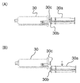
- FIG. 3 (A) is a diagram showing a connected state in which a long plunger of a small diameter syringe is connected
- FIG. 3 (B) is a diagram showing a disconnected state in which the long plunger of a small diameter syringe is disconnected.
- reference numeral 30a is a detachable long plunger
- 30c is a short plunger connected to the gasket of the small diameter syringe
- 30b is a long plunger connection that connects the long plunger 30a to the short plunger 30c. Indicates the part.
- FIG. 3 (A) is a diagram showing a connected state in which a long plunger of a small diameter syringe is connected
- FIG. 3 (B) is a diagram showing a disconnected state in which the long plunger of a small diameter syringe is disconnected.
- reference numeral 30a is a detachable long plunger
- 30c is a short plunger connected to the gasket of the small diameter
- FIG. 3 (A) shows a state in which a detachable long plunger 30a is connected to the small diameter syringe 30 and a short plunger 30c is connected to the small plunger 30c by a long plunger connecting portion 30b.
- FIG. 3B shows a state in which the long plunger 30a that is detachable from the small diameter syringe 30 is disconnected from the short plunger 30c, and the small diameter syringe 30 becomes only the short plunger 30c.
- FIG. 4 is a schematic view showing a state in which the outer peripheral warming heater is attached to the small diameter syringe and the contrast medium bottle.
- Reference numeral 10c denotes an outer peripheral warming heater for a small-diameter syringe
- 10d denotes an outer peripheral warming heater for a contrast medium bottle
- 10c2 and 10d2 denote heat source power cords to the respective outer peripheral warming heaters 10c and 10d.
- Reference numeral 70 is a contrast medium bottle
- 70a is a contrast medium filling line.
- FIG. 5 (A) is a reference diagram showing a state where a plunger that cannot be separated is connected to the pump head portion
- FIG. 5 (B) is a diagram showing a state in which the long plunger is separated in one embodiment of the present invention. It is a figure which shows the state by which the plunger of the separated state was connected to the pump head part.
- reference numeral 40 denotes a plunger used for a general syringe that cannot be separated.
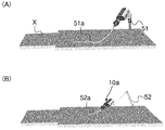
- FIG. 6 (A) is a reference diagram showing a state in which a general contrast medium injection device pump head is fixed to the catheter treatment table
- FIG. 6 (B) is an embodiment of the present invention. It is a figure which shows the state in which the pump head part was attached to the arm stand.
- reference symbol X is a catheter treatment table used in an X-ray environment
- 51 is a pump head of a general contrast medium injection device attached to a side rail of the catheter treatment table X.
- a fixed pole 51a for fixing is shown as a long-sized infusion extension tube extending long from the pump head attached to the fixed pole 51 to the surgical field.
- reference numeral 52 denotes an arm stand for mounting the pump head portion 10a of the present embodiment, and 52a is a short length from the pump head portion 10a moved to the vicinity of the surgical field by the arm stand 52.
- a short-sized injection extension tube is shown extending slightly.
- FIG. 7 (A) is a diagram showing a pump head portion with a built-in drive unit, which is an embodiment of the present invention
- FIG. 7 (B) is a diagram showing another embodiment of the present invention, where the drive unit is a pump. It is a figure which shows the pump head part of a drive part external type which is not incorporated in the head part.
- reference numeral 62 denotes a plunger drive unit that moves so as to move the plunger (short plunger 30c) of the small-diameter syringe 30, and 61 denotes a plunger drive unit 62 that is driven by a motor. The motor power unit to be moved is shown.
- FIG. 7 is a diagram showing a pump head portion with a built-in drive unit, which is an embodiment of the present invention
- FIG. 7 (B) is a diagram showing another embodiment of the present invention, where the drive unit is a pump. It is a figure which shows the pump head part of a drive part external type which is not incorporated in
- reference numeral 62 transmits the plunger drive unit to the plunger drive unit as in FIG. 7A, and 63 transmits the power of an external motor (not shown) to the plunger drive unit 62 to drive the plunger.
- a part of the flexible shaft (tube) for moving the part 62 is shown.
- FIG. 8 is a graph showing the effect comparison between using and not using a film heater for a contrast medium bottle in a heat insulation experiment.
- the horizontal axis indicates time, and the vertical axis indicates temperature (° C.).
- T1 is the elapsed temperature of the outer periphery of the contrast agent bottle when the outer peripheral heat retaining heater unit 10d for the contrast agent bottle is used
- T2 is the elapsed temperature of the outer periphery of the contrast agent bottle when the outer peripheral heat insulating heater unit 10d is not used.
- T3 indicates the environmental temperature.
- the injection system 100 of this embodiment includes a contrast medium injection device I and an injection control unit (pump control device) 10 f connected to the injection device I.
- an injection control unit pump control device 10 f connected to the injection device I.
- the injection system 100 is used to inject a contrast agent into a patient for catheter treatment.
- the injection system 100 includes a switch unit (operative field side hand switch unit) that performs an operation of injecting a contrast medium in the injection device I in addition to the injection device I and the injection control unit 10 f. 10b, an operative field side foot switch unit 10i, an operation room side hand switch unit 10g), a main unit 10k as a main power source, a relay box 10h connected to the main unit 10k, and the like.
- the injection system 100 is used in an operating room or the like, and a suspension stand (not shown) on which a catheter treatment table X (see FIG. 6) and a contrast medium bottle 70 (see FIG. 4) for performing treatment on a patient are suspended. )have.
- the injection system 100 injects a contrast medium into the patient's body by operating any one of the switch units 10b, 10i, and 10g and driving the injection device I by a motor. More specifically, the contrast medium in the small diameter syringe 30 is injected into the patient's body through the microcatheter 80a (see FIG. 2) connected to the injection apparatus I.
- the switch unit may perform not only the injection of the contrast medium but also the operation of filling the small diameter syringe 30 with the contrast medium.
- an injection operation switch S1 and a filling operation switch S2 may be provided in the operative field side switch unit 10b.
- the injection operation switch S1 has a safety button SB.
- the lever-shaped injection operation switch S1 can be operated, and erroneous operation can be prevented.
- the injection operation switch S1 is operated, a predetermined injection amount is injected at a set injection speed.
- the set injection amount is injected or the operation of the injection operation switch S1 is stopped, the injection of the contrast agent is stopped.
- the filling operation switch S2 By operating the filling operation switch S2, the small diameter syringe 30 is automatically filled with the contrast medium at a set speed.
- the small-diameter syringe 30 is completely filled with the contrast agent or the filling operation switch S2 is pressed again, the filling is completed.
- the configuration of the injection system 100 described above is merely an example, and the configuration of the injection system 100 is not limited to that illustrated in FIG. 1.
- the microcatheter 80a is directly connected to the injection device I (small-diameter syringe 30). However, the microcatheter 80a is indirectly connected via a short-sized injection extension tube 52a having a minimum length. 80a may be connected to the injection device I.
- the injection device I includes a pump head portion 10a and a small-diameter syringe 30 connected to the pump head portion 10a.
- the pump head portion 10a is an injector head that slides the plunger of the small-diameter syringe 30 and injects a contrast medium into the patient.
- the pump head portion 10 a of the present embodiment includes a housing 20 d, a syringe mounting portion 20 a that is provided in the housing 20 d and to which the small-diameter syringe 30 is connected, and a plunger ( And a plunger connecting portion 20b to which the short plunger 30c) is connected.
- the syringe mounting portion 20a is configured as a single type that holds a single small-diameter syringe 30 in the present embodiment.
- the structure of the syringe mounting portion 20a is not particularly limited as long as the small diameter syringe 30 can be mounted.
- the syringe mounting portion 20a can be configured to engage and lock the flange portion of the small diameter syringe 30.
- the structure of the plunger connecting portion 20b is not particularly limited as long as the short plunger 30c of the small diameter syringe 30 can be connected to the pump head portion 10a.
- the pump head portion 10 a has a heat source output terminal 20 c to which a heat source power cord 10 c 2 is connected in order to heat the outer heat retaining heater portion 10 c.
- the heat source output terminal 20c is provided in the vicinity of the connection portion with the small diameter syringe 30 on the side portion of the pump head portion 10a.
- the heat source power cord 10c2 has a plug-in connection portion that is inserted into the heat source output terminal 20c.
- the connection between the heat source power cord 10c2 and the heat source output terminal 20c can be performed in parallel with the connection between the plunger of the small diameter syringe 30 and the plunger connecting portion 20b. Further, since the heat source power cord 10c2 is connected to the heat source output terminal 20c of the pump head portion 10a, the heat source power cord 10c2 does not interfere with the catheter treatment procedure. That is, there is no need to consider the extra length of the heat source power cord 10c2, and when the pump head portion 10a or the catheter treatment table X is moved during the treatment, the heat source power cord 10c2 It moves with the catheter treatment table X.
- the heat source power cord 10c2 is used for the procedure as in the case where it is connected to a position other than the catheter treatment table X (for example, the main unit 10k). There is no such thing as coming in a disturbing position.
- the pump head portion 10 a is configured as a small pump head portion configured to hold a single small-diameter syringe 30.
- the pump head portion 10a is preferably a small pump head portion used for a syringe capacity of 50 cc or less, for example.
- the small pump head portion 10a has, for example, a weight of 500 to 3000 g, a width (a length in a direction perpendicular to the axial direction of the small diameter syringe 30), and a length (a length in the axial direction of the small diameter syringe 30). 150 to 250 mm (in a contracted state not including a syringe).
- the pump head part 10a is provided with the plunger drive part 62 for sliding the plunger of the small diameter syringe 30 as FIG. 7 (A) and (B) show.
- the pump head unit 10a may include a motor power unit 61 as shown in FIG.
- the plunger drive unit 62 is connected to a separately provided motor power unit (not shown) for operating the pump head unit 10a by a flexible shaft 63, and motor power
- the plunger driving unit 62 may be remotely driven by the driving force of the unit.
- the pump head unit 10 can be further reduced in weight and size.
- the injection system 100 of the present embodiment includes an arm stand 52 to which the pump head portion 10a is attached and the pump head portion 10a can be moved to the operative field.
- “move to the surgical field” means a position where the small-diameter syringe 30 can be directly connected to the microcatheter 80a or the vicinity of the wing portion 80b of the microcatheter 80a (for example, the length of the necessary extension tube).
- Means that the pump head part 10a can be moved to a position of 500 mm or less, more preferably 250 mm or less.
- the arm stand 52 in the present embodiment has a plurality of arms (two in FIG.
- the arm stand 52 is preferably composed of a thin arm that does not interfere with the visual field of the surgical field.
- the arm stand 52 is attached to the catheter treatment table X.
- the arm stand 52 is detachably attached to the side rail provided on the side of the catheter treatment table X by a mounting bracket or the like, and the position in the horizontal direction and the vertical direction is adjusted so as not to obstruct the catheter treatment of the practitioner. Move as you can.
- the arm stand 52 preferably has a lightweight and simple configuration that can be attached to the catheter treatment table X in a state where the pump head portion 10a and the small diameter syringe 30 are supported.
- the structure of the arm stand 52 is not particularly limited as long as it can be attached to the catheter treatment table X and can move to the surgical field or the vicinity of the surgical field.
- the catheter In catheter treatment, the catheter is operated while continuously moving the catheter treatment table X in order to align the X-ray irradiation part with the affected part of the patient. Therefore, when the arm stand 52 is attached to the catheter treatment table X, the pump head portion 10a and the small diameter syringe 30 move in conjunction with the catheter treatment table X. Therefore, the operability of the catheter is improved, and it is not necessary to provide an extra length of the injection extension tube in consideration of the movement of the catheter treatment table X, and it becomes easy to eliminate the injection extension tube and greatly shorten it.
- a small-diameter syringe 30 connected to the pump head portion 10a includes a cylindrical cylinder member and a plunger (long plunger) that is slidably inserted into the cylinder member. 30a and a short plunger 30c).
- the small diameter syringe 30 having a capacity of 30 cc to 50 cc and an inner diameter of the small diameter syringe 30 of 20 to 30 mm is used. More preferably, it is preferable that the small diameter syringe 30 is set to a 30 cc capacity determined from the maximum injection amount of the contrast medium in the microcatheter treatment. This maximum injection volume can be obtained from an example of a series of imaging methods (angio imaging and CT imaging) required in performing hepatic artery embolization, for example.
- the injection device I becomes small and lightweight. Therefore, it is possible to easily move the pump head portion 10a and the small-diameter syringe 30 to the surgical field or the vicinity of the surgical field using the arm stand 52. Therefore, a large-scale device such as one using a ceiling-suspended relatively large pump head is not necessary, and the introduction cost of the contrast medium warming and injecting system 100 can be reduced. Moreover, by using the small-diameter syringe 30, in addition to the improvement in operability, the contrast agent driving pressure can be reduced.
- the plunger of the small diameter syringe 30 is connected to the short plunger 30c and the short plunger 30c connected to the gasket of the small diameter syringe 30 as shown in FIGS. 3 (A) and 3 (B).
- a long plunger 30a is connected to the short plunger 30c by the long plunger connecting portion 30b.
- the connection method between the short plunger 30c and the long plunger 30a is not specifically limited, For example, it can connect by engagement etc.
- the small diameter syringe 30 can be brought into a connected state and a disconnected state by sliding the long plunger 30a in a direction perpendicular to the axial direction of the small diameter syringe 30 with respect to the short plunger 30c.
- the small diameter syringe 30 When manually filling the small diameter syringe 30 with the contrast medium, the small diameter syringe 30 can be manually filled with the contrast medium by setting the long plunger 30a to the short plunger 30c. . Further, when the small diameter syringe 30 is connected to the pump head portion 10a, the long plunger 30a may be switched to a disconnected state in which the long plunger 30a is disconnected from the short plunger 30c. As a result, manual filling is facilitated, and the long plunger 30a is cut off at the time of injection by the injection device I. As can be understood from FIGS. 5A and 5B, the pump head portion The axial length in a state where the 10a and the small-diameter syringe 30 are combined can be significantly shortened. This improves operability and facilitates catheter treatment procedures.
- the injection system 100 further includes outer peripheral heat retaining heater portions 10c and 10d attached to the outer periphery of the small-diameter syringe 30 and the outer periphery of the contrast agent bottle 70 suspended on the suspension stand.
- the outer peripheral warming heater 10c is connected to a heat source output terminal provided in the small pump head 10a. Accordingly, as described above, the connection between the heat source power cord 10c2 and the heat source output terminal 20c can be performed in parallel with the connection between the plunger of the small diameter syringe 30 and the plunger connection portion 20b. it can. Further, since the heat source power cord 10c2 is connected to the heat source output terminal 20c of the pump head portion 10a, the heat source power cord 10c2 does not interfere with the catheter treatment procedure.
- the heat source output terminal for the outer periphery heat retaining heater portions 10c and 10d may be provided in both the pump head portion 10a and the relay box 10h. In this case, a heat source can be secured from both the pump head portion 10a and the relay box 10h.
- the temperature of the contrast medium can be kept at a predetermined temperature.
- the injection pressure when injecting the contrast agent can be reduced and the injection pressure can be made constant.
- the catheter treatment can be performed continuously. Other procedures are required during the catheter treatment, and the catheter operation is temporarily interrupted. However, it is not necessary to reheat the contrast medium. Therefore, the treatment time can be shortened.
- the predetermined temperature is not particularly limited, but can be 37 to 50 ° C., for example.
- the predetermined temperature is preferably 40 to 50 ° C., more preferably 37 to 39 ° C.
- the outer peripheral heat retaining heater portions 10c and 10d are not particularly limited as long as the temperature of the contrast medium can be maintained at a predetermined temperature, but for example, a film heater using heat generated by energizing the conductive film is preferable.
- the small diameter syringe 30 and the contrast agent bottle 70 have flexibility to be able to be attached to the entire outer periphery. Thereby, when it winds around the small diameter syringe 30 and affixes, it does not become bulky and does not become obstructive in the case of catheter treatment.
- the outer periphery heat insulation heater parts 10c and 10d are the film heaters which have the softness
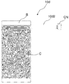
- the outer peripheral warming heater portions 10 c and 10 d include a flexible base material B having a flexible transparent conductive film C, a connector CN connectable to the heat source output terminal 20 c, The power source power cords 10c2 and 10d2 may be included.
- the base material B and the transparent conductive film C can be appropriately changed according to the object to be attached, that is, the size of the small diameter syringe 30 or the contrast agent bottle 70.
- the size of the outer peripheral warming heater portion 10c for the small-diameter syringe 30 can be set to 70 mm ⁇ 70 mm and the thickness is 0.2 mm when the small-diameter syringe 30 has a capacity of 10 cc. Is 30 mm, the thickness can be 70 mm ⁇ 100 mm and the thickness can be 0.2 mm.
- the size of the outer peripheral warming heater 10d for the contrast medium bottle 70 can be, for example, 85 mm ⁇ 185 mm and the thickness 0.2 mm when the capacity of the contrast medium bottle 70 is 100 cc.
- the applied voltage of the outer peripheral warming heater 10c for the small-diameter syringe 30 can be 1.5 to 3.0 V.
- the voltage can be 3.5 to 4.5V.
- the applied voltage of the outer peripheral warming heater 10d for the contrast medium bottle 70 can be set to 5.0 to 7.0 V when the capacity of the contrast medium bottle 70 is 100 cc.
- the outer peripheral warming heater portion 10c (for example, the size is 70 mm ⁇ 70 mm and the thickness is 0.2 mm) covering the entire small-diameter syringe 30.
- the target temperature of 37 to 50 ° C. can be achieved within 300 seconds.
- the outer temperature insulation heater portion 10c (for example, the size is 70 mm ⁇ 100 mm, the thickness is 0.2 mm) is 3.5V to 4.5V. By applying a voltage, the target temperature of 37 to 50 ° C. can be achieved within 300 seconds. Further, in the case of a contrast medium bottle 70 having a capacity of 100 cc at an environmental temperature of 25 to 27 ° C., an outer peripheral warming heater portion 10d that covers the entire contrast medium bottle 70 (for example, the size is 85 mm ⁇ 185 mm, the thickness is 0.2 mm).
- the target temperature of 37 to 50 ° C. can be achieved within 300 seconds.
- the contrast agent inside the container can be quickly heated by applying a predetermined voltage to the outer peripheral warming heater.
- the outer peripheral warming heaters 10c and 10d may be attached to cover the periphery of the small-diameter syringe 30 or the contrast medium bottle 70 by adhesion, such as double-sided tape, or around the small-diameter syringe 30 or the contrast medium bottle 70 by a surface fastener or the like. It may be pasted over.
- the outer peripheral warming heater units 10 c and 10 d may include a temperature sensor that monitors the outer peripheral temperature of the small-diameter syringe 30 and the outer peripheral temperature of the contrast agent bottle 70.
- the peripheral heat retaining heaters 10c and 10d are provided with temperature sensors, and the temperature of the contrast medium in the small diameter syringe 30 and the contrast medium bottle 70 is controlled by controlling the peripheral temperature of the small diameter syringe 30 and the contrast medium bottle 70 by the pump control device 10f. Can be controlled more accurately. Therefore, the injection pressure can be kept constant.
- the injection speed can be increased while reducing the injection pressure of the contrast medium within a predetermined range, and the set values such as the injection volume and the injection speed set by the pump control device 10f and the contrast medium actually injected
- the difference between the injection amount and the injection speed of the measured value can be greatly reduced, and the contrast medium can be injected with high accuracy.
- the pump control device 10f may be able to control the injection amount and the injection speed in addition to the heat retention temperature of the contrast agent.
- the pump control device 10f can control the heat retention temperature, the injection amount, and the injection speed of the contrast agent. Therefore, the contrast agent is adjusted to a predetermined optimum temperature, and the contrast medium is contrasted with the desired injection amount and injection rate. Agents can be injected.
- the pump control device 10f may be configured to change the injection rate in units of 0.1 ml / sec. In this case, it is possible to inject a contrast medium according to the patient's case or affected area.
- the small diameter syringe 30 is connected to the contrast medium filling line 70a (see FIG. 4).
- the long plunger 30a of the small-diameter syringe 30 is operated, and the contrast agent is filled into the small-diameter syringe 30 and the air is vented by a manual push-pull operation.
- the long plunger connecting portion 30b of the long plunger 30a is slid from the short plunger 30c in a direction perpendicular to the axial direction of the small-diameter syringe 30 and separated. .
- the small-diameter syringe 30 is brought into a disconnected state where the long plunger 30a is separated, the small-diameter syringe 30 is connected to the plunger connecting portion 20b as shown in FIG. 5B, and the pump head portion 10a and the small-diameter syringe are connected. 30 is connected.
- the outer peripheral warming heater portion 10c for the small diameter syringe and the outer peripheral warming heater portion 10d for the contrast agent bottle are attached to the small diameter syringe 30 and the contrast agent bottle 70, respectively.
- the power cords 10c2 and 10d2 are connected to the heat source output terminal 20c of the pump head portion 10a and the heat source output terminal of the relay box 10h, and the heat retention of the contrast agent is started.
- the syringe attachment fixing wing portion 80 b of the microcatheter 80 a is attached to the small diameter syringe 30.
- the injection of the contrast agent is started by the operation of any one of the hand switch units 10b and 10g or the foot switch unit 10i.
- injection system 100 is not limited to the above-described embodiment, and can be changed and added to various forms or sizes based on the spirit of the present invention, and these can be added from the scope of the present invention. It is not excluded.
- Fig. 8 shows two bottles (about 180 ml) with hot water heated to 37 ° C, and compares the two types of temperature transitions between those with and without film heaters. It is.
- Sato Corporation 3 channel thermometer data logger MTM-380SDJ As equipment to be used, Sato Corporation 3 channel thermometer data logger MTM-380SDJ, one wire temperature sensor TP-300 for environmental temperature measurement, and tape type multipurpose temperature sensor TS-04K for bottle temperature measurement ( Two sensors (width 4 mm ⁇ length 100 mm) were used.
- the one without the film heater decreases toward room temperature as time passes, whereas the film heater attached side also after 70 minutes. It can be seen that the initial temperature of 37 ° C is maintained. Therefore, it can be seen that the temperature of the contrast medium can be maintained at a predetermined temperature even when time elapses by using the film heater (outer peripheral heat retaining heater portion).
- Table 1 shows comparison data of injection pressures when the contrast medium is injected at room temperature and when the contrast medium is heated when the injection speed is changed every 0.1 ml / sec.
- Example> In a state where the microcatheter 80b was directly connected to the small diameter syringe 30, the injection pressure of the contrast medium under heating / non-heating (room temperature) was compared.
- the contrast medium is heated by winding a film heater around the outer circumference of the small-diameter syringe and measuring the outer temperature using the temperature sensor used for measuring the temperature transition in FIG. The film heater was controlled.
- the small-diameter syringe, contrast medium, temperature, and injection conditions used were as follows.
- Small diameter syringe Inner diameter 22.3mm, capacity 30cc ⁇ Contrast used: Iomeron 300 300 mg I / ml ⁇ Catheter used: Estream, tip outer diameter 0.68 mm / hand outer diameter 0.97 mm, 135 cm ⁇ Injection volume setting: Injection speed 0.1 to 2.3 ml / sec ⁇ Total injection volume: 3cc ⁇ Room temperature: 25 °C ⁇ Heating device: A film heater is wound around the outer circumference of a small-diameter syringe. ⁇ Warming temperature: 37 °C
- the injection pressure with the contrast medium under the heating condition is significantly lower than the contrast medium under the room temperature condition, and the difference in the high injection area is particularly large. It turns out that it is 2 or less. Therefore, it has been found that the injection pressure can be greatly reduced as compared with the conventional apparatus by using a small diameter syringe and heating the outer periphery of the small diameter syringe. In particular, it was found that when the injection rate was 1.3 to 2.3 ml / sec, the differential pressure was 100 PSI or more, and a significant effect was obtained.
- Table 2 shows an injection test example using a heating injection pressure at 37 ° C. at an injection rate of 1.5 ml / sec, 1.8 ml / sec, and 2.0 ml / sec in Table 1 and a general large-scale injection device ( Comparison data with medical device approval number: 21800BZZ10121000 (see page 4 of the attached document).
- the injection pressure of the injection system in this example is significantly lower than that of a large general injection device.
- the diameter of the catheter used is 0.68 mm at the tip outer diameter / 0.97 mm at the hand outer diameter and the length is 135 cm
- the catheter Masters used in the large-scale infusion device of the comparative example is The outer diameter is 0.68 mm / the outer hand diameter is 0.94 mm, and the length is 125 cm.
- the injection device is ZMA 700 model A (Seaman).
- the infusion pressure of the example has a very significant effect that the infusion pressure becomes half or more for a catheter of the same size even in the comparison under the condition that the length is 10 cm disadvantageous. I understood it.
- 2nd Embodiment has shown the example which applied the outer periphery heat retention heater part to the syringe for manual operation which accommodates the suspension of the anticancer agent used for embolization treatment, and a contrast agent.
- description of points common to the first embodiment will be omitted, and differences will be mainly described.
- Each configuration described in the second embodiment can be applied to the first embodiment, and each configuration described in the first embodiment can be applied to the second embodiment.
- a therapeutic suspension warming and infusion system 1000 for a microcatheter accommodates a microcatheter 80 a and a suspension of an anticancer agent and a contrast agent used for embolization treatment.
- a manual operation syringe 300 and a connection unit 90 to which the manual operation syringe 300 and the microcatheter 80a are connected are provided.
- an outer peripheral warming heater portion 10 cc is attached to the outer periphery of the manual operation syringe 300.
- the connecting portion 90 is attached to the injection device I and the small-diameter syringe 30 attached to the injection device I, and the manual operation syringe 300 can be connected.
- the injection device I and the small diameter syringe 30 are not limited to those used in the first embodiment, and may have other structures.
- As the manual operation syringe 300 a known manual operation syringe can be used.
- connection unit 90 is not limited to the illustrated structure as long as the manual operation syringe 300 can be connected.
- the connection unit 90 includes a three-way cock 90a that switches between a flow path from the manual operation syringe 300 to the microcatheter 80a, a flow path from the small diameter syringe 30 to the microcatheter 80a, and the contrast agent bottle 70.
- a connected contrast medium filling line 70a is connected, and is provided between the small diameter syringe 30 and the three-way stopcock 90a, which is opened when the small diameter syringe 30 is filled with the contrast medium and closed when the contrast medium is injected.
- a one-way valve 90c that closes when the contrast medium is filled and opens when the contrast medium is injected.
- the outer peripheral warming heater portion 10cc attached to the outer periphery of the syringe 300 for manual operation is heated by connecting the heat source cord 10cc2 to the heat source output terminal.
- the heat source output terminal may be provided in any device, but in this embodiment, as shown in FIG. 11, the heat source cord 10cc is connected to the heat source output terminal 20c provided in the pump head portion 10a. . In this case, for example, two heat source output terminals may be provided in the pump head portion 10a.
- the heat source power terminal 10c2 of the syringe 300 for manual operation is connected to the heat source output terminal 20c provided in the pump head portion 10a, so that the heat source power cord 10cc2 does not interfere with the catheter treatment technique, and the treatment site Can be continuously performed in the same field of view from the visualization of the image to embolization treatment.
- the outer peripheral warming heater portion 10cc is attached to the outer periphery of the manual operation syringe 300 as shown in FIGS.
- the outer periphery of the manual operation syringe 300 can be kept warm similarly to the outer peripheral heat retaining heater portion 10c attached to the small-diameter syringe 30 described in the first embodiment, and the temperature of the suspended medicine is set to a predetermined value.
- the predetermined temperature is not particularly limited, but can be 37 to 50 ° C., for example.
- the predetermined temperature is preferably 40 to 50 ° C., more preferably 37 to 39 ° C.
- the outer heat insulating heater 10 cc (for example, the size is 70 mm ⁇ 70 mm and the thickness is 0.2 mm) covering the entire syringe 300 is 1.
- the target temperature of 37 to 50 ° C. can be achieved within 300 seconds.
- a voltage of 3.5 V to 4.5 V is applied to the outer heat insulating heater 10 cc (for example, the size is 70 mm ⁇ 100 mm and the thickness is 0.2 mm).
- the target temperature of 37 to 50 ° C. can be achieved within 300 seconds.
- the suspension medicine inside a syringe can be heated rapidly by applying a predetermined voltage to an outer periphery heat retention heater part.
- the suspension drug is injected by the manually operated syringe 300 into a plurality of tumors of a patient and a plurality of nutritional blood vessels extending to the plurality of tumors.
- This treatment usually takes about 2 to 3 hours in total, and the suspension is infused at a plurality of points at intervals. Therefore, in the conventional heating method, it was necessary to repeat a very complicated operation between the clean surgical field and the unclean field, according to this embodiment, the complicated operation is basically unnecessary, and , Treatment time can be shortened.
- this point will be described in detail.
- Non-Patent Document 2 the suspension is heated using a water bath.
- (1) Put water (2L) into the water bath and turn on the power.
- (2) Aspirate appropriate amounts of anticancer agent and contrast agent with a syringe and separate them into turbid containers.
- (3) Move to the location where the water bath is installed.
- (4) Put the turbid container in the test tube rack and put it in the water bath.
- (5) Return to the treatment table.
- (6) Move to the water bath installation location.
- the needle is attached and detached alternately when sucking up the turbid liquid and attaching it to the microcatheter.
- the suspension medicine is taken out from the water bath, the suspension from the first embolization site to the next embolization site is suspended. Since the cloudy medicine cools, it is necessary to repeat the operation of leaving it in the water bath and taking out the required amount when necessary.
- the suspension medicine is maintained by the outer peripheral warming heater 10cc. In addition to being able to maintain the reduction of the injection pressure and perform easy injection, continuous heating to a plurality of embolic sites is also possible. Therefore, it is not necessary to perform a conventional complicated operation, the injection pressure is reduced, the injection is easy, and the treatment time can be shortened.
- the contrast medium warming / injecting system for microcatheter includes the contrast medium injecting device and the pump control device connected to the injecting device, and the contrast medium injecting device is a pump.
- a peripheral heat retaining heater that includes a head portion and a small diameter syringe connected to the pump head portion, and further includes an outer peripheral heat retaining heater portion that is attached to the outer periphery of the small diameter syringe. The part is connected to a heat source output terminal provided in the pump head part.
- the outer periphery of the small-diameter syringe can be kept warm by the outer periphery warming heater, and the temperature of the contrast medium can be kept at a predetermined temperature.
- the injection pressure when injecting the contrast agent can be reduced and the injection pressure can be made constant.
- the catheter treatment can be performed continuously. Other procedures are required during the catheter treatment, and the catheter operation is temporarily interrupted. However, it is not necessary to reheat the contrast medium. Therefore, the treatment time can be shortened.
- the contrast medium warming and injecting system according to aspect 2 of the present invention preferably further includes an arm stand to which the pump head part is attached and the pump head part can be moved to the operative field.
- the contrast agent can be directly injected into the microcatheter, and the injection pressure can be further reduced and the cost can be further reduced by eliminating or significantly shortening the injection extension tube (the injection extension tube is unnecessary or Reduction and elimination of contrast agent loss).
- the contrast medium heat-injection system according to aspect 3 of the present invention is preferably such that, in aspect 1 or 2, the pump control device can control the heat retention temperature, the injection amount, and the injection speed of the contrast medium.
- the contrast agent since the heat retention temperature, the injection amount, and the injection speed of the contrast agent can be controlled by the pump control device, the contrast agent is adjusted to a predetermined optimum temperature, and the desired injection amount is adjusted.
- the contrast agent can be injected at an injection rate.
- the contrast medium warming and injecting system according to aspect 4 of the present invention is configured such that the pump head unit is connected to the drive unit that operates the pump head unit by a flexible shaft, and the drive unit is driven. It is preferable that the pump head unit is remotely driven by force.
- the pump head unit can be further reduced in weight and size. As a result, the pump head can be smoothly moved to the surgical field by a more compact arm stand.
- the small-diameter syringe has a capacity of 30 cc to 50 cc, and the small-diameter syringe preferably has an inner diameter of 20 to 30 mm. .
- the syringe has a small capacity and an inner diameter, and can be suitably used for the above-described pump head portion, so that the injection pressure is reduced and the operability during movement by the arm stand is improved.
- the small-diameter syringe is set to a 30 cc capacity determined from the maximum injection amount of the contrast medium in the microcatheter treatment.
- the plunger of the small diameter syringe has a short plunger connected to the gasket of the small diameter syringe and a long plunger connected to the short plunger, and the plunger of the small diameter syringe is manually filled with the contrast agent in the small diameter syringe
- the long plunger is connected to the short plunger, and the long plunger is disconnected from the short plunger when the small diameter syringe is connected to the pump head. It is preferable that
- the minimum required syringe size 30 cc is determined by obtaining the maximum injection amount of the contrast medium in the microcatheter treatment, and the minimum plunger (short plunger) required for the injection / filling is determined. It is assembled.
- the synergistic effect of the heat retaining property by the outer peripheral warming heater part and the good mobility by the arm stand and the small pump head part improves the quantitative accuracy of the contrast agent and the injection pressure. Can be reduced.
- a small amount of high-precision high-speed injection can be performed easily and effectively while taking advantage of portable characteristics by improving the weight and size of the pump head portion of the injection device without requiring significant improvements to the control device or the like. This is possible, and is extremely advantageous for use at the site of use of the microcatheter. Further, in the case of a small moving type with the lightest weight configuration that adopts a remote drive system (externally attached to the motor unit) that leads the power source from outside by combining the mode 3 and the mode 5, the pump head unit is more compact. The mobility becomes better.
- a small-diameter syringe requires contradictory functions required for plunger operation (the plunger should be long when filling manually, but the plunger should be short when automatically filling or moving the pump head, etc. ), The conflicting requirements can be satisfied by using a detachable two-stage system.
- the contrast medium heat-injection system according to Aspect 7 of the present invention is the film heater utilizing the heat generated by energization of the conductive film in the outer heat-retaining heater part according to any one of Aspects 1 to 6,
- the temperature of the contrast medium can be maintained at a predetermined temperature while maintaining a small size and light weight of the small diameter syringe, and the inside of the syringe and the bottle is formed by the film heater formed of a transparent material. It becomes easy to confirm.
- the contrast medium warming and injecting system according to aspect 8 of the present invention is the contrast medium warming and injecting system according to any one of aspects 1 to 7, comprising a contrast medium bottle containing a contrast medium filled in a small diameter syringe. It is preferable that the 2nd outer periphery heat retention heater part is attached to the outer periphery of an agent bottle.
- the cooled contrast medium is not supplied to the small diameter syringe. Therefore, heating of the contrast agent can be promoted, and the temperature of the supplied contrast agent is stabilized.
- the outer peripheral warming heater unit of the aspect 9 of the present invention includes a temperature sensor that monitors the outer peripheral temperature of the small-diameter syringe and the outer peripheral temperature of the contrast medium bottle, It is preferable to control the outer peripheral temperature of the small diameter syringe and the contrast medium bottle.
- the temperature of the contrast medium in the small diameter syringe and the contrast medium bottle can be controlled more accurately. Therefore, the injection pressure can be kept constant. Therefore, the injection speed can be increased while reducing the injection pressure of the contrast medium within a predetermined range, and the injection volume and injection speed set by the pump control device, the injection volume of the contrast medium actually injected, and the injection The deviation from the speed can be greatly reduced, and the contrast medium can be injected with high accuracy.
- the contrast medium warming and injecting system according to aspect 10 of the present invention is the manual operation method for housing a microcatheter and a suspension of an anticancer agent and a contrast medium used for embolization treatment according to any of aspects 1 to 9.
- the suspension medicine is continuously warmed by the outer peripheral heat retaining heater.
- the reduction of the injection pressure is maintained and easy injection can be performed, and continuous administration to a plurality of embolization sites is possible. Therefore, it is not necessary to perform a conventional complicated operation, the injection pressure is reduced, the injection is easy, and the treatment time can be shortened.
- the therapeutic suspension infusion system for microcatheter of aspect 11 of the present invention includes a microcatheter, a manually operated syringe for storing a suspension of an anticancer agent and a contrast agent used for embolization treatment, and manual operation. And a connection portion to which the operation syringe and the microcatheter are connected, and an outer peripheral warming heater portion is attached to the outer periphery of the manual operation syringe.
- suspension medicine is continuously heated by an outer periphery heat retention heater part. Then, in addition to the reduction of the injection pressure being maintained, easy injection can be performed, and continuous administration to a plurality of embolic sites is possible. Therefore, it is not necessary to perform a conventional complicated operation, the injection pressure is reduced, the injection is easy, and the treatment time can be shortened.
- the outer peripheral warming heater part is a film heater using heat generated by energization of the conductive film, and the outer periphery of the manual operation syringe is moved to the entire circumference.
- it is preferably formed of a transparent material.
- the temperature of the suspension medicine can be maintained at a predetermined temperature while maintaining the reduction in size and weight of the manual operation syringe.
- the film heater formed of a transparent material can be used for the syringe. The inside can be easily checked.
- the outer peripheral warming heater unit includes a temperature sensor that monitors the outer peripheral temperature of the manual operation syringe, and the outer peripheral temperature of the manual operation syringe is controlled to a predetermined temperature. It is preferred that
- the temperature of the suspended drug in the manual operation syringe can be controlled more accurately. Therefore, the injection pressure can be kept constant. Therefore, the operation feeling of the syringe does not change while reducing the injection pressure of the suspension medicine to a predetermined range.
- the infusion system of each of the above-described embodiments is particularly concerned with the recent social problem of cancer treatment refugees, and as a countermeasure, embolization treatment (the embolization material is sent from a microcatheter to send cancer to the cancer).
- embolization treatment the embolization material is sent from a microcatheter to send cancer to the cancer.
- the possibility of use in the future is increasing, the simpler structure makes it relatively easy to make things, and the use improves functionality (reduction of injection pressure). (Higher accuracy of injection / injection volume) or labor saving (contrast agent loss and cost reduction of injection extension tube), etc., can be used well in terms of cost performance, and there is also a problem in terms of safety. Expectation for practical use is greater than it seems.
Landscapes
- Health & Medical Sciences (AREA)
- Life Sciences & Earth Sciences (AREA)
- Engineering & Computer Science (AREA)
- Veterinary Medicine (AREA)
- Animal Behavior & Ethology (AREA)
- Public Health (AREA)
- General Health & Medical Sciences (AREA)
- Biomedical Technology (AREA)
- Heart & Thoracic Surgery (AREA)
- Hematology (AREA)
- Anesthesiology (AREA)
- Vascular Medicine (AREA)
- Medical Informatics (AREA)
- Pathology (AREA)
- Surgery (AREA)
- Molecular Biology (AREA)
- Radiology & Medical Imaging (AREA)
- Biophysics (AREA)
- Physics & Mathematics (AREA)
- Optics & Photonics (AREA)
- Nuclear Medicine, Radiotherapy & Molecular Imaging (AREA)
- High Energy & Nuclear Physics (AREA)
- Infusion, Injection, And Reservoir Apparatuses (AREA)
- Apparatus For Radiation Diagnosis (AREA)
Abstract
Description
以下、添付図面を参照し、本発明の一実施形態のマイクロカテーテル用造影剤保温注入システムを説明する。なお、以下に説明する実施形態はあくまで一例であり、本発明の造影剤保温注入システムは、以下の実施形態に限定されるものではない。
以下に、本発明の注入システム100の注入圧力低減化への根幹となるマイクロカテーテルへの直接注入(ロングサイズの注入延長管51a(図6(A)参照)の不使用時)による注入圧に関する実験例につき、図8及び表1、2を用いて詳細に説明する。
小径シリンジ30にマイクロカテーテル80bを直接接続した状態にて、造影剤の加温・非加温下(室温)での注入圧力を比較した。造影剤の加温は、フィルムヒーターを小径シリンジの外周に巻き付け、図8の温度推移の測定に用いた、温度センサーを用いて外周温度を測定し、小径シリンジの外周が一定の温度となるように、フィルムヒーターを制御して行った。その他、使用した小径シリンジ、造影剤、温度、注入の条件は以下の通りであった。
・小径シリンジ:内径22.3mm、容量30cc
・使用造影剤:イオメロン300 300mgI/ml
・使用カテーテル:エストリーム、先端外径0.68mm/手元外径0.97mm、135cm
・注入量設定:注入速度0.1~2.3ml/sec
・トータル注入量:3cc
・室温:25℃
・加温装置:フィルムヒーターを小径シリンジの外周に巻き付け装着。
・加温温度:37℃


第2の実施形態は、外周保温ヒーター部を、塞栓治療に用いられる抗がん剤および造影剤の懸濁液を収容する手動操作用シリンジに適用した例を示している。以下の説明では、第1の実施形態と共通する点については説明を省略し、相違点を中心に説明する。なお、第2の実施形態で説明する各構成は、第1の実施形態に適用することができ、第1の実施形態で説明した各構成は、第2の実施形態に適用することができる。
(1)ウォーターバスに水(2L)を入れ電源をオンにする。
(2)抗がん剤および造影剤の適量をシリンジで吸引し、混濁容器に取り分ける。
(3)ウォーターバスの設置場所に移動する。
(4)混濁容器を試験管ラックに入れ、ウォーターバスに入れる。
(5)治療台へ戻る。
(6)ウォーターバスの設置場所に移動する。
(7)使用直前に混濁容器を取り出してシリンジにて1mlづつ小分け注入を行う。
(8)混濁液の吸い上げと、マイクロカテーテルへの取付時において交互に針の付け外しを行う。
1000 懸濁薬保温注入システム
10a ポンプヘッド部
10b 術野側ハンドスイッチ部
10c 小径シリンジ用の外周保温ヒーター部
10cc 手動操作用シリンジの外周保温ヒーター部
10c2 熱源用電源コード
10d 造影剤ボトル用の外周保温ヒーター部
10d2 熱源用電源コード
10e モータボックス
10f 注入制御部(ポンプ制御装置)
10g 操作室側ハンドスイッチ部
10h 中継ボックス
10i 術野側フットスイッチ部
10j モニター
10k メインユニット
10l、10m、10n、10o ケーブル
20a シリンジ装着部
20b プランジャー接続部
20c 熱源出力端子
20d 筐体
30 小径シリンジ
300 手動操作用シリンジ
30a 長プランジャー
30b 長プランジャー接続部
30c 短プランジャー
40 プランジャー
51 固定ポール
51a ロングサイズの注入延長管
52 アームスタンド
52a ショートサイズの注入延長管
61 モータ動力部
62 プランジャー駆動部
63 フレキシブルシャフト
70 造影剤ボトル
70a 造影剤充填ライン
80a マイクロカテーテル
80b シリンジ取り付け固定用ウイング部
90 接続部
90a 三方活栓
90b、90c 一方弁
B 基材
C 透明導電膜
CN コネクタ
I 注入装置
S1 注入操作スイッチ
S2 充填操作スイッチ
SB セーフティボタン
T1 外周保温ヒーター部の使用時における造影剤ボトルの外周の経過温度
T2 外周保温ヒーター部の不使用時における造影剤ボトルの外周の経過温度
T3 環境温度
X カテーテル治療台
Claims (13)
- 造影剤の注入装置と、該注入装置に接続するポンプ制御装置と、を具備するマイクロカテーテル用造影剤保温注入システムであって、
前記造影剤の注入装置が、ポンプヘッド部と、前記ポンプヘッド部に接続される小径シリンジとを備え、
前記造影剤保温注入システムが、
前記小径シリンジの外周に取り付けられる外周保温ヒーター部をさらに備え、
前記小径シリンジの外周に取り付けられる外周保温ヒーター部は、前記ポンプヘッド部に設けられた熱源出力端子に接続されることを特徴とする造影剤保温注入システム。 - 前記ポンプヘッド部が取り付けられ、前記ポンプヘッド部を術野へ移動可能なアームスタンドをさらに備える請求項1記載の造影剤保温注入システム。
- 前記ポンプ制御装置が、造影剤の保温温度、注入量及び注入速度を制御可能なものであることを特徴とする請求項1または2に記載の造影剤保温注入システム。
- 前記ポンプヘッド部が、前記ポンプヘッド部を動作させる駆動部に、フレキシブルシャフトにより接続され、前記駆動部の駆動力により前記ポンプヘッド部が遠隔駆動される請求項1~3のいずれか1項に記載の造影剤保温注入システム。
- 前記小径シリンジは、容量が30cc~50ccであり、前記小径シリンジの内径が20~30mmである請求項1~4のいずれか1項に記載の造影剤保温注入システム。
- 前記小径シリンジが、マイクロカテーテル治療における造影剤の1回最大注入量から割り出された30cc容量に設定され、
前記小径シリンジのプランジャーが、前記小径シリンジのガスケットに接続される短プランジャーと、前記短プランジャーに接続される長プランジャーとを備え、
前記小径シリンジのプランジャーが前記小径シリンジに造影剤を手動充填される際の、前記長プランジャーが前記短プランジャーに接続された接続状態と、前記小径シリンジを前記ポンプヘッド部に接続する際の、前記長プランジャーが前記短プランジャーから切り離された切り離し状態とで切り換え可能に構成されている請求項1~5のいずれか1項に記載の造影剤保温注入システム。 - 前記外周保温ヒーター部が、導電性フィルムへの通電により得られる発熱を利用したフィルムヒーターであり、前記小径シリンジ及び前記造影剤ボトルの外周部全周への貼着可能とする柔軟性を有すると伴に、前記小径シリンジ及び前記造影剤ボトルの内部を確認するために、透明材料により形成されている請求項1~6のいずれか1項に記載の造影剤保温注入システム。
- 前記造影剤保温注入システムが、前記小径シリンジに充填される造影剤が収容された造影剤ボトルを備え、前記造影剤ボトルの外周に、第2の外周保温ヒーター部が取り付けられている請求項1~7のいずれか1項に記載の造影剤保温注入システム。
- 前記外周保温ヒーター部および前記第2の外周保温ヒーター部が、前記小径シリンジの外周温度、及び、前記造影剤ボトルの外周温度を監視する温度センサーを備え、前記小径シリンジ及び前記造影剤ボトルの外周温度が所定の温度に制御されることを特徴とする請求項8に記載の造影剤保温注入システム。
- 前記造影剤保温注入システムが、マイクロカテーテルと、塞栓治療に用いられる抗がん剤および造影剤の懸濁液を収容する手動操作用シリンジと、前記小径シリンジの先端に取り付けられ、前記手動操作用シリンジおよび前記マイクロカテーテルが接続される接続部とを備え、
前記手動操作用シリンジの外周に、第3の外周保温ヒーター部が取り付けられている請求項1~9のいずれか1項に記載の造影剤保温注入システム。 - マイクロカテーテルと、塞栓治療に用いられる抗がん剤および造影剤の懸濁液を収容する手動操作用シリンジと、前記手動操作用シリンジおよび前記マイクロカテーテルが接続される接続部とを備え、前記手動操作用のシリンジの外周に、外周保温ヒーター部が取り付けられているマイクロカテーテル用治療懸濁薬保温注入システム。
- 前記外周保温ヒーター部が、導電性フィルムへの通電により得られる発熱を利用したフィルムヒーターであり、前記手動操作用シリンジの外周部全周への貼着可能とする柔軟性を有すると伴に、前記手動操作用シリンジの内部を確認するために、透明材料により形成されている請求項11に記載の懸濁薬保温注入システム。
- 前記外周保温ヒーター部が、前記手動操作用シリンジの外周温度を監視する温度センサーを備え、前記手動操作用シリンジの外周温度が所定の温度に制御されることを特徴とする請求項11または12に記載の懸濁薬保温注入システム。
Priority Applications (3)
| Application Number | Priority Date | Filing Date | Title |
|---|---|---|---|
| JP2018508945A JP6709276B2 (ja) | 2016-04-01 | 2017-03-13 | マイクロカテーテル用造影剤保温注入システムおよび治療懸濁薬保温注入システム |
| EP17774242.6A EP3437683A4 (en) | 2016-04-01 | 2017-03-13 | CONTRASTANT TEMPERATURE CONSERVATION AND INJECTION SYSTEM FOR MICROCATHETER AND THERAPY-SUSPENSION MEDICINE TEMPERATURE CONSERVATION AND INJECTION SYSTEM |
| US16/088,726 US20200297943A1 (en) | 2016-04-01 | 2017-03-13 | System for temperature-maintaining and injecting contrast medium for microcatheter and system for temperature-maintaining and injecting therapeutic suspension medicine for microcatheter |
Applications Claiming Priority (2)
| Application Number | Priority Date | Filing Date | Title |
|---|---|---|---|
| JP2016-083200 | 2016-04-01 | ||
| JP2016083200 | 2016-04-01 |
Publications (1)
| Publication Number | Publication Date |
|---|---|
| WO2017169698A1 true WO2017169698A1 (ja) | 2017-10-05 |
Family
ID=59964263
Family Applications (1)
| Application Number | Title | Priority Date | Filing Date |
|---|---|---|---|
| PCT/JP2017/010026 Ceased WO2017169698A1 (ja) | 2016-04-01 | 2017-03-13 | マイクロカテーテル用造影剤保温注入システムおよび治療懸濁薬保温注入システム |
Country Status (4)
| Country | Link |
|---|---|
| US (1) | US20200297943A1 (ja) |
| EP (1) | EP3437683A4 (ja) |
| JP (1) | JP6709276B2 (ja) |
| WO (1) | WO2017169698A1 (ja) |
Families Citing this family (3)
| Publication number | Priority date | Publication date | Assignee | Title |
|---|---|---|---|---|
| WO2021044055A1 (en) | 2019-09-05 | 2021-03-11 | Lonza Ltd | Device for receiving a container for a parenteral drug injection system and method for preheating injectable fluid |
| CN113288325A (zh) * | 2021-07-13 | 2021-08-24 | 西安交通大学医学院第二附属医院 | 一种心血管内科造影多功能辅助设备 |
| EP4186541B1 (en) * | 2021-11-30 | 2026-02-11 | Siemens Healthineers AG | A method for providing a temperature information regarding a contrast medium and a contrast media injection system |
Citations (6)
| Publication number | Priority date | Publication date | Assignee | Title |
|---|---|---|---|---|
| JP2001520905A (ja) * | 1997-10-24 | 2001-11-06 | インバサテック・インコーポレーテッド | 自動的な高/低圧切換え機能を備える血管造影用注射装置 |
| JP2004504075A (ja) * | 2000-03-24 | 2004-02-12 | ノボ ノルディスク アクティーゼルスカブ | 可撓性ピストンロッド |
| JP2006500087A (ja) * | 2002-08-02 | 2006-01-05 | リーベル − フラーシャイム カンパニー | 注入器 |
| JP2010279698A (ja) * | 2009-06-02 | 2010-12-16 | Qinghua Univ | 注射器用加熱装置 |
| JP2011224352A (ja) * | 2010-04-01 | 2011-11-10 | Nemoto Kyorindo:Kk | 医用照明装置およびそれを備えたシステム |
| JP2012523276A (ja) * | 2009-04-08 | 2012-10-04 | マリンクロッド エルエルシー | 使用インジケータを備える患者専用管類セットを有する多投与医療流体注入システム |
Family Cites Families (4)
| Publication number | Priority date | Publication date | Assignee | Title |
|---|---|---|---|---|
| US7094216B2 (en) * | 2000-10-18 | 2006-08-22 | Medrad, Inc. | Injection system having a pressure isolation mechanism and/or a handheld controller |
| US6699232B2 (en) * | 2001-03-01 | 2004-03-02 | Scimed Life Systems, Inc. | Fluid injection apparatus with improved contrast visualization |
| US20050182322A1 (en) * | 2004-02-17 | 2005-08-18 | Liebel-Flarsheim Company | Injector auto purge |
| US9211381B2 (en) * | 2012-01-20 | 2015-12-15 | Medical Solutions, Inc. | Method and apparatus for controlling temperature of medical liquids |
-
2017
- 2017-03-13 EP EP17774242.6A patent/EP3437683A4/en not_active Withdrawn
- 2017-03-13 US US16/088,726 patent/US20200297943A1/en not_active Abandoned
- 2017-03-13 WO PCT/JP2017/010026 patent/WO2017169698A1/ja not_active Ceased
- 2017-03-13 JP JP2018508945A patent/JP6709276B2/ja not_active Expired - Fee Related
Patent Citations (6)
| Publication number | Priority date | Publication date | Assignee | Title |
|---|---|---|---|---|
| JP2001520905A (ja) * | 1997-10-24 | 2001-11-06 | インバサテック・インコーポレーテッド | 自動的な高/低圧切換え機能を備える血管造影用注射装置 |
| JP2004504075A (ja) * | 2000-03-24 | 2004-02-12 | ノボ ノルディスク アクティーゼルスカブ | 可撓性ピストンロッド |
| JP2006500087A (ja) * | 2002-08-02 | 2006-01-05 | リーベル − フラーシャイム カンパニー | 注入器 |
| JP2012523276A (ja) * | 2009-04-08 | 2012-10-04 | マリンクロッド エルエルシー | 使用インジケータを備える患者専用管類セットを有する多投与医療流体注入システム |
| JP2010279698A (ja) * | 2009-06-02 | 2010-12-16 | Qinghua Univ | 注射器用加熱装置 |
| JP2011224352A (ja) * | 2010-04-01 | 2011-11-10 | Nemoto Kyorindo:Kk | 医用照明装置およびそれを備えたシステム |
Non-Patent Citations (1)
| Title |
|---|
| See also references of EP3437683A4 * |
Also Published As
| Publication number | Publication date |
|---|---|
| JPWO2017169698A1 (ja) | 2019-08-08 |
| US20200297943A1 (en) | 2020-09-24 |
| EP3437683A4 (en) | 2019-11-27 |
| EP3437683A1 (en) | 2019-02-06 |
| JP6709276B2 (ja) | 2020-06-10 |
Similar Documents
| Publication | Publication Date | Title |
|---|---|---|
| US11253645B2 (en) | Apparatuses, systems and methods for controlled delivery of therapeutics and related substances | |
| US11497565B2 (en) | Device drive for catheter procedure system | |
| JP6283350B2 (ja) | 胃腸内視鏡診療用視野の鮮明度を高めるシステムおよびこのシステムの作動方法 | |
| US6620130B1 (en) | Infusion systems and methods for introducing fluids into the body within a desired temperature range | |
| US20140135878A1 (en) | Method and Apparatus for Peritoneal Hypothermia and/or Resuscitation | |
| CN110681002A (zh) | 一种可远程控制的液体栓塞材料精密注射装置 | |
| WO2017169698A1 (ja) | マイクロカテーテル用造影剤保温注入システムおよび治療懸濁薬保温注入システム | |
| JP2012517298A (ja) | 低体温療法を導入する方法および装置 | |
| US20230083639A1 (en) | Systems, devices and methods for performing medical procedures in the intestine | |
| US7384391B2 (en) | Heated ovum pick up needle | |
| CN109173012A (zh) | 防划伤超滑导丝、其包覆方法及包覆设备 | |
| CN106540362B (zh) | 带加热功能的输注系统及其工作方法 | |
| US7144418B1 (en) | Method, and system for selective cerebral hypothermia | |
| Pancaldi et al. | Flow-driven magnetic microcatheter for superselective arterial embolization | |
| CN105664346A (zh) | 一种经t管胆道造影剂推注装置 | |
| WO2025227671A1 (zh) | 一种可注射自控温磁性水凝胶的磁热疗系统 | |
| CN110711007A (zh) | 一种经血管腔内保护性栓塞剂的注射装置 | |
| CN205598412U (zh) | 一种经t管胆道造影剂推注装置 | |
| CN212067366U (zh) | 一种可远程控制的液体栓塞材料精密注射装置 | |
| CN118454022B (zh) | 一种临床药物输送控速设备 | |
| Chapman et al. | Application of the HeartLander crawling robot for injection of a thermally sensitive anti-remodeling agent for myocardial infarction therapy | |
| CN118490937B (zh) | 一种输液保温护理控制装置 | |
| CN211798236U (zh) | 一种放射介入用动脉灌注装置 | |
| CN116271338A (zh) | 药物注射装置和方法 | |
| JP2002017747A (ja) | 加熱治療装置 |
Legal Events
| Date | Code | Title | Description |
|---|---|---|---|
| WWE | Wipo information: entry into national phase |
Ref document number: 2018508945 Country of ref document: JP |
|
| NENP | Non-entry into the national phase |
Ref country code: DE |
|
| WWE | Wipo information: entry into national phase |
Ref document number: 2017774242 Country of ref document: EP |
|
| ENP | Entry into the national phase |
Ref document number: 2017774242 Country of ref document: EP Effective date: 20181102 |
|
| 121 | Ep: the epo has been informed by wipo that ep was designated in this application |
Ref document number: 17774242 Country of ref document: EP Kind code of ref document: A1 |