WO2017169706A1 - 電子ミラー制御装置 - Google Patents
電子ミラー制御装置 Download PDFInfo
- Publication number
- WO2017169706A1 WO2017169706A1 PCT/JP2017/010062 JP2017010062W WO2017169706A1 WO 2017169706 A1 WO2017169706 A1 WO 2017169706A1 JP 2017010062 W JP2017010062 W JP 2017010062W WO 2017169706 A1 WO2017169706 A1 WO 2017169706A1
- Authority
- WO
- WIPO (PCT)
- Prior art keywords
- rear side
- vehicle
- line
- vanishing point
- display
- Prior art date
- Legal status (The legal status is an assumption and is not a legal conclusion. Google has not performed a legal analysis and makes no representation as to the accuracy of the status listed.)
- Ceased
Links
Images




Classifications
-
- B—PERFORMING OPERATIONS; TRANSPORTING
- B60—VEHICLES IN GENERAL
- B60R—VEHICLES, VEHICLE FITTINGS, OR VEHICLE PARTS, NOT OTHERWISE PROVIDED FOR
- B60R1/00—Optical viewing arrangements; Real-time viewing arrangements for drivers or passengers using optical image capturing systems, e.g. cameras or video systems specially adapted for use in or on vehicles
- B60R1/12—Mirror assemblies combined with other articles, e.g. clocks
-
- B—PERFORMING OPERATIONS; TRANSPORTING
- B60—VEHICLES IN GENERAL
- B60R—VEHICLES, VEHICLE FITTINGS, OR VEHICLE PARTS, NOT OTHERWISE PROVIDED FOR
- B60R1/00—Optical viewing arrangements; Real-time viewing arrangements for drivers or passengers using optical image capturing systems, e.g. cameras or video systems specially adapted for use in or on vehicles
- B60R1/006—Side-view mirrors, e.g. V-shaped mirrors located at the front or rear part of the vehicle
-
- B—PERFORMING OPERATIONS; TRANSPORTING
- B60—VEHICLES IN GENERAL
- B60R—VEHICLES, VEHICLE FITTINGS, OR VEHICLE PARTS, NOT OTHERWISE PROVIDED FOR
- B60R1/00—Optical viewing arrangements; Real-time viewing arrangements for drivers or passengers using optical image capturing systems, e.g. cameras or video systems specially adapted for use in or on vehicles
- B60R1/20—Real-time viewing arrangements for drivers or passengers using optical image capturing systems, e.g. cameras or video systems specially adapted for use in or on vehicles
- B60R1/22—Real-time viewing arrangements for drivers or passengers using optical image capturing systems, e.g. cameras or video systems specially adapted for use in or on vehicles for viewing an area outside the vehicle, e.g. the exterior of the vehicle
- B60R1/23—Real-time viewing arrangements for drivers or passengers using optical image capturing systems, e.g. cameras or video systems specially adapted for use in or on vehicles for viewing an area outside the vehicle, e.g. the exterior of the vehicle with a predetermined field of view
- B60R1/26—Real-time viewing arrangements for drivers or passengers using optical image capturing systems, e.g. cameras or video systems specially adapted for use in or on vehicles for viewing an area outside the vehicle, e.g. the exterior of the vehicle with a predetermined field of view to the rear of the vehicle
-
- B—PERFORMING OPERATIONS; TRANSPORTING
- B60—VEHICLES IN GENERAL
- B60R—VEHICLES, VEHICLE FITTINGS, OR VEHICLE PARTS, NOT OTHERWISE PROVIDED FOR
- B60R11/00—Arrangements for holding or mounting articles, not otherwise provided for
- B60R11/02—Arrangements for holding or mounting articles, not otherwise provided for for radio sets, television sets, telephones, or the like; Arrangement of controls thereof
- B60R11/0229—Arrangements for holding or mounting articles, not otherwise provided for for radio sets, television sets, telephones, or the like; Arrangement of controls thereof for displays, e.g. cathodic tubes
-
- G—PHYSICS
- G08—SIGNALLING
- G08G—TRAFFIC CONTROL SYSTEMS
- G08G1/00—Traffic control systems for road vehicles
- G08G1/16—Anti-collision systems
-
- G—PHYSICS
- G08—SIGNALLING
- G08G—TRAFFIC CONTROL SYSTEMS
- G08G1/00—Traffic control systems for road vehicles
- G08G1/16—Anti-collision systems
- G08G1/167—Driving aids for lane monitoring, lane changing, e.g. blind spot detection
-
- H—ELECTRICITY
- H04—ELECTRIC COMMUNICATION TECHNIQUE
- H04N—PICTORIAL COMMUNICATION, e.g. TELEVISION
- H04N7/00—Television systems
- H04N7/18—Closed-circuit television [CCTV] systems, i.e. systems in which the video signal is not broadcast
-
- H—ELECTRICITY
- H04—ELECTRIC COMMUNICATION TECHNIQUE
- H04N—PICTORIAL COMMUNICATION, e.g. TELEVISION
- H04N7/00—Television systems
- H04N7/18—Closed-circuit television [CCTV] systems, i.e. systems in which the video signal is not broadcast
- H04N7/181—Closed-circuit television [CCTV] systems, i.e. systems in which the video signal is not broadcast for receiving images from a plurality of remote sources
-
- B—PERFORMING OPERATIONS; TRANSPORTING
- B60—VEHICLES IN GENERAL
- B60R—VEHICLES, VEHICLE FITTINGS, OR VEHICLE PARTS, NOT OTHERWISE PROVIDED FOR
- B60R1/00—Optical viewing arrangements; Real-time viewing arrangements for drivers or passengers using optical image capturing systems, e.g. cameras or video systems specially adapted for use in or on vehicles
- B60R1/12—Mirror assemblies combined with other articles, e.g. clocks
- B60R2001/1253—Mirror assemblies combined with other articles, e.g. clocks with cameras, video cameras or video screens
-
- B—PERFORMING OPERATIONS; TRANSPORTING
- B60—VEHICLES IN GENERAL
- B60R—VEHICLES, VEHICLE FITTINGS, OR VEHICLE PARTS, NOT OTHERWISE PROVIDED FOR
- B60R2300/00—Details of viewing arrangements using cameras and displays, specially adapted for use in a vehicle
- B60R2300/30—Details of viewing arrangements using cameras and displays, specially adapted for use in a vehicle characterised by the type of image processing
- B60R2300/303—Details of viewing arrangements using cameras and displays, specially adapted for use in a vehicle characterised by the type of image processing using joined images, e.g. multiple camera images
-
- B—PERFORMING OPERATIONS; TRANSPORTING
- B60—VEHICLES IN GENERAL
- B60R—VEHICLES, VEHICLE FITTINGS, OR VEHICLE PARTS, NOT OTHERWISE PROVIDED FOR
- B60R2300/00—Details of viewing arrangements using cameras and displays, specially adapted for use in a vehicle
- B60R2300/30—Details of viewing arrangements using cameras and displays, specially adapted for use in a vehicle characterised by the type of image processing
- B60R2300/304—Details of viewing arrangements using cameras and displays, specially adapted for use in a vehicle characterised by the type of image processing using merged images, e.g. merging camera image with stored images
- B60R2300/305—Details of viewing arrangements using cameras and displays, specially adapted for use in a vehicle characterised by the type of image processing using merged images, e.g. merging camera image with stored images merging camera image with lines or icons
-
- B—PERFORMING OPERATIONS; TRANSPORTING
- B60—VEHICLES IN GENERAL
- B60R—VEHICLES, VEHICLE FITTINGS, OR VEHICLE PARTS, NOT OTHERWISE PROVIDED FOR
- B60R2300/00—Details of viewing arrangements using cameras and displays, specially adapted for use in a vehicle
- B60R2300/80—Details of viewing arrangements using cameras and displays, specially adapted for use in a vehicle characterised by the intended use of the viewing arrangement
- B60R2300/8066—Details of viewing arrangements using cameras and displays, specially adapted for use in a vehicle characterised by the intended use of the viewing arrangement for monitoring rearward traffic
Definitions
- the technology disclosed herein relates to an electronic mirror control device that controls display of a background image including a rear side surface of a vehicle imaged by an imaging unit.
- Patent Document 1 There has been proposed a device that displays images of a rear side and a rear side of a vehicle photographed by an in-vehicle camera on a display installed inside the vehicle (see Patent Document 1).
- Patent Document 1 the visibility of the driver is improved by partially compressing and displaying the image displayed on the display.
- the driver During driving of the vehicle, the driver needs to be able to grasp the driving space correctly and safely in any environment. If there is no indirect field of view visible on the door mirror that can be seen from the rear side of the vehicle or a display that displays the rear side of the vehicle, the driver must rotate the body or neck and turn the face back. You will see the back side. In this case, the driver can intuitively grasp where the visible rear side environment is located in the traveling environment. However, since the neck is rotated and the line of sight is moved, the side-viewing time becomes long.
- the side of the vehicle can be confirmed without rotating the body or neck, so the side-viewing time is shortened.
- it since it is not directly seen with eyes, it takes time to grasp the traveling environment from the indirect view.
- an aspect of the technology disclosed herein is mounted on a vehicle and captures a background image including a rear side surface of the traveling vehicle, and is captured by the imaging unit.
- a display unit for displaying the background image a calculation unit for calculating the position of the vanishing point from the background image, an extraction unit for extracting a rear side region in which the rear side surface of the vehicle is displayed in the background image,
- a display control unit that displays a vanishing point line that matches a straight line passing through the vanishing point in the rear side surface region.
- the vanishing point line that plays the role of the optical flow is displayed on the rear side surface area where no optical flow exists, so that the driver can travel from the indirect field of view displayed on the display unit. Can be grasped in a short time.
- FIG. 6 is a flowchart schematically showing still another example of the operation of the vehicle. It is a figure which shows the background image displayed on a display by the operation
- movement of FIG. 6 It is a figure which shows the display installed in the vehicle interior. It is a figure explaining the effective condition set by experiment. It is a figure explaining the invalid condition set by experiment. It is a figure which shows the experimental result of a 1st test subject. It is a figure which shows the experimental result of a 2nd test subject.
- FIG. 1 is a block diagram schematically showing the configuration of the vehicle of the present embodiment.
- the vehicle 100 is a four-wheeled vehicle, for example.
- the vehicle 100 includes cameras 210 and 220 (an example of an imaging unit), displays 310 and 320 (an example of a display unit), and an electronic control unit (ECU) 400.
- cameras 210 and 220 an example of an imaging unit
- displays 310 and 320 an example of a display unit
- ECU electronice control unit
- the camera 210 is attached to, for example, a door mirror on the right side of the vehicle 100 so that the optical axis of the camera 210 faces the rear of the vehicle 100.
- the camera 210 continuously captures a background image on the right rear side of the vehicle 100 including the rear side surface on the right side of the vehicle 100 every predetermined time (for example, 1/60 seconds).
- the camera 210 may be attached to the position where the right door mirror is attached, so that the optical axis of the camera 210 faces the rear of the vehicle 100, instead of the right door mirror.
- the camera 220 is attached to, for example, a left-side door mirror of the vehicle 100 so that the optical axis of the camera 220 faces the rear of the vehicle 100.
- the camera 220 continuously captures a background image on the left rear side of the vehicle 100 including the rear side surface of the left side of the vehicle 100 every predetermined time (for example, 1/60 seconds).
- the camera 220 may be attached to the position where the left door mirror is attached so that the optical axis of the camera 220 faces the rear of the vehicle 100 instead of the left door mirror.
- the display 310 is arranged on the right side in front of the driver's seat.
- the display 310 displays the latest background image among the background images on the right rear side of the vehicle 100 captured continuously every predetermined time (for example, 1/60 seconds) by the camera 210.
- the display 320 is disposed on the left side in front of the driver's seat.
- the display 320 displays the latest background image among the left rear background images of the vehicle 100 continuously captured by the camera 220 every predetermined time (for example, 1/60 seconds).
- the displays 310 and 320 include, for example, a liquid crystal display panel.
- the displays 310 and 320 are not limited to the liquid crystal display panel, and may include other display devices such as an organic EL (Electro Luminescence) panel.
- organic EL Electro Luminescence
- ECU 400 controls the overall operation of vehicle 100.
- ECU 400 includes a central processing unit (CPU) 410, a memory 420, and other peripheral circuits.
- the memory 420 is composed of, for example, a semiconductor memory such as a flash memory, a hard disk, or another storage element.
- the memory 420 includes a frame memory that temporarily stores background images captured by the cameras 210 and 220, a memory that stores programs, a memory that temporarily stores data, and the like.
- the memory 420 includes a single memory having an area for temporarily storing each background image captured by the cameras 210 and 220, an area for storing a program, and an area for temporarily storing data. May be.
- the CPU 410 functions as a calculation unit 411, an extraction unit 412, and a display control unit 413 by operating according to programs stored in the memory 420.
- the calculation unit 411 calculates the positions of vanishing points on the displays 310 and 320 from the background images captured by the cameras 210 and 220, respectively.
- the extraction unit 412 extracts a rear side area 316 (FIGS. 3 to 5 described later) on which the rear side of the right side of the vehicle 100 is displayed from the background image captured by the camera 210.
- the extraction unit 412 extracts a rear side area in which the left rear side of the vehicle 100 is displayed from the background image captured by the camera 220.
- the display control unit 413 displays the latest background images captured by the cameras 210 and 220 stored in the frame memories of the memory 420 on the displays 310 and 320, respectively.
- the display control unit 413 displays each background image captured by the cameras 210 and 220 on the displays 310 and 320
- the display control unit 413 reverses the left and right for display.
- an image reflected on the right door mirror is displayed on the display 310
- an image reflected on the left door mirror is displayed on the display 320.
- the functions of the calculation unit 411, the extraction unit 412, and the display control unit 413 will be described in detail later.
- FIG. 2 is a flowchart schematically showing an example of the operation of the vehicle 100.
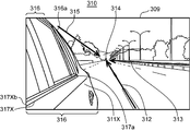
- FIG. 3 is a diagram illustrating an example of the background image 309 displayed on the display 310 while the vehicle 100 is stopped.
- FIG. 4 is a diagram for explaining the deformation of the background image 309.
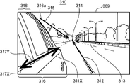
- FIG. 5 is a diagram illustrating an example of the background image 309 displayed on the display 310 while the vehicle 100 is traveling.
- the background image captured by the camera 210 will be described, but the same applies to the background image captured by the camera 220.
- step S ⁇ b> 201 the display control unit 413 displays the latest background image 309 captured by the camera 210 and stored in the frame memory of the memory 420 on the display 310.
- the vehicle 100 is stopped, and the display control unit 413 displays a background image 309 including the rear side surface 311 on the right side of the vehicle 100 captured by the camera 210 on the display 310.
- step S202 the vehicle 100 starts traveling.
- step S203 the calculation unit 411 calculates a first optical flow from the background image captured by the camera 210, and in step S204, calculates a second optical flow different from the first optical flow. To do.
- the optical flow is a vector representing the motion of an object in an image.
- the calculation unit 411 may extract feature points corresponding to each other from a plurality of background images, and calculate a line connecting the extracted corresponding feature points as the first and second optical flows.
- the calculation unit 411 may calculate the first and second optical flows using a known method such as the LucasKanade method or the Horn-Schunk method.
- FIG. 4 shows a first optical flow 312 and a second optical flow 313 that are not actually displayed on the display 310.
- step S ⁇ b> 205 the calculation unit 411 calculates an intersection point between the first optical flow 312 and the second optical flow 313 as a vanishing point 314.
- the vanishing point means a point where the lines intersect when drawing what is actually a parallel line so as not to be a parallel line in perspective.
- the intersection of the two optical flows 312 and 313 is calculated as the vanishing point 314.
- the calculation unit 411 further calculates a third optical flow 315 as shown in FIG. Also good.
- the calculation unit 411 may calculate the center of three intersections of the first to third optical flows 312, 313, and 315 as a vanishing point.
- the extraction unit 412 extracts the rear side area 316 where the rear side surface 311 of the vehicle 100 is displayed on the display 310.
- the extraction unit 412 may extract the rear side surface region 316 by a template matching method.
- the extraction unit 412 may compare each pixel value of a plurality of background images captured every predetermined time by the camera 210 and extract a region where the pixel value does not change as the rear side surface region 316.
- the ECU 400 may include a camera control unit that changes the angle of the optical axis of the camera 210 in accordance with the operation of the driver so that the imaging range of the camera 210 can be changed.
- the memory 420 may store data in which the angle of the optical axis of the camera 210 is associated with the rear side surface region 316.
- the extraction unit 412 acquires the current optical axis angle of the camera 210 from the camera control unit, and extracts the rear side surface region 316 associated with the acquired optical axis angle from the memory 420. Good.
- step S207 the display control unit 413 extracts the belt line 317 in the rear side surface region 316 extracted in step S206.
- the belt line 317 is a line that runs in the horizontal direction at the lower end of the side window of the vehicle body.
- the belt line 317 is a line that partitions the upper and lower parts of the vehicle body at the position of the window, and the upper end line of the lower vehicle body that runs in the horizontal direction along the door. It is.
- the image data of the belt line 317 may be stored in the memory 420 in advance.
- the display control unit 413 may extract the belt line 317 by the template matching method using the image data of the belt line 317 stored in the memory 420 as a template.
- the memory 420 includes the angle of the optical axis of the camera 210 and the belt line 317.
- the associated data may be stored.
- the display control unit 413 acquires the current optical axis angle of the camera 210 from the camera control unit, and extracts the belt line 317 associated with the acquired optical axis angle from the memory 420. Good.
- step S208 the display control unit 413 deforms the image of the rear side surface region 316 so that the belt line 317 matches a straight line passing through the vanishing point 314.
- the display control unit 413 first fixes the rear end 317a of the belt line 317, rotates the belt line 317 so that the belt line 317 coincides with a straight line passing through the rear end 317a and the vanishing point 314, and Then, the belt line 317 is stretched so that the front end 317 b coincides with the outer edge of the display 310.
- a converted belt line 317X (an example of a vanishing point line) having a rear end 317a and a front end 317Xb and matching a straight line passing through the vanishing point 314 is obtained.
- the display control unit 413 maintains the linearity of each pixel in the rear side surface region 316 with the boundary line 316a fixed, and the rear side surface so that the belt line 317 matches the belt line 317X. Region 316 is rotated and reduced or rotated and enlarged.
- the display control unit 413 obtains a transformation matrix of affine transformation for transforming the belt line 317 to the belt line 317X from the correspondence before and after the transformation of a plurality of points on the belt line 317 and the belt line 317X. . Further, the display control unit 413 performs coordinate conversion of the entire rear side surface 311 displayed in the rear side surface region 316 using the obtained conversion matrix in a state where the boundary line 316a of the rear side surface region 316 is fixed. Further, the display control unit 413 interpolates the pixels having gaps by the coordinate conversion using the data of surrounding pixels.
- the rear side surface 311 ⁇ / b> X after the coordinate conversion including the belt line 317 ⁇ / b> X coinciding with the straight line passing through the vanishing point 314 is displayed in the rear side region 316 by step S ⁇ b> 208 including the above procedure.
- step S203 Thereafter, the process returns to step S203, and the above steps are repeated. Note that the operation of FIG. 2 may end when the vehicle 100 stops.
- the rear side region 316 is coordinate-transformed so that the belt line 317X coincides with a straight line passing through the vanishing point 314.
- a belt line 317X that matches the straight line passing through the vanishing point 314, which plays the same role as the optical flow, is displayed in the rear side surface region 316 where no optical flow exists.
- the driver can grasp the traveling environment such as the position of the own vehicle in a short time when looking at the display 310.
- the display control unit 413 performs coordinate conversion on the rear side surface region 316 so that the belt line 317 coincides with a straight line passing through the vanishing point 314, but the display control unit 413 replaces the belt line 317.
- 413 may coordinate-transform the rear side surface area
- FIG. 3 is a line formed by intersecting surfaces configured as a vehicle design, or a line added as a vehicle design on the surface of a smooth vehicle body.
- the display control unit 413 only performs coordinate conversion of the rear side surface region 316 so that the belt line 317X is obtained, but is not limited thereto.
- FIG. 6 is a diagram showing a different example of the background image 309 displayed on the display 310 while the vehicle 100 is traveling.
- the display control unit 413 converts the coordinates of the rear side surface region 316 so that a belt line 317X that matches the straight line passing through the vanishing point 314 is obtained, and then passes through the vanishing point 314 on the belt line 317X.
- An arrow 317Y coinciding with is displayed.
- the display control unit 413 may display a line segment image 318 as shown in FIG.
- the rear side surface 311X having no sense of incongruity is displayed in the rear side surface region 316 by performing coordinate conversion using a transformation matrix of affine transformation, but is not limited thereto.
- FIG. 7 is a view showing still another example of the background image 309 displayed on the display 310 while the vehicle 100 is traveling.
- the display control unit 413 obtains the belt line 317X by the method described with reference to FIG. As a result, the window and the like above the belt line 317 (FIG. 3) remain in the state shown in FIG. 3, and the lower part is removed from the position of the belt line 317X. Further, the display control unit 413 interpolates the area between the belt line 317X and the character line 311Y below with the pixel data between the belt line 317 (FIG. 3) and the character line 311Y.
- FIG. 8 is a flowchart schematically showing different examples of the operation of the vehicle 100.
- FIG. 9 is a diagram showing a background image 309 displayed on the display 310 in the operation of FIG. Steps S201 to S206 in FIG. 8 are the same as steps S201 to S206 in FIG.
- step S501 following step S206 the display control unit 413 displays a line segment image 318 (an example of a vanishing point line) that overlaps the rear side surface region 316 extracted in step S206 and matches a straight line passing through the vanishing point 314. To do.
- a line segment image 318 an example of a vanishing point line
- the display control unit 413 arranges the rear end 318a of the line segment image 318 at an arbitrary position on the boundary line 316a of the rear side surface region 316.
- the display control unit 413 passes the rear end 318a of the line segment image 318 on the boundary line 316a so as to coincide with a straight line passing through the rear end of the belt line 317 and passing through the vanishing point 314. Is arranged.
- the display control unit 413 arranges the front end 318 b of the line segment image 318 on the outer edge of the display 310. Further, the display control unit 413 gradually increases the width of the line segment image 318 from the rear end 318a to the front end 318b so that a sense of perspective appears.
- the display control unit 413 displays the rear side surface 311 of the vehicle 100 on the display 310 while being imaged by the camera 210 as in FIG. 3.
- the process returns to step S203, and the above steps are repeated. Note that the operation of FIG. 8 may end when the vehicle 100 stops.
- the line segment image 318 that matches the straight line passing through the vanishing point 314 that plays the same role as the optical flow is displayed in the rear side surface region 316 where no optical flow exists.
- the driver can grasp the traveling environment such as the position of the own vehicle in a short time when looking at the display 310.
- FIG. 10 is a flowchart schematically showing still another example of the operation of the vehicle 100.
- FIG. 11 is a diagram showing a background image 309 displayed on the display 310 in the operation of FIG. Steps S201 to S206 in FIG. 10 are the same as steps S201 to S206 in FIG.
- step S701 following step S206 the display control unit 413 displays a vehicle silhouette 319 instead of the rear side surface of the vehicle 100 in the rear side region 316 extracted in step S206, as shown in FIG.
- the display control unit 413 may display an image in which the rear side surface region 316 is filled with, for example, a solid color as the silhouette 319.
- the subsequent step S501 is the same as step S501 in FIG. Thereafter, the process returns to step S203, and the above steps are repeated. Note that the operation of FIG. 10 may end when the vehicle 100 stops.
- the line segment image 318 that matches the straight line passing through the vanishing point 314 that plays the same role as the optical flow is displayed in the rear side surface region 316 where no optical flow exists.
- the driver can grasp the traveling environment such as the position of the own vehicle in a short time when looking at the display 310.
- a vehicle silhouette 319 is displayed in the rear side region 316 instead of the rear side of the vehicle 100. Therefore, the contrast of the line segment image 318 is increased, and the line segment image 318 can be made conspicuous.
- the line segment image 318 extends from the boundary line 316a of the rear side surface region 316 to the outer edge of the display 310, but is not limited thereto.
- the line segment image 318 may be displayed on a part of the rear side surface region 316. That is, the line segment image displayed so as to overlap the rear side surface region 316 may be shorter than the line segment image 318 shown in FIGS.
- the length of the line segment image 318 may be such that the driver's attention can be drawn.
- the detection time of light spots (target stimuli) presented to the left and right of the fixed viewpoint is measured following the cue stimulus.
- the experiment is operated by a cue, and a valid condition in which the cue indicates the spatial position of the target and an invalid condition in which the cue does not indicate the spatial position of the target are set.
- FIG. 12 is a diagram showing the display 310 installed in the room of the vehicle 100.
- FIG. 13 is a diagram for explaining effective conditions set in the experiment.
- FIG. 14 is a diagram for explaining invalid conditions set in an experiment.
- the experiment was conducted on a vehicle running on a straight road at a speed of 100 km / h.
- the display 310 is disposed on the instrument panel 500 and slightly to the right of the handle 501.
- a vehicle silhouette is displayed in the rear side region 316 instead of the rear side of the vehicle.
- a light emitting diode (LED) indicating the fixation point 510 is lit in the rear side surface region 316, and a line segment image 550 is displayed.
- LED light emitting diode
- an LED to be lit is taught to the subject as a cue stimulus.
- the LED 530 ahead of the fixation point 510 is turned on.
- the subject's attention is directed to a region 520 ahead of the fixation point 510.
- the subject moves his / her line of sight to the fixation point 510.
- the target stimulus is displayed. Thereafter, the subject answers the displayed position of the target stimulus.
- the LED 530 ahead of the fixation point 510 is lit as a target stimulus.
- the subject can immediately answer the position of the target stimulus.
- the LED 540 behind the fixation point 510 is lit as a target stimulus. That is, in the invalid condition, the subject moves the attention from the area 520 to the LED 540 and then answers the position of the target stimulus.
- reaction time under the effective condition is T1
- reaction time under the invalid condition is T2
- (T2-T1) is the time required for attention transfer. That is, as this (T2-T1) is shorter, attention can be moved more smoothly.
- the direction of the line segment image 550 was changed, and (T2-T1) was compared.
- FIG. 15 is a diagram showing an experimental result of the first subject A.
- FIG. 16 is a diagram showing an experimental result of the second subject B. In FIG. 15 and FIG. 16, the average values of experiments performed three times are shown.
- the first subject A has the shortest (T2-T1) when the line segment image 550 matching the line segment image 318 (FIG. 9) is displayed.
- the second subject B also has the shortest (T2-T1) when the line segment image 550 that matches the line segment image 318 (FIG. 9) is displayed.
- the line segment image 318 (FIG. 9) is displayed in the rear side surface region 316, so that the driver can view the driving environment such as the position of the vehicle when viewing the display 310. It was found that it can be grasped in a short time.
- the calculation unit 411 calculates the intersection of the optical flows 312 and 313 as the vanishing point 314, but the method for calculating the position of the vanishing point 314 is not limited to this.
- the calculation unit 411 detects, from one background image 309, two straight lines among a straight line representing a road edge such as a shoulder or a median, a boundary line representing a lane boundary, and the like. The intersection of the two detected straight lines may be calculated as the vanishing point.
- One aspect of the technology disclosed herein is an imaging unit that is mounted on a vehicle and that captures a background image including a rear side surface of the traveling vehicle, and a display unit that displays the background image captured by the imaging unit
- a calculation unit that calculates the position of the vanishing point from the background image
- an extraction unit that extracts a rear side region in which the rear side surface of the vehicle is displayed in the background image, and a vanishing point that matches a straight line passing through the vanishing point
- a display control unit that displays a dot line in the rear side surface region.
- the position of the vanishing point is calculated from the background image captured by the imaging unit.
- a rear side area in which the rear side of the vehicle is displayed in the background image is extracted.
- a vanishing point line coinciding with a straight line passing through the vanishing point is displayed in the rear side area.
- the vanishing point line that plays the role of optical flow is displayed in the rear side surface area where no optical flow exists.
- a belt line or a character line is provided on the rear side surface of the vehicle imaged by the imaging unit, and the display control unit displays the rear side surface of the vehicle imaged by the imaging unit.
- the belt line or character line is deformed so that the belt line or character line coincides with a straight line passing through the vanishing point, and the deformed belt line or character line is displayed.
- the vanishing point line may be displayed.
- the belt line or the character line is deformed and deformed so as to coincide with a straight line passing through the vanishing point.
- a belt line or a character line is displayed as a vanishing point line. Therefore, the belt line or character line provided on the rear side of the vehicle plays a role of optical flow. As a result, the driver can grasp the driving environment in a natural manner by using a familiar belt line or character line.
- the display control unit may display a line segment image that matches a straight line passing through the vanishing point as the vanishing point line in the rear side surface region.
- a line segment image that matches a straight line passing through the vanishing point is displayed as a vanishing point line in the rear side area. For this reason, a line segment image that plays the role of optical flow is displayed as a vanishing point line in the rear side surface area where no optical flow exists.
- the driver can grasp the traveling environment in a short time from the indirect field of view displayed on the display unit.
- the display control unit may display the silhouette of the vehicle in the rear side area instead of the rear side of the vehicle.
- the silhouette of the vehicle is displayed in the rear side area instead of the rear side of the vehicle. For this reason, the line segment image displayed in the rear side surface region as the vanishing point line can be made conspicuous.
Landscapes
- Engineering & Computer Science (AREA)
- Multimedia (AREA)
- Mechanical Engineering (AREA)
- Physics & Mathematics (AREA)
- General Physics & Mathematics (AREA)
- Signal Processing (AREA)
- Closed-Circuit Television Systems (AREA)
- Traffic Control Systems (AREA)
- Fittings On The Vehicle Exterior For Carrying Loads, And Devices For Holding Or Mounting Articles (AREA)
Abstract
電子ミラー制御装置は、車両に搭載され、走行中の前記車両の後側面を含む背景画像を撮像する撮像部と、撮像部により撮像された背景画像を表示する表示部と、背景画像から消失点の位置を算出する演算部と、背景画像において車両の後側面が表示された後側面領域を抽出する抽出部と、消失点を通る直線に一致する消失点ラインを後側面領域に表示する表示制御部と、を備える。
Description
ここに開示された技術は、撮像部により撮像された車両の後側面を含む背景画像の表示を制御する電子ミラー制御装置に関するものである。
従来、車載カメラで撮影された車両の後側面及び後側方の画像を車両内部に設置されたディスプレイに表示する装置が提案されている(特許文献1参照)。特許文献1に記載の技術では、ディスプレイに表示される画像を部分的に圧縮して表示することにより、運転者の視認性を向上させている。
車両の走行中には、いかなる環境においても、運転者は、走行空間を正しく安全に把握することができる必要がある。車両の後側方を視認できるドアミラー又はカメラで撮像した車両の後側方を表示するディスプレイに見える間接視界がない場合には、運転者は、体または首を回転させ、顔を後ろに向けて後側方を見ることになる。この場合には、運転者は、見えている後側方の環境が、走行環境のなかのどこに位置するかを直感的に把握することができる。しかしながら、首を回転したり視線を移動したりするため、わき見の時間が長くなってしまう。
これに対して、上記ドアミラー又はディスプレイに見える間接視界を利用した場合には、体又は首を回転せずに車両の後側方を確認することができるため、わき見の時間は短縮される。しかしながら、目で直接見ているわけではないため、間接視界から走行環境を把握するまでに時間を要してしまう。
そこで、間接視界を利用した場合でも、間接視界から自車の位置関係などの走行環境を短時間で把握できるようにすることが求められる。しかし、上記特許文献1では、この点について十分に検討されていない。
ここに開示された技術は、間接視界から走行環境を短時間で把握できるようにすることを目的とする。
上述の課題を解決するために、ここに開示された技術の一態様は、車両に搭載され、走行中の前記車両の後側面を含む背景画像を撮像する撮像部と、前記撮像部により撮像された前記背景画像を表示する表示部と、前記背景画像から消失点の位置を算出する演算部と、前記背景画像において前記車両の後側面が表示された後側面領域を抽出する抽出部と、前記消失点を通る直線に一致する消失点ラインを前記後側面領域に表示する表示制御部と、を備えるものである。
この電子ミラー制御装置によれば、オプティカルフローの存在しない後側面領域に、オプティカルフローの役割を果たす消失点ラインを表示することにより、運転者は、表示部に表示される間接視界から、走行環境を短時間で把握することが可能となる。
以下、図面を参照しつつ、本開示の実施形態が説明される。なお、各図では、同様の要素には同様の符号が付され、適宜、説明が省略される。
図1は、本実施形態の車両の構成を概略的に示すブロック図である。車両100は、例えば4輪自動車である。車両100は、図1に示されるように、カメラ210,220(撮像部の一例)、ディスプレイ310,320(表示部の一例)、電子制御ユニット(ECU)400を備える。
カメラ210は、例えば車両100の右側のドアミラーに、カメラ210の光軸が車両100の後方を向くように取り付けられる。カメラ210は、車両100の右側の後側面を含む車両100の右後方の背景画像を所定時間(例えば1/60秒)毎に連続して撮像する。なお、カメラ210は、右側のドアミラーに代えて、右側のドアミラーが取り付けられていた位置に、カメラ210の光軸が車両100の後方を向くように取り付けられてもよい。
カメラ220は、例えば車両100の左側のドアミラーに、カメラ220の光軸が車両100の後方を向くように取り付けられる。カメラ220は、車両100の左側の後側面を含む車両100の左後方の背景画像を所定時間(例えば1/60秒)毎に連続して撮像する。なお、カメラ220は、左側のドアミラーに代えて、左側のドアミラーが取り付けられていた位置に、カメラ220の光軸が車両100の後方を向くように取り付けられてもよい。
ディスプレイ310は、運転席の前方の右寄りに配置される。ディスプレイ310は、カメラ210により所定時間(例えば1/60秒)毎に連続して撮像された車両100の右後方の背景画像のうち最新の背景画像を表示する。ディスプレイ320は、運転席の前方の左寄りに配置される。ディスプレイ320は、カメラ220により所定時間(例えば1/60秒)毎に連続して撮像された車両100の左後方の背景画像のうち最新の背景画像を表示する。
ディスプレイ310,320は、例えば液晶表示パネルを含む。ディスプレイ310,320は、液晶表示パネルに限られず、有機EL(Electro Luminescence)パネルなどの他の表示デバイスを含んでもよい。
ECU400は、車両100の全体の動作を制御する。ECU400は、中央演算処理装置(CPU)410、メモリ420、その他の周辺回路を含む。メモリ420は、例えば、フラッシュメモリなどの半導体メモリ、ハードディスク、又は他の記憶素子で構成される。メモリ420は、カメラ210,220により撮像された各背景画像を一時的に保存するフレームメモリ、プログラムを保存するメモリ、データを一時的に保存するメモリ等を含む。なお、メモリ420は、カメラ210,220により撮像された各背景画像を一時的に保存する領域、プログラムを保存する領域、データを一時的に保存する領域を備えた単一のメモリで構成されていてもよい。
CPU410は、メモリ420に保存されているプログラムに従って動作することにより、演算部411、抽出部412、表示制御部413として機能する。演算部411は、カメラ210,220により撮像された各背景画像から、ディスプレイ310,320における消失点の位置をそれぞれ算出する。
抽出部412は、カメラ210により撮像された背景画像から、車両100の右側の後側面が表示された後側面領域316(後述の図3~図5)を抽出する。抽出部412は、カメラ220により撮像された背景画像から、車両100の左側の後側面が表示された後側面領域を抽出する。
表示制御部413は、メモリ420の各フレームメモリに保存された、カメラ210,220により撮像された最新の各背景画像をディスプレイ310,320にそれぞれ表示する。表示制御部413は、カメラ210,220により撮像された各背景画像をディスプレイ310,320に表示する際に、左右を反転して表示する。これによって、ディスプレイ310に右側のドアミラーに映る画像が表示され、ディスプレイ320に左側のドアミラーに映る画像が表示される。演算部411、抽出部412、表示制御部413の機能は、後に詳述される。
図2は、車両100の動作の一例を概略的に示すフローチャートである。図3は、車両100の停止中にディスプレイ310に表示される背景画像309の一例を示す図である。図4は、背景画像309の変形を説明する図である。図5は、車両100の走行中にディスプレイ310に表示される背景画像309の一例を示す図である。なお、以下では、カメラ210により撮像された背景画像について説明されるが、カメラ220により撮像された背景画像についても同様である。
例えばエンジンが始動されると、カメラ210により撮像が開始されて、図2の動作が開始される。ステップS201において、表示制御部413は、カメラ210により撮像され、メモリ420のフレームメモリに保存された最新の背景画像309をディスプレイ310に表示する。図3では、車両100は停止しており、表示制御部413は、カメラ210により撮像された車両100の右側の後側面311を含む背景画像309をディスプレイ310に表示している。
次に、ステップS202において、車両100は走行を開始する。次に、ステップS203において、演算部411は、カメラ210により撮像された背景画像から第1のオプティカルフローを算出し、ステップS204において、第1のオプティカルフローとは別の第2のオプティカルフローを算出する。
オプティカルフローは、画像中の物体の動きをベクトルで表したものである。演算部411は、複数の背景画像から、それぞれの間で互いに対応する特徴点を抽出し、抽出した対応する特徴点を結んだ線を第1、第2のオプティカルフローとして算出してもよい。演算部411は、LucasKanade法、Horn-Schunk法などの公知の手法を用いて、第1、第2のオプティカルフローを算出してもよい。図4には、実際にはディスプレイ310に表示されていない第1のオプティカルフロー312と、第2のオプティカルフロー313とが示されている。
次に、ステップS205において、演算部411は、第1のオプティカルフロー312と第2のオプティカルフロー313との交点を消失点314として算出する。消失点とは、遠近法において、実際には平行線になっているものを平行線でないように描く際に、その線が交わる点を意味する。
なお、図2では、2つのオプティカルフロー312,313の交点を消失点314として算出しているが、演算部411は、図4に示されるように、さらに第3のオプティカルフロー315を算出してもよい。この場合には、演算部411は、第1~第3のオプティカルフロー312,313,315の3つの交点の中心を消失点として算出してもよい。
次に、ステップS206において、抽出部412は、ディスプレイ310において、車両100の後側面311が表示されている後側面領域316を抽出する。抽出部412は、テンプレートマッチング法によって、後側面領域316を抽出してもよい。或いは、抽出部412は、カメラ210により所定時間毎に撮像された複数の背景画像の各画素値を比較して、画素値に変化が無い領域を後側面領域316として抽出してもよい。
なお、ECU400は、カメラ210の撮像範囲を変更できるように、運転者の操作に応じてカメラ210の光軸の角度を変更するカメラ制御部を備えてもよい。メモリ420は、カメラ210の光軸の角度と後側面領域316とが対応付けられたデータを記憶してもよい。この場合には、抽出部412は、現在のカメラ210の光軸の角度をカメラ制御部から取得し、取得した光軸の角度に対応付けられた後側面領域316をメモリ420から抽出してもよい。
次に、ステップS207において、表示制御部413は、ステップS206で抽出された後側面領域316において、ベルトライン317を抽出する。ベルトライン317は、車体の横の窓の下端を水平方向に走るラインであり、車体の上部と下部とを窓の位置で仕切る線であり、ドアに沿って水平方向に走る下部車体の上端線である。
メモリ420には、予めベルトライン317の画像データが保存されていてもよい。表示制御部413は、メモリ420に保存されているベルトライン317の画像データをテンプレートとして、テンプレートマッチング法によってベルトライン317を抽出してもよい。
上述のように、運転者の操作に応じてカメラ210の光軸の角度を変更するカメラ制御部を備えている場合には、メモリ420は、カメラ210の光軸の角度とベルトライン317とが対応付けられたデータを記憶してもよい。この場合には、表示制御部413は、現在のカメラ210の光軸の角度をカメラ制御部から取得し、取得した光軸の角度に対応付けられたベルトライン317をメモリ420から抽出してもよい。
次に、ステップS208において、表示制御部413は、ベルトライン317が消失点314を通る直線に一致するように、後側面領域316の画像を変形する。表示制御部413は、例えば、まず、ベルトライン317の後端317aを固定し、ベルトライン317が後端317aと消失点314とを通る直線に一致するように、ベルトライン317を回転させ、さらに、ベルトライン317を引き伸ばして、前端317bをディスプレイ310の外縁に一致させる。これによって、図4に示されるように、後端317aと前端317Xbとを有する、消失点314を通る直線に一致する変換後のベルトライン317X(消失点ラインの一例)が得られる。
次に、表示制御部413は、境界線316aを固定した状態で、後側面領域316内の各画素の線形性が維持され、かつ、ベルトライン317がベルトライン317Xに一致するように、後側面領域316を、回転及び縮小、又は回転及び拡大させる。
表示制御部413は、具体的には例えば、ベルトライン317及びベルトライン317Xにおける複数の点の変換前後の対応関係から、ベルトライン317をベルトライン317Xに変換するためのアフィン変換の変換行列を求める。さらに、表示制御部413は、後側面領域316の境界線316aを固定した状態で、求めた変換行列を用いて、後側面領域316に表示されている後側面311の全体を座標変換する。さらに表示制御部413は、座標変換によって隙間ができた画素については、周辺の画素のデータを用いて補間する。
以上の手順を含むステップS208によって、図5に示されるように、消失点314を通る直線に一致するベルトライン317Xを含む、座標変換後の後側面311Xが、後側面領域316に表示される。
その後、処理はステップS203に戻って、以上のステップが繰り返される。なお、図2の動作は、車両100が停止すると終了してもよい。
以上説明されたように、本実施形態によれば、ベルトライン317Xが消失点314を通る直線に一致するように、後側面領域316が座標変換されている。これによって、オプティカルフローの存在しない後側面領域316において、オプティカルフローと同じ役割を果たす、消失点314を通る直線に一致するベルトライン317Xが表示される。その結果、運転者は、ディスプレイ310を見たときに、自車の位置などの走行環境を短時間で把握することができる。
なお、図5では、表示制御部413は、ベルトライン317が消失点314を通る直線に一致するように、後側面領域316を座標変換しているが、ベルトライン317に代えて、表示制御部413は、車両100のキャラクターライン311Y(図3)が消失点314を通る直線に一致するように、後側面領域316を座標変換してもよい。キャラクターライン311Yは、車両のデザインとして構成される面が交わって形成される線、又は滑らかな車体の表面に車両のデザインとして付け加えられた線である。
また、図5では、表示制御部413は、ベルトライン317Xが得られるように、後側面領域316を座標変換しているだけであるが、これに限られない。
図6は、車両100の走行中にディスプレイ310に表示される背景画像309の異なる例を示す図である。図6では、表示制御部413は、消失点314を通る直線に一致するベルトライン317Xが得られるように後側面領域316を座標変換した上で、ベルトライン317X上に、消失点314を通る直線に一致する矢印317Yを表示している。これによって、ベルトライン317Xが強調され、消失点314へのフロー感をより増大させることができる。なお、表示制御部413は、矢印に代えて、後述される図8に示されるような線分画像318を表示してもよい。
また、図5では、アフィン変換の変換行列を用いて座標変換を行うことにより、後側面領域316に、違和感の無い後側面311Xが表示されているが、これに限られない。
図7は、車両100の走行中にディスプレイ310に表示される背景画像309のさらに異なる例を示す図である。図7では、表示制御部413は、図4を用いて説明された方法でベルトライン317Xを得ると、ベルトライン317(図3)の上方の窓等を、ベルトライン317Xの位置でカットする。これによって、ベルトライン317(図3)の上方の窓等は、図3に示される状態のままで、ベルトライン317Xの位置から下方が除去される。また、表示制御部413は、ベルトライン317Xの下方のキャラクターライン311Yとの間の領域を、ベルトライン317(図3)とキャラクターライン311Yとの間の画素のデータで補間する。
この場合でも、ベルトライン317Xとキャラクターライン311Yとの間の面積が大きくなるため多少の違和感が生じるものの、消失点314を通る直線に一致するベルトライン317Xを表示することができる。
図8は、車両100の動作の異なる例を概略的に示すフローチャートである。図9は、図8の動作においてディスプレイ310に表示される背景画像309を示す図である。図8におけるステップS201~S206は、図2におけるステップS201~S206と同じである。
ステップS206に続くステップS501において、表示制御部413は、ステップS206で抽出された後側面領域316に重ねて、消失点314を通る直線に一致する線分画像318(消失点ラインの一例)を表示する。
図9に示されるように、表示制御部413は、線分画像318の後端318aを後側面領域316の境界線316a上の任意の位置に配置する。図9の例では、表示制御部413は、ベルトライン317の後方側の終端を通り、かつ、消失点314を通る直線に一致するように、線分画像318の後端318aを境界線316a上に配置している。また、表示制御部413は、線分画像318の前端318bをディスプレイ310の外縁に配置している。さらに、表示制御部413は、遠近感が表れるように、線分画像318の幅を後端318aから前端318bに向けて徐々に太くしている。
表示制御部413は、図9では、図3と同様に、車両100の後側面311をカメラ210で撮像された状態のままでディスプレイ310に表示している。ステップS501の後、処理はステップS203に戻って、以上のステップが繰り返される。なお、図8の動作は、車両100が停止すると終了してもよい。
図8、図9に示される実施形態でも、オプティカルフローの存在しない後側面領域316において、オプティカルフローと同じ役割を果たす、消失点314を通る直線に一致する線分画像318が表示されている。その結果、運転者は、ディスプレイ310を見たときに、自車の位置などの走行環境を短時間で把握することができる。
図10は、車両100の動作のさらに異なる例を概略的に示すフローチャートである。図11は、図10の動作においてディスプレイ310に表示される背景画像309を示す図である。図10におけるステップS201~S206は、図2におけるステップS201~S206と同じである。
ステップS206に続くステップS701において、表示制御部413は、図11に示されるように、ステップS206で抽出された後側面領域316に、車両100の後側面に代えて車両のシルエット319を表示する。表示制御部413は、後側面領域316を例えば無地の色で塗りつぶした画像をシルエット319として表示してもよい。続くステップS501は、図8におけるステップS501と同じである。その後、処理はステップS203に戻って、以上のステップが繰り返される。なお、図10の動作は、車両100が停止すると終了してもよい。
図10、図11に示される実施形態でも、オプティカルフローの存在しない後側面領域316において、オプティカルフローと同じ役割を果たす、消失点314を通る直線に一致する線分画像318が表示されている。その結果、運転者は、ディスプレイ310を見たときに、自車の位置などの走行環境を短時間で把握することができる。
また、図10、図11に示される実施形態では、後側面領域316に、車両100の後側面に代えて車両のシルエット319が表示されている。そのため、線分画像318のコントラストが増大し、線分画像318を目立たせることができる。
なお、図9,図11では、線分画像318は、後側面領域316の境界線316aからディスプレイ310の外縁まで延びているが、これに限られない。線分画像318は、後側面領域316の一部に表示されてもよい。すなわち、後側面領域316に重ねて表示される線分画像は、図9,図11に示される線分画像318より短くてもよい。線分画像318の長さは、例えば運転者の注意を引くことができる程度であればよい。
次に、本実施形態の効果を確認するために実施された「先行手がかり法」の実験結果が説明される。「先行手がかり法」では、手がかり刺激に続いて、固視点の左右に提示される光点(標的刺激)の検出時間が測定される。実験は手がかりによって操作され、手がかりが標的の空間的位置を示している有効(valid)条件と、手がかりが標的の空間的位置を示していない無効(invalid)条件とが設定される。
図12は、車両100の室内に設置されたディスプレイ310を示す図である。図13は、実験で設定された有効条件を説明する図である。図14は、実験で設定された無効条件を説明する図である。
実験は、直線道路を100km/hの速度で走行中の車両において実施された。図12に示されるように、ディスプレイ310は、計器パネル500上であって、ハンドル501のやや右寄りに配置されている。この実験では、図10、図11の実施形態と同様に、後側面領域316に、車両の後側面に代えて車両のシルエットが表示されている。また、図12~図14に示されるように、後側面領域316に、固視点510を示す発光ダイオード(LED)が点灯しており、線分画像550が表示されている。
実験では、まず、手がかり刺激として、点灯予定のLEDが被験者に教示される。ここでは、固視点510より前方のLED530が点灯される。その結果、図13、図14に示されるように、固視点510より前方の領域520に被験者の注意が向けられる。次に、被験者は、固視点510に視線を移動する。続いて、標的刺激が表示される。その後、被験者は、表示された標的刺激の位置を回答する。
このとき、有効条件では、図13に示されるように、固視点510より前方のLED530が標的刺激として点灯される。すなわち、有効条件では、手がかり刺激と標的刺激とが一致しているので、被験者は、直ぐに標的刺激の位置を回答することができる。
これに対して、無効条件では、図14に示されるように、固視点510より後方のLED540が標的刺激として点灯される。すなわち、無効条件では、被験者は、領域520からLED540に注意を移動した上で、標的刺激の位置を回答することになる。
したがって、有効条件での反応時間をT1とし、無効条件での反応時間をT2とすると、(T2-T1)が、注意の移動に要する時間である。つまり、この(T2-T1)が短いほど、注意をスムーズに移動できることになる。実験では、線分画像550の向きを変えて、(T2-T1)が比較された。
図15は、第1被験者Aの実験結果を示す図である。図16は、第2被験者Bの実験結果を示す図である。図15、図16では、それぞれ、3回行われた実験の平均値が示されている。
線分画像550の向きとして、垂直の状態(0度)、垂直に対して45度の状態、線分画像318(図9)に一致する状態(OF)、垂直に対して90度の状態、線分画像550が表示されていない状態(なし)の5種類の状態で、実験が行われた。
第1被験者Aは、図15に示されるように、線分画像318(図9)に一致する線分画像550が表示されているときに、(T2-T1)が最も短くなっている。第2被験者Bも、図16に示されるように、線分画像318(図9)に一致する線分画像550が表示されているときに、(T2-T1)が最も短くなっている。
図15、図16の実験結果から、後側面領域316に線分画像318(図9)を表示することにより、運転者は、ディスプレイ310を見たときに、自車の位置などの走行環境を短時間で把握できることが分かった。
なお、上記各実施形態では、演算部411は、オプティカルフロー312,313の交点を消失点314として算出しているが、消失点314の位置の算出方法は、これに限られない。代替的に、演算部411は、例えば路肩又は中央分離帯などの道路の端を表す直線、車線の境界を表す境界線などのうちで2本の直線を、1枚の背景画像309から検出し、検出した2本の直線の交点を消失点として算出してもよい。
なお、上述した具体的実施形態には、以下の構成を有する発明が主に含まれている。
ここに開示された技術の一態様は、車両に搭載され、走行中の前記車両の後側面を含む背景画像を撮像する撮像部と、前記撮像部により撮像された前記背景画像を表示する表示部と、前記背景画像から消失点の位置を算出する演算部と、前記背景画像において前記車両の後側面が表示された後側面領域を抽出する抽出部と、前記消失点を通る直線に一致する消失点ラインを前記後側面領域に表示する表示制御部と、を備えるものである。
この態様では、撮像部により撮像された背景画像から消失点の位置が算出される。背景画像において車両の後側面が表示された後側面領域が抽出される。消失点を通る直線に一致する消失点ラインが後側面領域に表示される。このため、オプティカルフローの存在しない後側面領域に、オプティカルフローの役割を果たす消失点ラインが表示される。その結果、運転者は、表示部に表示される間接視界から、走行環境を短時間で把握することが可能となる。
上記態様において、例えば、前記撮像部により撮像される前記車両の後側面には、ベルトライン又はキャラクタラインが設けられ、前記表示制御部は、前記撮像部により撮像された前記車両の後側面を前記表示部の前記後側面領域に表示する際に、前記ベルトライン又はキャラクタラインが前記消失点を通る直線に一致するように前記ベルトライン又はキャラクタラインを変形し、変形した前記ベルトライン又はキャラクタラインを前記消失点ラインとして表示してもよい。
この態様では、撮像部により撮像された車両の後側面が表示部の後側面領域に表示される際に、ベルトライン又はキャラクタラインが消失点を通る直線に一致するように変形され、変形されたベルトライン又はキャラクタラインが消失点ラインとして表示される。したがって、車両の後側面に設けられたベルトライン又はキャラクタラインが、オプティカルフローの役割を果たす。その結果、運転者は、見慣れたベルトライン又はキャラクタラインにより、自然な形で走行環境を把握することが可能になる。
上記態様において、例えば、前記表示制御部は、前記消失点を通る直線に一致する線分画像を前記消失点ラインとして前記後側面領域に表示してもよい。
この態様では、消失点を通る直線に一致する線分画像が、消失点ラインとして後側面領域に表示される。このため、オプティカルフローの存在しない後側面領域に、オプティカルフローの役割を果たす線分画像が消失点ラインとして表示される。その結果、運転者は、表示部に表示される間接視界から、走行環境を短時間で把握することが可能となる。
上記態様において、例えば、前記表示制御部は、前記車両の後側面に代えて前記車両のシルエットを前記後側面領域に表示してもよい。この態様では、車両の後側面に代えて車両のシルエットが後側面領域に表示される。このため、消失点ラインとして後側面領域に表示される線分画像を目立たせることができる。
Claims (4)
- 車両に搭載され、走行中の前記車両の後側面を含む背景画像を撮像する撮像部と、
前記撮像部により撮像された前記背景画像を表示する表示部と、
前記背景画像から消失点の位置を算出する演算部と、
前記背景画像において前記車両の後側面が表示された後側面領域を抽出する抽出部と、
前記消失点を通る直線に一致する消失点ラインを前記後側面領域に表示する表示制御部と、
を備える電子ミラー制御装置。 - 前記撮像部により撮像される前記車両の後側面には、ベルトライン又はキャラクタラインが設けられ、
前記表示制御部は、前記撮像部により撮像された前記車両の後側面を前記表示部の前記後側面領域に表示する際に、前記ベルトライン又はキャラクタラインが前記消失点を通る直線に一致するように前記ベルトライン又はキャラクタラインを変形し、変形した前記ベルトライン又はキャラクタラインを前記消失点ラインとして表示する、
請求項1に記載の電子ミラー制御装置。 - 前記表示制御部は、前記消失点を通る直線に一致する線分画像を前記消失点ラインとして前記後側面領域に表示する、
請求項1又は2に記載の電子ミラー制御装置。 - 前記表示制御部は、前記車両の後側面に代えて前記車両のシルエットを前記後側面領域に表示する、
請求項3に記載の電子ミラー制御装置。
Priority Applications (3)
| Application Number | Priority Date | Filing Date | Title |
|---|---|---|---|
| US15/760,758 US10596969B2 (en) | 2016-03-30 | 2017-03-14 | Electronic mirror control device |
| DE112017001744.0T DE112017001744T5 (de) | 2016-03-30 | 2017-03-14 | Vorrichtung zum Steuern und/oder Regeln eines elektronischen Spiegels |
| CN201780003229.2A CN109155839B (zh) | 2016-03-30 | 2017-03-14 | 电子镜控制装置 |
Applications Claiming Priority (2)
| Application Number | Priority Date | Filing Date | Title |
|---|---|---|---|
| JP2016-067530 | 2016-03-30 | ||
| JP2016067530A JP6256509B2 (ja) | 2016-03-30 | 2016-03-30 | 電子ミラー制御装置 |
Publications (1)
| Publication Number | Publication Date |
|---|---|
| WO2017169706A1 true WO2017169706A1 (ja) | 2017-10-05 |
Family
ID=59964264
Family Applications (1)
| Application Number | Title | Priority Date | Filing Date |
|---|---|---|---|
| PCT/JP2017/010062 Ceased WO2017169706A1 (ja) | 2016-03-30 | 2017-03-14 | 電子ミラー制御装置 |
Country Status (5)
| Country | Link |
|---|---|
| US (1) | US10596969B2 (ja) |
| JP (1) | JP6256509B2 (ja) |
| CN (1) | CN109155839B (ja) |
| DE (1) | DE112017001744T5 (ja) |
| WO (1) | WO2017169706A1 (ja) |
Families Citing this family (1)
| Publication number | Priority date | Publication date | Assignee | Title |
|---|---|---|---|---|
| CN111886858B (zh) * | 2018-03-15 | 2022-06-21 | 株式会社小糸制作所 | 车辆用影像系统 |
Citations (9)
| Publication number | Priority date | Publication date | Assignee | Title |
|---|---|---|---|---|
| JP2000127849A (ja) * | 1998-10-21 | 2000-05-09 | Yazaki Corp | 車両用後側方監視装置 |
| JP2002104113A (ja) * | 2000-09-28 | 2002-04-10 | Nissan Motor Co Ltd | 後方監視装置 |
| JP2007026321A (ja) * | 2005-07-20 | 2007-02-01 | Auto Network Gijutsu Kenkyusho:Kk | 後側方接近検出システム |
| WO2013108371A1 (ja) * | 2012-01-17 | 2013-07-25 | パイオニア株式会社 | 画像処理装置、画像処理サーバ、画像処理方法、画像処理プログラム、及び記録媒体 |
| JP2013183298A (ja) * | 2012-03-02 | 2013-09-12 | Nissan Motor Co Ltd | 車両用後方視界支援装置及び車両用後方視界支援方法 |
| JP2013187562A (ja) * | 2012-03-05 | 2013-09-19 | Nissan Motor Co Ltd | 車両用後方視界支援装置 |
| JP2014116756A (ja) * | 2012-12-07 | 2014-06-26 | Toyota Motor Corp | 周辺監視システム |
| JP2015056851A (ja) * | 2013-09-13 | 2015-03-23 | 富士通株式会社 | 画像処理装置、システムおよび表示プログラム |
| JP2015180041A (ja) * | 2014-02-25 | 2015-10-08 | マツダ株式会社 | 車両用表示制御装置 |
Family Cites Families (18)
| Publication number | Priority date | Publication date | Assignee | Title |
|---|---|---|---|---|
| US6618672B2 (en) * | 1998-10-21 | 2003-09-09 | Yazaki Corporation | Vehicle-applied rear-and-side monitoring system |
| JP2006023235A (ja) * | 2004-07-09 | 2006-01-26 | Honda Motor Co Ltd | 接近車両認識システム |
| WO2006009257A1 (ja) * | 2004-07-23 | 2006-01-26 | Matsushita Electric Industrial Co., Ltd. | 画像処理装置および画像処理方法 |
| WO2007015446A1 (ja) * | 2005-08-02 | 2007-02-08 | Nissan Motor Co., Ltd. | 車両周囲監視装置及び車両周囲監視方法 |
| CN101488222B (zh) * | 2008-01-16 | 2011-02-09 | 中国科学院自动化研究所 | 一种基于运动目标表象和运动信息的摄像机自标定方法 |
| JP4416039B2 (ja) * | 2008-03-19 | 2010-02-17 | 日本電気株式会社 | 縞模様検知システム、縞模様検知方法および縞模様検知用プログラム |
| US9460601B2 (en) * | 2009-09-20 | 2016-10-04 | Tibet MIMAR | Driver distraction and drowsiness warning and sleepiness reduction for accident avoidance |
| JP5414588B2 (ja) * | 2010-03-24 | 2014-02-12 | 株式会社東芝 | 車両運転支援用処理装置及び車両運転支援装置 |
| US20110298988A1 (en) * | 2010-06-04 | 2011-12-08 | Toshiba Alpine Automotive Technology Corporation | Moving object detection apparatus and moving object detection method |
| JP5562311B2 (ja) * | 2011-10-11 | 2014-07-30 | 本田技研工業株式会社 | 車両の運転支援装置 |
| JP2013196387A (ja) * | 2012-03-19 | 2013-09-30 | Pioneer Electronic Corp | 画像処理装置、及び画像処理方法 |
| JP5321711B2 (ja) * | 2012-04-23 | 2013-10-23 | 日産自動車株式会社 | 車両用周辺監視装置および映像表示方法 |
| WO2013161028A1 (ja) * | 2012-04-26 | 2013-10-31 | パイオニア株式会社 | 画像表示装置、ナビゲーション装置、画像表示方法、画像表示プログラム、及び記録媒体 |
| FR3014553A1 (fr) * | 2013-12-11 | 2015-06-12 | Parrot | Procede de calibration angulaire de la position d'une camera video embarquee dans un vehicule automobile |
| JP2015144406A (ja) * | 2013-12-27 | 2015-08-06 | 株式会社Jvcケンウッド | 視界支援装置、視界支援方法、及び視界支援プログラム |
| JP2015144407A (ja) * | 2013-12-27 | 2015-08-06 | 株式会社Jvcケンウッド | 視界支援装置、視界支援方法、及び視界支援プログラム |
| WO2015162910A1 (ja) * | 2014-04-24 | 2015-10-29 | パナソニックIpマネジメント株式会社 | 車載用表示装置、車載用表示装置の制御方法、プログラム |
| KR102227843B1 (ko) * | 2014-08-22 | 2021-03-15 | 현대모비스 주식회사 | 차선 이탈 경보 시스템의 동작방법 |
-
2016
- 2016-03-30 JP JP2016067530A patent/JP6256509B2/ja not_active Expired - Fee Related
-
2017
- 2017-03-14 US US15/760,758 patent/US10596969B2/en not_active Expired - Fee Related
- 2017-03-14 CN CN201780003229.2A patent/CN109155839B/zh not_active Expired - Fee Related
- 2017-03-14 DE DE112017001744.0T patent/DE112017001744T5/de not_active Withdrawn
- 2017-03-14 WO PCT/JP2017/010062 patent/WO2017169706A1/ja not_active Ceased
Patent Citations (9)
| Publication number | Priority date | Publication date | Assignee | Title |
|---|---|---|---|---|
| JP2000127849A (ja) * | 1998-10-21 | 2000-05-09 | Yazaki Corp | 車両用後側方監視装置 |
| JP2002104113A (ja) * | 2000-09-28 | 2002-04-10 | Nissan Motor Co Ltd | 後方監視装置 |
| JP2007026321A (ja) * | 2005-07-20 | 2007-02-01 | Auto Network Gijutsu Kenkyusho:Kk | 後側方接近検出システム |
| WO2013108371A1 (ja) * | 2012-01-17 | 2013-07-25 | パイオニア株式会社 | 画像処理装置、画像処理サーバ、画像処理方法、画像処理プログラム、及び記録媒体 |
| JP2013183298A (ja) * | 2012-03-02 | 2013-09-12 | Nissan Motor Co Ltd | 車両用後方視界支援装置及び車両用後方視界支援方法 |
| JP2013187562A (ja) * | 2012-03-05 | 2013-09-19 | Nissan Motor Co Ltd | 車両用後方視界支援装置 |
| JP2014116756A (ja) * | 2012-12-07 | 2014-06-26 | Toyota Motor Corp | 周辺監視システム |
| JP2015056851A (ja) * | 2013-09-13 | 2015-03-23 | 富士通株式会社 | 画像処理装置、システムおよび表示プログラム |
| JP2015180041A (ja) * | 2014-02-25 | 2015-10-08 | マツダ株式会社 | 車両用表示制御装置 |
Also Published As
| Publication number | Publication date |
|---|---|
| CN109155839B (zh) | 2020-12-11 |
| US10596969B2 (en) | 2020-03-24 |
| CN109155839A (zh) | 2019-01-04 |
| JP6256509B2 (ja) | 2018-01-10 |
| JP2017183974A (ja) | 2017-10-05 |
| US20180257569A1 (en) | 2018-09-13 |
| DE112017001744T5 (de) | 2018-12-13 |
Similar Documents
| Publication | Publication Date | Title |
|---|---|---|
| US8441536B2 (en) | Vehicle periphery displaying apparatus | |
| CN105383384B (zh) | 车辆控制装置 | |
| CN102783144B (zh) | 车辆的周围监测装置 | |
| WO2022061999A1 (zh) | 一种 a 柱成像方法 | |
| CN109934076A (zh) | 视觉盲区的场景图像的生成方法、装置、系统及终端设备 | |
| US20130038735A1 (en) | System for assisting driving of vehicle | |
| WO2014132680A1 (ja) | 車両の制御装置、及びプログラム | |
| JP5548069B2 (ja) | 画像処理装置、及び、画像処理方法 | |
| JP2011259152A (ja) | 運転支援装置 | |
| JP7357284B2 (ja) | 描画システム、表示システム、移動体、描画方法及びプログラム | |
| JP6233599B2 (ja) | 車両用表示制御装置 | |
| CN109314765B (zh) | 车辆用显示控制装置、显示系统、显示控制方法以及程序 | |
| JP7426174B2 (ja) | 車両周囲画像表示システム及び車両周囲画像表示方法 | |
| JP2008213647A (ja) | 駐車支援方法及び駐車支援装置 | |
| WO2019058585A1 (ja) | 表示制御装置 | |
| JP6256509B2 (ja) | 電子ミラー制御装置 | |
| CN111016786B (zh) | 基于3d视线估计的汽车a柱遮挡区域显示方法 | |
| JP2008037118A (ja) | 車両用表示装置 | |
| CN210139817U (zh) | 汽车增强现实显示系统及汽车 | |
| JP2014044730A (ja) | 画像処理装置 | |
| JP7217090B2 (ja) | 情報提供装置及び情報提供方法 | |
| KR20160107529A (ko) | 차량 이미지가 애니메이션되는 주차 안내 장치 및 방법 | |
| JP6256508B2 (ja) | 電子ミラー制御装置 | |
| JP2018158664A (ja) | 運転支援装置、運転支援方法およびプログラム | |
| JP6405930B2 (ja) | 車載用表示装置 |
Legal Events
| Date | Code | Title | Description |
|---|---|---|---|
| WWE | Wipo information: entry into national phase |
Ref document number: 15760758 Country of ref document: US |
|
| 121 | Ep: the epo has been informed by wipo that ep was designated in this application |
Ref document number: 17774250 Country of ref document: EP Kind code of ref document: A1 |
|
| 122 | Ep: pct application non-entry in european phase |
Ref document number: 17774250 Country of ref document: EP Kind code of ref document: A1 |