WO2017169732A1 - Dispositif de mesure et procédé de mesure - Google Patents
Dispositif de mesure et procédé de mesure Download PDFInfo
- Publication number
- WO2017169732A1 WO2017169732A1 PCT/JP2017/010149 JP2017010149W WO2017169732A1 WO 2017169732 A1 WO2017169732 A1 WO 2017169732A1 JP 2017010149 W JP2017010149 W JP 2017010149W WO 2017169732 A1 WO2017169732 A1 WO 2017169732A1
- Authority
- WO
- WIPO (PCT)
- Prior art keywords
- light
- unit
- measurement
- light source
- distance
- Prior art date
- Legal status (The legal status is an assumption and is not a legal conclusion. Google has not performed a legal analysis and makes no representation as to the accuracy of the status listed.)
- Ceased
Links
Images











Classifications
-
- G—PHYSICS
- G01—MEASURING; TESTING
- G01C—MEASURING DISTANCES, LEVELS OR BEARINGS; SURVEYING; NAVIGATION; GYROSCOPIC INSTRUMENTS; PHOTOGRAMMETRY OR VIDEOGRAMMETRY
- G01C3/00—Measuring distances in line of sight; Optical rangefinders
- G01C3/02—Details
- G01C3/06—Use of electric means to obtain final indication
-
- G—PHYSICS
- G01—MEASURING; TESTING
- G01N—INVESTIGATING OR ANALYSING MATERIALS BY DETERMINING THEIR CHEMICAL OR PHYSICAL PROPERTIES
- G01N21/00—Investigating or analysing materials by the use of optical means, i.e. using sub-millimetre waves, infrared, visible or ultraviolet light
- G01N21/17—Systems in which incident light is modified in accordance with the properties of the material investigated
- G01N21/25—Colour; Spectral properties, i.e. comparison of effect of material on the light at two or more different wavelengths or wavelength bands
- G01N21/27—Colour; Spectral properties, i.e. comparison of effect of material on the light at two or more different wavelengths or wavelength bands using photo-electric detection ; circuits for computing concentration
-
- G—PHYSICS
- G01—MEASURING; TESTING
- G01N—INVESTIGATING OR ANALYSING MATERIALS BY DETERMINING THEIR CHEMICAL OR PHYSICAL PROPERTIES
- G01N21/00—Investigating or analysing materials by the use of optical means, i.e. using sub-millimetre waves, infrared, visible or ultraviolet light
- G01N21/17—Systems in which incident light is modified in accordance with the properties of the material investigated
- G01N21/47—Scattering, i.e. diffuse reflection
- G01N21/49—Scattering, i.e. diffuse reflection within a body or fluid
-
- G—PHYSICS
- G01—MEASURING; TESTING
- G01S—RADIO DIRECTION-FINDING; RADIO NAVIGATION; DETERMINING DISTANCE OR VELOCITY BY USE OF RADIO WAVES; LOCATING OR PRESENCE-DETECTING BY USE OF THE REFLECTION OR RERADIATION OF RADIO WAVES; ANALOGOUS ARRANGEMENTS USING OTHER WAVES
- G01S17/00—Systems using the reflection or reradiation of electromagnetic waves other than radio waves, e.g. lidar systems
-
- G—PHYSICS
- G01—MEASURING; TESTING
- G01S—RADIO DIRECTION-FINDING; RADIO NAVIGATION; DETERMINING DISTANCE OR VELOCITY BY USE OF RADIO WAVES; LOCATING OR PRESENCE-DETECTING BY USE OF THE REFLECTION OR RERADIATION OF RADIO WAVES; ANALOGOUS ARRANGEMENTS USING OTHER WAVES
- G01S17/00—Systems using the reflection or reradiation of electromagnetic waves other than radio waves, e.g. lidar systems
- G01S17/02—Systems using the reflection of electromagnetic waves other than radio waves
- G01S17/06—Systems determining position data of a target
- G01S17/08—Systems determining position data of a target for measuring distance only
- G01S17/32—Systems determining position data of a target for measuring distance only using transmission of continuous waves, whether amplitude-, frequency-, or phase-modulated, or unmodulated
- G01S17/36—Systems determining position data of a target for measuring distance only using transmission of continuous waves, whether amplitude-, frequency-, or phase-modulated, or unmodulated with phase comparison between the received signal and the contemporaneously transmitted signal
-
- G—PHYSICS
- G01—MEASURING; TESTING
- G01S—RADIO DIRECTION-FINDING; RADIO NAVIGATION; DETERMINING DISTANCE OR VELOCITY BY USE OF RADIO WAVES; LOCATING OR PRESENCE-DETECTING BY USE OF THE REFLECTION OR RERADIATION OF RADIO WAVES; ANALOGOUS ARRANGEMENTS USING OTHER WAVES
- G01S17/00—Systems using the reflection or reradiation of electromagnetic waves other than radio waves, e.g. lidar systems
- G01S17/88—Lidar systems specially adapted for specific applications
- G01S17/89—Lidar systems specially adapted for specific applications for mapping or imaging
-
- G—PHYSICS
- G01—MEASURING; TESTING
- G01N—INVESTIGATING OR ANALYSING MATERIALS BY DETERMINING THEIR CHEMICAL OR PHYSICAL PROPERTIES
- G01N21/00—Investigating or analysing materials by the use of optical means, i.e. using sub-millimetre waves, infrared, visible or ultraviolet light
- G01N21/17—Systems in which incident light is modified in accordance with the properties of the material investigated
- G01N21/47—Scattering, i.e. diffuse reflection
- G01N2021/4704—Angular selective
- G01N2021/4709—Backscatter
Definitions
- the present invention relates to a measuring device and a measuring method.
- Patent Literatures 1 and 2 disclose a measurement apparatus that measures the inside of a subject by bringing a light source unit and a light receiving unit into contact with a measurement object.
- TOF Time Of Flight
- the intensity of light projected from the light source is periodically modulated to modulate the intensity of the light projected and the return light from the object.
- the method of measuring the distance that light propagates inside the measurement object from the phase difference of the light source, and the method of measuring the light propagation distance from the time delay from projecting the short pulse from the light source to receiving the return light from the object are known.
- the present invention has been made in view of the above, and provides a measuring apparatus and a measuring method capable of measuring a measurement object using TOF measurement without bringing the light source unit and the light receiving unit into contact with the measurement object.
- the purpose is
- the measuring device is disposed with respect to the measurement object via a gas layer or a vacuum layer, and pulses relative to the measurement object
- a light source unit for projecting light or light whose intensity is periodically modulated
- the light source unit is disposed to the measurement object via the gas layer or the vacuum layer, and the light source unit emits the light
- a light receiving unit for receiving back scattered light in the measurement object
- a TOF measurement unit for measuring TOF information of the light projected by the light source unit and the back scattered light received by the light receiving unit I assume.
- a distance acquisition unit that acquires a distance from the surface of the measurement object to the light source unit and the light reception unit, the TOF information measured by the TOF measurement unit, and And an internal propagation distance calculation unit that calculates an internal propagation distance in the measurement object according to the distance acquired by the distance acquisition unit.
- a light intensity calculation unit that calculates the light intensity of light received by the light receiving unit, the light intensity calculated by the light intensity calculation unit, and the internal propagation distance calculation
- a calculation unit that calculates an optical characteristic of the measurement object in accordance with the internal propagation distance calculated by the unit.
- the measurement device is characterized in that the calculation unit includes a reverse analysis calculation unit that calculates the optical characteristic of the measurement object by reverse analysis.
- the optical characteristic calculated by the calculation unit includes at least one of a scattering coefficient, an absorption coefficient, or an anisotropic parameter.
- the measuring apparatus is characterized by including an image generation unit that generates an image based on the optical characteristic calculated by the calculation unit.
- the distance acquisition unit includes a distance fixing mechanism that fixes the distance, and a reference distance acquisition unit that acquires the distance.
- the distance acquisition unit includes a reference member disposed between the measurement object and the gas layer or the vacuum layer, and the light source unit and the light source unit are connected to the reference member.
- a feature is that each of the distances to the light receiving unit is obtained.
- the reference member is disposed in part of a region where the light receiving unit receives light.
- the reference member is disposed on a transparent member.
- the distance acquisition unit has a plurality of the reference members.
- an application member applied to the measurement object a positioning mechanism for positioning the application member, a length of the application member, and the measurement of the application member
- a reference distance calculation unit that calculates the distance from the position of the object with respect to the surface.
- the measuring device is characterized in that a contact sensor is disposed at the tip of the application member.
- the light source unit includes a light source that emits light to the measurement object, and light projected from the light source to the measurement object spatially includes a bright portion and a dark portion. And an optical element that transmits light so as to form an illumination distribution that repeats periodically.
- the measurement device includes an illuminance distribution changing unit that changes the illuminance distribution
- the light receiving unit includes a plurality of the illuminance distributions obtained by changing the illuminance distribution by the illuminance distribution changing unit.
- the internal propagation distance calculation unit calculates the internal propagation distance by using the measurement results of the dark part of the plurality of the backscattered light received by the light receiving unit.
- the distance acquisition unit calculates the distance using measurement results of the bright part and the dark part of the plurality of backscattered light received by the light receiving unit. It is characterized by
- the distance acquisition unit may include the bright portion and the dark portion of two or more of the backscattered light among the plurality of the backscattered light received by the light receiving unit.
- the distance is calculated using the measurement result, and the internal propagation distance calculation unit calculates the measurement result of the dark part of two or more of the backscattered light among the plurality of the backscattered light received by the light receiving unit. The internal propagation distance is calculated using this.
- the illuminance distribution changing unit moves the position of the optical element.
- the illuminance distribution changing unit moves the position of the light source.
- the optical element is a pattern filter that selectively transmits light.
- the optical element is a polarizing element that selectively transmits light of a predetermined polarization.
- the light receiving unit includes a plurality of wavelength filters that respectively transmit only light of a plurality of different predetermined wavelength bands, and the light reception is performed in each of the predetermined wavelength bands. It is characterized by doing.
- the light source unit includes a plurality of light sources for respectively projecting light of a plurality of different predetermined wavelength bands, and the light emission is performed in each of the predetermined wavelength bands It is characterized by doing.
- the light source unit includes a light source that emits light of a plurality of different modulation frequencies, and performs light projection at each of the modulation frequencies.
- the measuring device includes moving means for moving the light source unit or the light receiving unit, and performs light projection and light reception before and after the movement.
- the light receiving unit includes a wavelength filter that transmits only light in a predetermined wavelength band.
- the light source unit includes a light source that emits light to the measurement object, and a diffusion lens that diffuses the light emitted from the light source. .
- the light source unit includes a light source that projects light onto the measurement object, and a condenser lens that condenses the light projected from the light source. I assume.
- the light source unit may be configured to limit a light source projecting light to the measurement object and a range in which light projected from the light source is projected to the measurement object And a light guide for guiding the light guide.
- the light source unit and the light receiving unit are disposed with respect to the measurement object via the gas layer or the vacuum layer, and pulsed light or cyclic intensity is provided to the measurement object.
- Light emitted from the light source unit and receiving backscattered light from the measurement object of the light projected by the light source unit; A measurement step of measuring TOF information with the backscattered light received by the light receiving unit is included.
- the measurement method according to an aspect of the present invention includes an inverse analysis operation step of calculating the optical characteristic of the measurement object by inverse analysis.
- the measurement method according to an aspect of the present invention includes an image generation step of generating an image based on the calculated optical characteristic.
- the light emission by the light source unit and the light reception by the light reception unit are performed a plurality of times.
- the present invention it is possible to realize a measurement device and a measurement method capable of measuring a measurement object using TOF measurement without bringing the light source unit and the light receiving unit into contact with the measurement object.
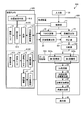
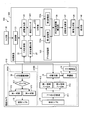
- FIG. 1 is a schematic view showing the configuration of the measurement apparatus according to the first embodiment.
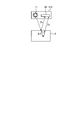
- FIG. 2 is a diagram showing how a measurement object is measured by the measurement device shown in FIG.
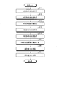
- FIG. 3 is a flowchart showing an operation of measuring a measurement object by the measuring device shown in FIG.
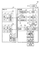
- FIG. 4 is a schematic view showing a configuration of a measurement apparatus according to a modification 1-1 of the first embodiment.
- FIG. 5 is a diagram showing how a measurement object is measured by the measurement device shown in FIG.
- FIG. 6 is a diagram for explaining the measurement method of the measurement apparatus shown in FIG.
- FIG. 7 is a diagram showing how a measurement object is measured by the measurement apparatus according to the modification 1-2 of the first embodiment.
- FIG. 1 is a schematic view showing the configuration of the measurement apparatus according to the first embodiment.
- FIG. 2 is a diagram showing how a measurement object is measured by the measurement device shown in FIG.
- FIG. 3 is a flowchart showing an operation of measuring a measurement object by the
- FIG. 8 is a schematic view showing a configuration of a measurement apparatus according to Modification 1-3 of Embodiment 1.
- FIG. 9 is a diagram showing how a measurement object is measured by the measurement device shown in FIG.
- FIG. 10 is a schematic view showing a configuration of a measurement apparatus according to Modification 1-4 of Embodiment 1.
- FIG. 11 is a diagram showing how a measurement object is measured by the measurement device shown in FIG.
- FIG. 12 is a schematic view showing a configuration of a measuring apparatus according to a modification 1-5 of the first embodiment.
- FIG. 13 is a diagram showing how a measurement object is measured by the measurement device shown in FIG.
- FIG. 14 shows how the position changing means shown in FIG. 12 moves the pattern filter.
- FIG. 14 shows how the position changing means shown in FIG. 12 moves the pattern filter.
- FIG. 15 is a diagram for explaining the measurement method of the measurement device shown in FIG.
- FIG. 16 is a diagram showing a modification of the pattern filter.
- FIG. 17 is a diagram showing a modification of the pattern filter.
- FIG. 18 is a diagram showing a pattern filter and a polarizing element of the measurement apparatus according to the modified example 1-6 of the first embodiment.
- FIG. 19 is a diagram showing how a measurement object is measured by the measurement device according to the modified example 1-6 of the first embodiment.
- FIG. 20 is a diagram for explaining a measurement method of the measurement apparatus according to the modified example 1-6 of the first embodiment.
- FIG. 21 is a schematic view showing a configuration of a measurement device according to a modified example 1-7 of the first embodiment.
- FIG. 22 is a schematic view showing a configuration of a measurement device according to Embodiment 2.
- FIG. 23 is a diagram showing how a measurement object is measured by the measurement device shown in FIG.
- FIG. 24 is a flowchart showing an operation of measuring a measurement object by the measurement device shown in FIG.
- FIG. 25 is a schematic view showing a configuration of a measuring device according to a modified example 2-1 of the second embodiment.
- FIG. 26 is a diagram illustrating how a measurement object is measured by the measurement device of Modification 2-2 of the second embodiment.
- FIG. 27 is a schematic view showing a configuration of a measurement device according to Embodiment 3.
- FIG. 28 is a schematic view showing a configuration of a measurement device according to Embodiment 4.
- FIG. 29 is a diagram showing how a measurement object is measured by the measurement device shown in FIG.
- FIG. 30 is a diagram showing how a measurement object is measured by the measurement device shown in FIG.
- FIG. 31 is a diagram showing how a measurement object is measured by the measurement device according to the modified example 4-1 of the fourth embodiment.
- FIG. 32 is a schematic configuration diagram of the measurement apparatus in the case where the illumination lens is a condensing lens.
- FIG. 33 is a schematic configuration diagram of a measurement apparatus provided with a light guide instead of the illumination lens.
- FIG. 1 is a schematic view showing the configuration of the measurement apparatus according to the first embodiment.
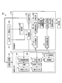
- the measurement apparatus 1 according to the first embodiment emits light to a measurement object and simultaneously receives a depth camera 10 that receives backscattered light in the measurement object and a signal acquired by the depth camera 10.
- Distance fixing mechanism for fixing the distance between the depth camera 10 and the measurement object, the processing unit 20 to process, the input unit 30 for receiving various inputs from the user, the display unit 40 for displaying the image generated by the processing unit 20 And 50.
- FIG. 2 is a diagram showing how a measurement object is measured by the measurement device shown in FIG.
- the depth camera 10 is disposed with respect to the measurement object 2 via an air layer.
- a reference distance Zo which is a distance between the surface of the measurement object 2 and the depth camera 10 is fixed by the distance fixing mechanism 50.
- the flight distance Zs is half of the distance traveled until the light projected from the depth camera 10 is backscattered inside the measuring object 2 and is incident on the depth camera 10.
- FIG. 2 although the light emitted from the light source 11 and the light incident on the light detector 16 are described at an angle, there are a plurality of such paths for explaining the light flight path. It is an excerpt of one of the illumination light paths.
- the light source 11 and the light axis of the light projected from the light source 11 and the light axis of the light incident on the light detector 16 are actually arranged at an angle to the measurement object 2.
- the light detector 16 may be arranged, the light source 11 and the light detector 16 may be arranged to be coaxial with the measurement object 2.
- the depth camera 10 includes a light source unit 10A that emits light whose light intensity is periodically modulated to the measurement object 2, and a light receiving unit 10B that receives backscattered light in the measurement object 2 of the projected light. Have.
- the light source unit 10A includes a light source 11 for projecting light onto the measurement object 2, a light source drive device 12 for driving and controlling the light source 11, and an illumination lens for irradiating the light projected by the light source 11 into a predetermined range of the measurement object 2. And 13.
- the light source 11 is, for example, an LED (Light Emitting Diode), and projects light having a wavelength of 850 nm.
- the light source 11 emits light whose light intensity is modulated so as to be a 30 MHz sine wave according to control by the light source drive device 12.
- intensity modulation of light projected from the light source 11 may be a pulse or a rectangular wave.
- the wavelength of light projected from the light source 11 is not particularly limited, and may be variable or may be light with a wide wavelength band.
- the illumination lens 13 is, for example, a high NA (e.g., both-side opening angle 90 °) diffusion lens that diffuses the light emitted from the light source 11.
- a high NA e.g., both-side opening angle 90 °
- the light receiving unit 10B includes a light receiving lens 14 for collecting backward scattered light in the measurement object 2, a wavelength filter 15 for transmitting only light of a predetermined wavelength, and a light detector 16 for detecting light transmitted through the wavelength filter 15.
- An amplifier 17 that amplifies the signal output from the light detector 16 and an AD conversion unit 18 that AD-converts the signal amplified by the amplifier 17 are provided.
- the light receiving lens 14 is, for example, a high NA (e.g., both-side opening angle 90 °) condensing lens that condenses the backscattered light in the measurement object 2.
- a high NA e.g., both-side opening angle 90 °
- the wavelength filter 15 is, for example, a band pass filter that selectively transmits only light in the vicinity of a wavelength of 850 nm.
- the wavelength filter 15 transmits only backscattered light in the measurement object 2 and prevents stray light of other wavelengths from entering the light detector 16.
- the photodetector 16 is a TOF sensor chip of a complementary metal oxide semiconductor (CMOS) type.
- CMOS complementary metal oxide semiconductor
- the photodetector 16 converts the received light into an electrical signal by photoelectric conversion.
- the light detector 16 may be a TOF sensor chip of a CCD (Charge Coupled Devices) type.
- the amplifier 17 amplifies and outputs the electrical signal output from the light detector 16.
- the AD conversion unit 18 converts (AD conversion) an electrical signal that is an analog signal amplified by the amplifier 17 into a digital signal and outputs the digital signal.
- the processing device 20 includes a control unit 21, a TOF measurement unit 22, a distance calculation unit 23, a Zo acquisition unit 24, a light intensity calculation unit 25, an internal propagation distance calculation unit 26, and an inverse analysis calculation as a calculation unit. And an image generation unit 28.
- the control unit 21 is realized by using a CPU (Central Processing Unit) or the like.
- the control unit 21 controls the processing operation of each unit of the processing device 20.
- the control unit 21 controls the operation of the processing device 20 by transferring instruction information and data to each component of the processing device 20. Further, the control unit 21 performs control such that the operations of the light source 11 and the light detector 16 are synchronized.
- the TOF measurement unit 22 measures, as TOF information, a phase shift of intensity modulation between the light emitted from the light source 11 and the light received by the light detector 16. Specifically, the phase of the light emitted by the light source unit 10A is acquired from the control unit 21, the phase of the light received by the light receiving unit 10B is acquired from the AD conversion unit 18, and the acquired phases are compared to obtain a phase shift. Calculate ⁇ .
- the distance calculation unit 23 propagates the light emitted from the light source unit 10A from the phase shift ⁇ calculated by the TOF measurement unit 22 until it reaches the light receiving unit 10B (see FIG. 2).
- Calculating the flight distance Zs of The flight distance Zs can be calculated as in the following equation (1) using the phase shift ⁇ , where fm is the frequency of intensity modulation and c is the velocity of light.
- the Zo acquiring unit 24 acquires the distance from the surface of the measurement object 2 to the light source unit 10A and the light receiving unit 10B (reference distance Zo in FIG. 2). Specifically, since the distance from the surface of the measurement object 2 to the light source unit 10A and the light receiving unit 10B is fixed to the reference distance Zo by the distance fixing mechanism 50, the reference distance Zo is acquired from the control unit 21.
- the Zo acquisition unit 24 may acquire the reference distance Zo by various methods capable of measuring the distance without contact, such as an AF function (contrast AF, image plane phase difference AF) of a digital camera.
- the light intensity calculator 25 calculates the light intensity from the electrical signal acquired from the AD converter 18.
- the light intensity A received by the light detector 16 is represented by the following equation (2) as the luminance value of each pixel of the TOF sensor chip at phases 0 °, 90 °, 180 °, and 270 ° for A0, A1, A2 and A3, respectively. It can be calculated as
- the internal propagation distance calculation unit 26 calculates an internal propagation distance ⁇ Z in the measurement object 2 according to the reference distance Zo acquired by the Zo acquisition unit 24 and the flight distance Zs calculated by the distance calculation unit 23. Specifically, the internal propagation distance ⁇ Z can be calculated as the following equation (3).
- the inverse analysis calculation unit 27 performs the inverse analysis on the scattering coefficient and the absorption coefficient of the measurement object 2 according to the internal propagation distance ⁇ Z calculated by the internal propagation distance calculation unit 26 and the light intensity A calculated by the light intensity calculation unit 25. Or calculate optical characteristics such as non-isotropic parameters.
- the image generation unit 28 generates and outputs an image signal based on the optical characteristic obtained by the inverse analysis operation unit 27 by calculation. Specifically, the image generation unit 28 generates an image signal in which the gradation, the color, the contrast, and the like are changed according to the value of the optical characteristic for each pixel obtained by the inverse analysis calculation unit 27 by the calculation.
- the image generation unit 28 may generate an image signal in which an image in which a color or the like is changed according to the value of the optical characteristic is superimposed on a 2D or 3D image or an ultrasonic image or the like captured by various cameras.
- the input unit 30 is realized using operation devices such as a mouse, a keyboard, and a touch panel, and receives an input of various instruction information of the measuring device 1.
- the display unit 40 is configured using a display or the like using liquid crystal or organic EL (Electro Luminescence).
- the display unit 40 displays an image based on the image signal output by the image generation unit 28.
- the distance fixing mechanism 50 has an abutting portion 51 that abuts on the measurement object 2 and an arm 52 that fixes the distance between the measurement object 2 and the depth camera 10 to a predetermined value.
- the space between the depth camera 10 and the contact portion 51 is, for example, an air layer, but may be a gas layer filled with another gas, or may be a vacuum layer.
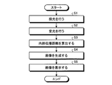
- FIG. 3 is a flowchart showing an operation of measuring a measurement object by the measuring device shown in FIG. As shown in FIG. 3, first, the light source driving device 12 performs light projection from the light source 11 to the measurement object 2 via the illumination lens 13 according to the control by the control unit 21 (step S1).
- the light detector 16 is synchronously controlled by the control unit 21 to receive light that has been backscattered in the measurement object 2 and has passed through the light receiving lens 14 and the wavelength filter 15 (step S2).
- the light detector 16 converts the received light signal into an electrical signal. Further, this electrical signal is amplified by the amplifier 17, AD converted by the AD converter 18, and output to the processing device 20.
- the internal propagation distance calculation unit 26 calculates the internal propagation distance ⁇ Z according to the output of the depth camera 10 (step S3). Specifically, the TOF measurement unit 22 calculates the phase shift ⁇ of intensity modulation between the light emitted from the light source 11 and the light received by the light detector 16, and the distance calculation unit 23 flies according to the phase shift ⁇ . Calculate the distance Zs. Further, the Zo acquisition unit 24 acquires the reference distance Zo from the control unit 21. Then, the internal propagation distance calculation unit 26 calculates the difference between the flight distance Zs and the reference distance Zo, and calculates the internal propagation distance ⁇ Z.
- the inverse analysis calculation unit 27 calculates the optical characteristics of the measurement object 2, and the image generation unit 28 generates an image according to the optical characteristics (step S4). Specifically, according to the internal propagation distance ⁇ Z calculated by the internal propagation distance calculation unit 26 by the inverse analysis operation unit 27 and the light intensity A calculated by the light intensity calculation unit 25, the optical characteristics of the measurement object 2 are obtained by inverse analysis. Calculate The image generation unit 28 generates and outputs an image signal according to the optical characteristic calculated by the inverse analysis calculation unit 27.
- the display unit 40 displays an image according to the image signal output from the image generation unit 28 (step S5).
- the light source unit 10A and the light receiving unit 10B are disposed on the measurement object 2 via the air layer, and are not in direct contact with each other. Further, as the distance acquisition unit, the distance fixing mechanism 50 fixes the distance between the light source unit 10A and the light receiving unit 10B and the measurement object 2 to the reference distance Zo, and the Zo acquisition unit 24 as the reference distance acquisition unit In order to obtain Zo, the internal propagation distance ⁇ Z can be calculated to calculate the optical characteristics inside the measurement object 2.
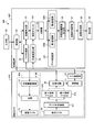
- FIG. 4 is a schematic view showing a configuration of a measurement apparatus according to a modification 1-1 of the first embodiment.
- the processing device 120 of the measuring device 100 according to the modification 1-1 determines the determination unit 121 that determines whether the light intensity calculated by the light intensity calculation unit 25 is a predetermined threshold or more, and the determination result of the determination unit 121.
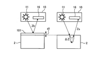
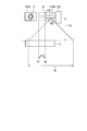
- FIG. 5 is a diagram showing how a measurement object is measured by the measurement device shown in FIG. As shown in FIG. 5, in the measuring apparatus 100, the distance Zb to the surface of the reference member 101 of thickness d1 made of a member having a high reflectance with respect to the wavelength band of light projected from the light source 11 Is determined by measurement.
- FIG. 6 is a diagram for explaining the measurement method of the measurement apparatus shown in FIG.
- the reference member 101 is arranged on the surface of the measurement object 2 so as to surround the periphery of the range to be measured using the depth camera 10 It is done.
- the horizontal axis (X axis) in FIG. 6 corresponds to the horizontal coordinate in FIG. 5, and the vertical axis (Z axis) in FIG. 6 corresponds to the vertical coordinate in FIG.
- the arrangement of the reference member 101 is not particularly limited.
- the reference members 101 may be disposed at four corners, or may be disposed as point markers.
- the determiner 121 determines whether the distance calculated by the distance calculation unit 23 is equal to or greater than a predetermined threshold. As shown in FIG. 6, the distances calculated on the broken line B are the distance Zb and the flight distance Zs. Therefore, when the distance calculated by the distance calculation unit 23 is smaller than the threshold T, the determiner 121 determines that the pixel is the pixel on which the reference member 101 is disposed and the light has traveled by the distance Zb. On the other hand, when the distance calculated by the distance calculation unit 23 is equal to or larger than the threshold T, the determiner 121 determines that the pixel is a pixel where the reference member 101 is not disposed and the light has traveled by the flight distance Zs. .
- the distributor 122 distributes the distance calculated by the distance calculation unit 23 and the light intensity calculated by the light intensity calculation unit 25 according to the determination result of the determination unit 121. Specifically, the distance and the light intensity of the pixel determined that the light has traveled by the distance Zb by the determiner 121, and the distance and the light intensity of the pixel determined that the light has traveled by the flight distance Zs by the determiner 121 And are distributed and stored in the data storage unit 123.
- the data storage unit 123 includes a first storage unit 123a and a second storage unit 123b.
- the distributor 122 stores the distance and light intensity of the pixel where the light has traveled by the distance Zb.
- the distributor 122 stores the distance and light intensity of the pixel at which the light has traveled by the flight distance Zs.
- the light source unit 10A and the light receiving unit 10B are disposed with respect to the measurement object 2 via the air layer, and are not in direct contact with each other.
- the reference member 101 is disposed as a distance acquiring unit, and the distance from the surface of the measurement object 2 to the light source unit 10A and the light receiving unit 10B is measured by measuring the distance to the reference member 101. Get each one.
- the internal propagation distance ⁇ Z can be calculated, and the optical characteristic of the inside of the measurement object 2 can be calculated.
- the reference member 101 is disposed in part of the area to be measured using the depth camera 10, and the distance Zb and the flight distance Zs are measured in one measurement, but the invention is not limited thereto.
- the reference member 101 may be disposed to cover the surface of the measurement object 2 to measure the distance Zb, and then the reference member 101 may be removed to measure the flight distance Zs.
- the inside of the measurement object 2 can be measured in the entire range measured by the depth camera 10.
- FIG. 7 is a diagram showing how a measurement object is measured by the measurement apparatus according to the modification 1-2 of the first embodiment.
- the distance Zb to the surface of the reference member 101 of thickness d1 and the flight distance Zs are determined by measurement.
- the reference member 101 is disposed on the surface of the transparent member 102.
- the reference member 101 is disposed in part of the area measured by the depth camera 10 as in the modification 1-1.
- a matching agent such as a liquid having a high transmittance is inserted. Is preferred.
- the internal propagation distance calculation unit 26 calculates an internal propagation distance ⁇ Z in the measurement object 2 according to the distance Zb and the flight distance Zs.
- the reference member 101 may be disposed on the transparent member 102. Also in this case, as in the modification 1-1, the reference member 101 is disposed so as to cover the surface of the measurement object 2 to measure the distance Zb, and then the reference member 101 is removed to measure the flight distance Zs. May be
- FIG. 8 is a schematic view showing a configuration of a measurement apparatus according to Modification 1-3 of Embodiment 1.
- the processing device 220 of the measuring device 200 according to the modification 1-3 calculates the reference distance Zo, which is the distance between the measuring object 2 and the depth camera 10, and the position commander 221 that controls the positioning mechanism 250.
- a Zo calculating unit 222 as a unit.
- FIG. 9 is a diagram showing how a measurement object is measured by the measurement device shown in FIG.
- the positioning mechanism 250 of the measuring device 200 is a movable member for moving the contact member 251 of the length La applied to the surface of the measurement object 2 and the contact member 251 and the depth camera 10 up and down. And 252.
- the positioning mechanism 250 applies the tip of the application member 251 to the surface of the measurement object 2 under the control of the position command unit 221. Then, from there, the movable portion 252 is returned by the distance Zm, and measurement is performed in this state.
- the light source unit 10A and the light receiving unit 10B are disposed with respect to the measurement object 2 via the air layer, and are not in direct contact with each other. Further, in the modification 1-3, since the reference distance Zo can be calculated by the positioning mechanism 250, the position command unit 221, and the Zo calculating unit 222 as the reference distance calculating unit as the distance acquiring unit, the internal propagation distance ⁇ Z Can be calculated, and optical characteristics inside the measurement object 2 can be calculated.
- the positioning mechanism 250 may be configured to extend and contract the contact member 251 to change only the length of the contact member 251.
- FIG. 10 is a schematic view showing a configuration of a measurement apparatus according to Modification 1-4 of Embodiment 1.
- FIG. 11 is a diagram showing how a measurement object is measured by the measurement device shown in FIG.
- the measuring device 300 according to the modification 1-4 has a configuration in which the contact sensor 360 is disposed at the tip of the application member 251 of the modification 1-3.
- the processing device 320 of the measuring device 300 includes a determination unit 321 that determines whether the contact sensor 360 has detected a contact.
- the contact sensor 360 can accurately detect whether the tip of the application member 251 contacts the surface of the measurement object 2. Therefore, it is prevented that an error occurs in the reference distance Zo calculated by the Zo calculating unit 222 by the elastic measuring object 2 being dented by the contact member 251.
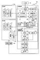
- FIG. 12 is a schematic view showing a configuration of a measuring apparatus according to a modification 1-5 of the first embodiment.
- the light source unit 810A includes the light source 11 projecting light onto the measurement object, and the light projected onto the measurement object from the light source 11
- a pattern filter 811 as an optical element that transmits light so as to form an illuminance distribution that periodically repeats a bright part and a dark part spatially, and an illuminance distribution change in which the position of the pattern filter 811 is moved to change the illuminance distribution
- position change means 812 as a means.
- the light receiving unit 810B has a polarizing element 813 for selectively transmitting light of a predetermined polarization.
- the processing device 820 of the measuring device 800 has a data storage unit 823 having n storage units (first storage unit 823a to n-th storage unit 823n).
- the light receiving unit 810B may not have the polarizing element 813.
- FIG. 13 is a diagram showing how a measurement object is measured by the measurement device shown in FIG.
- light projected from the light source 11 of the light source unit 810A is selectively transmitted by the pattern filter 811, and the tumor is formed as a fine stripe pattern in which the bright portion BS and the dark portion DS periodically repeat. , Etc. are projected onto a measuring object 2 having an observation object O.
- the pattern filter 811 is used to realize so-called structured illumination.
- the light detector 16 of the light receiving unit 810B receives the backward scattered light in the measurement object 2 of the projected light through the polarizing element 813. Further, the position changing unit 812 moves the pattern filter 811 in the direction orthogonal to the light projected from the light source 11.
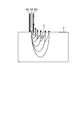
- FIG. 14 shows how the position changing means shown in FIG. 12 moves the pattern filter.
- the position changing means 812 moves the pattern filter 811
- the bright part BS and the dark part DS move.
- FIG. 14 shows only three dark parts DS among the plurality of dark parts DS shown in FIG.
- the position changing means 812 moves the pattern filter 811 n times at equal intervals. At this time, the light portion BS and the dark portion DS move by one pitch in total (until the light portion BS and the dark portion DS move to the positions of the light portion BS and the dark portion DS adjacent to each other).
- the light receiving unit 810B receives the backscattered light every time the pattern filter 811 is moved by the position changing unit 812 and acquires n measurement results.
- the n measurement results are stored in the first storage unit 823a to the n-th storage unit 823n, respectively.
- the Zo acquisition unit 24 calculates the reference distance Zo using the measurement results of the bright portion BS and the dark portion DS of the n backscattered lights stored in the first storage unit 823a to the n-th storage unit 823n.
- FIG. 15 is a diagram for explaining the measurement method of the measurement device shown in FIG. As shown in FIG. 15, the light received from the dark part DS does not include the direct reflection reflected on the surface of the measurement object 2 and the single scattering component scattered only once in the surface layer of the measurement object 2. Is the light that is multiply scattered inside. On the other hand, the light received from the bright portion BS is light including direct reflection, single scattering, and multiple scattering components. In FIG. 15, only two dark parts DS among the plurality of dark parts DS shown in FIG. 13 are shown.
- the phase of measurement results in the case of not structured illumination is ⁇ o (median value)
- the amplitude is ⁇ o (median value)
- the phase of direct components directly reflection and single scattering
- the amplitude is ⁇ d
- indirect components multiplex Assuming that the phase of scattering) is ⁇ g and the amplitude is ⁇ g
- the return light of the intensity modulated light projected from the light source 11 has the following equation (5) according to the correlation function c ( ⁇ ) using the phase delay ⁇ of the return light Is represented by
- fm is the frequency of intensity modulation
- ⁇ is the intensity (intermediate value).
- the measurement result of the bright part BS corresponds to the equations (6) and (7)
- four equations are obtained.
- the phase ⁇ d h (estimated value) of the direct component can be obtained.
- the reference distance Zo can be calculated by calculating the distance in the same manner as equation (1) using this phase ⁇ d h .
- the internal propagation distance calculation unit 26 calculates an internal propagation distance ⁇ Z using the n measurement results stored in the first storage unit 823a to the nth storage unit 823n. Specifically, the internal propagation distance calculation unit 26 calculates the internal propagation distance ⁇ Z using the measurement result of the dark part DS of the n backscattered lights received by the light receiving unit 810B. As described above, since the light received from the dark part DS is the light which is multiply scattered in the inside of the measurement object 2, the flight distance Zs is calculated from this measurement result, and the reference distance Zo calculated by the Zo acquisition unit 24 is used. Then, the internal propagation distance ⁇ Z is calculated by the equation (3).
- the reference distance Zo since the reference distance Zo is calculated using structured illumination, the reference distance Zo can be accurately calculated even if the surface of the measurement object 2 has unevenness.
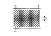
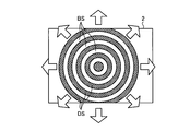
- FIG. 16 and FIG. 17 are diagrams showing modified examples of the pattern filter.
- the pattern filter 811 may have a checkered pattern in which the bright parts BS and the dark parts DS are arranged in a fine grid.
- the position changing unit 812 moves the pattern filter 811 in the left and right direction or in the up and down direction.
- the pattern filter 811 may be configured to have a pattern in which the bright portions BS and the dark portions DS are arranged in fine concentric circles. In this case, the position changing means 812 moves the pattern filter 811 away from or close to the light source 11. Then, the concentric stripes move radially outward or inward.
- the present invention is not limited thereto.
- the light receiving unit 810B projects the structured illumination onto a part of the measurement object 2 and projects the intensity modulated light onto the region of the measurement object 2 to be observed to obtain backscattered light once.
- the position changing unit 812 moves the position of the pattern filter 811 as the illuminance distribution changing unit has been described, but the present invention is not limited thereto.
- the position changing means as the illuminance distribution changing means may move the position of the light source 11.
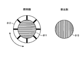
- FIG. 18 is a diagram showing a pattern filter and a polarizing element of the measurement apparatus according to the modified example 1-6 of the first embodiment.
- the depth camera 810 of the measuring device 800 according to the modification 1-6 changes the position of rotating the pattern filter 811 and the disk-shaped pattern filter 811 disposed on the illumination side (light source unit 810A).
- a disk-like polarizing element 813 disposed on the light receiving side (light receiving unit 810B).
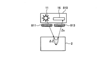
- FIG. 19 and FIG. 20 are diagrams for explaining the measurement method of the measurement apparatus according to the modified example 1-6 of the first embodiment.
- light projected from the light source 11 of the depth camera 810 is selectively transmitted by the pattern filter 811, and the tumor is formed as a fine stripe pattern in which the bright part BS and the dark part DS periodically repeat.
- Etc. are projected onto a measuring object 2 having an observation object O.
- the light detector 16 of the light receiving unit 810B of the depth camera 810 receives the backward scattered light in the measurement object 2 of the projected light through the polarizing element 813.
- the position changing means 812 rotates the pattern filter 811 n times at the same angle as shown in FIGS.
- the position changing unit 812 rotationally moves the pattern filter 811 until the light portion BS and the dark portion DS move to the positions of the light portion BS and the dark portion DS adjacent to each other.
- the light receiving unit 810B receives the backscattered light every time the pattern filter 811 is rotationally moved by the position changing unit 812 and acquires n measurement results.
- the n measurement results are stored in the first storage unit 823a to the n-th storage unit 823n, respectively.
- the internal propagation distance calculation unit 26 calculates the internal propagation distance ⁇ Z using the measurement results stored in the first storage unit 823a to the nth storage unit 823n, as in the first to fifth modifications.
- FIG. 21 is a schematic view showing a configuration of a measurement device according to a modified example 1-7 of the first embodiment.
- the light source 910A is replaced by the pattern filter 811 of the modification 1-5 shown in FIG.
- An element 911 is disposed.
- direct components direct reflection and single scattering
- indirect components multiple scattering
- the reference distance Zo is obtained.
- the polarizing element 911 and the polarizing element 813 in orthogonal Nicols, only the indirect component (multiple scattering) can be measured, and the internal propagation distance ⁇ Z can be calculated from the measurement result.
- FIG. 22 is a schematic view showing a configuration of a measurement device according to Embodiment 2. The description of the same configuration as that of the measuring device 1 of the first embodiment will be omitted as appropriate.
- the light receiving unit 410B of the depth camera 410 of the measuring device 400 transmits the filter switching unit 411 that switches the filter, the first wavelength filter 412 that transmits only the light of the first wavelength band, and the light of the second wavelength band. And a second wavelength filter 413.
- the light source 11 is, for example, a xenon lamp that projects light of a broad spectrum of wavelength 180 nm to 2000 nm.
- a wavelength filter is disposed between the light source 11 and the illumination lens 13 so that light in the ultraviolet range harmful to the living body is not projected to the measurement object 2, or illumination It is preferable to provide the lens 13 with a coating that does not transmit a predetermined wavelength band.
- the filter switching unit 411 switches the first wavelength filter 412 and the second wavelength filter 413, for example, according to the user's input.
- measurement is performed at least twice, but in the first measurement, the first wavelength filter 412 is disposed on the optical path of the backscattered light in the measurement object 2, and the second measurement is performed Then, the second wavelength filter 413 is disposed on the optical path of the backscattered light in the measurement object 2.
- the first wavelength filter 412 is, for example, a band pass filter that transmits only a near ultraviolet wavelength band.
- the second wavelength filter 413 is, for example, a band pass filter that transmits only light near a wavelength of 540 nm.
- FIG. 23 is a diagram showing how a measurement object is measured by the measurement device shown in FIG.
- the light in the near ultraviolet region transmitted by the first wavelength filter 412 is light backscattered in the very surface layer of the measurement object 2, and the flight distance of this light approximates the reference distance Zo. Can.
- the light of wavelength 540 nm transmitted by the second wavelength filter 413 is light of the flight distance Zs backscattered after the internal propagation of the measurement object 2.
- the processing device 420 of the measuring device 400 has a measurement counter 421 that counts the number of measurements.
- the distributor 122 stores the first measured data in the first storage unit 123a according to the count of the measurement counter 421, and stores the second measured data in the second storage unit 123b.
- FIG. 24 is a flowchart showing an operation of measuring a measurement object by the measurement device shown in FIG. As shown in FIG. 24, first, the light source driving device 12 performs the first light projection on the measurement object 2 from the light source 11 through the illumination lens 13 according to the control by the control unit 21 (step S11).
- the light detector 16 performs the first light reception (step S12).
- the first wavelength filter 412 is disposed on the optical path of the light backscattered in the measurement object 2 by the filter switching unit 411. Therefore, the light detector 16 receives light that has been backscattered in the measurement object 2 and has passed through the light receiving lens 14 and the first wavelength filter 412.
- the light detector 16 converts the received light signal into an electrical signal. Further, this electrical signal is amplified by the amplifier 17, AD converted by the AD converter 18, and output to the processing device 420. This signal is distributed to the distributor 122 in the processing unit 420 and stored in the first storage unit 123a.
- the filter switching unit 411 switches the filter disposed on the optical path of the light backscattered in the measurement object 2 from the first wavelength filter 412 to the second wavelength filter 413 (step S13).
- the light source driving device 12 performs the second light projection on the measurement object 2 from the light source 11 through the illumination lens 13 under the control of the control unit 21 (step S14).
- the light detector 16 performs the second light reception (step S15).
- the second wavelength filter 413 is disposed on the optical path of the light backscattered in the measurement object 2 by the filter switching unit 411. Accordingly, the light detector 16 receives light that has been backscattered in the measurement object 2 and has passed through the light receiving lens 14 and the second wavelength filter 413.
- the light detector 16 converts the received light signal into an electrical signal. Further, this electrical signal is amplified by the amplifier 17, AD converted by the AD converter 18, and output to the processing device 20. This signal is distributed to the distributor 122 in the processor 20 and stored in the second storage unit 123b.
- the internal propagation distance calculation unit 26 calculates the internal propagation distance ⁇ Z according to the output of the depth camera 410 (step S3). Specifically, the internal propagation distance calculation unit 26 calculates the reference distance Zo from the signal obtained in the first measurement, and calculates the difference between the signal obtained in the second measurement and the flight distance Zs, The internal propagation distance ⁇ Z is calculated.
- the light source unit 10A and the light receiving unit 410B are disposed on the measurement object 2 via the air layer, and are not in direct contact with each other.
- the distance acquisition unit includes the filter switching unit 411, the first wavelength filter 412, and the second wavelength filter 413, and changes the wavelength of the light received by the light receiving unit 410B to perform measurement. Since Zo can be determined, the internal propagation distance ⁇ Z can be calculated to calculate the optical characteristics inside the measurement object 2.
- the depth of the measurement object 2 can be measured by setting the wavelength of light transmitted through the second wavelength filter 413 to a longer wavelength. Therefore, by adjusting the wavelength of the light transmitted through the second wavelength filter 413, it is possible for the user to measure the desired depth.
- FIG. 25 is a schematic view showing a configuration of a measuring device according to a modified example 2-1 of the second embodiment.
- the light source unit 510A of the depth camera 510 of the measuring apparatus 500 includes a switch 511 for switching the light source to be driven, a first light source 512 for projecting light of the first wavelength, and a second wavelength. And a second light source 513 for projecting light.
- the measurement apparatus 500 can perform the same measurement as that of the second embodiment by changing the wavelength of light emitted from the light source unit 510A.
- the light receiving unit 410 ⁇ / b> B may not include the filter switching unit 411, the first wavelength filter 412, and the second wavelength filter 413.
- FIG. 26 is a diagram illustrating how a measurement object is measured by the measurement device of Modification 2-2 of the second embodiment.
- a reference member 101a is disposed on the surface of the measurement object 2 to reflect light in the ultraviolet region and transmit light having a wavelength of 540 nm.
- the position where the reference member 101a is disposed may be the same as that of the modification 1-1 of the first embodiment.
- the reference distance Zo is calculated from the light in the ultraviolet region, and the optical characteristic of the inside of the measurement object 2 is calculated by the light of wavelength 540 nm. Therefore, as in the modification 1-1 of the first embodiment, the optical characteristics inside the measuring object 2 can be measured by one measurement.
- the reference member 101a may be disposed to cover the surface of the measurement object 2 to measure the reference distance Zo, and then the reference member 101a may be removed to measure the flight distance Zs.
- FIG. 27 is a schematic view showing a configuration of a measurement device according to Embodiment 3.
- the processing device 620 of the measuring device 600 has a frequency switching unit 621 that switches the frequency of intensity modulation of light emitted by the light source 11.
- the frequency switching unit 621 switches the frequency of intensity modulation to, for example, 30 MHz and 3 GHz.
- the phase shift in the case of measurement at a modulation frequency of 30 MHz is ⁇ 1
- the phase shift in the case of measurement at a modulation frequency of 3 GHz is ⁇ 2
- the distance calculated from the phase shift ⁇ 1 can be approximately regarded as the reference distance Zo.
- the internal propagation distance ⁇ Z can be calculated from these differences.
- the light source unit 10A and the light receiving unit 10B are disposed with respect to the measurement object 2 via the air layer, and are not in direct contact with each other. Further, as the distance acquisition unit, the frequency switching unit 621 changes the frequency of intensity modulation of light projected by the light source unit 10A to measure the reference distance Zo, so the internal propagation distance ⁇ Z is calculated. Thus, the optical characteristics of the inside of the measurement object 2 can be calculated.
- FIG. 28 is a schematic view showing a configuration of a measurement device according to Embodiment 4. As shown in FIG. 28, in the measuring apparatus 700, the light source unit 710A and the light receiving unit 710B are divided, and the light receiving unit 710B is configured to be movable by the positioning mechanism 750 as a moving unit. .
- the internal propagation distance calculation unit 721 calculates a Zo that calculates a reference distance Zo, a determination unit 721a that determines a pixel indicating a predetermined abnormal value, a correction unit 721b that corrects measurement data, and A section 721 c and a propagation calculation section 721 d that calculates an internal propagation distance ⁇ Z.
- FIG. 29 and FIG. 30 are views showing how a measuring object is measured by the measuring device shown in FIG.
- the light receiving unit 710B is disposed at the position X1 to perform the first measurement, and the light receiving unit 710B is moved by the movement amount ⁇ X by the positioning mechanism 750 and disposed at the position X2.
- the first storage unit 123a of the data storage unit 123 stores first measurement data
- the second storage unit 123b stores second measurement data
- the determination unit 721a determines pixels each indicating a predetermined abnormal value from the first measurement data and the second measurement data stored in the data storage unit 123. As shown in FIG. 30, when the measurement is performed using the measuring device 700, the pixel S corresponding to a specific position of the light receiving unit 710B may show the flight distance Zs and the light intensity A which are significantly different from the peripheral pixels. . The determination unit 721a determines a pixel S indicating this abnormal value.
- the correction unit 721b corrects the flight distance Zs and the light intensity A of the pixel S indicating the abnormal value using the flight distance Zs and the light intensity A of the peripheral pixels.
- the Zo calculating unit 721c calculates a reference distance Zo from the movement of the pixel S indicating an abnormal value.
- the position of the pixel S on the measurement object 2 does not change even if the light receiving unit 710B is moved.
- the pixel S indicating the abnormal value moves by the number of pixels ⁇ GN in the light receiving unit 710B.
- m be the total number of pixels arranged in the movement direction. Since it is possible to approximate ⁇ X / W, which is the ratio of the moved distance, and ⁇ GN / m, which is the ratio of the moved pixel, the following equation (9) holds.
- the Zo calculating unit 721c acquires the movement amount ⁇ X from the position command unit 221, acquires the number of pixels ⁇ GN from the measurement data, and substitutes it into Expression (10) to calculate the reference distance Zo.
- the propagation calculating unit 721d calculates the internal propagation distance ⁇ Z using the corrected measurement data output from the correcting unit 721b and the reference distance Zo calculated by the Zo calculating unit 721c.
- the propagation calculation unit 721d may calculate the internal propagation distance ⁇ Z from either the first measurement data or the second measurement data, or the first measurement data and the second measurement data.
- the internal propagation distance ⁇ Z may be calculated from the average value.
- the light source unit 710A and the light receiving unit 710B are disposed on the measurement object 2 via the air layer, and are not in direct contact with each other.
- the reference distance Zo can be determined by performing measurement at positions before and after moving the light receiving unit 710B as a distance acquisition unit, the internal propagation distance ⁇ Z is calculated to calculate the optical characteristics inside the measurement object 2 can do.
- FIG. 31 is a diagram showing how a measurement object is measured by the measurement device according to the modified example 4-1 of the fourth embodiment. As shown in FIG. 31, in this measurement device, the reference distance Zo is calculated in the same manner as in the fourth embodiment by moving the light source unit 710A and performing measurement.
- the reference distance Zo is calculated by moving the light source unit 710A or the light receiving unit 710B in the horizontal direction in the fourth embodiment and the modification 4-1, the present invention is not limited to this.
- the reference distance Zo may be calculated by moving the light source unit 710A or the light receiving unit 710B in the vertical direction.
- a plurality of light source units 710A or light receiving units 710B may be disposed at different positions, and the reference distance Zo may be calculated by switching the light source units 710A or the light receiving units 710B that are sequentially operated.
- FIG. 32 is a schematic configuration diagram of the measurement apparatus in the case where the illumination lens is a condensing lens. As shown in FIG. 32, a condenser lens 13a may be used as the illumination lens.
- FIG. 33 is a schematic configuration diagram of a measurement apparatus provided with a light guide instead of the illumination lens. As shown in FIG. 33, instead of the illumination lens, a light guide 13b for guiding the light emitted from the light source 11 may be used.
- the light guide 13b may be a tube having a mirror surface inside, or may be an optical fiber.
- the TOF measurement unit 22 calculates a phase shift of intensity modulation between light projected from the light source 11 and light received by the light detector 16 as TOF information. It is not limited to this.
- the TOF measurement unit 22 projects the pulse light from the light source 11 as TOF information, and the time delay until the return light from the measurement object 2 is received Measure Then, the distance calculation unit 23 calculates the flight distance Zs from the time delay measured by the TOF measurement unit 22.
- Measuring device 2 Measuring object 10, 410, 510, 810, 910 Depth camera 10A, 510A, 710A, 810A, 910A
Landscapes
- Physics & Mathematics (AREA)
- Engineering & Computer Science (AREA)
- General Physics & Mathematics (AREA)
- Electromagnetism (AREA)
- Remote Sensing (AREA)
- Radar, Positioning & Navigation (AREA)
- Computer Networks & Wireless Communication (AREA)
- Biochemistry (AREA)
- Health & Medical Sciences (AREA)
- Pathology (AREA)
- General Health & Medical Sciences (AREA)
- Analytical Chemistry (AREA)
- Chemical & Material Sciences (AREA)
- Life Sciences & Earth Sciences (AREA)
- Immunology (AREA)
- Theoretical Computer Science (AREA)
- Spectroscopy & Molecular Physics (AREA)
- Mathematical Physics (AREA)
- Length Measuring Devices By Optical Means (AREA)
- Investigating Or Analysing Materials By Optical Means (AREA)
- Measurement Of Optical Distance (AREA)
Abstract
Le dispositif de mesure selon la présente invention comprend : une unité de source de lumière permettant de projeter une lumière pulsée ou une lumière périodiquement modulée en intensité sur un objet de mesure, l'unité de source de lumière étant placée avec une couche de gaz ou une couche de vide interposée entre l'objet de mesure et l'unité de source de lumière ; une unité de réception de lumière permettant de recevoir la lumière rétrodiffusée qui est rétrodiffusée par l'objet de mesure à partir de la lumière projetée par l'unité de source de lumière, l'unité de réception de lumière étant placée avec la couche de gaz ou la couche de vide interposée entre l'objet de mesure et l'unité de réception de lumière ; et une unité de mesure de temps de vol (TOF) permettant de mesurer des informations de TOF de la lumière rétrodiffusée reçue par l'unité de réception de lumière. Un dispositif de mesure est ainsi fourni, grâce auquel l'objet de mesure peut être mesuré à l'aide d'une estimation de TOF sans contact avec l'objet de mesure par l'unité de source de lumière ou l'unité de réception de lumière.
Priority Applications (2)
| Application Number | Priority Date | Filing Date | Title |
|---|---|---|---|
| JP2018508968A JPWO2017169732A1 (ja) | 2016-03-28 | 2017-03-14 | 計測装置及び計測方法 |
| US16/139,275 US11486703B2 (en) | 2016-03-28 | 2018-09-24 | Measuring apparatus and measuring method |
Applications Claiming Priority (2)
| Application Number | Priority Date | Filing Date | Title |
|---|---|---|---|
| JP2016064725 | 2016-03-28 | ||
| JP2016-064725 | 2016-03-28 |
Related Child Applications (1)
| Application Number | Title | Priority Date | Filing Date |
|---|---|---|---|
| US16/139,275 Continuation US11486703B2 (en) | 2016-03-28 | 2018-09-24 | Measuring apparatus and measuring method |
Publications (1)
| Publication Number | Publication Date |
|---|---|
| WO2017169732A1 true WO2017169732A1 (fr) | 2017-10-05 |
Family
ID=59964625
Family Applications (1)
| Application Number | Title | Priority Date | Filing Date |
|---|---|---|---|
| PCT/JP2017/010149 Ceased WO2017169732A1 (fr) | 2016-03-28 | 2017-03-14 | Dispositif de mesure et procédé de mesure |
Country Status (3)
| Country | Link |
|---|---|
| US (1) | US11486703B2 (fr) |
| JP (1) | JPWO2017169732A1 (fr) |
| WO (1) | WO2017169732A1 (fr) |
Cited By (2)
| Publication number | Priority date | Publication date | Assignee | Title |
|---|---|---|---|---|
| WO2024106458A1 (fr) * | 2022-11-18 | 2024-05-23 | 国立大学法人徳島大学 | Dispositif d'imagerie, dispositif d'inspection utilisant ledit dispositif d'imagerie et procédé d'imagerie |
| US20240198124A1 (en) * | 2021-08-17 | 2024-06-20 | Shimadzu Corporation | Phototherapy planning device and phototherapy planning method |
Families Citing this family (9)
| Publication number | Priority date | Publication date | Assignee | Title |
|---|---|---|---|---|
| US10791286B2 (en) | 2018-12-13 | 2020-09-29 | Facebook Technologies, Llc | Differentiated imaging using camera assembly with augmented pixels |
| US10791282B2 (en) | 2018-12-13 | 2020-09-29 | Fenwick & West LLP | High dynamic range camera assembly with augmented pixels |
| US10855896B1 (en) * | 2018-12-13 | 2020-12-01 | Facebook Technologies, Llc | Depth determination using time-of-flight and camera assembly with augmented pixels |
| US11223759B2 (en) * | 2019-02-19 | 2022-01-11 | Lite-On Electronics (Guangzhou) Limited | Exposure method and image sensing device using the same |
| US20220268942A1 (en) * | 2019-07-16 | 2022-08-25 | Sony Group Corporation | Light receiving device and method for driving light receiving device |
| US10902623B1 (en) | 2019-11-19 | 2021-01-26 | Facebook Technologies, Llc | Three-dimensional imaging with spatial and temporal coding for depth camera assembly |
| US11194160B1 (en) | 2020-01-21 | 2021-12-07 | Facebook Technologies, Llc | High frame rate reconstruction with N-tap camera sensor |
| JP7659884B2 (ja) * | 2021-01-28 | 2025-04-10 | 国立大学法人静岡大学 | 距離画像撮像装置及び距離画像を撮像する方法 |
| FR3154184B1 (fr) * | 2023-10-17 | 2025-11-07 | Commissariat A L’Energie Atomique Et Aux Energies Alternatives | Procédé et dispositif pour la spectroscopie par réflectance diffuse comprenant une modulation en intensité et/ou en fréquence optique du rayonnement optique. |
Citations (5)
| Publication number | Priority date | Publication date | Assignee | Title |
|---|---|---|---|---|
| JPH03501652A (ja) * | 1988-07-07 | 1991-04-11 | カマン アエロスペース コーポレイシヨン | Kファクターおよび深さの測定値を決定するための方法および装置 |
| JPH10111238A (ja) * | 1996-10-03 | 1998-04-28 | Technol Res Assoc Of Medical & Welfare Apparatus | 散乱体の吸収情報の計測方法及び装置 |
| JP2004333344A (ja) * | 2003-05-09 | 2004-11-25 | Hitachi Ltd | 光計測方法および装置 |
| JP2010210506A (ja) * | 2009-03-11 | 2010-09-24 | Nikon Corp | 測定装置及び測定方法 |
| JP2013190350A (ja) * | 2012-03-14 | 2013-09-26 | Canon Inc | テラヘルツ波帯の電磁波を用いた装置 |
Family Cites Families (14)
| Publication number | Priority date | Publication date | Assignee | Title |
|---|---|---|---|---|
| JPH0833355B2 (ja) * | 1987-10-16 | 1996-03-29 | トヨタ自動車株式会社 | 表面欠陥検査装置 |
| DE4445683A1 (de) | 1994-12-21 | 1996-06-27 | Boehringer Mannheim Gmbh | Verfahren zur Untersuchung eines streuenden Mediums mit intensitätsmoduliertem Licht |
| JP4018799B2 (ja) | 1998-04-02 | 2007-12-05 | 浜松ホトニクス株式会社 | 散乱吸収体の吸収成分の濃度計測方法及び装置 |
| JP2000292133A (ja) * | 1999-04-02 | 2000-10-20 | Nippon Steel Corp | パターン投影装置 |
| US7823782B2 (en) * | 2005-11-22 | 2010-11-02 | Shofu Inc. | Dental optical coherence tomograph |
| US8659039B2 (en) * | 2009-02-18 | 2014-02-25 | National Institute Of Advanced Industrial Science And Technology | Semiconductor light emitting diode |
| US9686532B2 (en) * | 2011-04-15 | 2017-06-20 | Faro Technologies, Inc. | System and method of acquiring three-dimensional coordinates using multiple coordinate measurement devices |
| EP2837321A4 (fr) * | 2012-04-10 | 2016-03-02 | Olympus Corp | Dispositif de mesure optique et système endoscopique |
| US9247874B2 (en) * | 2013-02-01 | 2016-02-02 | Carl Zeiss Meditec, Inc. | Systems and methods for sub-aperture based aberration measurement and correction in interferometric imaging |
| JP6444027B2 (ja) * | 2013-12-09 | 2018-12-26 | キヤノン株式会社 | 情報処理装置、情報処理装置の制御方法、情報処理システムおよびプログラム |
| WO2015087666A1 (fr) * | 2013-12-11 | 2015-06-18 | オリンパス株式会社 | Étalonneur et dispositif d'étalonnage |
| JP6362339B2 (ja) * | 2014-01-28 | 2018-07-25 | キヤノン株式会社 | 画像処理装置、画像処理方法およびプログラム |
| GB2534408B (en) * | 2015-01-23 | 2021-06-09 | Guidance Marine Ltd | Position reference sensor |
| CN106257915B (zh) * | 2015-06-17 | 2021-02-26 | 松下知识产权经营株式会社 | 摄像装置 |
-
2017
- 2017-03-14 WO PCT/JP2017/010149 patent/WO2017169732A1/fr not_active Ceased
- 2017-03-14 JP JP2018508968A patent/JPWO2017169732A1/ja active Pending
-
2018
- 2018-09-24 US US16/139,275 patent/US11486703B2/en active Active
Patent Citations (5)
| Publication number | Priority date | Publication date | Assignee | Title |
|---|---|---|---|---|
| JPH03501652A (ja) * | 1988-07-07 | 1991-04-11 | カマン アエロスペース コーポレイシヨン | Kファクターおよび深さの測定値を決定するための方法および装置 |
| JPH10111238A (ja) * | 1996-10-03 | 1998-04-28 | Technol Res Assoc Of Medical & Welfare Apparatus | 散乱体の吸収情報の計測方法及び装置 |
| JP2004333344A (ja) * | 2003-05-09 | 2004-11-25 | Hitachi Ltd | 光計測方法および装置 |
| JP2010210506A (ja) * | 2009-03-11 | 2010-09-24 | Nikon Corp | 測定装置及び測定方法 |
| JP2013190350A (ja) * | 2012-03-14 | 2013-09-26 | Canon Inc | テラヘルツ波帯の電磁波を用いた装置 |
Cited By (2)
| Publication number | Priority date | Publication date | Assignee | Title |
|---|---|---|---|---|
| US20240198124A1 (en) * | 2021-08-17 | 2024-06-20 | Shimadzu Corporation | Phototherapy planning device and phototherapy planning method |
| WO2024106458A1 (fr) * | 2022-11-18 | 2024-05-23 | 国立大学法人徳島大学 | Dispositif d'imagerie, dispositif d'inspection utilisant ledit dispositif d'imagerie et procédé d'imagerie |
Also Published As
| Publication number | Publication date |
|---|---|
| JPWO2017169732A1 (ja) | 2019-02-14 |
| US11486703B2 (en) | 2022-11-01 |
| US20190033070A1 (en) | 2019-01-31 |
Similar Documents
| Publication | Publication Date | Title |
|---|---|---|
| WO2017169732A1 (fr) | Dispositif de mesure et procédé de mesure | |
| US8810647B2 (en) | Time-of-flight based imaging system using a display as illumination source | |
| US9058081B2 (en) | Application using a single photon avalanche diode (SPAD) | |
| EP2594959B1 (fr) | Système et procédé pour le fonctionnement de caméra TOF multiple utilisant un saut de phase | |
| US9635351B2 (en) | Integrated reference pixel | |
| EP2823748B1 (fr) | Dispositif de mesure optique et procédé d'association d'un faisceau de fibres | |
| CN112034485B (zh) | 利用飞行时间相机的反射率感测 | |
| TWI442077B (zh) | 空間資訊偵測裝置 | |
| TWI897871B (zh) | 飛行時間感測系統及其中使用的圖像感測器 | |
| US9267790B2 (en) | Measuring device of measurement object, calculating device, measurement method, and method for producing item | |
| US9019576B2 (en) | Scanning apparatus with patterned probe light | |
| JP7270702B2 (ja) | 深度感知システムおよび方法 | |
| CN101322025A (zh) | 光图像测量装置 | |
| US11493331B2 (en) | Three-dimensional shape measuring apparatus, three-dimensional shape measuring method, three-dimensional shape measuring computer-readable storage medium, and three-dimensional shape measuring computer-readable storage device | |
| JP2014219404A (ja) | 数波長で同時に面の三次元測定を行う装置及び方法 | |
| US20200265608A1 (en) | Image Processing Apparatus | |
| US11209712B2 (en) | Image processing apparatus | |
| US12320897B2 (en) | High resolution time-of-flight measurements | |
| CN108174059B (zh) | 摄像装置 | |
| JP2012189479A (ja) | 形状計測装置 | |
| KR101802894B1 (ko) | Tof 및 구조광 방식이 융합된 3차원 영상 획득 시스템 | |
| KR102610830B1 (ko) | 거리 정보를 획득하는 방법 및 디바이스 | |
| JP5133614B2 (ja) | 3次元形状測定システム | |
| US20120133617A1 (en) | Application using a single photon avalanche diode (spad) | |
| JP2011021970A (ja) | 三次元形状測定装置および三次元形状測定方法 |
Legal Events
| Date | Code | Title | Description |
|---|---|---|---|
| WWE | Wipo information: entry into national phase |
Ref document number: 2018508968 Country of ref document: JP |
|
| NENP | Non-entry into the national phase |
Ref country code: DE |
|
| 121 | Ep: the epo has been informed by wipo that ep was designated in this application |
Ref document number: 17774276 Country of ref document: EP Kind code of ref document: A1 |
|
| 122 | Ep: pct application non-entry in european phase |
Ref document number: 17774276 Country of ref document: EP Kind code of ref document: A1 |