WO2017169976A1 - シール付軸受 - Google Patents
シール付軸受 Download PDFInfo
- Publication number
- WO2017169976A1 WO2017169976A1 PCT/JP2017/011204 JP2017011204W WO2017169976A1 WO 2017169976 A1 WO2017169976 A1 WO 2017169976A1 JP 2017011204 W JP2017011204 W JP 2017011204W WO 2017169976 A1 WO2017169976 A1 WO 2017169976A1
- Authority
- WO
- WIPO (PCT)
- Prior art keywords
- seal
- bearing
- lip
- ring
- groove wall
- Prior art date
- Legal status (The legal status is an assumption and is not a legal conclusion. Google has not performed a legal analysis and makes no representation as to the accuracy of the status listed.)
- Ceased
Links
Images



Classifications
-
- F—MECHANICAL ENGINEERING; LIGHTING; HEATING; WEAPONS; BLASTING
- F16—ENGINEERING ELEMENTS AND UNITS; GENERAL MEASURES FOR PRODUCING AND MAINTAINING EFFECTIVE FUNCTIONING OF MACHINES OR INSTALLATIONS; THERMAL INSULATION IN GENERAL
- F16C—SHAFTS; FLEXIBLE SHAFTS; ELEMENTS OR CRANKSHAFT MECHANISMS; ROTARY BODIES OTHER THAN GEARING ELEMENTS; BEARINGS
- F16C19/00—Bearings with rolling contact, for exclusively rotary movement
- F16C19/02—Bearings with rolling contact, for exclusively rotary movement with bearing balls essentially of the same size in one or more circular rows
- F16C19/04—Bearings with rolling contact, for exclusively rotary movement with bearing balls essentially of the same size in one or more circular rows for radial load mainly
- F16C19/06—Bearings with rolling contact, for exclusively rotary movement with bearing balls essentially of the same size in one or more circular rows for radial load mainly with a single row or balls
-
- F—MECHANICAL ENGINEERING; LIGHTING; HEATING; WEAPONS; BLASTING
- F16—ENGINEERING ELEMENTS AND UNITS; GENERAL MEASURES FOR PRODUCING AND MAINTAINING EFFECTIVE FUNCTIONING OF MACHINES OR INSTALLATIONS; THERMAL INSULATION IN GENERAL
- F16C—SHAFTS; FLEXIBLE SHAFTS; ELEMENTS OR CRANKSHAFT MECHANISMS; ROTARY BODIES OTHER THAN GEARING ELEMENTS; BEARINGS
- F16C33/00—Parts of bearings; Special methods for making bearings or parts thereof
- F16C33/72—Sealings
- F16C33/76—Sealings of ball or roller bearings
- F16C33/78—Sealings of ball or roller bearings with a diaphragm, disc, or ring, with or without resilient members
-
- F—MECHANICAL ENGINEERING; LIGHTING; HEATING; WEAPONS; BLASTING
- F16—ENGINEERING ELEMENTS AND UNITS; GENERAL MEASURES FOR PRODUCING AND MAINTAINING EFFECTIVE FUNCTIONING OF MACHINES OR INSTALLATIONS; THERMAL INSULATION IN GENERAL
- F16C—SHAFTS; FLEXIBLE SHAFTS; ELEMENTS OR CRANKSHAFT MECHANISMS; ROTARY BODIES OTHER THAN GEARING ELEMENTS; BEARINGS
- F16C33/00—Parts of bearings; Special methods for making bearings or parts thereof
- F16C33/72—Sealings
- F16C33/76—Sealings of ball or roller bearings
- F16C33/80—Labyrinth sealings
-
- F—MECHANICAL ENGINEERING; LIGHTING; HEATING; WEAPONS; BLASTING
- F16—ENGINEERING ELEMENTS AND UNITS; GENERAL MEASURES FOR PRODUCING AND MAINTAINING EFFECTIVE FUNCTIONING OF MACHINES OR INSTALLATIONS; THERMAL INSULATION IN GENERAL
- F16J—PISTONS; CYLINDERS; SEALINGS
- F16J15/00—Sealings
- F16J15/16—Sealings between relatively-moving surfaces
- F16J15/32—Sealings between relatively-moving surfaces with elastic sealings, e.g. O-rings
- F16J15/3204—Sealings between relatively-moving surfaces with elastic sealings, e.g. O-rings with at least one lip
-
- F—MECHANICAL ENGINEERING; LIGHTING; HEATING; WEAPONS; BLASTING
- F16—ENGINEERING ELEMENTS AND UNITS; GENERAL MEASURES FOR PRODUCING AND MAINTAINING EFFECTIVE FUNCTIONING OF MACHINES OR INSTALLATIONS; THERMAL INSULATION IN GENERAL
- F16J—PISTONS; CYLINDERS; SEALINGS
- F16J15/00—Sealings
- F16J15/16—Sealings between relatively-moving surfaces
- F16J15/32—Sealings between relatively-moving surfaces with elastic sealings, e.g. O-rings
- F16J15/3268—Mounting of sealing rings
Definitions
- This invention relates to a bearing with a seal provided with a seal that partitions the bearing internal space from the outside.
- the seal generally has a seal lip portion and a ring portion fitted to the seal mounting portion of the outer ring.
- the inner ring that is rotated relative to the outer ring is formed with a seal groove portion extending over the entire circumference in the circumferential direction.
- the outer side groove wall of the seal groove and the seal mounting part form a seal inlet into which the seal can be inserted in the axial direction.
- the lip tip of the seal lip part is located inside the seal groove part.
- the inner side surface of the seal lip portion and the inner groove wall of the seal groove portion cooperate to produce a sealing action.
- the outer groove wall of the seal groove portion shields the lip tip of the seal lip portion from the outside. Furthermore, in order to improve the foreign matter intrusion resistance and mud water resistance, a labyrinth clearance utilizing the space between the seal lip portion and the outer groove wall of the seal groove portion may be provided (Patent Document 1 below).
- the inner side surface of the seal lip portion is pivoted over the entire circumference in the stage before the lip tip of the seal lip portion reaches the inside of the seal groove portion. From the direction, it is strongly rubbed against the outer groove wall of the seal groove.
- the seal lip is made of elastomer, and the outer ring and inner ring are made of steel such as bearing steel. Therefore, when the inner side surface of the seal lip is strongly rubbed against the outer groove wall of the seal groove, a large frictional force is generated. Resistance to seal insertion. For this reason, it is necessary to set the diameter of the outer groove wall of the seal lip and seal groove to such an extent that the seal can be inserted properly. It had been.
- the problem to be solved by the present invention is that the seal lip portion is inserted into the inner ring seal groove portion when the seal ring portion is fitted to the seal mounting portion of the outer ring. It is to improve.
- the present invention includes a seal that seals the inside of the bearing with respect to the outside, an outer ring that has a seal mounting portion that holds the seal, and an inner ring that is disposed coaxially with the outer ring.
- the inner ring has a seal groove part over the entire circumference in the circumferential direction, and the seal has a seal lip part having a lip tip located inside the seal groove part, and a ring part fitted to the seal mounting part.
- a plurality of protrusions are formed in circular shapes having different diameters on the inner side of the seal lip portion with the lip tip as a boundary, and the plurality of protrusions are A configuration is adopted in which the contact portion between the seal and the outer groove wall of the seal groove portion is distributed so as to be limited only to the protrusions when the ring portion and the seal mounting portion are fitted.
- the seal lip portion when the seal ring portion is fitted to the seal mounting portion of the outer ring, the seal lip portion is in contact with the outer groove wall of the seal groove portion of the inner ring from the outside side and falls to the outside side. Get over the outside groove wall.
- the seal lip portion since the seal lip portion is in contact with the outer groove wall of the seal groove portion only by the circular protrusion formed on the inner side with the lip tip as a boundary, the outer groove wall and the seal lip along the protrusion A gap is created between the parts. Since the circular protrusion can contact the outer groove wall evenly in the circumferential direction, there is no concern that the protrusion of the seal is likely to be deformed by the protrusion.
- the plurality of protrusions exist in a circular shape with different diameters, even if the seal lip part falls to the outside, the two or more protrusions can come into contact with the external groove wall. Along the above-mentioned gaps are formed. A gap is generated between the seal lip and the outer groove wall along the circular protrusion, so that the sliding area between the seal lip and the outer groove wall of the seal groove is reduced, and the frictional force resisting the insertion of the seal is reduced. .
- the present invention improves the seal insertion performance until the seal lip portion reaches the inside of the seal groove portion of the inner ring when the seal ring portion is fitted to the seal mounting portion of the outer ring by adopting the above configuration. be able to.
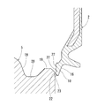
- FIG. 1A is a partial cross-sectional view showing a stage in which the seal is advanced in the axial direction from FIG. 1A and the seal lip portion is brought into contact with the inner ring.
- Sectional drawing which shows the bearing with seal which concerns on 1st Example of this invention 2 is an enlarged cross-sectional view near the seal lip portion of FIG. The figure which shows a mode that the seal lip part vicinity of FIG. 2 was seen from the bearing inner side to the axial direction
- Sectional drawing which shows the seal lip part vicinity which concerns on 2nd Example of this invention Sectional drawing which shows an example of a transmission provided with the bearing with a seal concerning this invention
- the seal held by the outer ring is in a non-contact posture with the inner ring, and the minimum clearance between the seal lip portion of the seal and the inner ring is set to be less than 0.1 mm. ing.
- Bearings for transmission use are required to achieve low friction while preventing foreign matter from entering the lubricating oil with a seal.
- the seal held by the outer ring is in contact with the inside of the seal groove portion at the seal lip portion, it is possible to suppress the entry of foreign matter, but the seal torque at the contact portion inhibits the reduction of friction.
- the seal held by the outer ring is in a non-contact posture with the inner ring, it is possible to achieve a significantly low friction by setting the seal torque to zero normally, but the seal lip and seal groove are Intrusion of foreign matter must be suppressed with the labyrinth seal to be formed.
- the minimum clearance between the seal lip portion and the inner ring is less than 0.1 mm.
- the conventional seal has a large resistance when the seal is inserted to fit the seal ring portion and the seal mounting portion, and the above-described minimum clearance of less than 0.1 mm can be set for the posture of the seal held in the outer ring by the fitting. It was difficult to manage.
- the present invention it is possible to manage the posture of the seal to such an extent that the minimum clearance of less than 0.1 mm can be set by reducing the resistance when the seal is inserted and improving the seal insertion property. . That is, according to the first embodiment, it is possible to achieve both reduction in friction and suppression of foreign matter intrusion, and the bearing with seal is suitable for transmission applications.
- a bearing 1 with a seal includes a seal 2 that seals the inside of the bearing with respect to the outside, an outer ring 4 having a seal mounting portion 3 that holds the seal 2, and an outer ring 4. And an inner ring 5 arranged coaxially.
- the central axis of the outer ring 4 and the central axis of the inner ring 5 are set coaxially.
- the “axial direction” refers to the direction along the central axis of the outer ring 4 and the inner ring 5
- the “radial direction” refers to the direction perpendicular to the axial direction. Means the circumferential direction around the central axis.
- the outer ring 4 is made of an annular member and has a raceway surface 6 on its inner periphery.
- the outer ring 4 is attached to a housing of another device.
- the inner ring 5 is made of an annular member and has a raceway surface 7 on the outer periphery thereof.
- a plurality of rolling elements 8 are interposed between the raceway surface 6 of the outer ring 4 and the raceway surface 7 of the inner ring 5.
- the circumferential interval between the rolling elements 8 is maintained by a cage 9.
- the outer ring 4, the inner ring 5, and the plurality of rolling elements 8 mainly constitute a rolling bearing that supports a radial load.
- the outer ring 4 is attached to a stationary member of another device.
- the inner ring 5 is attached to a shaft that is rotationally driven by another device.
- the outer ring 4 and the inner ring 5 have the illustrated cross-sectional shape over the entire circumference.
- the outer ring 4 and the inner ring 5 are each formed of steel, for example, bearing steel.
- the seal 2 includes a seal lip portion 10 formed in a generally tongue shape toward the radial direction, a ring portion 11 fitted to the seal mounting portion 3, and a dust formed in a tongue shape generally in the axial direction. And a lip portion 12.
- the seal 2 is held in a predetermined position by the seal mounting portion 3 in a predetermined posture shown in FIG. 2.
- the seal lip 10 and the dust lip 12 are each formed of an elastomer.
- the seal lip portion 10 may be formed of either a rubber material or a resin material.
- the ring portion 11 is reinforced with a cored bar 13.
- Elastomers such as the seal lip portion 10 and the dust removal lip portion 12 are formed by vulcanization molding and bonded to the core metal 13.
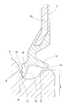
- FIG. 3 is an enlarged view of the vicinity of the seal lip 10.
- the surface of the seal lip portion 10 includes a lip tip 14 that is a portion that defines the diameter of the seal lip portion 10, an inner side surface 15 that is a surface portion on the inner side from the lip tip 14, It is comprised by the external side surface 16 which consists of the surface part of the external side from the front-end
- the vicinity of the lip tip 14 of the inner side surface 15 is in sliding contact with the rotating inner ring 5 and has a sealing action.
- a labyrinth clearance 17 is formed between the outer side surface 16 and the dust lip portion 12 and the inner ring 5.
- the seal mounting portion 3 is formed in a groove shape at the inner peripheral end of the outer ring 4 over the entire circumference.
- the inner ring 5 has a seal groove 20 defined by an inner groove wall 18 and an outer groove wall 19 over the entire circumference.
- the outer groove wall 19 and the seal mounting portion 3 form a seal inlet into which the seal 2 can be inserted in the axial direction.
- the groove shoulder of the outer groove wall 19 is lower than the inner groove wall 18, and the groove depth of the seal groove portion 20 extends from the groove bottom to the groove shoulder of the outer groove wall 19.
- the inner surface of the groove of the seal groove 20 is composed of the surfaces of the inner groove wall 18 and the outer groove wall 19 that are within the groove depth from the groove bottom.
- the surface portion of the inner groove wall 18 is a lip contact surface corresponding to the seal lip portion 10.
- the lip tip 14 of the seal lip portion 10 is positioned inside the seal groove portion 20, and the lip tip 14 of the inner side surface 15 is in contact with the surface portion of the inner groove wall 18 with a radial interference.
- the diameter A of the outer groove wall 19 is the diameter at the groove shoulder, and in the illustrated example, is the outer diameter of the groove shoulder.
- the diameter B of the seal lip 10 is the diameter at the lip tip 14 and is the inner diameter of the seal 2 in the illustrated example.
- the interference between the seal lip 10 and the outer groove wall 19 corresponds to (BA).
- the diameter B of the seal lip 10 is set to be less than 100% with respect to the diameter A of the outer groove wall 19. If the ratio B / A is set to 100% or more, the labyrinth clearance 17 cannot be formed by using the external groove wall 19, and the lip tip 14 of the seal lip portion 10 is made to the outside by the external groove wall 19. Therefore, the foreign matter can easily reach the contact portion between the vicinity of the lip tip 14 and the surface portion of the inner groove wall 18.
- the ratio B / A is generally set to 97% or more. If the ratio B / A is set to be less than 97%, the tightening allowance between the seal lip portion 10 and the outer groove wall 19 becomes too tight, and there is a concern that the mounting of the seal 2 becomes difficult.
- FIG. 1A shows an annular portion 11 and a seal mounting portion 3 by inserting a seal 2 in an axial direction into a seal insertion space between an outer ring 4 and an inner ring 5 arranged coaxially and press-fitting the ring portion 11 into the seal mounting portion 3.
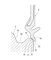
- FIG. 1B shows a state in which the insertion of the seal 2 further proceeds from the position of FIG.
- FIG. 4 shows a state in which the vicinity of the seal lip portion 10 in the natural state is viewed in the axial direction from the inner side.
- the inner side surface 15 of the seal lip portion 10 with the lip tip 14 as a boundary has an outer groove wall 19 and a seal lip portion when the ring portion 11 and the seal mounting portion 3 are fitted.
- a plurality of ridges 22 are formed between the 10 for securing the gap 21.
- These protrusions 22 are formed in circular shapes having different diameters, and are arranged at equal intervals in the radial direction. Each protrusion 22 extends over the entire circumference in the illustrated cross-sectional shape.
- the protrusion 22 located closest to the inner diameter of the seal 2 exists in the radial region corresponding to the tightening allowance (BA), and faces the outer groove wall 19 in the axial direction at the time of the aforementioned fitting.
- BA tightening allowance
- FIG. 1B when the protrusion 22 comes into contact with the outer groove wall 19 from the outside as the seal 2 is inserted in the axial direction, the protrusion 22 contacts the outer groove wall 19 along the protrusion 22.
- a gap 21 is formed in the gap.
- the protrusions 22 are also distributed in a radial region that approaches the outer diameter side from the radial region corresponding to the tightening allowance (BA).
- BA tightening allowance
- the cross-sectional shape of the protrusion 22 in the illustrated example is a solid semicircle. This is the direction in which the protrusion 22 and the external groove wall 19 are in point contact on the cross section when the ring portion 11 and the seal mounting portion 3 are fitted, and the seal lip portion 10 slides on the external groove wall 19. This is because the point contact state can be maintained in accordance with the change of.
- the reference of the protrusion amount of the ridge 22 is set from the inner peripheral surface 23 of the two peripheral surfaces forming the lip tip 14. What is necessary is just to determine suitably the cross-sectional shape and protrusion amount of the protrusion 22 so that the clearance gap 21 may be produced along self, while contacting with the external side groove wall 19.
- the sliding contact between the seal lip portion 10 and the external groove wall 19 when the ring portion 11 and the seal mounting portion 3 are fitted together causes the seal lip portion 10 to move to the external groove wall 19. It is limited to occur only between the protrusion 22 and the outer groove wall 19 in the entire period from the contact to the inner side of the seal groove 20 after the contact.
- This bearing 1 with a seal is as described above.
- the ring portion 11 of the seal 2 is fitted to the seal mounting portion 3 of the outer ring 4 shown in FIG. 2, as shown in FIG. Approaches the outer groove wall 19 of the seal groove portion 20 of the inner ring 5 in the axial direction from the outside.
- the protrusion 22 closest to the inner diameter comes into contact with the vicinity of the groove shoulder chamfer of the outer groove wall 19.
- the seal lip portion 10 gets over the groove shoulder of the outer side groove wall 19 while largely falling outward.
- the two or more ridges 22 of the fallen seal lip portion 10 come into contact with the outer groove wall 19, and a gap 21 is formed along these adjacent ridges 22, 22.
- the bearing with seal 1 can improve the seal insertion property until the seal lip portion 10 reaches the inside of the seal groove portion 20 when the seal 2 is mounted.
- the ratio B / A is set to 99.7%, but even if the setting is changed to be about 1% smaller, it becomes extremely difficult to insert the seal.
- the inventor of the present application confirmed that the ratio B / A of the conventional seal was changed to 98.5% and a prototype employing a plurality of protrusions as in the first embodiment.
- the ratio B / A is set to less than 97%. Is also possible.
- the bearing 1 with a seal can be easily formed by forming it integrally with the seal lip portion 10 because the protrusion 22 is formed on the seal lip portion 10, and the surface near the groove shoulder of the outer side groove wall 19.
- the shape can be a simple cylindrical surface or chamfered shape as before.
- the friction coefficient of the ridges 22 may be reduced by covering.
- FIG. 5 shows an enlarged view of the vicinity of the seal lip portion in the state of FIG. 2 in the second embodiment.
- the seal 2 held by the outer ring 4 is in a non-contact posture with the inner ring 5.
- the minimum clearance g between the seal lip portion 10 and the inner ring 5 of the seal 2 is generated between the lip tip 14 of the seal lip portion 10 and the inner groove wall 18 of the inner ring 5.
- the ratio B / A of the diameter B of the seal lip portion 10 and the diameter A of the outer groove wall 19 is set to 98% or more and less than 99% where good seal insertion property is confirmed. Yes.
- the minimum clearance g can be set to less than 0.1 mm for the posture of the seal 2 held on the outer ring 4.
- the labyrinth seal formed by the seal lip portion 10 and the seal groove portion 20 of the inner ring 5 has a minimum clearance g between the seal lip portion 10 and the inner ring 5 set to less than 0.1 mm. It is particularly narrow between the lip portions 10. For this reason, it is very difficult for foreign matter to pass through the minimum clearance g from the outside with the lip tip 14 as a boundary. Therefore, even if the non-contact type seal 2 is employed, foreign matter intrusion can be suppressed to such an extent that there is no fear of adversely affecting the bearing life.
- the bearing with a seal according to the second embodiment can achieve both low friction by reducing the seal torque of the seal 2 to zero, and suppression of foreign matter intrusion, and is suitable for transmission applications. It becomes a bearing with a good seal.
- the sealed bearing 1 can be used for supporting a shaft provided in a transmission for an automobile, for example.
- the transmission 100 illustrated in FIG. 6 is of a manual type, and an input shaft 102, an output shaft 103, and a pilot shaft 104 are arranged in series in a housing 101, and a counter shaft 105 and a reverse shaft 106 are connected to the output shaft 103.
- the structure is arranged in parallel.
- the reverse shaft 106 is also engaged with the output shaft 103.
- Each shaft 102 to 106 is provided with a large number of gear groups. By changing the meshing of these gear groups by a clutch hub 107 that is shifted by an external operation, the input shaft 102 is changed to the output shaft 103.
- the torque transmission path is appropriately selected.
- an input shaft 102, an output shaft 103, a pilot shaft 104, a counter shaft 105, and gear members 108 attached to one end side of the counter shaft 105 are supported by a bearing 1 with a seal.
- a bearing 1 with a seal for example, a vehicle differential, a constant velocity joint, a propeller shaft, a turbocharger, a machine work, etc. Application to machines, wind power generators, or wheel bearings.
Landscapes
- Engineering & Computer Science (AREA)
- General Engineering & Computer Science (AREA)
- Mechanical Engineering (AREA)
- Sealing With Elastic Sealing Lips (AREA)
- Sealing Of Bearings (AREA)
- Sealing Devices (AREA)
- Rolling Contact Bearings (AREA)
Abstract
シールリップ部(10)のうち、リップ先端(14)を境とした内部側に、複数の突条(22)を互いに径の異なる円形状に形成する。これら突条(22)は、シール(2)の環部(11)と外輪(4)のシール装着部(3)の嵌合時にシール(2)と内輪(5)のシール溝部(20)の外部側溝壁(19)の接触箇所を突条(22)のみに制限するように分布している。これにより、前述の嵌合時に突条(22)に沿って隙間(21)が生じて、外部側溝壁(19)とシールリップ部(10)間のすべり面積を少なくなるようにする。
Description
この発明は、軸受内部空間と外部を仕切るシールを備えるシール付軸受に関する。
例えば、自動車、各種建設用機械等の車両に搭載されたトランスミッション内にはギアの摩耗粉等の異物が混在する。このため、トランスミッション内の軸受においては、シールにより、軸受内部への異物侵入を防ぎ、軸受の早期破損が防止されている。
シールは、一般に、シールリップ部と、外輪のシール装着部に嵌合する環部とをもっている。外輪に対して相対回転させられる内輪には、周方向全周に亘るシール溝部が形成されている。シール溝部の外部側溝壁とシール装着部とが、シールを軸方向に挿入可能なシール入口を形成している。シールリップ部のリップ先端は、シール溝部の内側に位置する。シールリップ部の内部側面とシール溝部の内部側溝壁とが協働して密封作用を奏する。シール溝部の外部側溝壁は、シールリップ部のリップ先端を外部に対して遮蔽する。さらに耐異物侵入性・耐泥水性を高めるため、シールリップ部とシール溝部の外部側溝壁間を利用したラビリンスすきまが設けられることもある(下記特許文献1)。
しかしながら、シールの環部をシール装着部に嵌合する際、シールリップ部のリップ先端がシール溝部の内側へ到達する前の段階で、シールリップ部の内部側面が周方向全周に亘って軸方向からシール溝部の外部側溝壁に強く擦り付けられる。一般に、シールリップ部はエラストマで形成され、外輪や内輪は軸受鋼等の鋼で形成されるので、シールリップ部の内部側面がシール溝部の外部側溝壁に強く擦り付けられた際、大きな摩擦力がシール挿入の抵抗となる。このため、シールリップ部やシール溝部の外部側溝壁の径寸は、シールを適切に挿入可能な程度に設定する必要があり、耐異物侵入性や耐泥水性を向上させるための形状工夫が制限されていた。
上述の背景に鑑み、この発明が解決しようとする課題は、外輪のシール装着部にシールの環部を嵌合する際にシールリップ部が内輪のシール溝部の内側へ至るまでのシール挿入性を向上させることである。
上記の課題を達成するため、この発明は、軸受内部を外部に対して密封するシールと、前記シールを保持するシール装着部をもった外輪と、前記外輪と同軸に配置された内輪とを備え、前記内輪が、周方向全周に亘るシール溝部を有し、前記シールが、前記シール溝部の内側に位置するリップ先端をもったシールリップ部と、前記シール装着部に嵌合する環部とを有するシール付軸受において、前記シールリップ部のうち、前記リップ先端を境とした内部側に、複数の突条が互いに径の異なる円形状に形成されており、前記複数の突条が、前記環部と前記シール装着部の嵌合時に前記シールと前記シール溝部の外部側溝壁の接触箇所を前記突条のみに制限するように分布している、という構成を採用したものである。
上記構成によれば、外輪のシール装着部にシールの環部を嵌合する際、シールリップ部は、内輪のシール溝部の外部側溝壁に対して外部側から接触し、外部側へ倒れた状態で外部側溝壁を乗り越えていく。この際、シールリップ部は、リップ先端を境とした内部側に形成された円形状の突条のみでシール溝部の外部側溝壁と接触するため、その突条に沿って外部側溝壁及びシールリップ部間に隙間が生じる。円形状の突条は外部側溝壁と周方向に均等に接触することが可能なため、突条によってシールの姿勢崩れが生じ易くなる懸念はない。複数の突条が互いに径の異なる円形状に存在しているので、シールリップ部が外部側へ倒れても、二つ以上の突条において外部側溝壁と接触することができ、これら突条に沿って前述の隙間が生じる。円形状の突条に沿ってシールリップ部及び外部側溝壁間に隙間が生じることでシールリップ部とシール溝部の外部側溝壁間のすべり面積が少なくなり、シール挿入に抵抗する摩擦力が低減する。
このように、この発明は、上記構成の採用により、外輪のシール装着部にシールの環部を嵌合する際にシールリップ部が内輪のシール溝部の内側へ至るまでのシール挿入性を向上させることができる。
この発明の好ましい実施形態を説明する。
第一実施形態では、前記外輪に保持された前記シールが、前記内輪と非接触の姿勢になっており、当該シールの前記シールリップ部及び前記内輪間の最小すきまが0.1mm未満に設定されている。
第一実施形態では、前記外輪に保持された前記シールが、前記内輪と非接触の姿勢になっており、当該シールの前記シールリップ部及び前記内輪間の最小すきまが0.1mm未満に設定されている。
トランスミッション用途の軸受には、潤滑油中の異物侵入をシールで防止しつつ、低フリクション化を図ることが求められている。外輪に保持されたシールがシールリップ部においてシール溝部の内側と接した姿勢になっている場合、異物侵入を抑制することは可能だが、その接触部でのシールトルクが低フリクション化を阻害する。これに対し、外輪に保持されたシールが内輪と非接触の姿勢になっている場合、シールトルクを通常、零にして著しい低フリクション化を実現することは可能だが、シールリップ部及びシール溝部が形成するラビリンスシールで異物侵入を抑制しなければならない。満足なラビリンスシールを実現するには、シールリップ部及び内輪間の最小すきまを0.1mm未満に設定することが好ましい。従来シールでは、シールの環部とシール装着部を嵌合するシール挿入時の抵抗が大きく、その嵌合で外輪に保持されたシールの姿勢について、前述の0.1mm未満の最小すきまを設定できる程に管理することが困難であった。
一方、この発明では、シール挿入時の抵抗を小さくしてシール挿入性を向上させることにより、前述の0.1mm未満の最小すきまを設定可能な程度にシールの姿勢を管理することが可能となる。すなわち、第一実施形態によれば、低フリクション化を図ることと、異物侵入の抑制とを両立させることができ、トランスミッション用途に好適なシール付軸受となる。
一方、この発明では、シール挿入時の抵抗を小さくしてシール挿入性を向上させることにより、前述の0.1mm未満の最小すきまを設定可能な程度にシールの姿勢を管理することが可能となる。すなわち、第一実施形態によれば、低フリクション化を図ることと、異物侵入の抑制とを両立させることができ、トランスミッション用途に好適なシール付軸受となる。
この発明に係る第一実施例を添付図面に基づいて説明する。図2に示すように、第一実施例に係るシール付軸受1は、軸受内部を外部に対して密封するシール2と、シール2を保持するシール装着部3をもった外輪4と、外輪4と同軸に配置された内輪5とを備える。ここで、外輪4の中心軸と、内輪5の中心軸とは同軸に設定されている。以下、「軸方向」とは、外輪4及び内輪5の中心軸に沿った方向のことをいい、「径方向」とは、その軸方向に直角な方向のことをいい、「周方向」とは、その中心軸周りの円周方向のことをいう。
外輪4は、環状部材からなり、その内周に軌道面6をもっている。外輪4は、他装置のハウジングに取り付けられる。内輪5は、環状部材からなり、その外周に軌道面7をもっている。外輪4の軌道面6及び内輪5の軌道面7間に複数の転動体8が介在している。転動体8間の周方向間隔は、保持器9によって保たれている。外輪4、内輪5、複数の転動体8は、主としてラジアル荷重を支持する転がり軸受を構成している。外輪4は、他装置の静止部材に取り付けられる。内輪5は、他装置によって回転駆動される軸に取り付けられる。なお、外輪4及び内輪5は、周方向全周に亘って図示の断面形状をもっている。
外輪4及び内輪5は、それぞれ鋼、例えば軸受鋼によって形成されている。
シール2は、概ね径方向に向けて舌片状に形成されたシールリップ部10と、シール装着部3に嵌合する環部11と、概ね軸方向に向けて舌片状に形成された塵除けリップ部12とを有する。環部11がシール装着部3に圧入嵌合されることにより、シール2がシール装着部3によって、図2に示す所定の姿勢で所定位置に保持された状態となる。
シールリップ部10、塵除けリップ部12は、それぞれエラストマにより形成されている。シールリップ部10は、ゴム材料又は樹脂材料のいずれで形成してもよい。環部11は、芯金13で補強されている。シールリップ部10、塵除けリップ部12等のエラストマは、加硫成型によって形成されると共に芯金13に接着されている。
図3にシールリップ部10付近を拡大図示する。同図に示すように、シールリップ部10の表面は、シールリップ部10の径寸を規定する部位であるリップ先端14と、リップ先端14から内部側の表面部分からなる内部側面15と、リップ先端14から外部側の表面部分からなる外部側面16とで構成されている。内部側面15のリップ先端14付近は、回転する内輪5とすべり接触して密封作用を奏する。外部側面16及び塵除けリップ部12は、内輪5との間にラビリンスすきま17を形成する。
シール装着部3は、外輪4の内周端部で周方向全周に亘る溝状に形成されている。
内輪5は、周方向全周に亘る内部側溝壁18及び外部側溝壁19によって規定されたシール溝部20を有する。外部側溝壁19とシール装着部3とが、シール2を軸方向に挿入可能なシール入口を形成している。図示例では、外部側溝壁19の溝肩が、内部側溝壁18よりも低くなっており、シール溝部20の溝深さは、溝底から外部側溝壁19の溝肩までとなっている。シール溝部20の溝内側面は、その溝底から当該溝深さ内にある内部側溝壁18及び外部側溝壁19の表面からなる。
シール溝部20の溝内面のうち、内部側溝壁18の表面部分は、シールリップ部10に対応のリップ当り面になっている。シールリップ部10のリップ先端14は、シール溝部20の内側に位置し、内部側面15のリップ先端14は、径方向の締め代をもって内部側溝壁18の表面部分に接触している。
外部側溝壁19の径寸Aは、溝肩での径であり、図示例では溝肩の外径となる。シールリップ部10の径寸Bは、リップ先端14での径であり、図示例ではシール2の内径となる。シールリップ部10と外部側溝壁19間の締め代は(B-A)に相当する。
シールリップ部10の径寸Bは、外部側溝壁19の径寸Aに対して100%未満に設定されている。比率B/Aを100%以上に設定すると、外部側溝壁19を利用してラビリンスすきま17を形成することができず、また、外部側溝壁19によってシールリップ部10のリップ先端14を外部に対して軸方向に遮蔽することもできないため、異物がリップ先端14付近と内部側溝壁18の表面部分との接触箇所へ到達し易くなってしまう。比率B/Aは、一般に、97%以上に設定されている。比率B/Aを97%未満に設定すると、シールリップ部10と外部側溝壁19間の締め代設定がきつくなり過ぎ、シール2の装着困難化を招く懸念がある。
図1Aは、同軸に配置された外輪4及び内輪5間のシール挿入空間へシール2を軸方向に挿入し、環部11をシール装着部3に圧入することによって環部11とシール装着部3を嵌合状態とするシール嵌合工程において、シールリップ部10が内輪5に接触する直前の様子を示す。図1Bは、図1Aの位置からシール2の挿入がさらに進み、シールリップ部10が外部側溝壁19にすべり接触する様子を示す。図4に、自然状態のシールリップ部10付近を内部側から軸方向に視た様子を示す。
図1A、図4に示すように、シールリップ部10のうち、リップ先端14を境とした内部側面15には、環部11とシール装着部3の嵌合時に外部側溝壁19及びシールリップ部10間に隙間21を確保するための複数の突条22が形成されている。これら突条22は、互いに径の異なる円形状に形成されており、径方向に均等間隔で並んでいる。各突条22は、図示の断面形状で周方向全周に亘っている。シール2の最も内径寄りに位置する突条22は、締め代(B-A)に対応の径方向領域に存在しており、前述の嵌合時に外部側溝壁19と軸方向に向き合う。図1Bから明らかなように、シール2の軸方向への挿入に伴って、突条22が外部側溝壁19に外部側から接触したとき、その突条22に沿って外部側溝壁19との間に隙間21が生じる。
図1A、図3から明らかなように、突条22は、締め代(B-A)に対応の径方向領域から外径側に寄った径方向領域にも分布している。これは、図1Bに示すように、シールリップ部10の内部側面15が外部側溝壁19に強く擦り付けられることでシールリップ部10が全体的に外部側へ倒れたときでも、シールリップ部10と外部側溝壁19の接触箇所を突条22のみに制限するためである。
図示例の突条22の断面形状は中実半円状になっている。これは、環部11とシール装着部3の嵌合時に突条22と外部側溝壁19が当該断面上で点接触様になるようにすると共に、シールリップ部10が外部側溝壁19を滑る方向の変化に応じて当該点接触様を維持可能とするためである。突条22の突出量の基準は、リップ先端14を形成する二つの周面のうち、内部側の周面23から設定されている。突条22の断面形状及び突出量は、外部側溝壁19と接触している間、自己に沿って隙間21を生じさせ得るように適宜に定めればよい。
上述のような突条22の分布態様の採用により、環部11とシール装着部3の嵌合時におけるシールリップ部10と外部側溝壁19のすべり接触は、シールリップ部10を外部側溝壁19に接触させてからシール溝部20の内側に至らせるまでの全期間において、突条22及び外部側溝壁19間のみで生じるように制限されている。
このシール付軸受1は、上述のようなものであり、図2に示す外輪4のシール装着部3にシール2の環部11を嵌合する際、図1Aに示すように、シールリップ部10が内輪5のシール溝部20の外部側溝壁19に対して外部側から軸方向に接近し、先ず、最も内径寄りの突条22のみが外部側溝壁19の溝肩面取り付近に接触する。そして、さらにシール2の挿入が進むと、図1Bに示すように、シールリップ部10が外部側へ大きく倒れながら、外部側溝壁19の溝肩を乗り越えていく。倒れたシールリップ部10の二つ以上の突条22において外部側溝壁19と接触し、これら隣り合う突条22、22に沿って隙間21が生じる。円形状の突条22は外部側溝壁19と周方向に均等に接触するため、突条22によってシール2の姿勢崩れが生じ易くなる懸念はない。円形状の突条22に沿ってシールリップ部10及び外部側溝壁19間に隙間が生じることでシールリップ部10と外部側溝壁19間のすべり面積が少なくなり、シール挿入に抵抗する摩擦力が低減する。したがって、このシール付軸受1は、シール2の装着時にシールリップ部10がシール溝部20の内側へ至るまでのシール挿入性を向上させることができる。
例えば、従来シールとして、比率B/Aを99.7%に設定したものがあるが、これを1%程度小さく設定変更しただけでも、シール挿入が著しく困難となる。本願発明者が、その従来シールにおいて比率B/Aを98.5%に設定変更すると共に第一実施例のような複数の突条を採用した試作品で確認したところ、それでも良好なシール装着性を得ることができた。このように、この発明によれば、比率B/Aを従来から1%程度小さく設定可能な程度にシール挿入性を向上させることができ、例えば、比率B/Aを97%未満に設定することも可能となる。
また、このシール付軸受1は、突条22をシールリップ部10に形成するため、シールリップ部10と一体に成形することで簡単に形成可能であり、外部側溝壁19の溝肩付近の表面形状を従来と同様に簡単な円筒面状、面取り状にすることができる。
なお、突条22の摩擦係数を低くすることが好ましいのは勿論であり、突条22を形成するエラストマへの表面処理、例えば、当該エラストマよりも硬い熱硬化塗料等の被膜で突条22を覆って摩擦係数を低くしてもよい。
この発明の第二実施例に係るシール付軸受を説明する。
第二実施例に係るシール付軸受は、シールを非接触式シールに変更した点でのみ第一実施例と相違している。このため、以下では、第一実施例の説明で用いた図面を引き続き適宜に参照すると共に、共通の符号を用いる。第二実施例の図2の状態でのシールリップ部付近の拡大図を図5に示す。
第二実施例に係るシール付軸受は、シールを非接触式シールに変更した点でのみ第一実施例と相違している。このため、以下では、第一実施例の説明で用いた図面を引き続き適宜に参照すると共に、共通の符号を用いる。第二実施例の図2の状態でのシールリップ部付近の拡大図を図5に示す。
図2、図5に示すように、第二実施例においては、外輪4に保持されたシール2は、内輪5と非接触の姿勢になっている。そのシール2のシールリップ部10及び内輪5間の最小すきまgは、シールリップ部10のリップ先端14と内輪5の内部側溝壁18との間において生じるようになっている。
第二実施例においては、シールリップ部10の径寸Bと外部側溝壁19の径寸Aの比率B/Aを、良好なシール挿入性が確認された98%以上99%未満に設定している。これにより、外輪4に保持されたシール2の姿勢について最小すきまgを0.1mm未満に設定可能としている。軸受運転中、通常、シール2と内輪5が接触せず、シールトルクが零の状態に保たれる。
また、シールリップ部10と内輪5のシール溝部20が形成するラビリンスシールは、シールリップ部10と内輪5間の最小すきまgを0.1mm未満に設定しているので、内部側溝壁18とシールリップ部10間で特に狭くなっている。このため、リップ先端14を境とした外部側から異物が最小すきまgを通過することは非常に困難となる。したがって、非接触式のシール2を採用しても、軸受寿命に悪影響を及ぼす心配のない程度に異物侵入を抑制することができる。
このように、第二実施例に係るシール付軸受は、シール2のシールトルクを通常、零にして低フリクション化を図ることと、異物侵入の抑制とを両立させることができ、トランスミッション用途に好適なシール付軸受となる。
このシール付軸受1は、例えば、自動車用のトランスミッションに備わる軸の支持に利用することができる。図6に例示するトランスミッション100は、マニュアル式のものであり、ハウジング101内にインプットシャフト102、アウトプットシャフト103およびパイロットシャフト104を直列に配置し、さらにカウンターシャフト105とリバースシャフト106をアウトプットシャフト103と平行に配置した構造になっている。リバースシャフト106は、アウトプットシャフト103とも係合するようになっている。各シャフト102~106には多数のギア群が設けられており、外部からの操作でシフトされるクラッチハブ107で、これらのギア群の噛み合わせを変えることにより、インプットシャフト102からアウトプットシャフト103へのトルク伝達経路が適切に選択されるようになっている。このトランスミッション100では、インプットシャフト102、アウトプットシャフト103、パイロットシャフト104、カウンターシャフト105、およびカウンターシャフト105の一端側に取り付けられたギア部材108が、それぞれシール付軸受1で支持されている。なお、シール付軸受1の用途として、トランスミッション100に組み込まれている例を示したが、シール付軸受1の他の用途として、例えば、車両のディファレンシャル、等速ジョイント、プロペラシャフト、ターボチャージャ、工作機械、風力発電機、又はホイール軸受への適用が挙げられる。
今回開示された実施形態及び実施例はすべての点で例示であって制限的なものではないと考えられるべきである。したがって、本発明の範囲は上記した説明ではなくて特許請求の範囲によって示され、特許請求の範囲と均等の意味および範囲内でのすべての変更が含まれることが意図される。
1 シール付軸受
2 シール
3 シール装着部
4 外輪
5 内輪
10 シールリップ部
11 環部
14 リップ先端
18 内部側溝壁
19 外部側溝壁
20 シール溝部
21 隙間
22 突条
100 トランスミッション
2 シール
3 シール装着部
4 外輪
5 内輪
10 シールリップ部
11 環部
14 リップ先端
18 内部側溝壁
19 外部側溝壁
20 シール溝部
21 隙間
22 突条
100 トランスミッション
Claims (5)
- 軸受内部を外部に対して密封するシールと、前記シールを保持するシール装着部をもった外輪と、前記外輪と同軸に配置された内輪とを備え、
前記内輪が、周方向全周に亘るシール溝部を有し、
前記シールが、前記シール溝部の内側に位置するリップ先端をもったシールリップ部と、前記シール装着部に嵌合する環部とを有するシール付軸受において、
前記シールリップ部のうち、前記リップ先端を境とした内部側に、複数の突条が互いに径の異なる円形状に形成されており、
前記複数の突条が、前記環部と前記シール装着部の嵌合時に前記シールと前記シール溝部の外部側溝壁の接触箇所を前記突条のみに制限するように分布していることを特徴とするシール付軸受。 - 前記外輪に保持された前記シールが前記内輪と非接触の姿勢になっており、当該シールの前記シールリップ部及び前記内輪間の最小すきまが、0.1mm未満に設定されている請求項1に記載のシール付軸受。
- 前記シールリップ部の径寸が、前記シール溝部の外部側溝壁の径寸に対して97%以上100%未満に設定されている請求項1又は2に記載のシール付軸受。
- 前記シールリップ部がゴム材料又は樹脂材料によって形成されている請求項1から3のいずれか1項に記載のシール付軸受。
- 車両のトランスミッションに組み込まれている請求項1から4のいずれか1項に記載のシール付軸受。
Applications Claiming Priority (2)
| Application Number | Priority Date | Filing Date | Title |
|---|---|---|---|
| JP2016071131A JP6727002B2 (ja) | 2016-03-31 | 2016-03-31 | シール付軸受 |
| JP2016-071131 | 2016-03-31 |
Publications (1)
| Publication Number | Publication Date |
|---|---|
| WO2017169976A1 true WO2017169976A1 (ja) | 2017-10-05 |
Family
ID=59965287
Family Applications (1)
| Application Number | Title | Priority Date | Filing Date |
|---|---|---|---|
| PCT/JP2017/011204 Ceased WO2017169976A1 (ja) | 2016-03-31 | 2017-03-21 | シール付軸受 |
Country Status (2)
| Country | Link |
|---|---|
| JP (1) | JP6727002B2 (ja) |
| WO (1) | WO2017169976A1 (ja) |
Cited By (1)
| Publication number | Priority date | Publication date | Assignee | Title |
|---|---|---|---|---|
| US20230072798A1 (en) * | 2021-09-09 | 2023-03-09 | Aktiebolaget Skf | Bearing seal and a bearing with the same |
Families Citing this family (2)
| Publication number | Priority date | Publication date | Assignee | Title |
|---|---|---|---|---|
| KR102580857B1 (ko) * | 2018-12-28 | 2023-09-22 | 주식회사 베어링아트 | 씰링성이 향상된 구름 베어링 |
| KR102604188B1 (ko) | 2019-04-03 | 2023-11-23 | 주식회사 베어링아트 | 씰링성이 향상된 구름 베어링 |
Citations (2)
| Publication number | Priority date | Publication date | Assignee | Title |
|---|---|---|---|---|
| JP2001146923A (ja) * | 1999-09-10 | 2001-05-29 | Nsk Ltd | 密封形転がり軸受 |
| JP2010112472A (ja) * | 2008-11-06 | 2010-05-20 | Ntn Corp | シール付き軸受 |
Family Cites Families (2)
| Publication number | Priority date | Publication date | Assignee | Title |
|---|---|---|---|---|
| JP2009264401A (ja) * | 2008-04-22 | 2009-11-12 | Nsk Ltd | 通電式転がり軸受 |
| JP5600689B2 (ja) * | 2009-01-28 | 2014-10-01 | フェデラル−モーグル コーポレイション | ラジアルシャフトシール、ラジアルシャフトシールアセンブリおよび設置方法 |
-
2016
- 2016-03-31 JP JP2016071131A patent/JP6727002B2/ja not_active Expired - Fee Related
-
2017
- 2017-03-21 WO PCT/JP2017/011204 patent/WO2017169976A1/ja not_active Ceased
Patent Citations (2)
| Publication number | Priority date | Publication date | Assignee | Title |
|---|---|---|---|---|
| JP2001146923A (ja) * | 1999-09-10 | 2001-05-29 | Nsk Ltd | 密封形転がり軸受 |
| JP2010112472A (ja) * | 2008-11-06 | 2010-05-20 | Ntn Corp | シール付き軸受 |
Cited By (2)
| Publication number | Priority date | Publication date | Assignee | Title |
|---|---|---|---|---|
| US20230072798A1 (en) * | 2021-09-09 | 2023-03-09 | Aktiebolaget Skf | Bearing seal and a bearing with the same |
| US12331785B2 (en) * | 2021-09-09 | 2025-06-17 | Aktiebolaget Skf | Bearing seal and a bearing with the same |
Also Published As
| Publication number | Publication date |
|---|---|
| JP6727002B2 (ja) | 2020-07-22 |
| JP2017180739A (ja) | 2017-10-05 |
Similar Documents
| Publication | Publication Date | Title |
|---|---|---|
| US20100066030A1 (en) | Hermetic sealing device | |
| JP2017207124A (ja) | 車輪用軸受装置 | |
| CN109983244B (zh) | 密封装置以及轮毂轴承 | |
| CN102203445B (zh) | 带有密封件的轴承 | |
| JP6457087B2 (ja) | 密封装置 | |
| CN105605103A (zh) | 轮毂轴承单元 | |
| CN108119560B (zh) | 具有改进的密封装置的滚动轴承 | |
| EP3511588B1 (en) | Sealed bearing | |
| JP2018119580A (ja) | クリープ防止転がり軸受 | |
| WO2017169976A1 (ja) | シール付軸受 | |
| JP6959628B2 (ja) | 軸受密封装置 | |
| US20210010532A1 (en) | Bearing device for wheels | |
| JP2005325867A (ja) | 鉄道車両用軸受 | |
| US9279456B2 (en) | Housing mounted external bearing shield | |
| KR102075472B1 (ko) | 구름 베어링용 카트리지 씰 | |
| KR20210111743A (ko) | 구름 베어링용 씰 및 슬링거 | |
| JP6722517B2 (ja) | 密封装置 | |
| JP6939230B2 (ja) | シール機構 | |
| WO2018159809A1 (ja) | オイルシール及びシール付軸受 | |
| JP2016070306A (ja) | 密封型転がり軸受 | |
| JP2008075832A (ja) | 転がり軸受装置 | |
| JP5625539B2 (ja) | 密封形転がり軸受 | |
| JP2014196798A (ja) | 転がり軸受 | |
| JP2009014181A (ja) | シール構造及びその製造方法並びに軸受ユニット | |
| JP2026044156A (ja) | 転がり軸受 |
Legal Events
| Date | Code | Title | Description |
|---|---|---|---|
| NENP | Non-entry into the national phase |
Ref country code: DE |
|
| 121 | Ep: the epo has been informed by wipo that ep was designated in this application |
Ref document number: 17774517 Country of ref document: EP Kind code of ref document: A1 |
|
| 122 | Ep: pct application non-entry in european phase |
Ref document number: 17774517 Country of ref document: EP Kind code of ref document: A1 |