WO2017169999A1 - 化粧パネル取付構造 - Google Patents
化粧パネル取付構造 Download PDFInfo
- Publication number
- WO2017169999A1 WO2017169999A1 PCT/JP2017/011304 JP2017011304W WO2017169999A1 WO 2017169999 A1 WO2017169999 A1 WO 2017169999A1 JP 2017011304 W JP2017011304 W JP 2017011304W WO 2017169999 A1 WO2017169999 A1 WO 2017169999A1
- Authority
- WO
- WIPO (PCT)
- Prior art keywords
- boss
- receiving portion
- claw
- auxiliary
- decorative panel
- Prior art date
- Legal status (The legal status is an assumption and is not a legal conclusion. Google has not performed a legal analysis and makes no representation as to the accuracy of the status listed.)
- Ceased
Links
Images


Classifications
-
- F—MECHANICAL ENGINEERING; LIGHTING; HEATING; WEAPONS; BLASTING
- F24—HEATING; RANGES; VENTILATING
- F24F—AIR-CONDITIONING; AIR-HUMIDIFICATION; VENTILATION; USE OF AIR CURRENTS FOR SCREENING
- F24F7/00—Ventilation
- F24F7/04—Ventilation with ducting systems, e.g. by double walls; with natural circulation
- F24F7/06—Ventilation with ducting systems, e.g. by double walls; with natural circulation with forced air circulation, e.g. by fan positioning of a ventilator in or against a conduit
- F24F7/10—Ventilation with ducting systems, e.g. by double walls; with natural circulation with forced air circulation, e.g. by fan positioning of a ventilator in or against a conduit with air supply, or exhaust, through perforated wall, floor or ceiling
-
- F—MECHANICAL ENGINEERING; LIGHTING; HEATING; WEAPONS; BLASTING
- F24—HEATING; RANGES; VENTILATING
- F24F—AIR-CONDITIONING; AIR-HUMIDIFICATION; VENTILATION; USE OF AIR CURRENTS FOR SCREENING
- F24F13/00—Details common to, or for air-conditioning, air-humidification, ventilation or use of air currents for screening
- F24F13/20—Casings or covers
Definitions
- the present invention relates to a decorative panel mounting structure for mounting on a ceiling or the like.
- the decorative panel is detachably attached, for example, covering the indoor opening of the air supply grill fixed to the ceiling. That is, in the decorative panel mounting structure, generally, a fitting portion made of a resin material formed on the decorative panel is fitted to the indoor side of the air supply grill body.
- FIG. 8 is a side sectional view showing a conventional decorative panel mounting structure.
- the attachment structure of the decorative panel 101 includes a boss portion 103 and a boss receiving portion 105.
- the boss 103 is provided as a protrusion on either the back surface of the decorative panel 101 or the frame 102.
- the boss receiving portion 105 is fitted with the boss portion 103.
- the boss receiving portion 105 includes an engaging portion 104 that engages with a protrusion provided on the boss portion 103.
- only one set of the boss portion 103 and the boss receiving portion 105 has a structure that prevents the decorative panel 101 from falling.
- the fitting state between the boss portion 103 and the boss receiving portion 105 having the fall prevention structure does not change.
- a change occurs in the fitting state of the boss portion 103 and the boss receiving portion 105 that are not provided with the fall prevention mechanism.
- an abnormality appears in the holding posture of the decorative panel 101, and the defect is easily noticed visually (see, for example, Patent Document 1).
- the boss part itself is applied with its own weight even if the nail that does not apply its own weight deteriorates slowly. Degradation is progressing.
- the decorative panel is heavy due to an increase in the size of the decorative panel or the like, the boss itself may not be able to withstand deterioration, and measures using only the nails are insufficient.
- an object of the present invention is to provide a decorative panel mounting structure that can prevent a drop due to deterioration of a boss portion even if the decorative panel is enlarged.
- the decorative panel mounting structure which concerns on this invention engages the boss
- the structure further includes an auxiliary boss portion and an auxiliary boss receiving portion that are engaged independently of the engagement of the boss portion and the boss receiving portion.
- the boss part and the boss receiving part have an engaging structure that engages with each other.
- the auxiliary boss portion and the auxiliary boss receiving portion include an engagement auxiliary structure that engages only when the engagement by the engagement structure is released. This achieves the intended purpose.
- the weight of the auxiliary boss is not normally applied to the auxiliary boss, the fall of the boss can be prevented even if the decorative panel is enlarged.
- FIG. 1 is an exploded perspective view of a ventilation device according to the present invention.
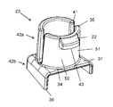
- FIG. 2 is a perspective view of a boss portion according to the present invention.
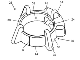
- FIG. 3 is a perspective view of a boss receiving portion according to the present invention.
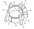
- FIG. 4 is a perspective view of an auxiliary boss receiving portion according to the present invention.
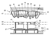
- FIG. 5 is a side view showing the relationship between the boss portion, the boss receiving portion, the auxiliary boss portion, and the auxiliary boss receiving portion according to the present invention.
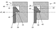
- FIG. 6 is a cross-sectional view showing an engagement structure and an auxiliary engagement structure according to the present invention.
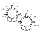
- FIG. 7 is a diagram showing a positional relationship between the boss receiving portion and the auxiliary boss receiving portion according to the present invention.
- FIG. 8 is a side sectional view showing a conventional decorative panel mounting structure.
- FIG. 1 is an exploded perspective view of a ventilation device according to the present invention.
- the ventilation device 100 includes a main body frame 1, an electric motor 9, a fan casing 13, a louver base 18, and a decorative panel 20.
- the main body frame 1 is, for example, a resin-made polypropylene box shape that is easy to process, and the lower surface 2 is provided with a flange portion 3. Further, for example, a rectangular opening 5 that functions as the air inlet 4 is provided at the center of the lower surface 2 of the main body frame 1. Furthermore, the side surface 6 of the main body frame 1 is provided with, for example, a rectangular opening that functions as the exhaust port 7.
- the electric motor 9 has a rotating shaft 10 and drives a centrifugal blower blade 11 which is a sirocco fan described later.
- the electric motor 9 is attached to the top surface 8 with screws (not shown) or the like so that the rotation shaft 10 is perpendicular to the top surface 8 of the main body frame 1.
- the electric motor 9 is fixed to the top surface 8 using, for example, a spinner.
- the fan casing 13 has a centrifugal blower blade 11 which is a sirocco fan inside.
- the side surface 12 of the fan casing 13 has a scroll shape, and is attached to the inside of the main body frame 1 with screws or the like.
- the lower surface 16 of the fan casing 13 is provided with a suction port 14 having an orifice 15.
- the bell mouth 17 is provided on the lower surface of the louver base 18 so as to cover the air inlet 4 and is fixed to the flange portion 3 with screws (not shown) or the like.
- the louver base 18 has, for example, a rectangular plate shape, and has a boss receiving portion 25 and an auxiliary boss receiving portion 26 on the lower surface. Details of the boss receiving portion 25 and the auxiliary boss receiving portion 26 will be described later.
- the decorative panel 20 is rectangular and has a boss portion 23 and an auxiliary boss portion 27 on a surface facing the louver base 18.
- the decorative panel 20 is fixed to the louver base 18 via the boss portion 23. Details of the boss portion 23 and the auxiliary boss portion 27 will be described later.
- boss portion 23 and the boss receiving portion 25 which are the attachment structure 19 between the louver base 18 and the decorative panel 20 will be described.
- FIG. 2 is a perspective view of a boss portion according to the present invention.
- the boss portion 23 includes a cylindrical portion 42a having a hollow cylindrical shape and a pedestal portion 42b.
- the cylindrical part 42a has the key-like nail
- the claw 22 protrudes in a direction away from the center of the cylindrical shape of the boss portion 23, starting from the outer surface 51 of the side wall 50 of the boss portion 23.
- the claw 22 has a structure that engages with a main claw receiving portion 24 (see FIG. 4) provided in the boss receiving portion 25. Details of the engagement structure between the boss portion 23 and the boss receiving portion 25 will be described later.
- the notch 41 is provided in the side wall 50 of the cylindrical part 42a.
- the notch 41 is engaged with the main claw receiving portion 24 of the claw 22, in other words, when the boss portion 23 is fitted to the boss receiving portion 25, the protruding claw 22 is pushed into the cylindrical inner direction. It has a function of absorbing the generated distortion.
- the pedestal portion 42b has an inverted U shape in a cross-sectional view, and the inverted U-shaped end portion 36 is connected to the back surface 21 (the surface facing the louver base 18) of the decorative panel 20. Thereby, the boss part 23 is connected to the decorative panel 20. Further, the cylindrical portion 42 a is connected to the top surface 37 of the pedestal portion 42 b via the lower end portion 34.
- the structure, size, etc. of the boss portion 23 and the auxiliary boss portion 27 are the same. Therefore, the description of the auxiliary boss portion 27 is omitted.
- FIG. 3 is a perspective view of a boss receiving portion according to the present invention.
- the boss receiving portion 25 has a hollow cylindrical shape, and includes a main claw receiving portion 24 that engages with the claw 22 on the inner surface 52 of the side wall 30.
- the boss receiving portion 25 includes a reinforcing rib 32 on the outer surface 53 of the side wall 30 in the cylindrical shape.
- the reinforcing rib 32 protrudes from the outer surface 53 of the boss receiving portion 25 in the direction away from the center of the cylindrical shape of the boss receiving portion 25, and is provided to increase the strength of the boss receiving portion 25.
- the reinforcing rib 32 includes a curved surface 31 that protrudes from the end surface 38 of the boss receiving portion 25 toward the boss portion 23 during fitting. In the present embodiment, four reinforcing ribs 32 are provided, but the present invention is not limited to this.
- the boss portion 23 and the boss receiving portion 25 are fitted. Specifically, the boss portion 23 and the boss receiving portion 25 are fixed by fitting the outer surface 51 of the boss portion 23 in contact with the inner surface 52 of the boss receiving portion 25.
- boss portion 23 and the boss receiving portion 25 are provided with an engaging structure that engages with each other.
- the engaging structure includes a claw 22 provided in the boss portion 23 and a main claw receiving portion 24 provided in the boss receiving portion 25 and engaged with the claw 22 of the boss portion 23.
- the main claw receiving portion 24 is provided as a recessed portion that is slightly larger than the key-like claw 22. When the claw 22 and the main claw receiving portion 24 are engaged, the boss portion 23 and the boss receiving portion 25 are firmly fixed. In the present embodiment, four boss receiving portions 25 are provided, but the present invention is not limited to this.
- FIG. 4 is a perspective view of an auxiliary boss receiving portion according to the present invention.
- the auxiliary boss receiving portion 26 has a hollow cylindrical shape, and includes an auxiliary claw receiving portion 40 that engages with the claw 22 on the inner surface 52 of the side wall 30.
- the auxiliary boss receiving portion 26 includes a reinforcing rib 32 on the outer surface 53 of the side wall 30 in the cylindrical shape.
- the reinforcing rib 32 protrudes in the direction away from the center of the cylindrical shape of the auxiliary boss receiving portion 26 starting from the outer surface 53 of the auxiliary boss receiving portion 26, and is provided to increase the strength of the auxiliary boss receiving portion 26.
- the reinforcing rib 32 includes a curved surface 31 that protrudes upward from the end surface 39 of the auxiliary boss receiving portion 26. In the present embodiment, four reinforcing ribs 32 are provided, but the present invention is not limited to this.
- the auxiliary boss portion 27 and the auxiliary boss receiving portion 26 are fitted. Specifically, the auxiliary boss portion 27 and the auxiliary boss receiving portion 26 are fixed by fitting the outer surface 51 of the auxiliary boss portion 27 in a state of being in contact with the inner surface 52 of the auxiliary boss receiving portion 26.
- the auxiliary boss portion 27 and the auxiliary boss receiving portion 26 have an engagement auxiliary structure that engages with each other.
- the engagement assist structure includes a claw 22 provided in the auxiliary boss portion 27 and a sub claw receiving portion 40 provided in the auxiliary boss receiving portion 26 and engaged with the claw 22 of the auxiliary boss portion 27.
- the sub claw receiving portion 40 is provided as an opening slightly larger than the claw 22. The auxiliary boss portion 27 and the auxiliary boss receiving portion 26 are firmly fixed by engaging the claw 22 and the auxiliary nail receiving portion 40.
- the auxiliary boss receiving portion 26 has substantially the same shape as the boss receiving portion 25, but the height A from the lower end 44 to the end surface 38 of the boss receiving portion 25 is The height B from the lower end 44 to the end surface 39 of the auxiliary boss receiving portion 26 is different. This point will be described later.
- the louver base 18 is provided with a boss receiving portion 25 and an auxiliary boss receiving portion 26.
- the auxiliary boss receiving portion 26 is provided in the vicinity of the boss receiving portion 25.
- the decorative panel 20 is provided with a boss portion 23 and an auxiliary boss portion 27.
- the boss portions 23 and the boss receiving portions 25 are the same in number and have a one-to-one relationship. Further, there are the same number of auxiliary boss portions 27 and auxiliary boss receiving portions 26, and there is a one-to-one relationship.
- FIG. 5 is a side view showing the relationship between the boss portion, the boss receiving portion, the auxiliary boss portion, and the auxiliary boss receiving portion according to the present invention.
- FIG. 6 is a cross-sectional view showing an engagement structure and an auxiliary engagement structure according to the present invention.
- the end surface 39 of the auxiliary boss receiving portion 26 is positioned on the decorative panel 20 side with respect to the end surface 38 of the boss receiving portion 25.
- the end portion 46 of the auxiliary claw receiving portion 40 provided in the auxiliary boss receiving portion 26 is also positioned on the decorative panel 20 side with respect to the end portion 45 of the main claw receiving portion 24 provided in the boss receiving portion 25. is doing.
- a plurality of boss receiving portions 25 are provided, and all have substantially the same shape.
- the end portions 45 of the plurality of boss receiving portions 25 are located on the same plane 47.
- the end portion 45 is a surface that comes into contact with the claw 22 provided in the boss portion 23. That is, the surfaces of the plurality of boss receiving portions 25 that are in contact with the claws 22 provided on the boss portion 23 are located on the same plane 47.
- a plurality of boss portions 23 are provided, and all have substantially the same shape. Therefore, the upper end surfaces 35 of the plurality of boss portions 23 are located on the same plane 48. Further, the lower end surfaces 43 of the claws 22 of the plurality of boss portions 23 are also located on the same plane 49.
- the lower end surface 43 is a surface that comes into contact with the main claw receiving portion 24 provided in the boss receiving portion 25. That is, the surfaces of the plurality of boss portions 23 that are in contact with the main claw receiving portion 24 provided in the boss receiving portion 25 are located on the same plane 49.
- the lower end surface 43 of the claw 22 of the auxiliary boss portion 27 is also located on the same plane 49. That is, the surface of the auxiliary boss portion 27 that is in contact with the auxiliary claw receiving portion 40 provided in the auxiliary boss receiving portion 26 is on the same plane 49.
- the claw 22 that is the engaging auxiliary structure and the sub claw receiving portion 40 are not engaged.
- the load due to the weight of the decorative panel 20 is not applied to the engagement assist structure, and the deterioration due to the weight does not proceed. Therefore, for example, even if the decorative panel is enlarged, the engagement assisting structure does not deteriorate as compared with the engagement structure. Therefore, even when the claw 22 or the main claw receiving portion 24 related to the engagement structure is damaged, the engagement panel is not engaged.
- the auxiliary structure can prevent the decorative panel from falling with sufficient strength.
- the boss portion 23 and the auxiliary boss portion 27 have the same shape and size, and the boss receiving portion 25 and the auxiliary boss receiving portion 26 are changed in shape and size so that the engagement structure and the engagement assist are provided. It was set as the structure provided with a structure. Here, even if the shape and size of the boss portion and the auxiliary boss receiving portion are changed and the shape and size of the boss receiving portion and the auxiliary boss receiving portion are made the same, the same effect as this embodiment can be obtained. it can. Moreover, it is good also as a structure provided with an engagement structure and an engagement auxiliary structure by changing the shape and magnitude
- the decorative panel 20 can be attached to the louver base 18 as long as there is at least one set of the boss portion 23 and the boss receiving portion 25. Further, there may be two or more sets of auxiliary boss portions 27 and auxiliary boss receiving portions 26, and the greater the number, the higher the safety against falling of the decorative panel 20.
- both the boss receiving part 25 and the auxiliary boss receiving part 26 are provided with reinforcing ribs 32. Therefore, the boss portion 23 and the auxiliary boss portion 27 are inserted into the boss receiving portion 25 and the auxiliary boss receiving portion 26 along the curved surface 31 of the reinforcing rib 32. That is, when the boss portion 23 and the auxiliary boss portion 27 are inserted into the boss receiving portion 25 and the auxiliary boss receiving portion 26, the boss portion 23 and the auxiliary boss portion 27 do not directly contact the end surfaces 38 and 39. As a result, the force applied to the boss receiving portion 25 and the auxiliary boss receiving portion 26 is dispersed throughout the reinforcing rib 32, so that the durability against damage to the boss receiving portion 25 is improved and the decorative panel is applied to the louver base 18. Positioning for mounting 20 can be facilitated.
- FIG. 7 is a view showing the positional relationship between the boss receiving portion and the auxiliary boss receiving portion according to the present invention.
- the shortest distance between the boss receiving portion 25 and the auxiliary boss receiving portion 26 adjacent to the boss receiving portion 25 is the diameter of a circle in the cylindrical portion 42a (see FIG. 2) of the boss portion 23, more specifically.
- the diameter is shorter than the diameter of the outer surface 51 of the side wall 50.
- the boss portion 23 is not sandwiched between the boss receiving portion 25 and the auxiliary boss receiving portion 26.
- the boss portion 23 easily engages with the boss receiving portion 25. If the position is not normal, i.e., not the correct mounting position, the boss portion 23 will hit the boss receiving portion 25 and the auxiliary boss receiving portion 26 and interfere with each other. Therefore, the decorative panel 20 can be easily attached to the louver base 18 at a regular position.
- the boss portion 23 is provided with a pedestal portion 42b connected to the back surface of the decorative panel, and the pedestal portion 42b has an inverted U-shaped end connected to the back surface of the decorative panel.
- the cylindrical distortion due to the fitting of the boss portion 23 is not directly transmitted to the decorative panel 20, but is absorbed by the pedestal portion 42b.
- the distortion is directly transmitted to the decorative panel 20, the distortion is transmitted to the front side of the decorative panel 20 that is exposed to the eyes of the user, causing spots and the like, which may impair the beauty.
- the influence due to fitting and engagement with the decorative panel 20 can be suppressed by once absorbing the distortion at the pedestal portion 42b.
- the decorative panel mounting structure according to the present invention is also useful as a cover mounting structure for a lighting device.
Landscapes
- Engineering & Computer Science (AREA)
- Chemical & Material Sciences (AREA)
- Combustion & Propulsion (AREA)
- Mechanical Engineering (AREA)
- General Engineering & Computer Science (AREA)
- Structures Of Non-Positive Displacement Pumps (AREA)
Abstract
ボス部(23)とボス部に係合するボス受け部(25)とを係合させて天井埋込形換気扇の本体に化粧パネル(20)を取り付けるための化粧パネル取付構造であって、ボス部(23)及びボス受け部(25)の係合とは独立して係合する、補助ボス部(27)及び補助ボス受け部(26)をさらに備える。ボス部(23)とボス受け部(25)とは、互いに係合する係合構造を備え、補助ボス部(27)と補助ボス受け部(26)とは、係合構造による係合が解除された場合にのみ係合する係合補助構造を備える化粧パネル取付構造とする。
Description
本発明は、天井等に取り付ける化粧パネル取付構造に関するものである。
従来、化粧パネルは、例えば天井に固定される給気グリルの室内側開口を覆って着脱自在に取り付けられる。つまり化粧パネル取付構造は、一般的に、化粧パネルに形成された樹脂材からなる嵌合部が給気グリル本体の室内側に嵌合するものであった。
以下、従来の化粧パネル取付構造について図8を参照しながら説明する。
図8は、従来の化粧パネル取付構造を示す側断面図である。図8に示すように、化粧パネル101の取付構造は、ボス部103とボス受け部105とを備える。ボス部103は、化粧パネル101の裏面か又はフレーム102のいずれかに突起部として備えられる。ボス受け部105は、ボス部103と嵌合する。またボス受け部105は、ボス部103に設けられた突起部と係合する係合部104を備える。
さらに上述の取付構造に加えて、1組のボス部103とボス受け部105のみが、化粧パネル101の落下を防止する構造を備えている。これにより、ボス部103とボス受け部105の係合部104の破損が進んだ場合でも、落下防止構造を備えるボス部103とボス受け部105の嵌合状態に変化は生じない。しかし、落下防止機構を備えないボス部103とボス受け部105の嵌合状態には変化が生じる。その結果、化粧パネル101の保持姿勢に異常が表れ、不具合を目視で気づきやすくするものであった(例えば、特許文献1参照)。
このような従来の化粧パネル取付構造の落下を防止する構造においては、1つのボス部に対して化粧パネルの自重が掛かる爪と掛からない爪、すなわち2つの爪を設けることで、爪の劣化に対応するものであった。
しかしながら、1つのボス部に自重が掛からない爪と自重が掛かる爪とを設けた場合は、自重の掛からない爪について劣化が遅くても、ボス部自体には自重が掛かっている為、ボス部の劣化は進んでいる。そして、化粧パネルの大型化等で化粧パネルが重い場合には、ボス部自体が劣化に耐え切れない可能性があり、爪のみによる対策では不十分であった。
そこで本発明は、上記従来の課題を解決するものであり、化粧パネルを大型化してもボス部の劣化による落下を防止することができる化粧パネル取付構造を提供することを目的とする。
そして、この目的を達成するために、本発明に係る化粧パネル取付構造は、ボス部とボス部に係合するボス受け部とを係合させて天井埋込形換気扇の本体に化粧パネルを取り付けるための化粧パネル取付構造であって、ボス部及びボス受け部の係合とは独立して係合する、補助ボス部及び補助ボス受け部をさらに備える。ボス部とボス受け部とは、互いに係合する係合構造を備える。また、補助ボス部と補助ボス受け部とは、係合構造による係合が解除された場合にのみ係合する係合補助構造を備える。これにより所期の目的を達成するものである。
本発明によれば、通常時には補助ボス部自体に自重が掛からないため、化粧パネルを大型化してもボス部の劣化による落下を防止するこができる。
以下、本発明の実施の形態について図面を参照しながら説明する。なお、以下の実施の形態は、本発明を具体化した一例であって、本発明の技術的範囲を限定するものではない。また、全図面を通して、同一の部位については同一の符号を付して二度目以降の説明を省略している。さらに、各図面において、本発明に直接には関係しない各部の詳細については説明を省略している。
(実施の形態1)
図1は、本発明に係る換気装置の分解斜視図である。
図1は、本発明に係る換気装置の分解斜視図である。
図1に示すように、換気装置100は、本体フレーム1と、電動機9と、ファンケーシング13と、ルーバーベース18と、化粧パネル20とを備える。
本体フレーム1は、例えば、加工しやすい樹脂製のポリプロピレン製の箱形状であり、下面2にはフランジ部3が設けられている。また、本体フレーム1の下面2の中央部には、吸気口4として機能する、例えば方形上の開口5が設けられている。さらに、本体フレーム1の側面6には、排気口7として機能する、例えば方形の開口が設けられている。
電動機9は、回転軸10を有し、後述するシロッコファンである遠心送風羽根11を駆動する。電動機9は、回転軸10が本体フレーム1の天面8に対して垂直となるように、例えばネジ(不図示)等で天面8に取り付けられる。電動機9は、天面8に例えばスピンナー等を用いて固定される。
ファンケーシング13は、内部にシロッコファンである遠心送風羽根11を有している。ファンケーシング13は、側面部12がスクロール状であり、本体フレーム1の内部にネジ等で取り付けられている。ファンケーシング13の下面部16には、オリフィス15を有した吸込口14が設けられている。
ルーバーベース18は、下面に吸気口4を覆うようにベルマウス17が設けられており、フランジ部3にねじ(不図示)等で固定される。ルーバーベース18は、例えば方形の板状であって、下面にボス受け部25と、補助ボス受け部26とを有する。ボス受け部25と、補助ボス受け部26の詳細については後述する。
化粧パネル20は、方形であり、ルーバーベース18と対向する面にボス部23と補助ボス部27を有する。化粧パネル20は、ボス部23を介してルーバーベース18に固定される。ボス部23、補助ボス部27の詳細については後述する。
次に、ルーバーベース18と化粧パネル20との取付構造19である、ボス部23、ボス受け部25について説明する。
図2は、本発明に係るボス部の斜視図である。図2に示すように、ボス部23は、中空の円筒形状である円筒部42aと、台座部42bとから構成される。また、円筒部42aは、円筒形状における側壁50の外面51に、鍵状の爪22を有する。爪22は、ボス部23の側壁50の外面51を起点として、ボス部23の円筒形状における中心から離れる方向に突出している。この爪22が、ボス受け部25に設けられた主爪受け部24(図4参照)と係合する構造となっている。ボス部23とボス受け部25との係合構造の詳細については後述する。また、円筒部42aの側壁50には、切り欠き41が設けられている。切り欠き41は、爪22の主爪受け部24への係合時、言い換えるとボス部23のボス受け部25への嵌合時に、突出した爪22が円筒形状の内部方向に押し込まれることで生じる歪みを吸収する機能を有する。
台座部42bは、断面視にして逆U字形状であり、逆U字形状の端部36が化粧パネル20の背面21(ルーバーベース18と対向する面)に接続している。これにより、ボス部23は、化粧パネル20に接続される。また、台座部42bの天面37に円筒部42aが下端部34を介して接続されている。
なお、本実施の形態では、ボス部23と補助ボス部27の構造、大きさ等は同一である。そのため、補助ボス部27の説明は省略する。
図3は、本発明に係るボス受け部の斜視図である。
図3に示すように、ボス受け部25は、中空の円筒形状であり、側壁30の内面52に爪22と係合する主爪受け部24を備える。また、ボス受け部25は、円筒形状における側壁30の外面53に、補強リブ32を備える。
補強リブ32は、ボス受け部25の外面53を起点として、ボス受け部25の円筒形状における中心から離れる方向に突出しており、ボス受け部25の強度を高めるために設けられる。また、補強リブ32は、ボス受け部25の端面38から、嵌合時におけるボス部23側に突出した曲面31を備える。なお、本実施の形態では、補強リブ32は4つ設けられているが、これに限定されない。
ボス部23とボス受け部25とは、嵌合する。具体的には、ボス部23の外面51が、ボス受け部25の内面52に接した状態で嵌め込まれることで、ボス部23とボス受け部25とが固定される。
また、ボス部23とボス受け部25とは互いに係合する係合構造を備えている。
係合構造は、ボス部23に設けられた爪22と、ボス受け部25に設けられ、ボス部23の爪22に係合する主爪受け部24とで構成される。主爪受け部24は、鍵状の爪22より少し大きめの凹部として設けられる。爪22と主爪受け部24とが係合することで、ボス部23とボス受け部25とが強固に固定される。本実施の形態では、ボス受け部25は、4つ設けられているが、これに限定されない。
次に、図4を用いて、本発明に係る補助ボス受け部26に関して説明する。図4は、本発明に係る補助ボス受け部の斜視図である。
図4に示すように、補助ボス受け部26は、中空の円筒形状であり、側壁30の内面52に爪22と係合する副爪受け部40を備える。また、補助ボス受け部26は、円筒形状における側壁30の外面53に、補強リブ32を備える。
補強リブ32は、補助ボス受け部26の外面53を起点として、補助ボス受け部26の円筒形状における中心から離れる方向に突出しており、補助ボス受け部26の強度を高めるために設けられる。また、補強リブ32は、補助ボス受け部26の端面39から上方に突出した曲面31を備える。なお、本実施の形態では、補強リブ32は、4つ設けられているが、これに限定されない。
補助ボス部27と補助ボス受け部26とは、嵌合する。具体的には、補助ボス部27の外面51が、補助ボス受け部26の内面52に接した状態で嵌め込まれることで、補助ボス部27と補助ボス受け部26とが固定される。
また、補助ボス部27と補助ボス受け部26とは互いに係合する係合補助構造を備えている。係合補助構造は、補助ボス部27に設けられた爪22と、補助ボス受け部26に設けられ、補助ボス部27の爪22に係合する副爪受け部40とで構成される。副爪受け部40は、爪22より少し大きめの開口として設けられる。爪22と副爪受け部40とが係合することで、補助ボス部27と補助ボス受け部26とが強固に固定される。
図3、図4に示すように、補助ボス受け部26は、ボス受け部25とほぼ同様の形状を有しているが、ボス受け部25の下端部44から端面38までの高さAと,補助ボス受け部26の下端部44から端面39までの高さBが異なる。この点については後述する。
また、図1に示すように、ルーバーベース18には、ボス受け部25と、補助ボス受け部26とが設けられる。本実施の形態では、補助ボス受け部26は、ボス受け部25の近傍に設けられる。さらに、化粧パネル20には、ボス部23と、補助ボス部27とが設けられている。本実施の形態では、ボス部23とボス受け部25とは同数あり、1対1の関係がある。また、補助ボス部27と補助ボス受け部26も同数あり、1対1の関係がある。
なお、本実施の形態では、補助ボス部27と、補助ボス受け部26を1組のみ設けているが、製造コストを無視すれば、組の数が多いほど落下に対する二重の安全性は向上する。
続いて、図5、図6を用いて係合構造と補助係合構造との違いについて説明する。
図5は、本発明に係るボス部、ボス受け部、補助ボス部及び補助ボス受け部の関係を示す側面図である。図6は、本発明に係る係合構造と補助係合構造を示す断面図である。図5に示すように、補助ボス受け部26の端面39は、ボス受け部25の端面38に対して化粧パネル20側に位置している。これに伴い、補助ボス受け部26に設けられた副爪受け部40の端部46も、ボス受け部25に設けられた主爪受け部24の端部45に対して化粧パネル20側に位置している。ここで、ボス受け部25は、複数設けられており、全て略同一形状である。そのため、複数のボス受け部25の端部45は、同一平面47上に位置する。ここで、端部45は、ボス部23に設けられた爪22に当接される面である。つまり、複数のボス受け部25の、ボス部23に設けられた爪22に当接される面が、同一平面47上に位置する。
また、ボス部23は、複数設けられており、全て略同一形状である。そのため、複数のボス部23の上端面35は、同一平面48上に位置する。また、複数のボス部23の爪22における下端面43も、同一平面49上に位置している。
ここで、下端面43は、ボス受け部25に設けられた主爪受け部24に当接される面である。つまり、複数のボス部23の、ボス受け部25に設けられた主爪受け部24に当接される面が、同一平面49上に位置する。
また、本実施の形態では、補助ボス部27の爪22における下端面43も、同一平面49上位置している。つまり、補助ボス部27の、補助ボス受け部26に設けられた副爪受け部40に当接される面が、同一平面49上にある。
この構成によれば、図6に示すように、化粧パネル20がルーバーベース18に取り付けられた状態において、ボス部23の爪22とボス受け部25の主爪受け部24とが鉛直方向で係合して固定されるが、補助ボス部27の爪22と補助ボス受け部26の副爪受け部40とは鉛直方向にて接触しない。
つまり、劣化等により係合構造である爪22と主爪受け部24との係合が解除されるまでは、係合補助構造である爪22と副爪受け部40とは係合されない。これにより、正常状態では、係合補助構造には化粧パネル20の自重による負荷が掛からず、自重による劣化は進まない。従って、例えば化粧パネルを大型化しても係合構造に比較して係合補助構造は劣化しないため、係合構造に係る爪22や主爪受け部24が破損した場合であっても、係合補助構造が十分な強度で化粧パネルの落下を防止することが可能になる。
本実施の形態では、ボス部23と補助ボス部27の形状、大きさを同一とし、ボス受け部25と補助ボス受け部26の形状、大きさを変えることで係合構造と、係合補助構造を備える構成とした。ここで、ボス部と補助ボス部の形状、大きさを変え、ボス受け部と補助ボス受け部の形状、大きさを同一とする構成としても、本実施の形態と同様の効果を得ることができる。また、ボス部と、補助ボス部と、ボス受け部と、補助ボス受け部との形状、大きさを変えて、係合構造と、係合補助構造を備える構成としてもよい。
なお、本実施の形態では、ボス部23とボス受け部25は4組、補助ボス部27と補助ボス受け部26は1組あるとしたが、これに限定されない。例えば、ボス部23とボス受け部25は、1組以上あれば化粧パネル20をルーバーベース18に取付けることができる。また、補助ボス部27と補助ボス受け部26は、2組以上あってもよく、多いほど化粧パネル20の落下に対する安全性が高くなる。
また、ボス受け部25、補助ボス受け部26共に補強リブ32を備える。そのため、ボス部23、補助ボス部27は、補強リブ32の曲面31に接触し沿って、ボス受け部25、補助ボス受け部26に挿入される。つまり、ボス部23、補助ボス部27をボス受け部25、補助ボス受け部26に挿入する際、ボス部23、補助ボス部27が直接端面38、39に接触しない。これより、ボス受け部25や補助ボス受け部26に加わる力が補強リブ32の全体に分散することになるので、ボス受け部25の破損に対する耐久性を向上させるとともに、ルーバーベース18に化粧パネル20を取り付ける位置決めを容易にすることができる。
また、図7は、本発明に係るボス受け部と補助ボス受け部との位置関係を示す図である。図7に示すように、ボス受け部25とボス受け部25に隣接する補助ボス受け部26との最短距離は、ボス部23の円筒部42a(図2参照)における円の直径、より詳しくは側壁50の外面51の直径よりも短い構成としている。
これにより、化粧パネル20をルーバーベース18に装着する際に、ボス受け部25と補助ボス受け部26との間にボス部23が挟まることはない。また、ルーバーベース18に化粧パネル20を正規に取り付けるときは、ボス部23はボス受け部25に容易に係合する。そして非正規、すなわち正しく取り付ける位置でない場合には、ボス部23がボス受け部25と補助ボス受け部26とにぶつかって干渉することとなる。従って、ルーバーベース18に化粧パネル20を正規な位置に容易に取り付けることができる。
また、ボス部23には化粧パネルの背面と接続する台座部42bが設けられており、台座部42bは、逆U字形状の端部が化粧パネルの背面に接続している。
これにより、ボス部23の嵌合による円筒形状の歪が直接、化粧パネル20に伝わることがなく、台座部42bにて吸収されることになる。歪が直接化粧パネル20に伝わると化粧パネル20におけるユーザの目に曝される正面側に、この歪みが伝達して斑等が生じてしまい、美観が損なわれることがある。本発明に係る化粧パネル取付構造では、台座部42bにて一旦歪みを吸収することにより、化粧パネル20への嵌合や係合による影響を抑制することができる。
本発明にかかる化粧パネル取付構造は、照明装置のカバーの取り付け構造等としても有用である。
1 本体フレーム
2 下面
3 フランジ部
4 吸気口
5 開口
6 側面
7 排気口
8 天面
9 電動機
10 回転軸
11 遠心送風羽根
12 側面部
13 ファンケーシング
14 吸込口
15 オリフィス
16 下面部
17 ベルマウス
18 ルーバーベース
19 取付構造
20,101 化粧パネル
21 背面
22 爪
23,103 ボス部
24 主爪受け部
25,105 ボス受け部
26 補助ボス受け部
27 補助ボス部
30,50 側壁
31 曲面
32 補強リブ
34 下端部
35 上端面
36,45,46 端部
37 天面
38,39 端面
40 副爪受け部
41 切り欠き
42a 円筒部
42b 台座部
43 下端面
44 下端部
47,48,49 同一平面
51,53 外面
52 内面
2 下面
3 フランジ部
4 吸気口
5 開口
6 側面
7 排気口
8 天面
9 電動機
10 回転軸
11 遠心送風羽根
12 側面部
13 ファンケーシング
14 吸込口
15 オリフィス
16 下面部
17 ベルマウス
18 ルーバーベース
19 取付構造
20,101 化粧パネル
21 背面
22 爪
23,103 ボス部
24 主爪受け部
25,105 ボス受け部
26 補助ボス受け部
27 補助ボス部
30,50 側壁
31 曲面
32 補強リブ
34 下端部
35 上端面
36,45,46 端部
37 天面
38,39 端面
40 副爪受け部
41 切り欠き
42a 円筒部
42b 台座部
43 下端面
44 下端部
47,48,49 同一平面
51,53 外面
52 内面
Claims (8)
- ボス部と前記ボス部に係合するボス受け部とを係合させて天井埋込形換気扇の本体に化粧パネルを取り付けるための化粧パネル取付構造であって、
前記ボス部及び前記ボス受け部の係合とは独立して係合する、補助ボス部及び補助ボス受け部をさらに備え、
前記ボス部と前記ボス受け部とは、
互いに係合する係合構造を備え、
前記補助ボス部と前記補助ボス受け部とは、
前記係合構造による係合が解除された場合にのみ係合する係合補助構造を備える、化粧パネル取付構造。 - 前記係合構造は、
前記ボス部に設けられた爪と、
前記ボス受け部に設けられ、前記ボス部に設けられた爪と係合する主爪受け部と、を備え
前記係合補助構造は、
前記補助ボス部に設けられた爪と、
前記補助ボス受け部に設けられ、前記補助ボス部に設けられた爪と係合する副爪受け部と、を備え、
前記係合構造における前記爪と前記主爪受け部とが鉛直方向で係合している場合において前記係合補助構造における前記爪と前記副爪受け部とが鉛直方向にて接触しない請求項1に記載の化粧パネル取付構造。 - 複数の前記ボス部は、
前記ボス部に設けられた爪における、前記主爪受け部に当接される面が同一平面上に位置し、
複数の前記ボス受け部は、
前記主爪受け部における、前記ボス部に設けられた爪に当接される面が同一平面上に位置し、
前記補助ボス受け部は、
前記副爪受け部における、前記補助ボス部に設けられた爪に当接される面が、前記複数の前記ボス受け部が構成する前記平面よりも前記ボス部側に位置する、請求項2に記載の化粧パネル取付構造。 - 前記ボス受け部は、
円筒形状を有し、
前記円筒形状における側壁の内面に前記主爪受け部としての凹部と、
前記側壁の外面に補強リブと、を備え、
前記ボス部は、
円筒形状である円筒部を有し、
前記円筒部の側壁に前記主爪受け部と係合する前記爪を備え、
前記ボス部と前記ボス受け部とは、前記ボス部の前記側壁の外面が前記ボス受け部の前記内面に接するように嵌合し、
前記ボス部の前記爪と前記ボス受け部の前記凹部とが係合する請求項2に記載の化粧パネル取付構造。 - 前記補強リブは、
前記ボス受け部のボス部側の端面からボス部側に突出した曲面を備える請求項4に記載の化粧パネル取付構造。 - 前記ボス部は、
前記円筒部の側壁に前記爪の係合時における円筒形状内部方向への歪みを吸収する切り欠きを備えた請求項4に記載の化粧パネル取付構造。 - 前記ボス部は、前記爪が設けられた端部と反対側の端部に台座部を有し、
前記ボス部は、前記台座部を介して前記化粧パネルに接続される請求項4に記載の化粧パネル取付構造。 - 前記ボス受け部と前記ボス受け部に隣接する前記補助ボス受け部との最短距離は、
前記ボス部の円筒形状における直径よりも短い請求項4に記載の化粧パネル取付構造。
Applications Claiming Priority (2)
| Application Number | Priority Date | Filing Date | Title |
|---|---|---|---|
| JP2016063006 | 2016-03-28 | ||
| JP2016-063006 | 2016-03-28 |
Publications (1)
| Publication Number | Publication Date |
|---|---|
| WO2017169999A1 true WO2017169999A1 (ja) | 2017-10-05 |
Family
ID=59964395
Family Applications (1)
| Application Number | Title | Priority Date | Filing Date |
|---|---|---|---|
| PCT/JP2017/011304 Ceased WO2017169999A1 (ja) | 2016-03-28 | 2017-03-22 | 化粧パネル取付構造 |
Country Status (1)
| Country | Link |
|---|---|
| WO (1) | WO2017169999A1 (ja) |
Cited By (3)
| Publication number | Priority date | Publication date | Assignee | Title |
|---|---|---|---|---|
| CN110595047A (zh) * | 2019-10-15 | 2019-12-20 | 宁波奥克斯电气股份有限公司 | 一种顶盖结构及空调器 |
| JP2020034222A (ja) * | 2018-08-30 | 2020-03-05 | パナソニックIpマネジメント株式会社 | 天井埋込型換気扇装置 |
| US20210355949A1 (en) * | 2014-10-15 | 2021-11-18 | Delta Electronics, Inc. | Ventilation system |
Citations (3)
| Publication number | Priority date | Publication date | Assignee | Title |
|---|---|---|---|---|
| JP2006010157A (ja) * | 2004-06-24 | 2006-01-12 | Matsushita Electric Ind Co Ltd | ルーバー取付装置およびこれを備えた換気装置 |
| JP2011064369A (ja) * | 2009-09-16 | 2011-03-31 | Panasonic Corp | 化粧パネル取付装置 |
| JP2012225598A (ja) * | 2011-04-21 | 2012-11-15 | Panasonic Corp | 換気装置 |
-
2017
- 2017-03-22 WO PCT/JP2017/011304 patent/WO2017169999A1/ja not_active Ceased
Patent Citations (3)
| Publication number | Priority date | Publication date | Assignee | Title |
|---|---|---|---|---|
| JP2006010157A (ja) * | 2004-06-24 | 2006-01-12 | Matsushita Electric Ind Co Ltd | ルーバー取付装置およびこれを備えた換気装置 |
| JP2011064369A (ja) * | 2009-09-16 | 2011-03-31 | Panasonic Corp | 化粧パネル取付装置 |
| JP2012225598A (ja) * | 2011-04-21 | 2012-11-15 | Panasonic Corp | 換気装置 |
Cited By (4)
| Publication number | Priority date | Publication date | Assignee | Title |
|---|---|---|---|---|
| US20210355949A1 (en) * | 2014-10-15 | 2021-11-18 | Delta Electronics, Inc. | Ventilation system |
| JP2020034222A (ja) * | 2018-08-30 | 2020-03-05 | パナソニックIpマネジメント株式会社 | 天井埋込型換気扇装置 |
| JP7050226B2 (ja) | 2018-08-30 | 2022-04-08 | パナソニックIpマネジメント株式会社 | 天井埋込型換気扇装置 |
| CN110595047A (zh) * | 2019-10-15 | 2019-12-20 | 宁波奥克斯电气股份有限公司 | 一种顶盖结构及空调器 |
Similar Documents
| Publication | Publication Date | Title |
|---|---|---|
| JP4432474B2 (ja) | 遠心送風機の羽根車及びそれを備えた遠心送風機 | |
| JP6118854B2 (ja) | ランプ付きの換気扇 | |
| US10837662B2 (en) | Ventilation grille and ventilation fan | |
| JPWO2015125673A1 (ja) | 空気調和機 | |
| JP6359121B2 (ja) | 室外機 | |
| JP6095269B2 (ja) | 換気扇および換気扇の化粧パネル | |
| WO2018154765A1 (ja) | 天井パネルおよび空気調和機 | |
| JP6479161B2 (ja) | 送風機および空気調和機 | |
| JP2009250112A (ja) | 遠心送風機の羽根車 | |
| JP6113971B2 (ja) | 窓付け換気装置 | |
| JP2019138595A (ja) | 換気装置 | |
| JP5961751B2 (ja) | 空気調和機 | |
| CN209184354U (zh) | 电机支架、电机组件及空调器 | |
| JP2013142499A (ja) | 換気装置 | |
| JP5518011B2 (ja) | 化粧パネル及び換気扇 | |
| JP2011185584A5 (ja) | ||
| JP5670833B2 (ja) | 換気扇 | |
| JPWO2013153574A1 (ja) | 換気扇 | |
| JP2017138075A (ja) | 空気調和装置 | |
| JP5067180B2 (ja) | 換気装置 | |
| JP4594920B2 (ja) | 空気調和機 | |
| JP3656479B2 (ja) | 換気装置 | |
| KR102047340B1 (ko) | 플렉서블 주름관 연결형 천장 배기팬 | |
| KR100836847B1 (ko) | 에어컨 블로워 하우징 결합 장치 | |
| JP6456255B2 (ja) | 化粧パネルおよび換気扇 |
Legal Events
| Date | Code | Title | Description |
|---|---|---|---|
| NENP | Non-entry into the national phase |
Ref country code: DE |
|
| 121 | Ep: the epo has been informed by wipo that ep was designated in this application |
Ref document number: 17774540 Country of ref document: EP Kind code of ref document: A1 |
|
| 122 | Ep: pct application non-entry in european phase |
Ref document number: 17774540 Country of ref document: EP Kind code of ref document: A1 |
|
| NENP | Non-entry into the national phase |
Ref country code: JP |