WO2017170008A1 - Appareil de source de lumière d'excitation et procédé d'égalisation de gain - Google Patents
Appareil de source de lumière d'excitation et procédé d'égalisation de gain Download PDFInfo
- Publication number
- WO2017170008A1 WO2017170008A1 PCT/JP2017/011318 JP2017011318W WO2017170008A1 WO 2017170008 A1 WO2017170008 A1 WO 2017170008A1 JP 2017011318 W JP2017011318 W JP 2017011318W WO 2017170008 A1 WO2017170008 A1 WO 2017170008A1
- Authority
- WO
- WIPO (PCT)
- Prior art keywords
- excitation light
- light source
- optical fiber
- upstream
- light
- Prior art date
- Legal status (The legal status is an assumption and is not a legal conclusion. Google has not performed a legal analysis and makes no representation as to the accuracy of the status listed.)
- Ceased
Links
Images




Classifications
-
- H—ELECTRICITY
- H04—ELECTRIC COMMUNICATION TECHNIQUE
- H04B—TRANSMISSION
- H04B10/00—Transmission systems employing electromagnetic waves other than radio-waves, e.g. infrared, visible or ultraviolet light, or employing corpuscular radiation, e.g. quantum communication
- H04B10/29—Repeaters
- H04B10/291—Repeaters in which processing or amplification is carried out without conversion of the main signal from optical form
- H04B10/293—Signal power control
- H04B10/294—Signal power control in a multiwavelength system, e.g. gain equalisation
- H04B10/2942—Signal power control in a multiwavelength system, e.g. gain equalisation using automatic gain control [AGC]
-
- H—ELECTRICITY
- H01—ELECTRIC ELEMENTS
- H01S—DEVICES USING THE PROCESS OF LIGHT AMPLIFICATION BY STIMULATED EMISSION OF RADIATION [LASER] TO AMPLIFY OR GENERATE LIGHT; DEVICES USING STIMULATED EMISSION OF ELECTROMAGNETIC RADIATION IN WAVE RANGES OTHER THAN OPTICAL
- H01S3/00—Lasers, i.e. devices using stimulated emission of electromagnetic radiation in the infrared, visible or ultraviolet wave range
- H01S3/09—Processes or apparatus for excitation, e.g. pumping
- H01S3/091—Processes or apparatus for excitation, e.g. pumping using optical pumping
- H01S3/0912—Electronics or drivers for the pump source, i.e. details of drivers or circuitry specific for laser pumping
-
- G—PHYSICS
- G02—OPTICS
- G02F—OPTICAL DEVICES OR ARRANGEMENTS FOR THE CONTROL OF LIGHT BY MODIFICATION OF THE OPTICAL PROPERTIES OF THE MEDIA OF THE ELEMENTS INVOLVED THEREIN; NON-LINEAR OPTICS; FREQUENCY-CHANGING OF LIGHT; OPTICAL LOGIC ELEMENTS; OPTICAL ANALOGUE/DIGITAL CONVERTERS
- G02F1/00—Devices or arrangements for the control of the intensity, colour, phase, polarisation or direction of light arriving from an independent light source, e.g. switching, gating or modulating; Non-linear optics
- G02F1/35—Non-linear optics
-
- H—ELECTRICITY
- H04—ELECTRIC COMMUNICATION TECHNIQUE
- H04B—TRANSMISSION
- H04B10/00—Transmission systems employing electromagnetic waves other than radio-waves, e.g. infrared, visible or ultraviolet light, or employing corpuscular radiation, e.g. quantum communication
- H04B10/25—Arrangements specific to fibre transmission
-
- H—ELECTRICITY
- H04—ELECTRIC COMMUNICATION TECHNIQUE
- H04B—TRANSMISSION
- H04B10/00—Transmission systems employing electromagnetic waves other than radio-waves, e.g. infrared, visible or ultraviolet light, or employing corpuscular radiation, e.g. quantum communication
- H04B10/29—Repeaters
- H04B10/291—Repeaters in which processing or amplification is carried out without conversion of the main signal from optical form
- H04B10/2912—Repeaters in which processing or amplification is carried out without conversion of the main signal from optical form characterised by the medium used for amplification or processing
- H04B10/2916—Repeaters in which processing or amplification is carried out without conversion of the main signal from optical form characterised by the medium used for amplification or processing using Raman or Brillouin amplifiers
-
- H—ELECTRICITY
- H04—ELECTRIC COMMUNICATION TECHNIQUE
- H04B—TRANSMISSION
- H04B10/00—Transmission systems employing electromagnetic waves other than radio-waves, e.g. infrared, visible or ultraviolet light, or employing corpuscular radiation, e.g. quantum communication
- H04B10/29—Repeaters
- H04B10/291—Repeaters in which processing or amplification is carried out without conversion of the main signal from optical form
- H04B10/293—Signal power control
- H04B10/294—Signal power control in a multiwavelength system, e.g. gain equalisation
-
- H—ELECTRICITY
- H04—ELECTRIC COMMUNICATION TECHNIQUE
- H04B—TRANSMISSION
- H04B10/00—Transmission systems employing electromagnetic waves other than radio-waves, e.g. infrared, visible or ultraviolet light, or employing corpuscular radiation, e.g. quantum communication
- H04B10/29—Repeaters
- H04B10/291—Repeaters in which processing or amplification is carried out without conversion of the main signal from optical form
- H04B10/298—Two-way repeaters, i.e. repeaters amplifying separate upward and downward lines
-
- H—ELECTRICITY
- H04—ELECTRIC COMMUNICATION TECHNIQUE
- H04J—MULTIPLEX COMMUNICATION
- H04J14/00—Optical multiplex systems
- H04J14/02—Wavelength-division multiplex systems
- H04J14/03—WDM arrangements
- H04J14/0307—Multiplexers; Demultiplexers
-
- H—ELECTRICITY
- H01—ELECTRIC ELEMENTS
- H01S—DEVICES USING THE PROCESS OF LIGHT AMPLIFICATION BY STIMULATED EMISSION OF RADIATION [LASER] TO AMPLIFY OR GENERATE LIGHT; DEVICES USING STIMULATED EMISSION OF ELECTROMAGNETIC RADIATION IN WAVE RANGES OTHER THAN OPTICAL
- H01S3/00—Lasers, i.e. devices using stimulated emission of electromagnetic radiation in the infrared, visible or ultraviolet wave range
- H01S3/30—Lasers, i.e. devices using stimulated emission of electromagnetic radiation in the infrared, visible or ultraviolet wave range using scattering effects, e.g. stimulated Brillouin or Raman effects
-
- H—ELECTRICITY
- H04—ELECTRIC COMMUNICATION TECHNIQUE
- H04B—TRANSMISSION
- H04B10/00—Transmission systems employing electromagnetic waves other than radio-waves, e.g. infrared, visible or ultraviolet light, or employing corpuscular radiation, e.g. quantum communication
- H04B10/07—Arrangements for monitoring or testing transmission systems; Arrangements for fault measurement of transmission systems
- H04B10/075—Arrangements for monitoring or testing transmission systems; Arrangements for fault measurement of transmission systems using an in-service signal
- H04B10/077—Arrangements for monitoring or testing transmission systems; Arrangements for fault measurement of transmission systems using an in-service signal using a supervisory or additional signal
- H04B10/0775—Performance monitoring and measurement of transmission parameters
-
- H—ELECTRICITY
- H04—ELECTRIC COMMUNICATION TECHNIQUE
- H04B—TRANSMISSION
- H04B10/00—Transmission systems employing electromagnetic waves other than radio-waves, e.g. infrared, visible or ultraviolet light, or employing corpuscular radiation, e.g. quantum communication
- H04B10/07—Arrangements for monitoring or testing transmission systems; Arrangements for fault measurement of transmission systems
- H04B10/075—Arrangements for monitoring or testing transmission systems; Arrangements for fault measurement of transmission systems using an in-service signal
- H04B10/079—Arrangements for monitoring or testing transmission systems; Arrangements for fault measurement of transmission systems using an in-service signal using measurements of the data signal
- H04B10/0797—Monitoring line amplifier or line repeater equipment
-
- H—ELECTRICITY
- H04—ELECTRIC COMMUNICATION TECHNIQUE
- H04B—TRANSMISSION
- H04B10/00—Transmission systems employing electromagnetic waves other than radio-waves, e.g. infrared, visible or ultraviolet light, or employing corpuscular radiation, e.g. quantum communication
- H04B10/29—Repeaters
- H04B10/291—Repeaters in which processing or amplification is carried out without conversion of the main signal from optical form
- H04B10/293—Signal power control
- H04B10/2933—Signal power control considering the whole optical path
Definitions
- the present invention relates to a pumping light source device, a gain equalization device, and an optical repeater used in an optical fiber transmission relay system that transmits wavelength division multiplexing (WDM) signal light.
- WDM wavelength division multiplexing
- wavelength multiplexing multiplexing a plurality of wavelengths and amplifying them collectively
- WDM Widelength Division Multiplexing
- an optical repeater is used to monitor the WDM signal light transmitted through the optical fiber at the time of introduction of the system using a gain equalization apparatus in which a Raman optical amplifier as described in Patent Document 1 is introduced.
- the gain equalization apparatus equalizes the gain deviation generated in the optical repeater and adjusts it to a state where good transmission quality can be obtained.
- Patent Document 2 and Patent Document 3 disclose a technique for equalizing gain deviation using a Raman optical amplifier.
- An optical fiber transmission relay system that transmits WDM signal light is operated for a long period of time.
- the techniques described in Patent Document 1, Patent Document 2 and Patent Document 3 are due to optical fiber repair, optical fiber aging, etc. even if gain equalization is performed at the time of initial introduction. There is concern about an increase in gain deviation. Therefore, it becomes a problem to realize a gain equalization function that can dynamically cope with a change in gain slope during system operation.
- the present invention has been made in view of such circumstances, and in an optical fiber transmission relay system that transmits WDM signal light, it is possible to ensure good optical transmission characteristics even when a gain tilt occurs due to aging degradation of the optical fiber or the like. It is an object of the present invention to provide an excitation light source device and a gain equalization method capable of performing the above.
- the pumping light source device of the present invention is installed in an optical fiber transmission section in an optical fiber transmission relay system that transmits wavelength-division multiplexed WDM (Wavelength Division Multiplexing) signal light, and when a gain tilt of the WDM signal light occurs, It is a device that outputs excitation light for amplification.
- the excitation light source device of the present invention includes excitation light output means, control signal detection means, control signal detection means, excitation light control means, and multiplexing means.
- the pumping light output means outputs pumping light for Raman amplification.
- the control signal detection means detects the control signal of the pumping light output means from the WDM signal light transmitted through the upstream and downstream optical fibers.
- the pumping light output unit controls the pumping light output unit based on the control signal.
- the multiplexing means combines the pump light with the WDM signal light in the upstream direction and the downstream direction, and outputs them to the optical fiber in the upstream direction and the optical fiber in the downstream direction, respectively.
- the gain equalization method of the present invention is installed in an optical fiber repeater section in an optical fiber transmission repeater system for transmitting wavelength-division multiplexed WDM (Wavelength Division Multiplexing) signal light, and when the gain inclination of the WDM signal light occurs.
- WDM wavelength-division Multiplexed
- the gain equalization method of the present invention detects a control signal of a pumping light source that outputs pumping light for Raman amplification from WDM signal light transmitted through upstream and downstream optical fibers.
- the gain equalization method of the present invention controls the excitation light source based on the control signal and outputs the excitation light for Raman amplification from the excitation light source.
- the pumping light is multiplexed with the WDM signal light in the upstream direction and the downstream direction, and is output to the optical fiber in the upstream direction and the optical fiber in the downstream direction, respectively.
- FIG. 2 is a system configuration diagram showing an example of an optical fiber transmission relay system configured by using a gain equalization apparatus incorporating the pumping light source device shown in FIG. 1 as one of the components. It is a characteristic figure explaining the Raman amplification effect by incidence of strong excitation light to an optical fiber. It is explanatory drawing for demonstrating the effect at the time of inserting excitation light in the optical fiber which transmits WDM signal light. It is a block block diagram which shows the structure of the excitation light source device of the 2nd Embodiment of this invention.
- FIG. 6 is a characteristic diagram illustrating a control example of a Raman amplification effect in the excitation light source device of FIG. 5. It is a block block diagram which shows the structure of the excitation light source device of the 3rd Embodiment of this invention. It is a block block diagram which shows the structure of the excitation light source device of the 4th Embodiment of this invention. It is explanatory drawing which shows an example of the relay area where the excitation light source for Raman amplification is inserted on an optical fiber in an optical fiber relay transmission system. It is explanatory drawing which shows the example different from FIG.
- the pumping light source device of each embodiment of the present invention includes a wavelength division multiplexing (WDM) signal light (hereinafter referred to as WDM signal light) in an optical fiber in which an optical repeater is appropriately arranged for each relay section. Introduced in an optical fiber transmission relay system for transmission.
- WDM signal light a wavelength division multiplexing (WDM) signal light
- the excitation light source device is built in, for example, a gain equalization device having a gain equalization function that compensates for a deviation in gain wavelength characteristics of input WDM signal light.
- the pumping light source device may be built in an optical repeater having a function of amplifying and repeating input WDM signal light.
- the excitation light source device may be installed between the gain equalization device and the optical repeater on the optical fiber as a single device independent of the gain equalization device and the optical repeater.
- the present invention relates to a pumping light source device, a gain equalization device, and an optical repeater in an optical fiber transmission relay system.
- the present invention compensates for the optical spectrum tilt of wavelength multiplexed signal light (WDM signal light) generated during system operation by utilizing the Raman amplification effect in the optical fiber, thereby achieving good transmission quality near the start of operation for a long time.
- WDM signal light wavelength multiplexed signal light
- the optical fiber transmission relay system of each embodiment of the present invention is a Raman amplification pumping light source device, a gain equalization device incorporating the pumping light source device, in the relay section of the optical fiber (optical transmission line), or An optical repeater incorporating the excitation light source device is provided.
- a loss variation of an optical transmission line may occur due to aging degradation or repair of an optical fiber, and a gain tilt of WDM signal light may occur.
- the input power of the WDM signal light to the optical repeater at the next stage is appropriately controlled by the Raman amplification effect by the pump light from the pump light source.
- the optical fiber transmission repeater system by appropriately controlling the input power of the WDM signal light to the next-stage optical repeater, it is possible to suppress the occurrence of gain tilt in the subsequent-stage optical repeater.
- the main feature is to ensure optical transmission characteristics.
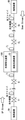
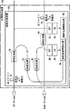
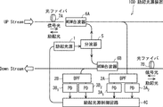
- FIG. 1 is a block configuration diagram showing the configuration of the excitation light source device of this embodiment. Note that the excitation light source device 10 shown in FIG.
- An excitation light source device 10 shown in FIG. 1 includes an excitation light source 1, two band pass filters (BPF) 2A and 2B, two photo detectors (PD) 3A and 3B, and an excitation light source. It includes at least a control circuit 4, a duplexer 5, and two WDM (Wavelength Division Multiplexing) multiplexers 6A and 6B.
- the excitation light source device 10 outputs Raman excitation light to the optical fiber 7A and the optical fiber 7B in order to amplify the WDM signal light (main signal) transmitted through the optical fiber.
- the optical fiber 7A is an optical fiber that transmits WDM signal light in the upstream direction (UP: Up Stream).
- the optical fiber 7B is an optical fiber that transmits a WDM signal in the down direction (DW: Down Stream).
- DW Down Stream
- the circuit unit related to the gain equalization function that compensates for the deviation of the gain wavelength characteristic of the input WDM signal light, which is the original function of the gain equalization apparatus 100, is the same as the conventional technique. Since it does not matter, the description here is omitted.
- the pumping light source 1 is a light source that outputs pumping light having a wavelength slightly shorter than pumping light for Raman amplification, that is, WDM signal light (main signal).
- the two band-pass filters 2A and 2B control the pumping light source 1 from the WDM signal light transmitted through the upstream (UP) optical fiber 7A and the downstream (DW) optical fiber 7B, respectively. It is a filter that extracts signal light.
- the two photodetectors 3A and 3B are detectors that output control signals obtained by detecting the control signal light extracted by the two band-pass filters 2A and 2B, respectively, and converting them into electrical signals.
- the excitation light source control circuit 4 is a control circuit that controls the excitation light source 1 based on control signals from the two photodetectors 3A and 3B.
- the demultiplexer 5 is a circuit that demultiplexes the excitation light output from the excitation light source 1 into two excitation lights, that is, upstream (UP) excitation light and downstream (DW) excitation light.
- the two WDM multiplexers 6A and 6B respectively include an upstream (UP) WDM signal light (main signal), an upstream (UP) pumping light, and a downstream (DW) WDM signal light (main signal). ) And pumping light for the downstream direction (DW).
- the WDM multiplexer 6A is a circuit that multiplexes the upstream (UP) WDM signal light (main signal) and the upstream (UP) excitation light so as to be in opposite directions.
- the WDM multiplexer 6B is a circuit that multiplexes the downstream (DW) WDM signal light (main signal) and the downstream (DW) pumping light in opposite directions.
- the Raman amplification pumping light is opposite to the WDM signal light (main signal) in that the signal having a wavelength slightly longer than the wavelength of the pumping light from the pumping light source 1 is Raman amplified. This shows a case where the backward excitation method is used.
- the pumping light is output from the WDM multiplexer 6A to the optical fiber 7A in the upstream direction (UP) in the direction opposite to the WDM signal light (main signal), thereby causing the Raman amplification effect in the optical fiber 7A.
- WDM signal light (main signal) is amplified.
- the pumping light is output from the WDM multiplexer 6B to the optical fiber 7B in the downstream direction (DW) in the direction opposite to the WDM signal light (main signal), thereby the Raman amplification effect in the optical fiber 7B.
- the WDM signal light (main signal) is amplified.
- the gain equalization apparatus 100 including the pumping light source device 10 is installed after the optical fiber 7A, 7B.
- the input power of the connected optical repeater can be increased.
- the gain tilt amount of the WDM signal light (main signal) in each of the upstream direction (UP) and the downstream direction (DW) can be adjusted.
- FIG. 2 is a system configuration diagram illustrating an example of an optical fiber transmission relay system configured using the gain equalization apparatus 100 including the pumping light source device 10 illustrated in FIG. 1 as one of the components.
- the optical fiber transmission relay system shown in FIG. 2 can be operated as a relay system of an optical submarine cable system, for example.
- a gain equalization apparatus 100 including a pumping light source device 10 including a pumping light source for Raman amplification is disposed in a submarine relay section.
- Raman amplification is performed by the gain equalization apparatus 100 including the pumping light source device 10 with respect to the loss fluctuation on the transmission path of the optical submarine cable by remote control from the land terminal devices 8A and 8B.
- the optical fiber transmission repeater system for optical transmission over a long distance between the terminal equipment 8A and the terminal equipment 8B includes optical fibers 71,..., 7i, 7j,. , 7n, optical repeaters 91, ... 9i, 9j, ..., 9n are arranged in multiple stages.
- One or a plurality of gain equalization apparatuses 100 including the pumping light source apparatus 10 shown in FIG. 1 may be arranged as necessary. For example, in the example of FIG. 2, only one is provided between the optical fibers 7i and 7j. An example of connection is shown.
- the excitation light source device 10 is installed in the gain equalization device 100 that compensates for the deviation of the gain wavelength characteristic of the input WDM signal light as described above.
- the excitation light source device 10 may be installed in a dynamic gain equalizer (AGEQ: Active Gain Equalizer) capable of dynamically compensating for the deviation of the gain wavelength characteristic.
- AGEQ Active Gain Equalizer
- the excitation light source device 10 may be installed in an optical repeater that amplifies and repeats input WDM signal light.
- the pump light source device 10 does not coexist with the gain equalization function and the amplification relay function, and is used for independent pump light output having only the pump light output function, between the gain equalization device and the optical repeater. It may be installed independently at an appropriate place.
- the gain equalization apparatus 100 incorporating the pumping light source device 10 shown in FIG. 1 is introduced, the gain of the WDM signal light (main signal) is equalized and the gain of FIG. Compensation and adjustment of the gain tilt can be performed by using the excitation light source 1 for Raman amplification.
- the excitation light source 1 of the excitation light source device 10 is not in operation.
- the loss in the optical fiber relay section (span) increases due to aging degradation of the optical fiber, repair of the optical fiber, etc.
- a gain tilt occurs.
- a control signal for operating the excitation light source 1 of the excitation light source device 10 is transmitted toward the excitation light source device 10 in the gain equalization device 100.
- the excitation light source control circuit 4 of the excitation light source device 10 controls the excitation light source 1 based on the control signal to output the excitation light for Raman amplification.
- the pumping light from the pumping light source 1 is multiplexed with the upstream and downstream WDM signal light (main signal) in each of the WDM multiplexers 6A and 6B, thereby generating Raman amplification in the optical fibers 7A and 7B. . Therefore, the gain tilt amount can be adjusted by increasing the input power of the optical repeater connected to the next stage via the optical fibers 7A and 7B.
- Raman amplification means that when strong excitation light is incident on an optical fiber, stimulated emission based on Raman scattering occurs, and amplification is performed in a wavelength region longer by about 100 nm than the wavelength of excitation light. It is a phenomenon that is effective.
- FIG. 3 is a characteristic diagram for explaining the Raman amplification effect caused by the strong excitation light entering the optical fiber.
- FIG. 3 shows the wavelength on the horizontal axis and the optical power / Raman gain on the vertical axis.
- the Raman gain of the WDM signal light main signal
- the Raman gain of the WDM signal light main signal
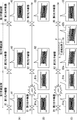
- FIG. 4 is an explanatory diagram for explaining the effect when pumping light from the pumping light source device 10 is inserted into an optical fiber that transmits WDM signal light.
- FIG. 4 schematically shows the waveform of the WDM signal light output from the optical repeater in each of the first, second, and third repeating sections in the optical fiber.
- FIG. 4 shows the waveform state of the WDM signal light immediately after the start of operation of the optical fiber transmission relay system. Immediately after the start of operation, there is no gain deviation of the optical fiber. Therefore, the WDM signal light output from each of the first optical repeater 91, the second optical repeater 92, and the third optical repeater 93 for each of the first, second, and third repeater sections, As shown by signal waveforms A1, A2, and A3, the waveforms are in a substantially uniform gain state.
- FIG. 4B shows a WDM in a state where the operation of the optical fiber transmission relay system has progressed and the loss (LOSS) in the first relay section of the optical fiber has increased due to aging of the optical fiber, repair of the optical fiber, or the like.
- the waveform state of the signal light is shown.
- the WDM signal light output from the first optical repeater 91 for the first repeater section and transmitted through the first repeater section is affected by an increase in loss (LOSS) as shown in the signal waveform B1a to the signal waveform B1b.
- the power is reduced and input to the second optical repeater 92 for the second repeater section in the next stage.
- the second optical repeater 92 for the second repeater section inherently increases the gain of the optical amplifier in the second optical repeater 92 in order to compensate for the shortage of input power due to loss (LOSS).
- the WDM signal light is amplified with a value higher than the set value.
- the WDM signal light output from the second optical repeater 92 has a state in which the entire signal band has a negative gain slope (a state in which the right side is lowered) as shown in the signal waveform B2.
- WDM signal light having a gain gradient is transmitted through the second relay section and input to the third optical repeater 93 for the third relay section in the next stage.
- the WDM signal light output from the third optical repeater 93 for the third relay section also remains in a gain-tilt state as indicated by the signal waveform B3. Therefore, the WDM signal light is transmitted in the state where the gain is tilted as shown in the signal waveform B3 also in the third relay section. Since the gain-tilted WDM signal light has a gain deviation, the transmission WDM signal light is subject to an increase in optical SNR degradation and non-linear degradation, resulting in degradation of transmission characteristics. .
- FIG. 4C shows the waveform state of the WDM signal light when the excitation light source device 10 is arranged at the point P of the second relay section.
- a control signal is transmitted to the excitation light source device 10 as described above.
- the excitation light source 1 is controlled by the excitation light source control circuit 4 to output excitation light for Raman amplification.
- the excitation for Raman amplification output from the excitation light source 1 of the excitation light source device 10 at the point P in the second relay section is amplified by the Raman amplification effect in the optical fiber.
- the input power to the third optical repeater 93 for the third repeater section at the next stage is set to the original set value as shown in the signal waveform C2b in order to compensate for the loss. Amplified to a slightly higher value.
- the third optical repeater 93 for the third repeater section adjusts the gain of the optical amplifier in the third optical repeater 93 to the original set value in order to adjust the output power to a preset output.
- the WDM signal light is amplified with a lower value.
- the entire signal band has a positive gain slope opposite to the output from the second optical repeater 92 (upwardly rising). Is amplified.
- the WDM signal light output from the third optical repeater 93 can be returned to a flat state without gain tilt and output. Therefore, since the gain deviation can be improved, it is possible to ensure the steadiness of good transmission characteristics.
- the input power to the optical repeater at the next stage is appropriately controlled by the Raman amplification effect of the pumping light source device 10 with respect to the loss variation of the transmission line. can do. Therefore, it is possible to suppress the subsequent occurrence of gain tilt of the optical repeater, and it is possible to steadily secure good transmission characteristics even after system operation.
- Raman amplification differs depending on the positional relationship between the point where the loss (LOSS) occurs and the point P where the gain equalization apparatus 100 including the excitation light source 1 is installed.
- the point where the gain equalization apparatus 100 including the excitation light source 1 is installed is the same first relay section as the point where the loss (LOSS) occurs
- a loss (LOSS) occurs between the second optical repeater 92 for the second repeater section in the next stage.
- the input power to the device 92 can be set to the same state as in FIG.
- the output from the second optical repeater 92 can be set to the same state as in FIG. Accordingly, the influence on the third optical repeater for the subsequent third repeater section can be eliminated.
- the pumping light source device 10 shown in FIG. 1 in the case of a circuit configuration in which pumping light for Raman amplification is propagated in the direction opposite to the WDM signal light (main signal) to be amplified (that is, backward pumping Raman amplification is performed).
- the device configuration may be such that the pump light for Raman amplification and the WDM signal light (main signal) to be amplified propagate in the same direction (that is, forward pump Raman amplification is performed). Needless to say.
- the pumping light source that outputs the pumping light for Raman amplification is not limited to one as in the example shown in FIG. 1, and a configuration in which a plurality of pumping light sources are installed is also possible.
- FIG. 5 is a block diagram showing the configuration of the excitation light source device of the present embodiment.
- An excitation light source device 10A shown in FIG. 5 is installed in the gain equalization apparatus 100 as in FIG. 1, but unlike the excitation light source device 10 of FIG. 1, an excitation light source that outputs excitation light for Raman amplification. Is installed (N: an integer of 2 or more).
- the excitation light source device 10A shown in FIG. 5 includes N excitation light sources 11,..., 1N that output excitation light of different wavelengths, instead of the single excitation light source 1 in the excitation light source device 10 of FIG. I have.
- the excitation light source device 10A shown in FIG. 5 includes an excitation light combiner 8 for combining the excitation light output from each of the N excitation light sources 11,. This configuration is added to the excitation light source device 10 of FIG.
- the excitation light source control circuit 4 is configured to be able to control each of the N excitation light sources 11,..., 1N separately based on control signals from the two photodetectors 3A, 3B.
- the frequency shift amount (ie, wavelength shift amount) of excitation light energy when stimulated Raman scattering is caused depends on the material of the optical fiber that is a medium in Raman amplification. Therefore, by adopting the apparatus configuration of the excitation light source apparatus 10A of FIG. 5 and installing a plurality of excitation light sources 11 that output excitation light having a wavelength, adjustment of an appropriate gain inclination with respect to the WDM signal light (main signal); Level correction of only a part of the wavelength band is possible. That is, a plurality of excitation light sources 11,..., 1N that output excitation light of different wavelengths are installed in advance, and each excitation light source 11,..., 1N is controlled separately via the excitation light source control circuit 4.
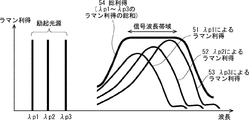
- FIG. 6 is a characteristic diagram for explaining the principle of the Raman amplification effect in the excitation light source device 10A of FIG. 5, in which the horizontal axis indicates the wavelength and the vertical axis indicates the amount of optical power / Raman gain.
- each of the three excitation light sources outputs excitation light having wavelengths that become longer in the order of wavelengths ⁇ p1, ⁇ p2, and ⁇ p3.
- the Raman gain spectrum has a Raman gain spectrum, a Raman gain 52, and a Raman gain 53 of about 100 nm longer than the respective excitation light in accordance with the wavelengths ⁇ p1, ⁇ p2, and ⁇ p3.
- An amplification effect occurs. Therefore, an amplification amount relating to the signal wavelength band as shown by a bold curve in FIG. 6 is obtained as a total gain 54 (that is, a sum of Raman gains of the respective wavelengths ⁇ p1, ⁇ p2, and ⁇ p3) by the three-wave pump light. It is done.
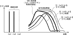
- FIG. 7 is a characteristic diagram showing a control example of the Raman amplification effect in the excitation light source device 10A of FIG. 5, and shows a case where Raman amplification is performed with respect to the signal wavelength band on the short wavelength side other than the long wavelength side as an example.
- the excitation light having the longest wavelength ⁇ p3 is not output, and the excitation light having the two wavelengths ⁇ p1 and ⁇ p2 on the short wave side is output.
- the total gain 54A that is, the sum of the Raman gains of the respective pump lights having the wavelengths ⁇ p1 and ⁇ p2 due to the two pump lights on the short wave side
- the amount of amplification on the short wave side increases and is shown by a bold curve.
- Amplification amount for a wide signal wavelength band can be obtained.
- by independently selecting and controlling the plurality of pumping light sources 11,..., 1N that output pumping light having different wavelengths it becomes possible to finely adjust the Raman gain for each signal wavelength band. More accurate gain adjustment with respect to the gain tilt becomes possible.
- FIG. 8 is a block configuration diagram showing the configuration of the excitation light source device according to the present embodiment.
- the excitation light source device 10B shown in FIG. 8 is installed in the gain equalization device 100, as in the case of FIG.
- the excitation light source device 10 ⁇ / b> B sets the power level of the excitation light by control from the excitation light source control circuit 4 at the subsequent stage of the excitation light source 1 that outputs excitation light for Raman amplification.
- a variable attenuator 9 that is variably attenuated and output to the duplexer 5 is additionally provided.
- FIG. 9 is a block configuration diagram showing a configuration of the excitation light source device according to the present embodiment.
- the excitation light source device 10C shown in FIG. 9 is installed in the gain equalization device 100 as in the case of FIG. Unlike the excitation light source device 10 shown in FIG. 1, the excitation light source device 10C shown in FIG. 9 shares the excitation light source 1 that outputs the excitation light for Raman amplification in the upstream direction (UP) and the downstream direction (DW). Absent. That is, the excitation light source device 10C shown in FIG. 9 includes separate excitation light sources that are independent in the upstream direction (UP) and the downstream direction (DW), respectively.
- the pumping light source device 10C shown in FIG. 9 changes the pumping light source 1 in the pumping light source device 10 of FIG. 1 and makes pumping independent in the upstream direction (UP) and the downstream direction (DW).
- the light source 1A and the excitation light source 1B two excitation light sources are provided.
- the duplexer 5 in the excitation light source device 10 of FIG. 1 is omitted.
- the excitation light source device 10C shown in FIG. 9 converts the excitation light output from each of the excitation light source 1A and the excitation light source 1B into the WDM multiplexer 6A and the WDM multiplexer 6B in the upstream direction (UP) and the downstream direction (DW). It is the structure which connected directly to.
- 10C of excitation light source apparatuses shown in FIG. 9 are provided with the structure which can control each excitation light source 1A and excitation light source 1B of an up direction (UP) and a down direction (DW) independently. That is, the pumping light source device 10C shown in FIG. 9 uses the pumping light source control circuit 4 in the case of FIG. 1 as the pumping light source control circuit 4A for the upstream direction (UP) and the pumping light source control circuit for the downstream direction (DW), respectively. The configuration is divided into 4B.
- the excitation light source 1A and the excitation light source 1B in the upstream direction (UP) and the downstream direction (DW) can be controlled independently. Therefore, the amount of Raman amplification with respect to the WDM signal light (main signal) can be finely adjusted in the upstream direction (UP) and the downstream direction (DW), and more accurate gain adjustment with respect to the gain inclination becomes possible. . Furthermore, it is possible to set ON / OFF of the excitation light separately in the upstream direction (UP) and the downstream direction (DW).
- the insertion positions on the optical fiber of the pumping light source for Raman amplification in the optical fiber transmission relay system include the pumping light source devices 10, 10A, 10B, and 10C in any case.
- GEQ Gain Equalizer
- FIG. 10 is an explanatory diagram showing an example of a relay section in which an excitation light source for Raman amplification is inserted on an optical fiber in an optical fiber relay transmission system.
- pumping light source devices 10, 10A, 10B, and 10C each including a pumping light source for Raman amplification all have a gain equalization circuit 101A for uplink (UP) and a downlink (DW). It is built in the gain equalization apparatus 100 provided with the gain equalization circuit 101B. Therefore, the pump light source for Raman amplification is inserted into a relay section on the optical fiber in which the gain equalization circuit 100 is inserted (in FIG. 10, a relay section between the optical repeater 9i and the optical repeater 9j). Will be.
- FIG. 10 a relay section between the optical repeater 9i and the optical repeater 9j.
- FIG. 10 illustrates the case of the excitation light source device 10 shown in FIG. 1 as the circuit configuration of the excitation light source device built in the gain equalization apparatus 100.
- the excitation light source devices 10A, 10B, and 10C of FIGS. 5, 8, and 9 are used as the excitation light source device built in the gain equalization apparatus 100. Even if there is, it is the same.
- the excitation light source devices 10, 10A, 10B, and 10C may be installed in a form incorporated in the optical repeater instead of the gain equalization device 100.
- the insertion position on the optical fiber of the excitation light source for Raman amplification in the optical fiber transmission repeater system can be changed.
- it is a relay section where the optical repeater 90 is installed. That is, in FIG. 11, the insertion position on the optical fiber of the pump light source for Raman amplification is an optical repeater span in which the optical repeater 90 incorporating the pump light source devices 10, 10A, 10B, and 10C is installed. Yes.
- FIG. 11 is an explanatory diagram showing an example different from FIG. 10 of the relay section where the pump light source for Raman amplification is inserted on the optical fiber in the optical fiber relay transmission system, and is the same as the position where the optical repeater is inserted The case where it has inserted in the position is shown.
- pumping light source apparatuses 10, 10A, 10B, and 10C each including a pumping light source for Raman amplification all have an optical amplifier 91A for uplink (UP) and light for downlink (DW). It is built in an optical repeater 90 having an amplifier 91B. Therefore, the pumping light source for Raman amplification is inserted into a relay section on the optical fiber into which the optical repeater 90 is inserted (in FIG.
- FIG. 11 the relay section between the optical repeater 9k and the optical repeater 9l). Will be. 11 also illustrates the case of the pumping light source device 10 shown in FIG. 1 as the circuit configuration of the pumping light source device built in the optical repeater 90, but FIG. 5, FIG. 8, and FIG. The same applies to the nine excitation light source devices 10A, 10B, and 10C.
- the Raman amplification excitation light source 1 passes through the optical fiber.
- the excitation light source control circuit 4 (, 4A, 4B) is controlled based on the transmitted control information.
- the excitation light source device 10 (10A, 10B, and 10C) is installed at the end in the optical fiber transmission relay system. It is possible to remotely control from a terminal device.
- FIG. 12 is an explanatory diagram for explaining the operating principle of remotely controlling the pumping light source device inserted on the optical fiber from the terminal device in the optical fiber transmission relay system.
- the system configuration is the same as the configuration described above in FIG. The same.
- Such remote control from the terminal equipment is indispensable particularly when the optical fiber transmission relay system is operated as a relay system of an optical submarine cable system. That is, in the case of a relay system of an optical submarine cable system, as shown in FIG. 12, a pumping light source device 10 is built in a relay section between an optical repeater 9i and an optical repeater 9j laid on the seabed. Thus, the gain equalization apparatus 100 is installed.
- the gain equalization apparatus 100 is a dynamic gain equalization apparatus (AGEQ) that can dynamically compensate for a deviation in gain wavelength characteristics. Therefore, it is indispensable to remotely control the pumping light source device 10 on the seabed from a terminal device installed on land, for example, a terminal device 8B installed in the upstream direction (UP) of the pumping light source device 10. Toward.
- AGEQ dynamic gain equalization apparatus
- the terminal device 8B constantly monitors the transmission quality of the WDM signal light transmitted from the upstream (UP) optical fiber.
- the terminal device 8B detects that the degradation of transmission quality due to the increase of the gain tilt in the optical fiber transmission line as a reception spectrum occurs exceeding a predetermined threshold (step S1), the terminal station device 8B cancels the gain tilt.
- the power level of the pumping light for Raman amplification required for the calculation is calculated.
- the terminal station device 8B When the terminal station device 8B calculates the power level of the pumping light, the terminal device 8B generates a command signal (control signal) for controlling the pumping light source including information related to the power level, and transmits the command signal to the corresponding pumping light source device 10 in the down direction ( DW) is transmitted through the optical fiber (step S2).
- the command signal (control signal) transmitted from the terminal device 8B is delivered to the excitation light source control circuit 4 via the bandpass filter 2B and the photodetector 3B as described above.
- the excitation light source control circuit 4 activates the excitation light source 1 based on the transmitted command signal (control signal), and outputs the excitation light for Raman amplification at a specified power level.
- the gain tilt amount can be adjusted by increasing the input power of the optical repeater 9i connected to the next stage via the optical fiber 7i.
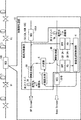
- FIG. 13 is a block configuration diagram showing the configuration of the excitation light source device according to the present embodiment, and shows an example configuration for automatically controlling the excitation light source.
- the pumping light source device 10D shown in FIG. 13 is shown as an independent device, it is configured to be built in the gain equalization device 100 or the optical repeater 90 as described in FIGS. But of course.
- the excitation light source device 10D shown in FIG. 13 is changed from the configuration in which the upstream (UP) photodetector 3A and the downstream (DW) photodetector 3B are installed one by one in the excitation light source device 10 of FIG. Yes. That is, the excitation light source device 10D shown in FIG. 13 has a configuration in which two photodetectors 3A 1 and 3A 2 and two photodetectors 3B 1 and 3B 2 are installed. Further, in the excitation light source device 10D shown in FIG. 13, the configuration related to the excitation light source control circuit 4 is changed from the excitation light source device 10 of FIG. That is, the excitation light source device 10D shown in FIG.
- the 13 includes an excitation light source control circuit 4C having a function of automatically controlling the excitation light source 1.
- the excitation light source control circuit 4C performs excitation based on the comparison result of both outputs of the upstream (UP) photodetectors 3A 1 and 3A 2 and the comparison result of both outputs of the downstream (DW) photodetectors 3B 1 and 3B 2.
- the light source 1 is automatically controlled.
- both the upstream (UP) photodetectors 3A 1 and 3A 2 detect and detect the power levels of the shortest wave side and the longest wave side of the upstream (UP) WDM signal light (main signal). The result is output to the excitation light source control circuit 4C.
- both the downstream (DW) photodetectors 3B 1 and 3B 2 detect and detect the power levels of the shortest wave side and the longest wave side of the WDM signal light (main signal) in the downstream direction (UP). The result is output to the excitation light source control circuit 4C.
- the excitation light source control circuit 4C monitors and compares changes in the power level between the shortest wave side and the longest wave side of the WDM signal light (main signal) in the upstream direction (UP) and the downstream direction (DW).
- the level deviation (tilt increase) of the WDM signal light (main signal) is generated based on the comparison result of the change of the power level, and the gain tilt of the WDM signal light (main signal) is generated. Detect whether or not.
- the excitation light source control circuit 4C detects that the gain inclination of the WDM signal light (main signal) is generated, the excitation light source control circuit 4C calculates the power level of the Raman amplification excitation light necessary to eliminate the gain inclination. Then, the pumping light source 1 is activated to output pumping light of the instructed power level.
- the gain tilt amount can be automatically adjusted by increasing the input power of the optical repeater connected to the next stage through the optical fiber. Therefore, even when an optical fiber is repaired or a loss (LOSS) increases due to secular change, the gain slope can be automatically adjusted and can be easily dealt with.
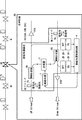
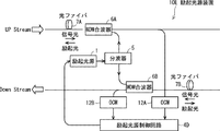
- FIG. 14 is a block configuration diagram showing the configuration of the excitation light source device according to the present embodiment, and shows an example of a configuration different from the case of FIG. 13 as a configuration example for automatically controlling the excitation light source.
- the pumping light source device 10E shown in FIG. 14 is shown as an independent device. However, as described in FIGS. 10 and 11, the pumping light source device 10E is configured to be built in the gain equalizing device 100 or the optical repeater 90. But of course.
- the excitation light source device 10E shown in FIG. 14 has a level variation (tilt increase) of the WDM signal light (main signal) in each of the upstream direction (UP) and the downstream direction (DW).
- Optical channel monitors (OCM) 12A and 12B having a detection function are provided. Further, the excitation light source device 10E shown in FIG.
- the pumping light source control circuit 4D receives the notification that the level variation (tilt increase) of the WDM signal light (main signal) is generated as a detection result of the optical channel monitors 12A and 12B, and thereby the WDM signal light (main signal). ) Can be detected. Therefore, the excitation light source control circuit 4D calculates the power level of the Raman amplification excitation light necessary to eliminate the gain gradient, activates the excitation light source 1, and outputs the instructed excitation light at the power level. Output. As a result, the gain tilt amount can be automatically adjusted by increasing the input power of the optical repeater connected to the next stage through the optical fiber. Therefore, it is possible to automatically adjust the gain slope even when the optical fiber is repaired or the loss (LOSS) due to aging increases, and can be easily dealt with.
- the excitation light source control circuit 4D calculates the power level of the Raman amplification excitation light necessary to eliminate the gain gradient, activates the excitation light source 1, and outputs the instructed excitation light at the power level. Output
- the excitation light source control circuit 4D determines whether or not a gain tilt of the WDM signal light (main signal) has occurred based on the information on the optical spectrum deviation of the WDM signal light detected by the alternative means. You can do it.
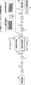
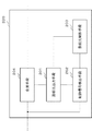
- FIG. 15 is a block configuration diagram showing the configuration of the excitation light source device 200 of the present embodiment.
- the pumping light source device 200 of the present embodiment is installed in an optical fiber relay section in an optical fiber transmission relay system that transmits wavelength-multiplexed WDM signal light, and is used for Raman amplification when a gain tilt of the WDM signal light occurs. It is a device that outputs excitation light.
- the excitation light source device 200 of the present embodiment includes excitation light output means 201, control signal detection means 202, excitation light control means 203, and multiplexing means 204.
- Excitation light output means 201 outputs excitation light for Raman amplification.
- the control signal detection unit 202 detects the control signal of the pumping light output unit 201 from the WDM signal light transmitted through the upstream and downstream optical fibers.
- the excitation light control unit 203 controls the excitation light output unit 201 based on the control signal.
- the multiplexing unit 204 combines the pumping light with the WDM signal light in the upstream direction and the downstream direction, and outputs them to the upstream optical fiber and the downstream optical fiber, respectively.
- the control signal detection unit 202 detects a control signal from the WDM signal light
- the excitation light control unit 203 outputs the excitation light output from the excitation light output unit 201 based on the detected control signal.
- the excitation light source device 200 combines the excitation light with the WDM signal light in the upstream direction and the downstream direction in the multiplexing unit 204 and outputs the multiplexed light to the upstream optical fiber and the downstream optical fiber, respectively. Therefore, by using the pumping light source device 200 of the present embodiment, the start of pumping light output can be controlled by sending a control signal through the optical fiber. Therefore, when a gain tilt occurs due to aging degradation of the optical fiber, etc. The gain equalization can be performed to ensure good optical transmission characteristics.
- the gain equalization device built in the pumping light source device, or the optical repeater built in the pumping light source device is not limited to one. . That is, the pumping light source device according to each embodiment, the gain equalization device built in the pumping light source device, or the optical repeater built in the pumping light source device is installed in a plurality of units as necessary in the optical transmission relay system. It is also possible.
- the pumping light source device, gain equalization device, and optical repeater of each of the above embodiments can also be configured as follows.
- the excitation light source device is In an optical fiber transmission repeater system that transmits wavelength-division multiplexed WDM (Wavelength Division Multiplexing) signal light, it is installed in the optical fiber relay section, and when the gain inclination of the WDM signal light occurs, the pump light for Raman amplification is output.
- WDM wavelength-division multiplexed
- Raman amplification the pump light for Raman amplification is output.
- An excitation light source device An excitation light source that outputs excitation light for Raman amplification; Band-pass filters for upstream and downstream, respectively, for extracting control signal light for controlling the pumping light source from the WDM signal light transmitted through the optical fibers in the upstream and downstream directions; An upstream and downstream photodetector that detects the control signal light output from each of the upstream and downstream bandpass filters, converts the light into an electrical signal, and outputs the electrical signal as a control signal; , An excitation light source control circuit for controlling the excitation light source based on the control signals respectively output from the upstream and downstream photodetectors; A demultiplexer for demultiplexing the pumping light output from the pumping light source into pumping light for upstream and downstream directions; The upstream pumping light and the upstream WDM signal light demultiplexed by the duplexer, and the downstream pumping light and the downstream WDM signal light are combined. And two multiplexers respectively outputting to the upstream optical fiber and the downstream optical fiber.
- the gain equalization apparatus is arranged in a repeater section on an optical fiber as a component of an optical fiber transmission repeater system that transmits wavelength-division multiplexed WDM (Wavelength Division Multiplexing) signal light.
- a gain equalization apparatus having a gain equalization function that compensates for a deviation in gain wavelength characteristics of the WDM signal light transmitted above includes the excitation light source device described in (1) above. .
- the optical repeater according to the present embodiment is disposed in a repeating section on an optical fiber as a component of an optical fiber transmission repeating system that transmits wavelength-division multiplexed WDM (Wavelength Division Multiplexing) signal light.
- An optical repeater having a function of amplifying and relaying the WDM signal light transmitted to the terminal includes the pumping light source device according to (1).
- a pumping light source device for Raman amplification is installed in a relay section of an optical fiber (optical transmission line), and the optical fiber It starts when the loss of the optical transmission line changes due to aging or repairs, and the gain slope of the WDM signal light occurs.
- the Raman amplification effect by the pumping light from the pumping light source Since the input power of the WDM signal light to the optical repeater is appropriately controlled, it is possible to suppress the occurrence of a gain gradient in the optical repeaters in the subsequent stages and to ensure good optical transmission characteristics.
- Appendix 1 In an optical fiber transmission repeater system that transmits wavelength-division multiplexed WDM (Wavelength Division Multiplexing) signal light, it is installed in the optical fiber relay section, and when the gain inclination of the WDM signal light occurs, the pump light for Raman amplification is output.
- WDM Wavelength Division Multiplexing
- An excitation light source device Excitation light output means for outputting excitation light for Raman amplification;
- Control signal detecting means for detecting a control signal of the pumping light output means from the WDM signal light transmitted through the optical fibers in the upstream and downstream directions;
- Excitation light control means for controlling the excitation light output means based on the control signal;
- a pumping light source device comprising: a multiplexing unit configured to combine the pumping light with the WDM signal light in the upstream direction and the downstream direction and output the multiplexed light to the optical fiber in the upstream direction and the optical fiber in the downstream direction, respectively.
- the excitation light output means has means for outputting a plurality of the excitation lights each having a different wavelength
- the multiplexing unit combines the pumping light, which is output from the pumping light output unit and combined with a plurality of pumping lights having different wavelengths, into the WDM signal light in the upstream direction and the downstream direction, respectively.
- the pumping light source device according to appendix 1, wherein the pumping light source device outputs to an upstream optical fiber and a downstream optical fiber, respectively.
- (Appendix 3) Variable attenuation means for attenuating and outputting the power level of the excitation light output from the excitation light output means;
- the multiplexing unit combines the pump light attenuated by the attenuation unit with the WDM signal light in the upstream direction and the downstream direction, and outputs the multiplexed light to the upstream optical fiber and the downstream optical fiber, respectively.
- the excitation light source device according to appendix 1 or 2, characterized in that.
- (Appendix 4) Further comprising demultiplexing means for demultiplexing the excitation light output by the excitation light output means into the excitation light for the upstream direction and the downstream direction,
- the multiplexing means multiplexes the pumping light for the upstream direction demultiplexed by the branching means and the WDM signal light for the upstream direction and outputs the multiplexed light to the optical fiber in the downstream direction, and the pumping light for the downstream direction 4.
- the pumping light source device according to any one of appendices 1 to 3, wherein the WDM signal light in the downstream direction is combined and output to the optical fiber in the downstream direction.
- the excitation light output means includes an upstream excitation light source and a downstream excitation light source,
- the excitation light control unit according to any one of appendices 1 to 3, wherein the excitation light control unit separately controls the upstream excitation light source and the downstream excitation light source based on the control signal.
- Light source device includes an upstream excitation light source and a downstream excitation light source.
- the control signal detection means extracts the control signal light for controlling the pumping light output means from the upstream and downstream optical fibers from the WDM signal light transmitted through the upstream and downstream optical fibers, respectively.
- a signal extracting means 6.
- the excitation light source device according to any one of appendices 1 to 5, wherein the control signal detection unit converts the control signal light into an electrical signal and outputs the electrical signal as the control signal.
- the control signal detection means includes power levels of the shortest wave side and the longest wave side of the main signal of the WDM signal light in the upstream direction, and a shortest wave side and a longest wave side of the main signal of the WDM signal light in the down direction. Detects the power level of each
- the pumping light control means compares the power levels of the shortest wave side and the longest wave side in the upstream WDM signal light and the downstream WDM signal light, respectively, and the upstream or downstream WDM signal When it is detected that a power level deviation has occurred in at least one main signal of light, the power level of the pumping light required to eliminate the power level deviation is calculated, and the pumping light output means 6.
- the pumping light source device according to any one of appendices 1 to 5, wherein the pumping light output is controlled so as to output the pumping light of the power level calculated from the above.
- the control signal detecting means further comprises means for detecting a fluctuation in the power level of the main signal of the WDM signal light transmitted through the optical fibers in the upstream direction and the downstream direction,
- the excitation light control means detects the occurrence of the gain inclination of the main signal based on the detection result of the fluctuation of the main signal power level, and the excitation light necessary for eliminating the gain inclination is detected.
- the excitation light source device according to any one of appendices 1 to 5, wherein the excitation light output unit is controlled to calculate a power level and output the excitation light of the power level calculated from the excitation light output unit. .
- Appendix 10 As a component of an optical fiber transmission repeater system for transmitting wavelength-division multiplexed WDM (Wavelength Division Multiplexing) signal light, gain wavelength characteristics of the WDM signal light that is disposed in the repeater section on the optical fiber and transmitted on the optical fiber 10.
- a gain equalization circuit having a gain equalization function for compensating for a deviation of the gain, wherein the excitation light source device according to any one of appendices 1 to 9 is incorporated.
- Appendix 11 As a component of an optical fiber transmission relay system that transmits wavelength-division multiplexed WDM (Wavelength Division Multiplexing) signal light, it is arranged in a relay section on the optical fiber and amplifies and relays the WDM signal light transmitted on the optical fiber
- a gain equalization circuit comprising a pumping light source device according to any one of appendices 1 to 9 in an optical repeater having a function.
- a gain equalization method when a gain tilt of the WDM signal light occurs, Detecting a control signal of a pumping light source that outputs pumping light for Raman amplification from the WDM signal light transmitted through the optical fiber in the upstream and downstream directions; Controlling the excitation light source based on the control signal; Outputting the excitation light for Raman amplification from the excitation light source;
- a gain equalization method comprising: combining the pump light with the WDM signal light in the upstream direction and the downstream direction and outputting the multiplexed light to the optical fiber in the upstream direction and the optical fiber in the downstream direction, respectively.
- the excitation light is output from each of the plurality of excitation light sources having different wavelengths of the excitation light to be output,
- the pumping light combined with the pumping light output from each of the plurality of pumping light sources is combined with the upstream and downstream WDM signal light, respectively, and the upstream optical fiber and the downstream light are combined.
- Item 13 The gain equalization method according to appendix 12, wherein the gain is output to each fiber.
- the excitation light output from the excitation light source is demultiplexed into the excitation light for the upstream direction and the downstream direction,
- the demultiplexed upstream pumping light and the upstream WDM signal light are combined and output to the optical fiber in the downstream direction, and the downstream pumping light and the downstream WDM signal light are combined.
- the gain equalization method according to any one of appendices 12 to 14, wherein the gain equalization method outputs each to a downstream optical fiber.
- Appendix 17 Extracting control signal light for controlling the pumping light source from the upstream and downstream optical fibers from the WDM signal light transmitted in the upstream and downstream optical fibers, The gain equalization method according to any one of appendices 12 to 16, wherein the control signal light is converted into an electric signal, and the electric signal is output as the control signal.
- Appendix 20 The control signal light transmitted through the optical fiber in each of the upstream and downstream directions is transmitted from the terminal station based on a result of monitoring optical transmission quality performed in the terminal station apparatus constituting the optical fiber transmission relay system. 19.
- Gain equalization apparatus 101A Gain equalization circuit 101B Gain equalization circuit 200
- Excitation light source apparatus 201
- Excitation light output means 202
- Control signal detection means 203
- Excitation light control means 204 Combined means
Landscapes
- Physics & Mathematics (AREA)
- Engineering & Computer Science (AREA)
- Electromagnetism (AREA)
- Computer Networks & Wireless Communication (AREA)
- Signal Processing (AREA)
- Nonlinear Science (AREA)
- Optics & Photonics (AREA)
- General Physics & Mathematics (AREA)
- Microelectronics & Electronic Packaging (AREA)
- Plasma & Fusion (AREA)
- Optical Modulation, Optical Deflection, Nonlinear Optics, Optical Demodulation, Optical Logic Elements (AREA)
- Optical Communication System (AREA)
Abstract
Priority Applications (4)
| Application Number | Priority Date | Filing Date | Title |
|---|---|---|---|
| JP2018509107A JP6773111B2 (ja) | 2016-03-30 | 2017-03-22 | 励起光源装置および利得等化方法 |
| US16/086,335 US11189984B2 (en) | 2016-03-30 | 2017-03-22 | Excitation light source apparatus and gain equalizing method |
| EP17774549.4A EP3438735A4 (fr) | 2016-03-30 | 2017-03-22 | Appareil de source de lumière d'excitation et procédé d'égalisation de gain |
| CN201780019980.1A CN108885382A (zh) | 2016-03-30 | 2017-03-22 | 激发光源设备和增益均衡方法 |
Applications Claiming Priority (2)
| Application Number | Priority Date | Filing Date | Title |
|---|---|---|---|
| JP2016067731 | 2016-03-30 | ||
| JP2016-067731 | 2016-03-30 |
Publications (1)
| Publication Number | Publication Date |
|---|---|
| WO2017170008A1 true WO2017170008A1 (fr) | 2017-10-05 |
Family
ID=59964370
Family Applications (1)
| Application Number | Title | Priority Date | Filing Date |
|---|---|---|---|
| PCT/JP2017/011318 Ceased WO2017170008A1 (fr) | 2016-03-30 | 2017-03-22 | Appareil de source de lumière d'excitation et procédé d'égalisation de gain |
Country Status (5)
| Country | Link |
|---|---|
| US (1) | US11189984B2 (fr) |
| EP (1) | EP3438735A4 (fr) |
| JP (1) | JP6773111B2 (fr) |
| CN (1) | CN108885382A (fr) |
| WO (1) | WO2017170008A1 (fr) |
Cited By (4)
| Publication number | Priority date | Publication date | Assignee | Title |
|---|---|---|---|---|
| CN110945801A (zh) * | 2018-03-09 | 2020-03-31 | 华为技术有限公司 | 光纤放大器及光纤放大器的增益调节方法 |
| JPWO2023105625A1 (fr) * | 2021-12-07 | 2023-06-15 | ||
| JP2023159913A (ja) * | 2022-04-21 | 2023-11-02 | 富士通株式会社 | ラマン増幅装置、ラマン増幅方法、及びラマン増幅システム |
| WO2024176295A1 (fr) * | 2023-02-20 | 2024-08-29 | 日本電信電話株式会社 | Dispositif de relais d'amplification optique, système de transmission optique et procédé de relais d'amplification optique |
Families Citing this family (3)
| Publication number | Priority date | Publication date | Assignee | Title |
|---|---|---|---|---|
| EP3598668A4 (fr) * | 2017-03-17 | 2020-03-18 | Nec Corporation | Système de câble optique sous-marin et dispositif de relais optique sous-marin |
| CN109103741B (zh) * | 2018-09-04 | 2019-11-26 | 武汉光迅科技股份有限公司 | 一种拉曼光纤放大器的增益动态控制方法、装置和系统 |
| JP7172563B2 (ja) * | 2018-12-21 | 2022-11-16 | 富士通株式会社 | 波長変換装置及び励起光切替方法 |
Citations (6)
| Publication number | Priority date | Publication date | Assignee | Title |
|---|---|---|---|---|
| JP2001249369A (ja) * | 2000-03-02 | 2001-09-14 | Nec Corp | 光増幅器とこれを用いた光増幅中継器及び波長多重光伝送装置 |
| JP2002258335A (ja) * | 2001-03-02 | 2002-09-11 | Fujitsu Ltd | ラマン光増幅中継器 |
| JP2003177440A (ja) * | 2001-12-11 | 2003-06-27 | Nec Corp | 光中継装置及びこれを用いた光伝送方式 |
| JP2008052001A (ja) | 2006-08-24 | 2008-03-06 | Fujitsu Ltd | 光通信用の信号光を増幅するためのラマン光増幅器,ラマン光増幅器を備えた光通信システム,およびラマン光増幅器の制御方法 |
| JP2010122548A (ja) | 2008-11-21 | 2010-06-03 | Fujitsu Ltd | 分布ラマン増幅器および光通信システム |
| US20110141552A1 (en) * | 2009-12-14 | 2011-06-16 | Red-C Optical Networks Ltd. | Automatic measurement and gain control of distributed raman amplifiers |
Family Cites Families (15)
| Publication number | Priority date | Publication date | Assignee | Title |
|---|---|---|---|---|
| JP3532759B2 (ja) * | 1998-03-11 | 2004-05-31 | 富士通株式会社 | Wdm通信システムにおける中継装置及び同装置の送信レベル制御方法 |
| JP3527671B2 (ja) * | 1999-04-23 | 2004-05-17 | 富士通株式会社 | ラマン増幅による光伝送パワーの波長特性制御方法、並びに、それを用いた波長多重光通信システムおよび光増幅器 |
| JP2001168799A (ja) * | 1999-12-08 | 2001-06-22 | Nec Corp | 光通信システム及びそれに用いる光中継器 |
| JP2001223646A (ja) | 2000-02-07 | 2001-08-17 | Nec Corp | 光増幅中継器とこれを用いた光伝送装置 |
| WO2002019023A1 (fr) * | 2000-08-30 | 2002-03-07 | Fujitsu Limited | Amplificateur de lumiere utilisant une amplification de raman et procede de commande de l'amplificateur |
| JP4541574B2 (ja) * | 2001-02-07 | 2010-09-08 | 富士通株式会社 | 光中継伝送システムおよび光中継伝送方法 |
| JP3808766B2 (ja) * | 2001-12-21 | 2006-08-16 | 富士通株式会社 | ラマン増幅器および光伝送システム |
| JPWO2003079584A1 (ja) * | 2002-03-19 | 2005-07-21 | 富士通株式会社 | ラマン増幅を用いた光ファイバ伝送のための方法及びシステム |
| JP4122884B2 (ja) | 2002-07-30 | 2008-07-23 | 日本電気株式会社 | 光中継器 |
| JP3934529B2 (ja) * | 2002-10-30 | 2007-06-20 | 富士通株式会社 | 波長多重光通信システム |
| JP4397239B2 (ja) * | 2004-01-15 | 2010-01-13 | 富士通株式会社 | 光伝送システム |
| JP4489522B2 (ja) * | 2004-07-20 | 2010-06-23 | 富士通株式会社 | 波長多重光伝送システム |
| EP1748581A1 (fr) * | 2005-07-26 | 2007-01-31 | Alcatel | Système de transmission optique WDM à l'aide d'amplificateurs Raman comprenant un canal optique de supervision et système de contrôle |
| US8139951B2 (en) * | 2008-06-26 | 2012-03-20 | Igor Samartsev | Fiber-optic long-haul transmission system |
| JP4679651B2 (ja) | 2008-09-19 | 2011-04-27 | 富士通株式会社 | ラマン増幅器およびその制御方法 |
-
2017
- 2017-03-22 WO PCT/JP2017/011318 patent/WO2017170008A1/fr not_active Ceased
- 2017-03-22 EP EP17774549.4A patent/EP3438735A4/fr not_active Withdrawn
- 2017-03-22 US US16/086,335 patent/US11189984B2/en active Active
- 2017-03-22 CN CN201780019980.1A patent/CN108885382A/zh active Pending
- 2017-03-22 JP JP2018509107A patent/JP6773111B2/ja active Active
Patent Citations (6)
| Publication number | Priority date | Publication date | Assignee | Title |
|---|---|---|---|---|
| JP2001249369A (ja) * | 2000-03-02 | 2001-09-14 | Nec Corp | 光増幅器とこれを用いた光増幅中継器及び波長多重光伝送装置 |
| JP2002258335A (ja) * | 2001-03-02 | 2002-09-11 | Fujitsu Ltd | ラマン光増幅中継器 |
| JP2003177440A (ja) * | 2001-12-11 | 2003-06-27 | Nec Corp | 光中継装置及びこれを用いた光伝送方式 |
| JP2008052001A (ja) | 2006-08-24 | 2008-03-06 | Fujitsu Ltd | 光通信用の信号光を増幅するためのラマン光増幅器,ラマン光増幅器を備えた光通信システム,およびラマン光増幅器の制御方法 |
| JP2010122548A (ja) | 2008-11-21 | 2010-06-03 | Fujitsu Ltd | 分布ラマン増幅器および光通信システム |
| US20110141552A1 (en) * | 2009-12-14 | 2011-06-16 | Red-C Optical Networks Ltd. | Automatic measurement and gain control of distributed raman amplifiers |
Non-Patent Citations (1)
| Title |
|---|
| See also references of EP3438735A4 |
Cited By (11)
| Publication number | Priority date | Publication date | Assignee | Title |
|---|---|---|---|---|
| CN110945801A (zh) * | 2018-03-09 | 2020-03-31 | 华为技术有限公司 | 光纤放大器及光纤放大器的增益调节方法 |
| US11128384B2 (en) | 2018-03-09 | 2021-09-21 | Huawei Technologies Co., Ltd. | Fiber amplifier and gain adjustment method for fiber amplifier |
| CN110945801B (zh) * | 2018-03-09 | 2021-11-19 | 华为技术有限公司 | 光纤放大器及光纤放大器的增益调节方法 |
| US11671179B2 (en) | 2018-03-09 | 2023-06-06 | Huawei Technologies Co., Ltd. | Fiber amplifier and gain adjustment method for fiber amplifier |
| JPWO2023105625A1 (fr) * | 2021-12-07 | 2023-06-15 | ||
| WO2023105625A1 (fr) * | 2021-12-07 | 2023-06-15 | 日本電気株式会社 | Système de transmission optique et procédé de commande de système de transmission optique |
| JP7687441B2 (ja) | 2021-12-07 | 2025-06-03 | 日本電気株式会社 | 光伝送システム、および光伝送システムの制御方法 |
| JP2023159913A (ja) * | 2022-04-21 | 2023-11-02 | 富士通株式会社 | ラマン増幅装置、ラマン増幅方法、及びラマン増幅システム |
| JP7810891B2 (ja) | 2022-04-21 | 2026-02-04 | 1Finity株式会社 | ラマン増幅装置、ラマン増幅方法、及びラマン増幅システム |
| US12586974B2 (en) | 2022-04-21 | 2026-03-24 | 1Finity Inc. | Raman amplifier, Raman amplification method, and Raman amplification system |
| WO2024176295A1 (fr) * | 2023-02-20 | 2024-08-29 | 日本電信電話株式会社 | Dispositif de relais d'amplification optique, système de transmission optique et procédé de relais d'amplification optique |
Also Published As
| Publication number | Publication date |
|---|---|
| US11189984B2 (en) | 2021-11-30 |
| EP3438735A4 (fr) | 2019-11-06 |
| CN108885382A (zh) | 2018-11-23 |
| JP6773111B2 (ja) | 2020-10-21 |
| US20190089117A1 (en) | 2019-03-21 |
| JPWO2017170008A1 (ja) | 2019-01-10 |
| EP3438735A1 (fr) | 2019-02-06 |
Similar Documents
| Publication | Publication Date | Title |
|---|---|---|
| JP6773111B2 (ja) | 励起光源装置および利得等化方法 | |
| JP4671478B2 (ja) | 波長多重光通信システムおよび波長多重光通信方法 | |
| US6885499B1 (en) | Optical amplifying apparatus for amplifying wide-wavelength-band light, optical sending apparatus, optical transmission system, and optical amplifying method | |
| JP5633266B2 (ja) | Wdm光伝送システムおよびその制御方法 | |
| JP4929664B2 (ja) | 光増幅器の制御装置、光増幅器の制御方法、光伝送装置、光増幅器、帯域単位利得等化器を用いた光増幅器及び帯域単位利得等化器を用いた波長多重伝送システム | |
| JP4973491B2 (ja) | 光伝送装置および光通信システム | |
| JP4665344B2 (ja) | 波長間レベル偏差や光sn偏差を補償する光伝送装置 | |
| US20040052524A1 (en) | Method of power control in an optical communication system | |
| US9065570B2 (en) | Optical amplifier with feedback to obtain set gain and gain tilt | |
| US7236294B2 (en) | Optical amplifier | |
| JP5644446B2 (ja) | 光伝送装置 | |
| JP4541574B2 (ja) | 光中継伝送システムおよび光中継伝送方法 | |
| JP6036468B2 (ja) | 伝送装置、伝送システム及び光入力パワー制御方法 | |
| JP3938270B2 (ja) | 光中継増幅装置 | |
| US8050574B2 (en) | Optical receiving apparatus and optical level adjusted quantity setting method therefor | |
| JPWO2003079584A1 (ja) | ラマン増幅を用いた光ファイバ伝送のための方法及びシステム | |
| JP2009164565A (ja) | 利得等化器、光増幅器および光増幅方法 | |
| JP2008042096A (ja) | 光増幅器および光伝送システム | |
| JP4941576B2 (ja) | 光中継伝送システムおよび光中継伝送方法 | |
| JP2011010015A (ja) | 波長分割多重光伝送装置 | |
| JP7687409B2 (ja) | 光合分波装置、光伝送システム及び光合分波方法 | |
| JP5003878B2 (ja) | 海底ケーブルの利得等化方法並びに利得等化装置 | |
| EP1863202B1 (fr) | Système de transmission optique avec réglage de gain | |
| JP2007219558A (ja) | ラマン増幅を用いた光ファイバ伝送のための方法及びシステム |
Legal Events
| Date | Code | Title | Description |
|---|---|---|---|
| WWE | Wipo information: entry into national phase |
Ref document number: 2018509107 Country of ref document: JP |
|
| NENP | Non-entry into the national phase |
Ref country code: DE |
|
| WWE | Wipo information: entry into national phase |
Ref document number: 2017774549 Country of ref document: EP |
|
| ENP | Entry into the national phase |
Ref document number: 2017774549 Country of ref document: EP Effective date: 20181030 |
|
| 121 | Ep: the epo has been informed by wipo that ep was designated in this application |
Ref document number: 17774549 Country of ref document: EP Kind code of ref document: A1 |