WO2017170036A1 - 着色組成物、光吸収異方性膜、積層体および画像表示装置 - Google Patents
着色組成物、光吸収異方性膜、積層体および画像表示装置 Download PDFInfo
- Publication number
- WO2017170036A1 WO2017170036A1 PCT/JP2017/011442 JP2017011442W WO2017170036A1 WO 2017170036 A1 WO2017170036 A1 WO 2017170036A1 JP 2017011442 W JP2017011442 W JP 2017011442W WO 2017170036 A1 WO2017170036 A1 WO 2017170036A1
- Authority
- WO
- WIPO (PCT)
- Prior art keywords
- group
- light
- anisotropic film
- formula
- compound
- Prior art date
- Legal status (The legal status is an assumption and is not a legal conclusion. Google has not performed a legal analysis and makes no representation as to the accuracy of the status listed.)
- Ceased
Links
Classifications
-
- G—PHYSICS
- G02—OPTICS
- G02B—OPTICAL ELEMENTS, SYSTEMS OR APPARATUS
- G02B5/00—Optical elements other than lenses
- G02B5/20—Filters
- G02B5/22—Absorbing filters
- G02B5/223—Absorbing filters containing organic substances, e.g. dyes, inks or pigments
-
- B—PERFORMING OPERATIONS; TRANSPORTING
- B32—LAYERED PRODUCTS
- B32B—LAYERED PRODUCTS, i.e. PRODUCTS BUILT-UP OF STRATA OF FLAT OR NON-FLAT, e.g. CELLULAR OR HONEYCOMB, FORM
- B32B9/00—Layered products comprising a layer of a particular substance not covered by groups B32B11/00 - B32B29/00
-
- C—CHEMISTRY; METALLURGY
- C09—DYES; PAINTS; POLISHES; NATURAL RESINS; ADHESIVES; COMPOSITIONS NOT OTHERWISE PROVIDED FOR; APPLICATIONS OF MATERIALS NOT OTHERWISE PROVIDED FOR
- C09K—MATERIALS FOR MISCELLANEOUS APPLICATIONS, NOT PROVIDED FOR ELSEWHERE
- C09K19/00—Liquid crystal materials
- C09K19/04—Liquid crystal materials characterised by the chemical structure of the liquid crystal components, e.g. by a specific unit
- C09K19/38—Polymers
- C09K19/3833—Polymers with mesogenic groups in the side chain
- C09K19/3842—Polyvinyl derivatives
- C09K19/3852—Poly(meth)acrylate derivatives
-
- C—CHEMISTRY; METALLURGY
- C09—DYES; PAINTS; POLISHES; NATURAL RESINS; ADHESIVES; COMPOSITIONS NOT OTHERWISE PROVIDED FOR; APPLICATIONS OF MATERIALS NOT OTHERWISE PROVIDED FOR
- C09K—MATERIALS FOR MISCELLANEOUS APPLICATIONS, NOT PROVIDED FOR ELSEWHERE
- C09K19/00—Liquid crystal materials
- C09K19/52—Liquid crystal materials characterised by components which are not liquid crystals, e.g. additives with special physical aspect: solvents, solid particles
- C09K19/54—Additives having no specific mesophase characterised by their chemical composition
-
- G—PHYSICS
- G02—OPTICS
- G02B—OPTICAL ELEMENTS, SYSTEMS OR APPARATUS
- G02B5/00—Optical elements other than lenses
- G02B5/20—Filters
- G02B5/28—Interference filters
- G02B5/285—Interference filters comprising deposited thin solid films
- G02B5/287—Interference filters comprising deposited thin solid films comprising at least one layer of organic material
-
- G—PHYSICS
- G02—OPTICS
- G02B—OPTICAL ELEMENTS, SYSTEMS OR APPARATUS
- G02B5/00—Optical elements other than lenses
- G02B5/30—Polarising elements
- G02B5/3016—Polarising elements involving passive liquid crystal elements
-
- G—PHYSICS
- G02—OPTICS
- G02B—OPTICAL ELEMENTS, SYSTEMS OR APPARATUS
- G02B5/00—Optical elements other than lenses
- G02B5/30—Polarising elements
- G02B5/3083—Birefringent or phase retarding elements
-
- G—PHYSICS
- G09—EDUCATION; CRYPTOGRAPHY; DISPLAY; ADVERTISING; SEALS
- G09F—DISPLAYING; ADVERTISING; SIGNS; LABELS OR NAME-PLATES; SEALS
- G09F9/00—Indicating arrangements for variable information in which the information is built-up on a support by selection or combination of individual elements
- G09F9/30—Indicating arrangements for variable information in which the information is built-up on a support by selection or combination of individual elements in which the desired character or characters are formed by combining individual elements
-
- H—ELECTRICITY
- H10—SEMICONDUCTOR DEVICES; ELECTRIC SOLID-STATE DEVICES NOT OTHERWISE PROVIDED FOR
- H10K—ORGANIC ELECTRIC SOLID-STATE DEVICES
- H10K59/00—Integrated devices, or assemblies of multiple devices, comprising at least one organic light-emitting element covered by group H10K50/00
- H10K59/80—Constructional details
- H10K59/8791—Arrangements for improving contrast, e.g. preventing reflection of ambient light
-
- H—ELECTRICITY
- H10—SEMICONDUCTOR DEVICES; ELECTRIC SOLID-STATE DEVICES NOT OTHERWISE PROVIDED FOR
- H10K—ORGANIC ELECTRIC SOLID-STATE DEVICES
- H10K85/00—Organic materials used in the body or electrodes of devices covered by this subclass
- H10K85/10—Organic polymers or oligomers
- H10K85/141—Organic polymers or oligomers comprising aliphatic or olefinic chains, e.g. poly N-vinylcarbazol, PVC or PTFE
-
- H—ELECTRICITY
- H10—SEMICONDUCTOR DEVICES; ELECTRIC SOLID-STATE DEVICES NOT OTHERWISE PROVIDED FOR
- H10K—ORGANIC ELECTRIC SOLID-STATE DEVICES
- H10K85/00—Organic materials used in the body or electrodes of devices covered by this subclass
- H10K85/10—Organic polymers or oligomers
- H10K85/151—Copolymers
-
- H—ELECTRICITY
- H10—SEMICONDUCTOR DEVICES; ELECTRIC SOLID-STATE DEVICES NOT OTHERWISE PROVIDED FOR
- H10K—ORGANIC ELECTRIC SOLID-STATE DEVICES
- H10K85/00—Organic materials used in the body or electrodes of devices covered by this subclass
- H10K85/60—Organic compounds having low molecular weight
-
- H—ELECTRICITY
- H10—SEMICONDUCTOR DEVICES; ELECTRIC SOLID-STATE DEVICES NOT OTHERWISE PROVIDED FOR
- H10K—ORGANIC ELECTRIC SOLID-STATE DEVICES
- H10K85/00—Organic materials used in the body or electrodes of devices covered by this subclass
- H10K85/60—Organic compounds having low molecular weight
- H10K85/631—Amine compounds having at least two aryl rest on at least one amine-nitrogen atom, e.g. triphenylamine
-
- H—ELECTRICITY
- H10—SEMICONDUCTOR DEVICES; ELECTRIC SOLID-STATE DEVICES NOT OTHERWISE PROVIDED FOR
- H10K—ORGANIC ELECTRIC SOLID-STATE DEVICES
- H10K85/00—Organic materials used in the body or electrodes of devices covered by this subclass
- H10K85/60—Organic compounds having low molecular weight
- H10K85/649—Aromatic compounds comprising a hetero atom
- H10K85/654—Aromatic compounds comprising a hetero atom comprising only nitrogen as heteroatom
-
- H—ELECTRICITY
- H10—SEMICONDUCTOR DEVICES; ELECTRIC SOLID-STATE DEVICES NOT OTHERWISE PROVIDED FOR
- H10K—ORGANIC ELECTRIC SOLID-STATE DEVICES
- H10K85/00—Organic materials used in the body or electrodes of devices covered by this subclass
- H10K85/60—Organic compounds having low molecular weight
- H10K85/649—Aromatic compounds comprising a hetero atom
- H10K85/657—Polycyclic condensed heteroaromatic hydrocarbons
-
- H—ELECTRICITY
- H10—SEMICONDUCTOR DEVICES; ELECTRIC SOLID-STATE DEVICES NOT OTHERWISE PROVIDED FOR
- H10K—ORGANIC ELECTRIC SOLID-STATE DEVICES
- H10K85/00—Organic materials used in the body or electrodes of devices covered by this subclass
- H10K85/60—Organic compounds having low molecular weight
- H10K85/649—Aromatic compounds comprising a hetero atom
- H10K85/657—Polycyclic condensed heteroaromatic hydrocarbons
- H10K85/6572—Polycyclic condensed heteroaromatic hydrocarbons comprising only nitrogen in the heteroaromatic polycondensed ring system, e.g. phenanthroline or carbazole
-
- H—ELECTRICITY
- H10—SEMICONDUCTOR DEVICES; ELECTRIC SOLID-STATE DEVICES NOT OTHERWISE PROVIDED FOR
- H10K—ORGANIC ELECTRIC SOLID-STATE DEVICES
- H10K85/00—Organic materials used in the body or electrodes of devices covered by this subclass
- H10K85/731—Liquid crystalline materials
-
- C—CHEMISTRY; METALLURGY
- C09—DYES; PAINTS; POLISHES; NATURAL RESINS; ADHESIVES; COMPOSITIONS NOT OTHERWISE PROVIDED FOR; APPLICATIONS OF MATERIALS NOT OTHERWISE PROVIDED FOR
- C09K—MATERIALS FOR MISCELLANEOUS APPLICATIONS, NOT PROVIDED FOR ELSEWHERE
- C09K19/00—Liquid crystal materials
- C09K19/52—Liquid crystal materials characterised by components which are not liquid crystals, e.g. additives with special physical aspect: solvents, solid particles
- C09K19/60—Pleochroic dyes
- C09K19/601—Azoic
-
- C—CHEMISTRY; METALLURGY
- C09—DYES; PAINTS; POLISHES; NATURAL RESINS; ADHESIVES; COMPOSITIONS NOT OTHERWISE PROVIDED FOR; APPLICATIONS OF MATERIALS NOT OTHERWISE PROVIDED FOR
- C09K—MATERIALS FOR MISCELLANEOUS APPLICATIONS, NOT PROVIDED FOR ELSEWHERE
- C09K19/00—Liquid crystal materials
- C09K19/04—Liquid crystal materials characterised by the chemical structure of the liquid crystal components, e.g. by a specific unit
- C09K2019/0444—Liquid crystal materials characterised by the chemical structure of the liquid crystal components, e.g. by a specific unit characterized by a linking chain between rings or ring systems, a bridging chain between extensive mesogenic moieties or an end chain group
- C09K2019/0448—Liquid crystal materials characterised by the chemical structure of the liquid crystal components, e.g. by a specific unit characterized by a linking chain between rings or ring systems, a bridging chain between extensive mesogenic moieties or an end chain group the end chain group being a polymerizable end group, e.g. -Sp-P or acrylate
-
- C—CHEMISTRY; METALLURGY
- C09—DYES; PAINTS; POLISHES; NATURAL RESINS; ADHESIVES; COMPOSITIONS NOT OTHERWISE PROVIDED FOR; APPLICATIONS OF MATERIALS NOT OTHERWISE PROVIDED FOR
- C09K—MATERIALS FOR MISCELLANEOUS APPLICATIONS, NOT PROVIDED FOR ELSEWHERE
- C09K19/00—Liquid crystal materials
- C09K19/04—Liquid crystal materials characterised by the chemical structure of the liquid crystal components, e.g. by a specific unit
- C09K19/06—Non-steroidal liquid crystal compounds
- C09K19/08—Non-steroidal liquid crystal compounds containing at least two non-condensed rings
- C09K19/10—Non-steroidal liquid crystal compounds containing at least two non-condensed rings containing at least two benzene rings
- C09K19/20—Non-steroidal liquid crystal compounds containing at least two non-condensed rings containing at least two benzene rings linked by a chain containing carbon and oxygen atoms as chain links, e.g. esters or ethers
- C09K19/2007—Non-steroidal liquid crystal compounds containing at least two non-condensed rings containing at least two benzene rings linked by a chain containing carbon and oxygen atoms as chain links, e.g. esters or ethers the chain containing -COO- or -OCO- groups
- C09K2019/2042—Ph-Ph-COO-Ph
-
- G—PHYSICS
- G02—OPTICS
- G02F—OPTICAL DEVICES OR ARRANGEMENTS FOR THE CONTROL OF LIGHT BY MODIFICATION OF THE OPTICAL PROPERTIES OF THE MEDIA OF THE ELEMENTS INVOLVED THEREIN; NON-LINEAR OPTICS; FREQUENCY-CHANGING OF LIGHT; OPTICAL LOGIC ELEMENTS; OPTICAL ANALOGUE/DIGITAL CONVERTERS
- G02F1/00—Devices or arrangements for the control of the intensity, colour, phase, polarisation or direction of light arriving from an independent light source, e.g. switching, gating or modulating; Non-linear optics
- G02F1/01—Devices or arrangements for the control of the intensity, colour, phase, polarisation or direction of light arriving from an independent light source, e.g. switching, gating or modulating; Non-linear optics for the control of the intensity, phase, polarisation or colour
- G02F1/13—Devices or arrangements for the control of the intensity, colour, phase, polarisation or direction of light arriving from an independent light source, e.g. switching, gating or modulating; Non-linear optics for the control of the intensity, phase, polarisation or colour based on liquid crystals, e.g. single liquid crystal display cells
- G02F1/133—Constructional arrangements; Operation of liquid crystal cells; Circuit arrangements
- G02F1/1333—Constructional arrangements; Manufacturing methods
- G02F1/1335—Structural association of cells with optical devices, e.g. polarisers or reflectors
- G02F1/133528—Polarisers
-
- G—PHYSICS
- G02—OPTICS
- G02F—OPTICAL DEVICES OR ARRANGEMENTS FOR THE CONTROL OF LIGHT BY MODIFICATION OF THE OPTICAL PROPERTIES OF THE MEDIA OF THE ELEMENTS INVOLVED THEREIN; NON-LINEAR OPTICS; FREQUENCY-CHANGING OF LIGHT; OPTICAL LOGIC ELEMENTS; OPTICAL ANALOGUE/DIGITAL CONVERTERS
- G02F1/00—Devices or arrangements for the control of the intensity, colour, phase, polarisation or direction of light arriving from an independent light source, e.g. switching, gating or modulating; Non-linear optics
- G02F1/01—Devices or arrangements for the control of the intensity, colour, phase, polarisation or direction of light arriving from an independent light source, e.g. switching, gating or modulating; Non-linear optics for the control of the intensity, phase, polarisation or colour
- G02F1/13—Devices or arrangements for the control of the intensity, colour, phase, polarisation or direction of light arriving from an independent light source, e.g. switching, gating or modulating; Non-linear optics for the control of the intensity, phase, polarisation or colour based on liquid crystals, e.g. single liquid crystal display cells
- G02F1/133—Constructional arrangements; Operation of liquid crystal cells; Circuit arrangements
- G02F1/1333—Constructional arrangements; Manufacturing methods
- G02F1/1335—Structural association of cells with optical devices, e.g. polarisers or reflectors
- G02F1/13363—Birefringent elements, e.g. for optical compensation
-
- G—PHYSICS
- G02—OPTICS
- G02F—OPTICAL DEVICES OR ARRANGEMENTS FOR THE CONTROL OF LIGHT BY MODIFICATION OF THE OPTICAL PROPERTIES OF THE MEDIA OF THE ELEMENTS INVOLVED THEREIN; NON-LINEAR OPTICS; FREQUENCY-CHANGING OF LIGHT; OPTICAL LOGIC ELEMENTS; OPTICAL ANALOGUE/DIGITAL CONVERTERS
- G02F1/00—Devices or arrangements for the control of the intensity, colour, phase, polarisation or direction of light arriving from an independent light source, e.g. switching, gating or modulating; Non-linear optics
- G02F1/01—Devices or arrangements for the control of the intensity, colour, phase, polarisation or direction of light arriving from an independent light source, e.g. switching, gating or modulating; Non-linear optics for the control of the intensity, phase, polarisation or colour
- G02F1/13—Devices or arrangements for the control of the intensity, colour, phase, polarisation or direction of light arriving from an independent light source, e.g. switching, gating or modulating; Non-linear optics for the control of the intensity, phase, polarisation or colour based on liquid crystals, e.g. single liquid crystal display cells
- G02F1/133—Constructional arrangements; Operation of liquid crystal cells; Circuit arrangements
- G02F1/1333—Constructional arrangements; Manufacturing methods
- G02F1/1335—Structural association of cells with optical devices, e.g. polarisers or reflectors
- G02F1/13363—Birefringent elements, e.g. for optical compensation
- G02F1/133638—Waveplates, i.e. plates with a retardation value of lambda/n
-
- G—PHYSICS
- G02—OPTICS
- G02F—OPTICAL DEVICES OR ARRANGEMENTS FOR THE CONTROL OF LIGHT BY MODIFICATION OF THE OPTICAL PROPERTIES OF THE MEDIA OF THE ELEMENTS INVOLVED THEREIN; NON-LINEAR OPTICS; FREQUENCY-CHANGING OF LIGHT; OPTICAL LOGIC ELEMENTS; OPTICAL ANALOGUE/DIGITAL CONVERTERS
- G02F2202/00—Materials and properties
- G02F2202/04—Materials and properties dye
-
- H—ELECTRICITY
- H10—SEMICONDUCTOR DEVICES; ELECTRIC SOLID-STATE DEVICES NOT OTHERWISE PROVIDED FOR
- H10K—ORGANIC ELECTRIC SOLID-STATE DEVICES
- H10K50/00—Organic light-emitting devices
- H10K50/80—Constructional details
- H10K50/86—Arrangements for improving contrast, e.g. preventing reflection of ambient light
Definitions
- the present invention relates to a colored composition, a light absorption anisotropic film, a laminate, and an image display device.
- Patent Document 1 discloses a dichroic dye having an azo group (dichroic dye compound) (claim 9).
- an object of the present invention is to provide a coloring composition, a light absorption anisotropic film, a laminate, and an image display device that can form a light absorption anisotropic film excellent in light resistance.
- the inventors of the present invention have obtained a light absorption difference obtained by adding an oxidizing agent or a singlet oxygen quencher to a coloring composition containing a dichroic dye compound having an azo structure.
- the inventors have found that the light resistance of the isotropic film is improved, and have reached the present invention. That is, the present inventors have found that the above problem can be solved by the following configuration.
- a coloring composition comprising a dichroic dye compound having an azo group and an oxidizing agent.
- the dichroic dye compound having an azo group has a partial structure represented by the formula (D1) described below, The coloring composition according to [1] or [2], wherein the oxidizing agent has an N-oxyl structure.
- Ar 1 and Ar 2 each independently represent an aromatic hydrocarbon ring or a heterocyclic ring
- n represents an integer of 1, 3 or 4
- * represents a bonding position with another group. Represents.
- the plurality of Ar 2 may be the same as or different from each other. However, in Ar 1 and Ar 2 located at both ends of the formula (D1) described later, none of the bonds at the bonding position * with other groups is directly bonded to the azo group.
- R 21 to R 28 each independently represents a hydrogen atom or a substituent. When two or more groups selected from the group consisting of R 21 to R 28 are substituents, the two or more substituents may be connected to each other to form a ring.
- R 31 to R 40 each independently represents a hydrogen atom or a substituent. When two or more groups selected from the group consisting of R 31 to R 40 are substituents, the two or more substituents may be connected to each other to form a ring.
- the dichroic dye compound having an azo group has a partial structure represented by the formula (D2) described later, The coloring composition according to [1] or [2], wherein the oxidizing agent has a quinone structure.
- Ar 3 and Ar 4 each independently represent an aromatic hydrocarbon ring or a heterocyclic ring, and * represents a bonding position with another group.
- a coloring composition comprising a dichroic dye compound having an azo group and a singlet oxygen quencher.
- the laminated body which has a base material and the light absorption anisotropic film as described in [9] formed on the said base material.
- the laminate according to [10] further including a ⁇ / 4 plate formed on the light absorption anisotropic film.
- the image display apparatus which has the light absorption anisotropic film as described in [9], or the laminated body as described in [10] or [11].
- the present invention it is possible to provide a colored composition, a light absorption anisotropic film, a laminate, and an image display device capable of forming a light absorption anisotropic film excellent in light resistance.
- a numerical range expressed using “to” means a range including numerical values described before and after “to” as a lower limit value and an upper limit value.
- the coloring composition of the present invention contains a dichroic dye compound having an azo group and an oxidizing agent or a singlet oxygen quencher.
- a light absorption anisotropic film having excellent light resistance can be formed.
- a dichroic dye compound having an azo group hereinafter also simply referred to as “azo dye”. Therefore, the present inventors added a phenol compound and an amine compound as an antioxidant to the composition containing an azo dye, but found that the light absorption anisotropic film obtained had insufficient light resistance. .
- the present inventors have examined various additives and found that the light resistance of the light absorption anisotropic film can be improved by adding an oxidizing agent.
- the addition of the oxidizing agent is considered to work in the direction of deteriorating the light resistance by promoting the decomposition of the azo dye according to the above-described decomposition mechanism of the azo dye.
- the light resistance of the light absorption anisotropic film was improved by the addition of the oxidizing agent, it is presumed that the decomposition of the azo dye by light irradiation proceeds reductively.
- the coloring composition of the present invention will be described for each embodiment. Below, the aspect containing an oxidizing agent among the coloring composition of this invention is made into 1st Embodiment, and the aspect containing a singlet oxygen quencher is demonstrated as 2nd Embodiment.
- the colored composition according to the first embodiment contains a dichroic dye compound having an azo group and an oxidizing agent.
- the coloring composition according to the first embodiment contains an oxidizing agent.
- the oxidizing agent refers to all substances having an oxidizing action. More specifically, it is a substance that provides oxygen, a substance that deprives hydrogen, and a substance that increases the positive oxidation number, and can be defined as a substance that deprives electrons comprehensively.
- As the oxidizing agent it is preferable to use an oxidizing agent having at least one of a quinone structure and an N-oxyl structure from the viewpoint of further improving the light resistance of the light absorption anisotropic film.
- the content of the oxidizing agent is preferably from 0.1 to 100 parts by weight, more preferably from 1 to 50 parts by weight, based on 100 parts by weight of the dichroic dye compound having an azo group in the coloring composition. Part by mass is more preferable.
- An oxidizing agent may be used individually by 1 type, and may use 2 or more types together.
- the oxidant having a quinone structure is preferably a compound represented by the following formula (A) from the viewpoint that the light resistance of the light absorption anisotropic film is further improved.
- R 1 , R 2 , R 3 and R 4 each independently represents a hydrogen atom or a substituent. When R 1 and R 2 , or R 3 and R 4 simultaneously become substituents, they may be linked together to form an unsaturated condensed ring. This unsaturated condensed ring may have a substituent, and the substituent is the same as the substituent described in R 1 to R 4 .
- X 1 and X 2 each independently represent an oxygen atom, a sulfur atom, a ⁇ NR 1X group, or a ⁇ CR 2X R 3X group.
- R 1X , R 2X and R 3X each independently represent a hydrogen atom or a substituent.
- the substituents for R 1X to R 3X are the same as the substituents described for R 1 to R 4 .
- R 1 to R 4 Specific examples of the substituent represented by R 1 to R 4 include an alkyl group, an alkenyl group, an aralkyl group, an aryl group, a heterocyclic group, a halogen atom, a cyano group, a nitro group, a mercapto group, a hydroxy group, Alkoxy group, aryloxy group, alkylthio group, arylthio group, acyloxy group, amino group, alkylamino group, carbonamido group, sulfonamido group, sulfamoylamino group, oxycarbonylamino group, oxysulfonylamino group, ureido group, Examples thereof include a thioureido group, an acyl group, an oxycarbonyl group, a carbamoyl group, a sulfonyl group, a sulfinyl group, a sulfamoyl
- the alkyl group is preferably a linear, branched or cyclic alkyl group having 1 to 18 carbon atoms.
- the alkenyl group is preferably a linear, branched or cyclic alkenyl group having 2 to 18 carbon atoms, such as vinyl, allyl, 1-propenyl, 2-pentenyl, 1,3-butadienyl, 2-octenyl, And 3-dodecenyl.
- the aralkyl group is preferably an aralkyl group having 7 to 10 carbon atoms, and examples thereof include benzyl.
- the aryl group is preferably an aryl group having 6 to 10 carbon atoms, and examples thereof include phenyl, naphthyl, p-dibutylaminophenyl, and p-methoxyphenyl.
- the heterocyclic group is preferably a 5- or 6-membered saturated or unsaturated heterocyclic group composed of a carbon atom, a nitrogen atom, an oxygen atom, or a sulfur atom.
- the number of heteroatoms constituting the ring and the number of element types may be one or more.
- examples include thienyl, indolyl, quinolyl, phthalazinyl, quinoxalinyl, pyrrolidinyl, pyrrolinyl, imidazolidinyl, imidazolinyl, pyrazolidinyl, piperidyl, piperazinyl, indolinyl, morpholinyl and the like.
- the alkoxy group is preferably an alkoxy group having 1 to 18 carbon atoms.
- the aryloxy group is preferably an aryloxy group having 6 to 10 carbon atoms, and examples thereof include phenoxy and p-methoxyphenoxy.
- the alkylthio group is preferably an alkylthio group having 1 to 18 carbon atoms, and examples thereof include methylthio, ethylthio, octylthio, undecylthio, dodecylthio, hexadecylthio, and octadecylthio.
- the arylthio group is preferably an arylthio group having 6 to 10 carbon atoms, and examples thereof include phenylthio and 4-methoxyphenylthio.
- the acyloxy group is preferably an acyloxy group having 1 to 18 carbon atoms, and examples thereof include acetoxy, propanoyloxy, pentanoyloxy, octanoyloxy, dodecanoyloxy, and octadecanoyloxy. .
- the alkylamino group preferably has 1 to 18 carbon atoms, and examples thereof include methylamino, dimethylamino, diethylamino, dibutylamino, octylamino, dioctylamino, and undecylamino.
- the carbonamido group is preferably a carbonamido group having 1 to 18 carbon atoms.
- sulfonamide group is preferably a sulfonamide group having 1 to 18 carbon atoms.
- the oxycarbonylamino group is preferably an oxycarbonylamino group having 1 to 18 carbon atoms, and examples thereof include methoxycarbonylamino, ethoxycarbonylamino, octyloxycarbonylamino, and undecyloxycarbonylamino.
- the oxysulfonylamino group is preferably an oxysulfonylamino group having 1 to 18 carbon atoms, and examples thereof include methoxysulfonylamino, ethoxysulfonylamino, octyloxysulfonylamino, and undecyloxysulfonylamino.
- the sulfamoylamino group is preferably a sulfamoylamino group having 0 to 18 carbon atoms, such as methylsulfamoylamino, dimethylsulfamoylamino, ethylsulfamoylamino, propylsulfamoylamino, Examples include octylsulfamoylamino and undecylsulfamoylamino.
- the ureido group is preferably a ureido group having 1 to 18 carbon atoms, and examples thereof include ureido, methylureido, N, N-dimethylureido, octylureido, and undecylureido.
- the thioureido group is preferably a thioureido group having 1 to 18 carbon atoms, and examples thereof include thioureido, methylthioureido, N, N-dimethylthioureido, octylthioureido, and undecylthioureido.
- the acyl group is preferably an acyl group having 1 to 18 carbon atoms, and examples thereof include acetyl, benzoyl, octanoyl, decanoyl, undecanoyl, and octadecanoyl.
- the oxycarbonyl group is preferably an oxycarbonyl group having 1 to 18 carbon atoms, and examples thereof include methoxycarbonyl, ethoxycarbonyl, octyloxycarbonyl, and undecyloxycarbonyl.
- the carbamoyl group is preferably a carbamoyl group having 1 to 18 carbon atoms.
- the sulfonyl group is preferably a sulfonyl group having 1 to 18 carbon atoms, and examples thereof include methanesulfonyl, ethanesulfonyl, 2-chloroethanesulfonyl, octanesulfonyl, and undecanesulfonyl.
- the sulfinyl group is preferably a sulfinyl group having 1 to 18 carbon atoms, and examples thereof include methanesulfinyl, ethanesulfinyl, and octanesulfinyl.
- the sulfamoyl group is preferably a sulfamoyl group having 0 to 18 carbon atoms, and examples thereof include sulfamoyl, dimethylsulfamoyl, ethylsulfamoyl, octylsulfamoyl, dioctylsulfamoyl, and undecylsulfamoyl. Can be mentioned.
- R 1X to R 3X each independently represents a hydrogen atom or a substituent, and specific examples of the substituent are the same as those described for R 1 to R 4 .
- R 1 to R 4 are each independently an alkyl group, aryl group, halogen atom, cyano group, nitro group, alkoxy group, alkylthio group, amino group, Alkylamino group, carbonamido group, sulfonamido group, sulfamoylamino group, oxycarbonylamino group, oxysulfonylamino group, ureido group, thioureido group, acyl group, oxycarbonyl group, carbamoyl group, sulfonyl group, sulfinyl group, A sulfamoyl group and a group obtained by combining these groups, and a hydrogen atom are preferred, and an alkyl group, aryl group, halogen atom, cyano group, alkylthio group, carbonamido group, a group obtained by combining these groups, and hydrogen Atom
- R 2X and R 3X each independently represent a hydrogen atom or a substituent, preferably a substituent, more preferably a halogen atom, a cyano group, an acyl group, an oxycarbonyl group or a sulfonyl group, A cyano group is more preferred, and a cyano group is particularly preferred at the same time.
- a compound represented by the following formula (AQ) is preferably used.
- R 1 ⁇ R 4 which may be the same or different, have the same meanings as R 1 ⁇ R 4 in the formula (A).
- R 31 represents a halogen atom, a cyano group, a phenyl group, an alkoxy group, an alkylthio group, a carbonamido group, a sulfonamido group, a ureido group, an acyl group, or an oxycarbonyl group
- R 031 represents Examples thereof are the same as those described for R 1 to R 4 .
- m 4 represents an integer of 1 to 4, and when m 4 or 4-m 4 represents an integer of 2 or more, the plurality of R 31 and the plurality of R 031 may be the same or different from each other.
- R 31 and R 031 in general formula (AQ-1) are described below.
- R 31 is a halogen atom, a cyano group, an alkoxy group having 1 to 18 carbon atoms, an acyl group having 1 to 18 carbon atoms or an oxycarbonyl group having 1 to 18 carbon atoms
- R 031 is a hydrogen atom or 1 carbon atom.
- Preferred is a combination in which the alkyl group of ⁇ 18 or “4-m 4 ” representing the number of R 031 is 0 (that is, when it is not substituted with R 031 ).
- R 31 is an alkoxy group having 1 to 18 carbon atoms or a halogen atom
- R 031 is a hydrogen atom or “4-m 4 ” indicating the number of R 031 is 0. .
- R 32 represents a hydrogen atom or a substituent.
- substituents include the same as those described for R 1 to R 4 .
- m 5 represents an integer of 0 to 6, and when m 5 represents an integer of 2 or more, the plurality of R 32 may be the same as or different from each other.
- R 32 in formula (AQ-2) is preferably a hydrogen atom, an alkyl group, a halogen atom, a cyano group, an alkoxy group, an alkylthio group, a carbonamido group, a sulfonamido group, a ureido group, and an acyl group, More preferably, a hydrogen atom, an alkyl group having 8 to 18 carbon atoms, a halogen atom, a cyano group, an alkoxy group having 8 to 18 carbon atoms, an alkylthio group having 8 to 18 carbon atoms, a carbonamido group having 8 to 18 carbon atoms, A sulfonamide group having 8 to 18 carbon atoms, a ureido group having 8 to 18 carbon atoms, and an acyl group having 8 to 18 carbon atoms, and more preferably a hydrogen atom, an alkyl group having 8 to 18 carbon atoms, or a fluorine atom
- the oxidant having an N-oxyl structure is preferably a compound represented by the following formula (N) from the viewpoint of further improving the light resistance of the light absorption anisotropic film.
- R 11 , R 12 , R 15 and R 16 each independently represent a hydrogen atom, an alkyl group or an aryl group.
- R 13 and R 14 each independently represents an alkyl group, an aryl group or an alkoxy group. When R 13 and R 14 are an alkyl group or an alkoxy group, R 13 and R 14 may be linked to each other to form a ring.
- the alkyl group for R 11 to R 16 is preferably a linear, branched or cyclic alkyl group having 1 to 18 carbon atoms, such as methyl, ethyl, propyl, isopropyl, t-butyl, cyclopentyl, cyclohexyl, Examples include pentyl, hexyl, octyl, decyl, undecyl, dodecyl, hexadecyl, and octadecyl.
- the alkyl group in R 11 to R 16 is preferably a linear, branched or cyclic alkyl group having 1 to 6 carbon atoms, and a linear or branched alkyl group having 1 to 6 carbon atoms. Is more preferable, and a linear alkyl group having 1 to 6 carbon atoms is more preferable.
- the aryl group in R 11 to R 16 is preferably an aryl group having 6 to 10 carbon atoms, and examples thereof include phenyl and naphthyl.
- the alkoxy group for R 13 and R 14 is preferably an alkoxy group having 1 to 18 carbon atoms, such as methoxy, ethoxy, propoxy, isopropoxy, butoxy, pentyloxy, hexyloxy, octyloxy, undecyloxy, Examples include dodecyloxy, hexadecyloxy, and octadecyloxy.
- the alkoxy group for R 13 and R 14 is preferably an alkoxy group having 1 to 6 carbon atoms.
- R 13 and R 14 may be linked to each other to form a ring.
- the formula (N) has a saturated heterocyclic skeleton containing at least a nitrogen atom (saturated nitrogen-containing heterocyclic skeleton).
- a saturated nitrogen-containing heterocyclic skeleton is preferably a 5- to 8-membered ring, more preferably a 5- to 6-membered ring.
- the saturated nitrogen-containing heterocyclic skeleton include a pyrrolidine skeleton, a piperidine skeleton, a morpholine skeleton, and an oxazolidine skeleton.
- the heterocyclic ring in the saturated heterocyclic skeleton may have a substituent.
- substituents are the same as those described for R 1 to R 4 in the above formula (A).
- these substituents may be bonded to each other to form a ring.
- examples of the compound represented by the formula (N) include a nitrogen atom in which at least one of carbon atoms constituting the ring is a nitrogen atom.
- compounds having a bridged cyclic skeleton such as a substituted adamantane derivative.
- the aryl group and alkyl group in R 11 to R 16 and the alkoxy group in R 13 and R 14 may have a substituent.
- substituents include the substituent described in R 1 to R 4 of the above formula (A), an oxygen atom ( ⁇ O), and the like.
- R 21 to R 28 each independently represents a hydrogen atom or a substituent. When two or more groups selected from the group consisting of R 21 to R 28 are substituents, the two or more substituents may be connected to each other to form a ring. Examples of the substituent represented by R 21 to R 28 include the substituent described in R 1 to R 4 of the above formula (A), and the oxygen atom ( ⁇ O). However, when R 21 to R 28 are oxygen atoms, both R 21 and R 22 represent one oxygen atom ( ⁇ O), and both R 23 and R 24 represent one oxygen atom ( ⁇ O). And both R 25 and R 26 represent one oxygen atom ( ⁇ O), and both R 27 and R 28 represent one oxygen atom ( ⁇ O).
- R 21 to R 28 are each independently a hydrogen atom, oxygen atom, hydroxy group, alkyl group, alkoxy group, aryl group, aryloxy group, carbamoyl group, carboxy group, acyloxy group, carbonamido group or A sulfonamide group is preferred.
- R 21 to R 28 are each independently a hydrogen atom, oxygen atom, hydroxy group, alkyl group, alkoxy group, aryl group, aryloxy group, carbamoyl group, carboxy group, acyloxy group, carbonamido group or A sulfonamide group is preferred.
- an alkyl group having 1 to 20 carbon atoms, a carbonamide group, or a sulfone is more preferred.
- the compound represented by the formula (N1) is a compound having a bridged cyclic skeleton as described above. Is preferred.
- a compound having such a crosslinked cyclic skeleton has high activity itself and can exhibit an oxidation inhibiting function well. Thereby, the light resistance of the light absorption anisotropic film is further improved.
- R 31 to R 40 each independently represents a hydrogen atom or a substituent.
- the two or more substituents may be connected to each other to form a ring.
- the substituent represented by R 31 to R 40 include the substituent described in R 1 to R 4 of the above formula (A), and the oxygen atom ( ⁇ O).
- R 31 to R 40 are oxygen atoms
- both R 31 and R 32 represent one oxygen atom ( ⁇ O)
- both R 33 and R 34 represent one oxygen atom ( ⁇ O).
- R 35 and R 36 both represent one oxygen atom ( ⁇ O)
- R 37 and R 38 both represent one oxygen atom ( ⁇ O)
- R 31 to R 40 are each independently a hydrogen atom, oxygen atom, alkyl group, hydroxy group, alkoxy group, aryl group, aryloxy group, carbamoyl group, carboxy group, acyloxy group, carbonamido group or A sulfonamide group is preferred.
- the compound represented by the formula (N2) is a compound having a bridged cyclic skeleton as described above. Is preferred.
- a compound having such a crosslinked cyclic skeleton has high activity itself and can exhibit an oxidation inhibiting function well. Thereby, the light resistance of the light absorption anisotropic film is further improved.
- N3 a compound represented by the following formula (N3) is also used as the oxidizing agent having an N-oxyl structure.
- R 41 to R 48 each independently represents a hydrogen atom or a substituent. When two or more groups selected from the group consisting of R 41 to R 48 are substituents, the two or more substituents may be connected to each other to form a ring. Examples of the substituent represented by R 41 to R 48 include the substituent described in R 1 to R 4 of the above formula (A) and the oxygen atom ( ⁇ O). However, when R 41 to R 48 are oxygen atoms, both R 41 and R 42 represent one oxygen atom ( ⁇ O), and both R 43 and R 44 represent one oxygen atom ( ⁇ O). Each of R 45 and R 46 represents one oxygen atom ( ⁇ O), and both R 47 and R 48 represent one oxygen atom ( ⁇ O).
- R 41 to R 48 are each independently a hydrogen atom, oxygen atom, alkyl group, hydroxy group, alkoxy group, aryl group, aryloxy group, carbamoyl group, carboxy group, acyloxy group, carbonamido group or A sulfonamide group is preferred.
- R 41 to R 48 are each independently a hydrogen atom, oxygen atom, alkyl group, hydroxy group, alkoxy group, aryl group, aryloxy group, carbamoyl group, carboxy group, acyloxy group, carbonamido group or A sulfonamide group is preferred.
- an alkyl group having 1 to 20 carbon atoms, a carbonamide group, or a sulfone is more preferred.
- the compound represented by the formula (N3) is a compound having a bridged cyclic skeleton as described above. Is preferred.
- a compound having such a crosslinked cyclic skeleton has high activity itself and can exhibit an oxidation inhibiting function well. Thereby, the light resistance of the light absorption anisotropic film is further improved.
- N4 a compound represented by the following formula (N4) is also used as the oxidizing agent having an N-oxyl structure.
- R 51 to R 55 each independently represents a hydrogen atom or a substituent.
- the two or more substituents may be connected to each other to form a ring.
- the substituents represented by R 51 to R 55 are the same as the substituents described for R 1 to R 4 in the above formula (A), and thus description thereof is omitted.
- R 51 to R 55 are each independently a hydrogen atom, an alkyl group, a hydroxy group, an alkoxy group, an aryl group, an aryloxy group, a carbamoyl group, a carboxy group, an acyloxy group, a carbonamido group, or a sulfonamido group. Is preferred.
- an oxidizing agent having an amine oxide structure in addition to an oxidizing agent having a quinone structure and an oxidizing agent having an N-oxyl structure, an oxidizing agent having an amine oxide structure may be used.
- an oxidizing agent having an amine oxide structure a compound represented by the following formula (AO) is preferable from the viewpoint of further improving the light resistance of the light absorption anisotropic film.
- R 61 to R 65 each independently represents a hydrogen atom or a substituent.
- two adjacent substituents (specifically, R 61 and R 62 , R 62 and R 63 , R 63 and R 64 , or R 64 and R 65 ) may be linked to each other to form an unsaturated condensed ring.
- This unsaturated condensed ring may have a substituent, and the substituent is the same as the substituent described in R 61 to R 65 .
- the substituents represented by R 61 to R 65 are the same as the substituents described for R 1 to R 4 in the above formula (A).
- R 61 to R 65 are each independently preferably a hydrogen atom, an alkyl group, or a nitro group.
- the colored composition according to the first embodiment contains a dichroic dye compound having an azo group.
- the dichroic dye compound means a dye having different absorbance depending on the direction.
- the dichroism and dichroic ratio are calculated by the ratio of the absorbance of polarized light in the absorption axis direction to the absorbance of polarized light in the direction of the polarization axis when the dichroic dye composition is a light absorption anisotropic film.
- the dichroic dye compound having an azo group is not particularly limited as long as it has an azo group, and conventionally known dichroic dye compounds can be used.
- paragraphs [0067] to [0071] of JP 2013-228706 A, paragraphs [0008] to [0026] of JP 2013-227532 A, and JP 2013-209367 A [ Paragraphs [0008] to [0015], paragraphs [0045] to [0058] in JP 2013-14883, paragraphs [0013] to [0022] in JP 2013-109090, and JP 2013-101328 A.
- the dichroic dye compound having an azo group preferably has liquid crystallinity, more preferably thermotropic liquid crystallinity or lyotropic liquid crystallinity, and further preferably thermotropic liquid crystallinity.
- the thermotropic liquid crystallinity refers to a transition to a liquid crystal phase by heat to show liquid crystallinity.
- the lyotropic liquid crystallinity means that the liquid crystal phase is changed by changing the concentration to show liquid crystallinity.
- the azo dyes described in paragraphs [0056] to [0219] of JP-A-2011-237513 are preferably used. .
- the dichroic dye compound having an azo group may be used alone or in combination of two or more.
- the dichroic dye compound having a partial structure represented by the following formula (D1) is used as the azo dye-containing dichroic dye compound
- the above-mentioned oxidizing agent having an N-oxyl structure may be used. preferable. Thereby, the light resistance of the light absorption anisotropic film is further improved.
- Ar 1 and Ar 2 each independently represents an aromatic hydrocarbon ring or a heterocyclic ring
- n represents an integer of 1, 3 or 4
- * represents a bonding position with another group.
- the plurality of Ar 2 may be the same as or different from each other.
- any bond at the bond position * with another group is directly bonded to an azo group (—N ⁇ N—). Absent. That is, the bond on the left side of Ar 1 in the formula (D1) is not directly bonded to the azo group, and the bond on the right side of Ar 2 present on the rightmost side in the formula (D1) is directly bonded to the azo group. It means not.
- the aromatic hydrocarbon group represented by Ar 1 and Ar 2 may be monocyclic or have a condensed ring structure of two or more rings.
- the number of aromatic hydrocarbon rings is preferably 1 to 4, more preferably 1 to 2, and even more preferably 1 (that is, a benzene ring).
- Specific examples of the aromatic hydrocarbon ring include a benzene ring, an azulene ring, a naphthalene ring, a fluorene ring, an anthracene ring, and a tetracene ring.
- a benzene ring and a naphthalene ring are preferable, and a benzene ring is more preferable.
- the heterocyclic ring represented by Ar 1 and Ar 2 may be either aromatic or non-aromatic, but is preferably an aromatic heterocyclic ring from the viewpoint of improving the dichroic ratio.
- the aromatic heterocyclic ring may be a single ring or may have a condensed ring structure of two or more rings. Examples of atoms other than carbon constituting the aromatic heterocyclic ring include a nitrogen atom, a sulfur atom, and an oxygen atom. When the aromatic heterocycle has a plurality of atoms constituting a ring other than carbon, these may be the same or different.
- aromatic heterocycle examples include, for example, pyridine ring, thiophene ring, quinoline ring, isoquinoline ring, thiazole ring, benzothiadiazole ring, phthalimide ring, thienothiazole ring, thienothiophene ring, and thienoxazole ring. And a thienothiazole ring is preferred.
- the dichroic dye compound having a partial structure represented by the following formula (D2) is used as the dichroic dye compound having the azo group, it is preferable to use the above-described oxidizing agent having a quinone structure. Thereby, the light resistance of the light absorption anisotropic film is further improved.
- Ar 3 and Ar 4 each independently represent an aromatic hydrocarbon ring or a heterocyclic ring, and * represents a bonding position with another group. Since the definitions of Ar 3 and Ar 4 are the same as those of Ar 1 and Ar 2 in the above formula (D1), description thereof is omitted. However, in Ar 3 and Ar 4 , none of the bonds at the bonding position * with other groups is directly bonded to the azo group. That is, the bond on the left side of Ar 3 in the formula (D2) does not directly bond to the azo group, and the bond on the right side of Ar 4 in the formula (D2) does not directly bond to the azo group. .
- the colored composition according to the first embodiment preferably contains a liquid crystal compound.
- the dichroic dye compound can be oriented with a high degree of orientation while suppressing the precipitation of the dichroic dye compound.
- the liquid crystalline compound is a liquid crystalline compound other than the dichroic dye having the azo group.
- the liquid crystalline compound any of a low molecular liquid crystalline compound and a high molecular liquid crystalline compound can be used.
- the “low molecular weight liquid crystalline compound” refers to a liquid crystalline compound having no repeating unit in the chemical structure.
- the “polymer liquid crystalline compound” refers to a liquid crystalline compound having a repeating unit in its chemical structure.
- Examples of the low molecular liquid crystal compound include liquid crystal compounds described in JP 2013-228706 A.
- Examples of the polymer liquid crystalline compound include a thermotropic liquid crystalline polymer described in JP2011-237513A, and a dichroic dye polymer having a thermotropic liquid crystallinity described in JP2016-4055A. Is mentioned.
- the polymer liquid crystalline compound may have a crosslinkable group (for example, an acryloyl group and a methacryloyl group) at the terminal.
- a liquid crystalline compound may be used individually by 1 type, and may use 2 or more types together.
- the content of the liquid crystal compound is preferably 0.1 to 10,000 parts by mass, preferably 1 to 5,000 parts by mass with respect to 100 parts by mass of the dichroic dye compound having an azo group in the coloring composition. Part is more preferable, and 10 to 1,000 parts by mass is more preferable.
- the content of the liquid crystal compound is within the above range, the two-color ratio of the light absorption anisotropic film is improved.
- the colored composition according to the first embodiment preferably contains a solvent from the viewpoint of workability and the like.
- the solvent include ketones (for example, acetone, 2-butanone, methyl isobutyl ketone, cyclopentanone, cyclohexanone, etc.), ethers (for example, dioxane, tetrahydrofuran, cyclopentyl methyl ether, etc.), aliphatic hydrocarbons ( For example, hexane etc.), alicyclic hydrocarbons (eg cyclohexane etc.), aromatic hydrocarbons (eg benzene, toluene, xylene, trimethylbenzene etc.), halogenated carbons (eg dichloromethane, trichloromethane (eg Chloroform), dichloroethane, dichlorobenzene, chlorotoluene, etc.), esters (eg, methyl acetate, ethyl, methyl
- solvents may be used alone or in combination of two or more.
- organic solvents are preferably used, and halogenated carbons or ketones are more preferably used.
- the content of the solvent is preferably 70 to 99.5% by mass, and 85 to 99.0% by mass with respect to the total mass of the coloring composition. Is more preferable and 80 to 97% by mass is even more preferable.
- the coloring composition according to the first embodiment may contain an interface improving agent.
- the smoothness of the coated surface is improved, the degree of orientation is improved, and repellency and unevenness are suppressed, and in-plane uniformity is expected to be improved.
- the interfacial improver a dichroic dye compound having an azo group or a liquid crystal compound that is horizontal on the coated surface side is preferable, and in paragraphs [0253] to [0293] of JP 2011-237513 A
- the described compounds (horizontal alignment agents) can be used.
- One type of interface improver may be used alone, or two or more types may be used in combination.
- the content of the interface improver is preferably 0.001 to 10 parts by mass with respect to 100 parts by mass of the dichroic dye compound having the azo group in the colored composition. 0.01 to 5 parts by mass is preferable.
- the colored composition according to the first embodiment may contain a polymerization initiator.
- a polymerization initiator it is a compound which has photosensitivity, ie, a photoinitiator.
- the photopolymerization initiator various compounds can be used without particular limitation. Examples of the photopolymerization initiator include ⁇ -carbonyl compounds (specifications of US Pat. Nos. 2,367,661 and 2,367,670), acyloin ether (US Pat. No. 2,448,828), ⁇ -hydrocarbon substituted aromatic acyloin. Compound (US Pat. No.
- photopolymerization initiators examples include Irgacure 184, Irgacure 907, Irgacure 369, Irgacure 651, Irgacure 819, Irgacure OXE-01 and Irgacure OXE-02 manufactured by BASF. .
- a polymerization initiator may be used individually by 1 type, and may use 2 or more types together.
- the content of the polymerization initiator is preferably 0.01 to 50 parts by mass with respect to 100 parts by mass of the dichroic dye compound having the azo group in the coloring composition. 0.1 to 25 parts by mass is more preferable.
- the coloring composition according to the second embodiment contains the above-described dichroic dye compound having an azo group and a singlet oxygen quencher.
- the colored composition according to the second embodiment is the same as the colored composition according to the first embodiment except that it contains a singlet oxygen quencher instead of the oxidizing agent. In the following description of the colored composition according to the second embodiment, only differences from the colored composition according to the first embodiment will be described.
- the coloring composition according to the second embodiment contains a singlet oxygen quencher.
- Singlet oxygen quenchers are compounds that can react with singlet state oxygen to deactivate singlet oxygen.
- the singlet oxygen quencher has a function of improving the wet heat durability of the light absorption anisotropic film in addition to the above-described function of improving the light resistance of the light absorption anisotropic film.
- the content of the singlet oxygen quencher is preferably 0.1 to 100 parts by weight, more preferably 1 to 50 parts by weight with respect to 100 parts by weight of the dichroic dye compound having an azo group in the coloring composition. 1 to 40 parts by mass is more preferable. When the content of the singlet oxygen quencher is within the above range, the light resistance of the light absorption anisotropic film is further improved.
- the singlet oxygen quencher is not particularly limited.
- metal salts such as nickel benzenesulfonate, nickel p-toluenesulfonate, nickel dimethyldithiocarbamate and nickel di-n-butyldithiocarbamate, tetra Metal complexes such as butylphosphonium bis (1,2-benzenedithiolate) nicolate (III) and tetrabutylphosphonium bis (4-methyl-1,2-benzenedithiolate) nicolate (III), and diimmonium salt compounds Among these, diimonium salt compounds are preferable.
- a singlet oxygen quencher may be used individually by 1 type, and may use 2 or more types together.
- Diimmonium salt compound As the diimmonium salt compound, a compound represented by the following formula (D) is preferable from the viewpoint of further improving the light resistance of the light absorption anisotropic film.
- R 31 to R 38 each independently represents a hydrogen atom or a hydrocarbon group.
- X ⁇ represents a monovalent anion.
- Examples of the hydrocarbon group for R 31 to R 38 include an alkyl group and an aryl group, and an alkyl group is preferable.
- the alkyl group is preferably a linear, branched or cyclic alkyl group having 1 to 8 carbon atoms, such as methyl, ethyl, propyl, isopropyl, n-butyl, t-butyl, isobutyl, cyclopentyl, cyclohexyl, Examples thereof include n-pentyl, n-heptyl, n-octyl and 2-ethylhexyl. Among these, a linear or branched alkyl group having 1 to 8 carbon atoms is preferable.
- the aryl group is preferably an aryl group having 6 to 10 carbon atoms, and examples thereof include phenyl and naphthyl, and phenyl is more preferable.
- the hydrocarbon group in R 31 to R 38 may have a substituent, and specific examples include the substituents described in paragraphs [0025] to [0034] of JP-A-2011-38007.
- Examples of the monovalent anion in X ⁇ include ClO 4 ⁇ , PF 6 — and BF 4 — .
- Two X ⁇ in the formula (D) may be the same or different from each other.
- As the monovalent anion in X ⁇ anions described in [0016] to [0023] of JP2011-380007 A can also be used.
- diimmonium salt compound examples are given below, but are not limited thereto.
- the light absorption anisotropic film of the present invention is formed using the above-described colored composition.
- the process (henceforth a "coating film formation process") of apply
- alignment step a step of aligning liquid crystalline components contained in the coating film
- a coating film formation process is a process of apply
- the coloring composition can be applied by roll coating, gravure printing, spin coating, wire bar coating, extrusion coating, direct gravure coating, reverse gravure coating, die coating, spraying, and inkjet. Known methods such as the method may be mentioned. In this embodiment, an example in which the colored composition is applied on the base material has been described. However, the present invention is not limited to this. For example, the colored composition may be applied on an alignment film provided on the base material. . Details of the alignment film will be described later.
- the alignment step is a step of aligning liquid crystalline components contained in the coating film. Thereby, a light absorption anisotropic film is obtained.
- the alignment step may have a drying process. Components such as a solvent can be removed from the coating film by the drying treatment.
- the drying treatment may be performed by a method of leaving the coating film at room temperature for a predetermined time (for example, natural drying) or by a method of heating and / or blowing.
- the liquid crystalline component contained in the coloring composition may be aligned by the coating film forming process or the drying process described above.
- the coating film is dried, and the solvent is removed from the coating film, whereby a coating film having light absorption anisotropy (that is, light absorption) An anisotropic film) is obtained.
- the drying treatment is performed at a temperature equal to or higher than the transition temperature of the liquid crystalline component contained in the coating film to the liquid crystal phase, the heat treatment described below may not be performed.
- the transition temperature of the liquid crystal component contained in the coating film to the liquid crystal phase is preferably 10 to 250 ° C., more preferably 25 to 190 ° C. from the viewpoint of production suitability and the like. It is preferable that the transition temperature is 10 ° C. or higher because a cooling treatment or the like for lowering the temperature to a temperature range exhibiting a liquid crystal phase is not necessary. In addition, when the transition temperature is 250 ° C. or lower, a high temperature is not required even when the isotropic liquid state is once higher than the temperature range in which the liquid crystal phase is exhibited. This is preferable because deformation and alteration can be reduced.
- the alignment step preferably includes heat treatment.
- the heat treatment is preferably from 10 to 250 ° C., more preferably from 25 to 190 ° C. from the viewpoint of production suitability and the like.
- the heating time is preferably 1 to 300 seconds, and more preferably 1 to 60 seconds.
- the alignment process may have a cooling process performed after the heat treatment.
- the cooling process is a process of cooling the coated film after heating to about room temperature (20 to 25 ° C.). Thereby, the orientation of the liquid crystalline component contained in the coating film can be fixed.
- the cooling means is not particularly limited and can be carried out by a known method.
- the light absorption anisotropic film can be obtained by the above steps.
- examples of the method for aligning the liquid crystalline component contained in the coating film include a drying process and a heating process.
- the present invention is not limited thereto, and can be performed by a known alignment process.
- the method for producing a light absorption anisotropic film may include a step of curing the light absorption anisotropic film (hereinafter also referred to as “curing step”) after the alignment step. Thereby, the light absorption anisotropic film-forming excellent in durability is obtained.
- the curing step is performed, for example, by heating and / or light irradiation (exposure). Among these, it is preferable that a hardening process is implemented by light irradiation.
- a light source used for curing various light sources such as infrared rays, visible light, and ultraviolet rays can be used, but ultraviolet rays are preferable.
- the heating temperature at the time of exposure is preferably 25 to 140 ° C., although it depends on the transition temperature of the liquid crystalline component contained in the light absorption anisotropic film to the liquid crystal phase.
- the exposure may be performed under a nitrogen atmosphere. In the case where curing of the light-absorbing anisotropic film proceeds by radical polymerization, exposure in a nitrogen atmosphere is preferable because inhibition of polymerization by oxygen is reduced.
- the thickness of the light absorption anisotropic film is preferably 0.1 to 5.0 ⁇ m, and more preferably 0.3 to 1.5 ⁇ m. Depending on the concentration of the dichroic dye compound in the coloring composition, when the film thickness is 0.1 ⁇ m or more, a light-absorbing anisotropic film with excellent absorbance is obtained, and the film thickness is 5.0 ⁇ m or less. Thus, a light-absorbing anisotropic film having excellent transmittance can be obtained.
- the laminated body of this invention has a base material and the said light absorption anisotropic film formed on the said base material.
- the laminate of the present invention may further have a ⁇ / 4 plate formed on the light absorption anisotropic film.
- the laminated body of this invention has an orientation film between the said base material and the said light absorption anisotropic film.
- a base material As a base material, it can select according to the use of a light absorption anisotropic film, For example, glass and a polymer film are mentioned.
- the light transmittance of the substrate is preferably 80% or more.
- a polymer film is used as the substrate, it is preferable to use an optically isotropic polymer film.
- the description in paragraph [0013] of JP-A-2002-22294 can be applied.
- a polymer whose expression is lowered by modifying the molecule described in International Publication WO00 / 26705 should be used. You can also.
- the “ ⁇ / 4 plate” is a plate having a ⁇ / 4 function. Specifically, a plate having a function of converting linearly polarized light having a specific wavelength into circularly polarized light (or circularly polarized light into linearly polarized light). It is. Specific examples of the ⁇ / 4 plate include US Patent Application Publication No. 2015/0277006. For example, as an aspect in which the ⁇ / 4 plate has a single layer structure, specifically, a stretched polymer film, a retardation film provided with an optically anisotropic layer having a ⁇ / 4 function on a support, and the like can be given.
- the ⁇ / 4 plate has a multilayer structure
- a broadband ⁇ / 4 plate formed by laminating a ⁇ / 4 plate and a ⁇ / 2 plate can be mentioned.
- the ⁇ / 4 plate and the light absorption anisotropic film may be provided in contact with each other, or another layer may be provided between the ⁇ / 4 plate and the light absorption anisotropic film.
- Examples of such a layer include a pressure-sensitive adhesive layer or an adhesive layer for ensuring adhesion.
- the laminate of the present invention may have an alignment film between the base material and the light absorption anisotropic film.
- the alignment film may be any layer as long as the liquid crystalline component contained in the colored composition of the present invention can be brought into a desired alignment state on the alignment film.
- Organic compound eg, ⁇ -tricosanoic acid
- organic compound preferably polymer
- LB film Langmuir Blodget method
- Dioctadecylmethylammonium chloride, methyl stearylate can be provided by means such as accumulation.
- an alignment film in which an alignment function is generated by application of an electric field, application of a magnetic field, or light irradiation is also known.
- an alignment film formed by rubbing treatment is preferable from the viewpoint of easy control of the pretilt angle of the alignment film, and a photo alignment film formed by light irradiation is also preferable from the viewpoint of uniformity of alignment.
- the polymer material used for the alignment film formed by rubbing is described in a large number of documents, and a large number of commercially available products can be obtained.
- polyvinyl alcohol or polyimide and derivatives thereof are preferably used.
- the thickness of the alignment film is preferably 0.01 to 10 ⁇ m, and more preferably 0.01 to 1 ⁇ m.
- Photo-alignment film As a photo-alignment material used for an alignment film formed by light irradiation, there are many literatures and the like. In the present invention, for example, JP-A-2006-285197, JP-A-2007-76839, JP-A-2007-138138, JP-A-2007-94071, JP-A-2007-121721, JP-A-2007. Azo compounds described in JP-A No. 140465, JP-A No. 2007-156439, JP-A No. 2007-133184, JP-A No. 2009-109831, JP-B No. 3888848, and JP-A No. 4151746, JP-A No.
- the photo-alignment film formed from the above material is irradiated with linearly polarized light or non-polarized light to produce a photo-alignment film.
- linearly polarized light irradiation and “non-polarized light irradiation” are operations for causing a photoreaction in the photo-alignment material.
- the wavelength of light used varies depending on the photo-alignment material used, and is not particularly limited as long as it is a wavelength necessary for the photoreaction.
- the peak wavelength of light used for light irradiation is preferably 200 nm to 700 nm, and more preferably ultraviolet light having a peak wavelength of light of 400 nm or less.
- the light source used for light irradiation is a commonly used light source such as a tungsten lamp, a halogen lamp, a xenon lamp, a xenon flash lamp, a lamp such as a mercury lamp, a mercury xenon lamp and a carbon arc lamp, various lasers [eg, semiconductor laser, helium Neon laser, argon ion laser, helium cadmium laser and YAG (yttrium, aluminum, garnet) laser], light emitting diode, and cathode ray tube.
- various lasers eg, semiconductor laser, helium Neon laser, argon ion laser, helium cadmium laser and YAG (yttrium, aluminum, garnet) laser
- light emitting diode and cathode ray tube.
- a method using a polarizing plate for example, an iodine polarizing plate, a two-color dye polarizing plate, and a wire grid polarizing plate
- a prism system element for example, a Glan-Thompson prism
- a Brewster angle is used.
- a method using a reflective polarizer or a method using light emitted from a polarized laser light source can be employed.
- a method of irradiating light from the top surface or the back surface to the alignment film surface perpendicularly or obliquely to the alignment film surface is employed.
- the incident angle of light varies depending on the photo-alignment material, but is preferably 0 to 90 ° (vertical), and preferably 40 to 90 °.
- the alignment film is irradiated with non-polarized light obliquely.
- the incident angle is preferably 10 to 80 °, more preferably 20 to 60 °, and further preferably 30 to 50 °.
- the irradiation time is preferably 1 minute to 60 minutes, and more preferably 1 minute to 10 minutes.
- a method of performing light irradiation using a photomask as many times as necessary for pattern production or a method of writing a pattern by laser beam scanning can be employed.
- the laminated body of this invention can be used as a polarizing element (polarizing plate), for example, can be used as a linearly-polarizing plate or a circularly-polarizing plate.
- polarizing plate polarizing plate
- the laminate of the present invention does not have an optically anisotropic layer such as the ⁇ / 4 plate, the laminate can be used as a linear polarizing plate.
- the laminate of the present invention has the ⁇ / 4 plate, the laminate can be used as a circularly polarizing plate.
- the image display device of the present invention includes the above-described light absorption anisotropic film or the above-described laminate.
- the display element used in the image display device of the present invention is not particularly limited, and examples thereof include a liquid crystal cell, an organic electroluminescence (hereinafter abbreviated as “EL”) display panel, a plasma display panel, and the like.
- EL organic electroluminescence
- a liquid crystal cell or an organic EL display panel is preferable, and a liquid crystal cell is more preferable.
- the image display device of the present invention is preferably a liquid crystal display device using a liquid crystal cell as a display element, and an organic EL display device using an organic EL display panel as a display element, and is a liquid crystal display device. More preferred.
- a liquid crystal display device which is an example of the image display device of the present invention
- an embodiment having the above-described light absorption anisotropic film and a liquid crystal cell is preferably exemplified. More preferably, it is a liquid crystal display device having the above-described laminate (however, not including a ⁇ / 4 plate) and a liquid crystal cell.
- the light absorption anisotropic film (laminate) of the present invention is used as the front side polarizing element.
- the light absorption anisotropic film (laminated body) of the present invention is more preferably used as the front side and rear side polarizing elements.
- the liquid crystal cell used in the liquid crystal display device is preferably in a VA (Vertical Alignment Bend) mode, an OCB (Optical Compensated Bend) mode, an IPS (In-Plane-Switching) mode, or a TN (Twisted Nematic) mode. It is not limited to these.
- VA Vertical Alignment Bend
- OCB Optical Compensated Bend
- IPS In-Plane-Switching
- TN Transmission Nematic
- rod-like liquid crystal molecules are substantially horizontally aligned when no voltage is applied, and are twisted and aligned at 60 to 120 °.
- a TN mode liquid crystal cell is most frequently used as a color TFT (Thin Film Transistor) liquid crystal display device, and is described in many documents.
- VA mode liquid crystal cell rod-like liquid crystalline molecules are aligned substantially vertically when no voltage is applied.
- the VA mode liquid crystal cell includes: (1) a narrowly defined VA mode liquid crystal cell in which rod-like liquid crystalline molecules are aligned substantially vertically when no voltage is applied, and substantially horizontally when a voltage is applied (Japanese Patent Laid-Open No. Hei 2-). 176625) (2) Liquid crystal cell (SID97, Digest of tech. Papers (Preliminary Proceed) 28 (1997) 845 in which the VA mode is converted into a multi-domain (MVA mode) for widening the viewing angle.
- a liquid crystal cell in which rod-like liquid crystalline molecules are substantially vertically aligned when no voltage is applied and twisted multi-domain alignment is applied when a voltage is applied (Preliminary collections 58-59 of the Japan Liquid Crystal Society) (1998)) and (4) SURVIVAL mode liquid crystal cells (announced at LCD International 98).
- any of a PVA (Patterned Vertical Alignment) type, a photo-alignment type (Optical Alignment), and a PSA (Polymer-Stained Alignment) may be used. Details of these modes are described in JP-A-2006-215326 and JP-T 2008-538819.
- JP-A-10-54982, JP-A-11-202323, and JP-A-9-292522 are methods for reducing leakage light during black display in an oblique direction and improving the viewing angle using an optical compensation sheet. No. 11-133408, No. 11-305217, No. 10-307291, and the like.
- Organic EL display device which is an example of the image display device of the present invention, for example, an aspect having a light absorption anisotropic film, a ⁇ / 4 plate, and an organic EL display panel in this order from the viewing side.
- the above-described laminate having the ⁇ / 4 plate and the organic EL display panel are arranged in this order.
- the laminated body is arrange
- the organic EL display panel is a display panel configured using an organic EL element in which an organic light emitting layer (organic electroluminescence layer) is sandwiched between electrodes (between a cathode and an anode).
- the configuration of the organic EL display panel is not particularly limited, and a known configuration is adopted.
- Example 1 A colored composition 1 (see Table 1 described later) was applied on the alignment film prepared as described below to prepare a light absorption anisotropic film of Example 1.
- a glass substrate manufactured by Central Glass Co., Ltd., blue plate glass, size 300 mm ⁇ 300 mm, thickness 1.1 mm
- the following alignment film forming composition 1 was applied onto a glass substrate after drying using a # 12 bar, and the applied alignment film forming composition 1 was dried at 110 ° C. for 2 minutes to obtain a glass substrate.
- a coating film was formed thereon. The obtained coating film was rubbed once (roller rotation speed: 1000 rotations / spacer thickness 2.9 mm, stage speed 1.8 m / min) to produce an alignment film 1 on a glass substrate.
- composition of alignment film forming composition 1 ⁇ ⁇ Modified polyvinyl alcohol (see formula (PVA-1) below) 2.00 parts by mass, water 74.08 parts by mass, methanol 23.86 parts by mass, photopolymerization initiator (Irgacure 2959, manufactured by BASF) 0.06 parts by mass ⁇ ⁇ Modified polyvinyl alcohol (see formula (PVA-1) below) 2.00 parts by mass, water 74.08 parts by mass, methanol 23.86 parts by mass, photopolymerization initiator (Irgacure 2959, manufactured by BASF) 0.06 parts by mass ⁇ ⁇
- PVA-1 Modified polyvinyl alcohol
- the numerical value given to the repeating unit in the above formula (PVA-1) represents the molar ratio of each repeating unit.
- the colored composition 1 (see Table 1 described later) was spin-coated using a spin coater at a rotation speed of 1000 rotations / 10 seconds to form a coating film.
- the coating film was dried at room temperature (25 ° C.) for 30 seconds, and further heated at 180 ° C. for 15 seconds. Subsequently, the coating film was cooled to room temperature, and the light absorption anisotropic film of Example 1 was produced on the alignment film 1.
- Example 2 to 22 Comparative Examples 1 to 8
- each light-absorbing anisotropic film was formed in the same manner as in Example 1 except that the composition of the coloring composition was changed as shown in Table 1 described later. It was produced on the alignment film 1.
- Two-color ratio (D0) Az0 / Ay0
- Az0 represents the absorbance with respect to the polarized light in the absorption axis direction of the light absorption anisotropic film
- Ay0 represents the absorbance with respect to the polarization in the polarization axis direction of the light absorption anisotropic film.
- the surface on which the light absorption anisotropic film was formed was irradiated with light from a xenon lamp light source at 200,000 lux for 100 hours (equivalent to an integrated light quantity of 20 million lux ⁇ h).
- the xenon lamp light source was equipped with a 370 nm ultraviolet cut filter.
- Light resistance test method 2 Light resistance 2
- a test for light resistance 2 was carried out in the same manner as “light resistance 1” except that the irradiation conditions were changed to 200,000 lux for 300 hours (equivalent to an integrated light quantity of 60 million lux ⁇ h).
- Liquid crystal compound (A) Compound represented by the following formula (A)
- Liquid crystal compound (B) Compound represented by the following formula (B)
- Liquid crystal compound (C) Represented by the following formula (C)
- Dichroic dye compound (1) Compound represented by the following formula (1)
- Dichroic dye compound (2) Compound represented by the following formula (2)
- Dichroic dye compound (3) Compound represented by 3)
- Dichroic dye compound (4) Compound represented by the following formula (4)
- Interface improver F1 Compound represented by the following formula (F1)
- X1 Quinone-based oxidizing agent (compound represented by the following formula (X1))
- X2 quinone oxidant (compound represented by the following formula (X2))
- X3 quinone oxidant (compound represented by the following formula (X3))
- X4 quinone-based oxidizing agent (compound represented by the following formula (X4))
- X5 N-oxyl-based oxidizing agent (compound represented by the following formula (X5))
- X6 N-oxyl-based oxidant (compound represented by the following formula (X6))
- X7 N-oxyl-based oxidizing agent (compound represented by the following formula (X7))
- X8 N-oxyl-based oxidizing agent (compound represented by the following formula (X8))
- X9 Singlet oxygen quencher (compound represented by the following formula (X9))
- Amine-based antioxidants 2,2,6,6-tetramethyl-4-piperidyl-C12-21 and C18 unsaturated fatty acid ester (trade name CYASORB UV3853, manufactured by Sun Chemical Co., Ltd.)
- Phenol-based antioxidant 2,6-di-tert-butyl-p-cresol (BHT, manufactured by Tokyo Chemical Industry Co., Ltd.)
- Example 1 As shown in Table 1, by using a coloring composition containing a dichroic dye compound having an azo group and an oxidizing agent or a singlet oxygen quencher, light absorption anisotropy excellent in light resistance It was shown that a film was obtained (Example). According to the comparison between Examples 1 to 3 and Examples 11 and 13, when a quinone-based oxidizing agent is used as the oxidizing agent, a dichroic dye compound having a partial structure represented by the above formula (D2) is used. (Examples 1 to 3), compared to the case of using a dichroic dye compound having a partial structure represented by the above formula (D1) (Examples 11 and 13), the light resistance is excellent (2 color ratio).
- Example 10 The rate of decrease in According to the comparison between Example 10 and Example 14, when an N-oxyl oxidant is used as the oxidant, it is used with a dichroic dye compound having a partial structure represented by the above formula (D1) ( Example 10) Compared to the case of using a dichroic dye compound having a partial structure represented by the above formula (D2) (Example 14), the light resistance is excellent (the decrease rate of the two-color ratio is small). It was shown that. On the other hand, since the light absorption anisotropic films of Comparative Examples 1 to 4, 7 and 8 were formed using a coloring composition containing no oxidizing agent and singlet oxygen quencher, the two-color ratio after the light resistance test was It was significantly reduced and the light resistance was shown to deteriorate.
- D1 N-oxyl oxidant
- the light absorption anisotropic films of Comparative Examples 5 to 6 were formed using a coloring composition containing various antioxidants but not containing an oxidant and a singlet oxygen quencher. It has been shown that the two-color ratio of ⁇ is significantly reduced and the light resistance deteriorates.
- Example 23 On the alignment film 2 produced as described below, a light absorption anisotropic film was produced using the coloring composition of Example 23 described later.
- a transparent base film (manufactured by Fuji Film, cellulose acylate film, trade name “Fujitac TG40UL”) was prepared, and the surface was hydrophilized by saponification treatment.
- the alignment film 2 was formed on the transparent substrate film by applying it onto the transparent substrate film using 12 bars and drying the applied composition 2 for forming an alignment film at 110 ° C. for 2 minutes.
- Composition of Composition 2 for Alignment Film Formation Denatured vinyl alcohol (formula (PVA-1)) 2.00 parts by mass Water 74.08 parts by mass Methanol 23.76 parts by mass Photoinitiator (Irgacure 2959, manufactured by BASF) 0.06 parts by mass ⁇
- Example 23 ⁇ Preparation of light absorption anisotropic film>
- the colored composition of Example 23 (see the following composition) was spin-coated using a spin coater under the condition of a rotation speed of 1000 rotations / 30 seconds, and then dried at room temperature for 30 seconds.
- a coating film was formed on the alignment film 2.
- the obtained coating film was heated at 140 ° C. for 30 seconds, and then cooled until the coating film reached room temperature.
- the coating film was reheated to 80 ° C. and held for 30 seconds, the coating film was cooled to room temperature. In this manner, a light absorption anisotropic film of Example 23 was produced on the alignment film 2.
- the light resistance 1 of the light absorption anisotropic film of Example 23 was measured in the same manner as in Examples 1 to 22. As a result, the two color ratios before and after the light irradiation were all 31. Thus, it was shown that a light absorption anisotropic film excellent in light resistance can be obtained by using a coloring composition containing an azo group-containing dichroic dye compound and an oxidizing agent.
Landscapes
- Chemical & Material Sciences (AREA)
- Physics & Mathematics (AREA)
- Engineering & Computer Science (AREA)
- Materials Engineering (AREA)
- General Physics & Mathematics (AREA)
- Optics & Photonics (AREA)
- Crystallography & Structural Chemistry (AREA)
- Spectroscopy & Molecular Physics (AREA)
- Organic Chemistry (AREA)
- Theoretical Computer Science (AREA)
- Polarising Elements (AREA)
- Liquid Crystal (AREA)
- Devices For Indicating Variable Information By Combining Individual Elements (AREA)
Abstract
本発明の課題は、耐光性に優れた光吸収異方性膜を形成できる着色組成物、光吸収異方性膜、積層体および画像表示装置を提供することである。本発明の着色組成物は、アゾ基を有する2色性色素化合物と、酸化剤または一重項酸素クエンチャーと、を含有する。
Description
本発明は、着色組成物、光吸収異方性膜、積層体および画像表示装置に関する。
従来、レーザー光や自然光を含む照射光の減衰機能、偏光機能、散乱機能または遮光機能等が必要となった際には、それぞれの機能ごとに異なった原理によって作動する装置を利用していた。そのため、上記の機能に対応する製品も、それぞれの機能別に異なった製造工程によって製造されていた。
例えば、液晶ディスプレイ(liquid crystal display:LCD)では、表示における旋光性や複屈折性を制御するために直線偏光板や円偏光板が用いられている。また、有機発光ダイオード(Organic Light Emitting Diode:OLED)においても、外光の反射防止のために円偏光板が使用されている。
例えば、液晶ディスプレイ(liquid crystal display:LCD)では、表示における旋光性や複屈折性を制御するために直線偏光板や円偏光板が用いられている。また、有機発光ダイオード(Organic Light Emitting Diode:OLED)においても、外光の反射防止のために円偏光板が使用されている。
従来、これらの偏光板(偏光素子)には、ヨウ素が2色性物質として広く使用されてきたが、ヨウ素の代わりに有機色素を2色性物質として使用する偏光素子についても検討されている。例えば特許文献1には、アゾ基を有する2色性色素(2色性色素化合物)が開示されている(請求項9等)。
しなしながら、本発明者らが、特許文献1に記載されているアゾ基を有する2色性色素化合物を含有する着色組成物について検討したところ、これを用いて得られる光吸収異方性膜の耐光性が不十分であることを知見した。
そこで、本発明は、耐光性に優れた光吸収異方性膜を形成できる着色組成物、光吸収異方性膜、積層体および画像表示装置を提供することを課題とする。
本発明者らは、上記課題について鋭意検討した結果、アゾ構造を有する2色性色素化合物を含有する着色組成物において、酸化剤または一重項酸素クエンチャーを添加することで、得られる光吸収異方性膜の耐光性が向上することを見出し、本発明に至った。
すなわち、本発明者らは、以下の構成により上記課題が解決できることを見出した。
すなわち、本発明者らは、以下の構成により上記課題が解決できることを見出した。
[1]
アゾ基を有する2色性色素化合物と、酸化剤と、を含有する、着色組成物。
[2]
上記酸化剤が、キノン構造およびN-オキシル構造の少なくとも一方の構造を有する、[1]に記載の着色組成物。
[3]
上記アゾ基を有する2色性色素化合物が、後述する式(D1)で表される部分構造を有し、
上記酸化剤が、N-オキシル構造を有する、[1]または[2]に記載の着色組成物。
後述する式(D1)中、Ar1およびAr2はそれぞれ独立に、芳香族炭化水素環または複素環を表し、nは1、3または4の整数を表し、*は他の基との結合位置を表す。nが3または4である場合、複数のAr2は互いに同一でも異なっていてもよい。ただし、後述する式(D1)の両末端に位置するAr1およびAr2において、他の基との結合位置*における結合手はいずれも、アゾ基と直接結合することはない。
[4]
上記N-オキシル構造が、後述する式(N1)で表される構造、または、後述する式(N2)で表される構造である、[2]または[3]に記載の着色組成物。
後述する式(N1)中、R21~R28はそれぞれ独立に、水素原子または置換基を表す。R21~R28からなる群より選択される2個以上の基が置換基である場合、2個以上の置換基同士が互いに連結して環を形成してもよい。
後述する式(N2)中、R31~R40はそれぞれ独立に、水素原子または置換基を表す。R31~R40からなる群より選択される2個以上の基が置換基である場合、2個以上の置換基同士が互いに連結して環を形成してもよい。
[5]
上記アゾ基を有する2色性色素化合物が、後述する式(D2)で表される部分構造を有し、
上記酸化剤が、キノン構造を有する、[1]または[2]に記載の着色組成物。
後述する式(D2)中、Ar3およびAr4はそれぞれ独立に、芳香族炭化水素環または複素環を表し、*は他の基との結合位置を表す。ただし、Ar3およびAr4において、他の基との結合位置*における結合手はいずれも、アゾ基と直接結合することはない。
[6]
アゾ基を有する2色性色素化合物と、一重項酸素クエンチャーと、を含有する、着色組成物。
[7]
上記一重項酸素クエンチャーが、ジインモニウム塩化合物である、[6]に記載の着色組成物。
[8]
さらに、液晶性化合物を含有する、[1]~[7]のいずれか1つに記載の着色組成物。
[9]
[1]~[8]のいずれか1つに記載の着色組成物を用いて形成される、光吸収異方性膜。
[10]
基材と、上記基材上に形成された[9]に記載の光吸収異方性膜と、を有する、積層体。
[11]
さらに、上記光吸収異方性膜上に形成されたλ/4板を有する、[10]に記載の積層体。
[12]
[9]に記載の光吸収異方性膜、または、[10]もしくは[11]に記載の積層体を有する、画像表示装置。
アゾ基を有する2色性色素化合物と、酸化剤と、を含有する、着色組成物。
[2]
上記酸化剤が、キノン構造およびN-オキシル構造の少なくとも一方の構造を有する、[1]に記載の着色組成物。
[3]
上記アゾ基を有する2色性色素化合物が、後述する式(D1)で表される部分構造を有し、
上記酸化剤が、N-オキシル構造を有する、[1]または[2]に記載の着色組成物。
後述する式(D1)中、Ar1およびAr2はそれぞれ独立に、芳香族炭化水素環または複素環を表し、nは1、3または4の整数を表し、*は他の基との結合位置を表す。nが3または4である場合、複数のAr2は互いに同一でも異なっていてもよい。ただし、後述する式(D1)の両末端に位置するAr1およびAr2において、他の基との結合位置*における結合手はいずれも、アゾ基と直接結合することはない。
[4]
上記N-オキシル構造が、後述する式(N1)で表される構造、または、後述する式(N2)で表される構造である、[2]または[3]に記載の着色組成物。
後述する式(N1)中、R21~R28はそれぞれ独立に、水素原子または置換基を表す。R21~R28からなる群より選択される2個以上の基が置換基である場合、2個以上の置換基同士が互いに連結して環を形成してもよい。
後述する式(N2)中、R31~R40はそれぞれ独立に、水素原子または置換基を表す。R31~R40からなる群より選択される2個以上の基が置換基である場合、2個以上の置換基同士が互いに連結して環を形成してもよい。
[5]
上記アゾ基を有する2色性色素化合物が、後述する式(D2)で表される部分構造を有し、
上記酸化剤が、キノン構造を有する、[1]または[2]に記載の着色組成物。
後述する式(D2)中、Ar3およびAr4はそれぞれ独立に、芳香族炭化水素環または複素環を表し、*は他の基との結合位置を表す。ただし、Ar3およびAr4において、他の基との結合位置*における結合手はいずれも、アゾ基と直接結合することはない。
[6]
アゾ基を有する2色性色素化合物と、一重項酸素クエンチャーと、を含有する、着色組成物。
[7]
上記一重項酸素クエンチャーが、ジインモニウム塩化合物である、[6]に記載の着色組成物。
[8]
さらに、液晶性化合物を含有する、[1]~[7]のいずれか1つに記載の着色組成物。
[9]
[1]~[8]のいずれか1つに記載の着色組成物を用いて形成される、光吸収異方性膜。
[10]
基材と、上記基材上に形成された[9]に記載の光吸収異方性膜と、を有する、積層体。
[11]
さらに、上記光吸収異方性膜上に形成されたλ/4板を有する、[10]に記載の積層体。
[12]
[9]に記載の光吸収異方性膜、または、[10]もしくは[11]に記載の積層体を有する、画像表示装置。
以下に示すように、本発明によれば、耐光性に優れた光吸収異方性膜を形成できる着色組成物、光吸収異方性膜、積層体および画像表示装置を提供することができる。
以下に、本発明について説明する。
以下に記載する構成要件の説明は、本発明の代表的な実施態様に基づいてなされることがあるが、本発明はそのような実施態様に限定されるものではない。
なお、本発明において「~」を用いて表される数値範囲は、「~」の前後に記載される数値を下限値および上限値として含む範囲を意味する。
以下に記載する構成要件の説明は、本発明の代表的な実施態様に基づいてなされることがあるが、本発明はそのような実施態様に限定されるものではない。
なお、本発明において「~」を用いて表される数値範囲は、「~」の前後に記載される数値を下限値および上限値として含む範囲を意味する。
[着色組成物]
本発明の着色組成物は、アゾ基を有する2色性色素化合物と、酸化剤または一重項酸素クエンチャーと、を含有する。
本発明の着色組成物は、アゾ基を有する2色性色素化合物と、酸化剤または一重項酸素クエンチャーと、を含有する。
本発明の着色組成物によれば、耐光性に優れた光吸収異方性膜を形成できる。この理由の詳細は未だ明らかになっていないが、概ね以下の理由によるものと推定される。
従来、アゾ基を有する2色性色素化合物(以下、単に「アゾ色素」ともいう。)の光照射による分解は、主として酸化的に進行すると考えられていた。
そこで、本発明者らは、アゾ色素を含有する組成物に酸化防止剤としてフェノール化合物およびアミン化合物を添加したが、得られる光吸収異方性膜の耐光性が不十分であることを知見した。
このような知見に基づいて、本発明者らが種々の添加剤を検討したところ、酸化剤を添加することにより、光吸収異方性膜の耐光性を改善できることを明らかにした。酸化剤の添加は、上述のアゾ色素の分解機構によれば、アゾ色素の分解を促進して耐光性を悪化させる方向に働くと考えられる。しかしながら、酸化剤の添加により光吸収異方性膜の耐光性が改善されたという結果から、アゾ色素の光照射による分解は、還元的に進行すると推察される。このことから、酸化剤による耐光性の改善機構の一つとしては、アゾ色素が光励起した励起状態において、酸化剤が励起状態の電子を速やかに受け取ることで、励起状態が失活するためと推定される。
さらに、本発明者らが検討したところ、酸化剤の他に、一重項酸素クエンチャーにも光吸収異方性膜の耐光性を改善できる作用があることを見出した。すなわち、酸素が励起されて一重項酸素になると、酸化力が高くなる。このような一重項酸素による酸化は上記の酸化防止剤では抑制できず、アゾ色素の分解が進行したと推測される。そのため、一重項酸素クエンチャーを添加することにより、一重項酸素を失活させることができ、光吸収異方性膜の耐光性が向上したと考えられる。
従来、アゾ基を有する2色性色素化合物(以下、単に「アゾ色素」ともいう。)の光照射による分解は、主として酸化的に進行すると考えられていた。
そこで、本発明者らは、アゾ色素を含有する組成物に酸化防止剤としてフェノール化合物およびアミン化合物を添加したが、得られる光吸収異方性膜の耐光性が不十分であることを知見した。
このような知見に基づいて、本発明者らが種々の添加剤を検討したところ、酸化剤を添加することにより、光吸収異方性膜の耐光性を改善できることを明らかにした。酸化剤の添加は、上述のアゾ色素の分解機構によれば、アゾ色素の分解を促進して耐光性を悪化させる方向に働くと考えられる。しかしながら、酸化剤の添加により光吸収異方性膜の耐光性が改善されたという結果から、アゾ色素の光照射による分解は、還元的に進行すると推察される。このことから、酸化剤による耐光性の改善機構の一つとしては、アゾ色素が光励起した励起状態において、酸化剤が励起状態の電子を速やかに受け取ることで、励起状態が失活するためと推定される。
さらに、本発明者らが検討したところ、酸化剤の他に、一重項酸素クエンチャーにも光吸収異方性膜の耐光性を改善できる作用があることを見出した。すなわち、酸素が励起されて一重項酸素になると、酸化力が高くなる。このような一重項酸素による酸化は上記の酸化防止剤では抑制できず、アゾ色素の分解が進行したと推測される。そのため、一重項酸素クエンチャーを添加することにより、一重項酸素を失活させることができ、光吸収異方性膜の耐光性が向上したと考えられる。
本発明の着色組成物について、実施形態毎に説明する。以下においては、本発明の着色組成物のうち、酸化剤を含有する態様を第1実施形態とし、一重項酸素クエンチャーを含有する態様を第2実施形態として説明する。
〔第1実施形態〕
第1実施形態に係る着色組成物は、アゾ基を有する2色性色素化合物と、酸化剤と、を含有する。
第1実施形態に係る着色組成物は、アゾ基を有する2色性色素化合物と、酸化剤と、を含有する。
<酸化剤>
第1実施形態に係る着色組成物は、酸化剤を含有する。
酸化剤とは、酸化作用を有する物質全般を指す。さらに詳しく言うと、酸素を与える物質、水素を奪う物質、正の酸化数を増大させるものであり、総合的には電子を奪う物質として定義することができる。
酸化剤としては、光吸収異方性膜の耐光性がより向上するという観点から、キノン構造およびN-オキシル構造の少なくとも一方の構造を有する酸化剤を用いることが好ましい。
酸化剤の含有量は、着色組成物中のアゾ基を有する2色性色素化合物100質量部に対して、0.1~100質量部が好ましく、1~50質量部がより好ましく、1~40質量部がさらに好ましい。酸化剤の含有量が上記範囲内にあることで、光吸収異方性膜の耐光性がより向上する。
酸化剤は、1種単独で使用してもよいし、2種以上を併用してもよい。
第1実施形態に係る着色組成物は、酸化剤を含有する。
酸化剤とは、酸化作用を有する物質全般を指す。さらに詳しく言うと、酸素を与える物質、水素を奪う物質、正の酸化数を増大させるものであり、総合的には電子を奪う物質として定義することができる。
酸化剤としては、光吸収異方性膜の耐光性がより向上するという観点から、キノン構造およびN-オキシル構造の少なくとも一方の構造を有する酸化剤を用いることが好ましい。
酸化剤の含有量は、着色組成物中のアゾ基を有する2色性色素化合物100質量部に対して、0.1~100質量部が好ましく、1~50質量部がより好ましく、1~40質量部がさらに好ましい。酸化剤の含有量が上記範囲内にあることで、光吸収異方性膜の耐光性がより向上する。
酸化剤は、1種単独で使用してもよいし、2種以上を併用してもよい。
(キノン構造を有する酸化剤)
キノン構造を有する酸化剤は、光吸収異方性膜の耐光性がより向上するという観点から、下記式(A)で表される化合物が好ましい。
キノン構造を有する酸化剤は、光吸収異方性膜の耐光性がより向上するという観点から、下記式(A)で表される化合物が好ましい。
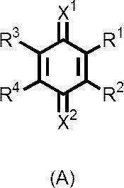
式(A)中、R1、R2、R3、R4はそれぞれ独立に、水素原子または置換基を表す。
R1とR2、または、R3とR4は、同時に置換基となる場合、互いに連結して不飽和縮合環を形成してもよい。この不飽和縮合環は置換基を有していてもよく、その置換基としては、R1~R4において説明する置換基と同様である。
X1およびX2はそれぞれ独立に、酸素原子、硫黄原子、=NR1X基、または、=CR2XR3X基を表す。R1X、R2XおよびR3Xはそれぞれ独立に、水素原子または置換基を表す。R1X~R3Xにおける置換基としては、R1~R4において説明する置換基と同様である。
R1とR2、または、R3とR4は、同時に置換基となる場合、互いに連結して不飽和縮合環を形成してもよい。この不飽和縮合環は置換基を有していてもよく、その置換基としては、R1~R4において説明する置換基と同様である。
X1およびX2はそれぞれ独立に、酸素原子、硫黄原子、=NR1X基、または、=CR2XR3X基を表す。R1X、R2XおよびR3Xはそれぞれ独立に、水素原子または置換基を表す。R1X~R3Xにおける置換基としては、R1~R4において説明する置換基と同様である。
R1~R4によって表される置換基としては、具体的には、アルキル基、アルケニル基、アラルキル基、アリール基、ヘテロ環基、ハロゲン原子、シアノ基、ニトロ基、メルカプト基、ヒドロキシ基、アルコキシ基、アリールオキシ基、アルキルチオ基、アリールチオ基、アシルオキシ基、アミノ基、アルキルアミノ基、カルボンアミド基、スルホンアミド基、スルファモイルアミノ基、オキシカルボニルアミノ基、オキシスルホニルアミノ基、ウレイド基、チオウレイド基、アシル基、オキシカルボニル基、カルバモイル基、スルホニル基、スルフィニル基、スルファモイル基、カルボキシ基(塩を含む)、スルホ基(塩を含む)を挙げることができる。これらは、さらに、これらの置換基で置換されていてもよい。
さらに詳しくR1、R2、R3で表される置換基の例を示す。アルキル基としては、好ましくは炭素数1~18の直鎖、分岐鎖または環状のアルキル基であり、例えば、メチル、エチル、プロピル、イソプロピル、t-ブチル、シクロペンチル、シクロヘキシル、2-ヒドロキシエチル、3-ヒドロキシプロピル、4-ヒドロキシブチル、3-メトキシプロピル、2-アミノエチル、アセトアミドメチル、2-アセトアミドエチル、カルボキシメチル、2-カルボキシエチル、2-スルホエチル、ウレイドメチル、2-ウレイドエチル、カルバモイルメチル、2-カルバモイルエチル、3-カルバモイルプロピル、ペンチル、ヘキシル、オクチル、デシル、ウンデシル、ドデシル、ヘキサデシル、および、オクタデシルなどを挙げることができる。
アルケニル基としては、好ましくは炭素数2~18の直鎖、分岐鎖または環状のアルケニル基であり、例えば、ビニル、アリル、1-プロペニル、2-ペンテニル、1,3-ブタジエニル、2-オクテニル、および、3-ドデセニルなどを挙げることができる。
アルケニル基としては、好ましくは炭素数2~18の直鎖、分岐鎖または環状のアルケニル基であり、例えば、ビニル、アリル、1-プロペニル、2-ペンテニル、1,3-ブタジエニル、2-オクテニル、および、3-ドデセニルなどを挙げることができる。
アラルキル基としては、好ましくは炭素数7~10のアラルキル基であり、例えば、ベンジルなどが挙げられる。
アリール基としては、好ましくは炭素数6~10のアリール基であり、例えば、フェニル、ナフチル、p-ジブチルアミノフェニル、および、p-メトキシフェニルなどが挙げられる。
ヘテロ環基としては、好ましくは、炭素原子、窒素原子、酸素原子、または硫黄原子から構成される5~6員環の飽和または不飽和のヘテロ環基が挙げられる。環を構成するヘテロ原子の数及び元素の種類は1つでも複数であってもよく、例えば、フリル、ベンゾフリル、ピラニル、ピロリル、イミダゾリル、イソオキサゾリル、ピラゾリル、ベンゾトリアゾリル、ピリジル、ピリミジル、ピリダジニル、チエニル、インドリル、キノリル、フタラジニル、キノキサリニル、ピロリジニル、ピロリニル、イミダゾリジニル、イミダゾリニル、ピラゾリジニル、ピペリジル、ピペラジニル、インドリニル、および、モルホリニルなどが挙げられる。
ハロゲン原子としては、例えば、フッ素原子、塩素原子、および、臭素原子などが挙げられる。
アルコキシ基としては、好ましくは炭素数1~18のアルコキシ基であり、例えば、メトキシ、エトキシ、プロポキシ、イソプロポキシ、ブトキシ、2-メトキシエトキシ、2-メタンスルホニルエトキシ、ペンチルオキシ、ヘキシルオキシ、オクチルオキシ、ウンデシルオキシ、ドデシルオキシ、ヘキサデシルオキシ、および、オクタデシルオキシなどを挙げることができる。
アリールオキシ基としては、好ましくは炭素数6~10のアリールオキシ基が挙げられ、例えば、フェノキシ、および、p-メトキシフェノキシなどを挙げることができる。
アルキルチオ基としては、好ましくは炭素数1~18のアルキルチオ基が挙げられ、例えば、メチルチオ、エチルチオ、オクチルチオ、ウンデシルチオ、ドデシルチオ、ヘキサデシルチオ、および、オクタデシルチオなどが挙げられる。
アリールチオ基としては、好ましくは炭素数6~10のアリールチオ基であり、例えば、フェニルチオ、および、4-メトキシフェニルチオなどを挙げることができる。
アシルオキシ基としては、好ましくは炭素数1~18のアシルオキシ基であり、例えば、アセトキシ、プロパノイルオキシ、ペンタノイルオキシ、オクタノイルオキシ、ドデカノイルオキシ、および、オクタデカノイルオキシなどを挙げることができる。
アリール基としては、好ましくは炭素数6~10のアリール基であり、例えば、フェニル、ナフチル、p-ジブチルアミノフェニル、および、p-メトキシフェニルなどが挙げられる。
ヘテロ環基としては、好ましくは、炭素原子、窒素原子、酸素原子、または硫黄原子から構成される5~6員環の飽和または不飽和のヘテロ環基が挙げられる。環を構成するヘテロ原子の数及び元素の種類は1つでも複数であってもよく、例えば、フリル、ベンゾフリル、ピラニル、ピロリル、イミダゾリル、イソオキサゾリル、ピラゾリル、ベンゾトリアゾリル、ピリジル、ピリミジル、ピリダジニル、チエニル、インドリル、キノリル、フタラジニル、キノキサリニル、ピロリジニル、ピロリニル、イミダゾリジニル、イミダゾリニル、ピラゾリジニル、ピペリジル、ピペラジニル、インドリニル、および、モルホリニルなどが挙げられる。
ハロゲン原子としては、例えば、フッ素原子、塩素原子、および、臭素原子などが挙げられる。
アルコキシ基としては、好ましくは炭素数1~18のアルコキシ基であり、例えば、メトキシ、エトキシ、プロポキシ、イソプロポキシ、ブトキシ、2-メトキシエトキシ、2-メタンスルホニルエトキシ、ペンチルオキシ、ヘキシルオキシ、オクチルオキシ、ウンデシルオキシ、ドデシルオキシ、ヘキサデシルオキシ、および、オクタデシルオキシなどを挙げることができる。
アリールオキシ基としては、好ましくは炭素数6~10のアリールオキシ基が挙げられ、例えば、フェノキシ、および、p-メトキシフェノキシなどを挙げることができる。
アルキルチオ基としては、好ましくは炭素数1~18のアルキルチオ基が挙げられ、例えば、メチルチオ、エチルチオ、オクチルチオ、ウンデシルチオ、ドデシルチオ、ヘキサデシルチオ、および、オクタデシルチオなどが挙げられる。
アリールチオ基としては、好ましくは炭素数6~10のアリールチオ基であり、例えば、フェニルチオ、および、4-メトキシフェニルチオなどを挙げることができる。
アシルオキシ基としては、好ましくは炭素数1~18のアシルオキシ基であり、例えば、アセトキシ、プロパノイルオキシ、ペンタノイルオキシ、オクタノイルオキシ、ドデカノイルオキシ、および、オクタデカノイルオキシなどを挙げることができる。
アルキルアミノ基としては、好ましくは炭素数1~18であり、例えば、メチルアミノ、ジメチルアミノ、ジエチルアミノ、ジブチルアミノ、オクチルアミノ、ジオクチルアミノ、および、ウンデシルアミノなどが挙げられる。
カルボンアミド基としては、好ましくは炭素数1~18のカルボンアミド基であり、例えば、ホルムアミド、アセトアミド、アセチルメチルアミノ、アセチルオクチルアミノ、アセチルデシルアミノ、アセチルウンデシルアミノ、アセチルオクタデシルアミノ、プロパノイルアミノ、ペンタノイルアミノ、オクタノイルアミノ、オクタノイルメチルアミノ、ドデカノイルアミノ、ドデカノイルメチルアミノ、および、オクタデカノイルアミノなどが挙げられる。
スルホンアミド基としては、好ましくは炭素数1~18のスルホンアミド基であり、例えば、メタンスルホンアミド、エタンスルホンアミド、プロピルスルホンアミド、2-メトキシエチルスルホンアミド、3-アミノプロピルスルホンアミド、2-アセトアミドエチルスルホンアミド、オクチルスルホンアミド、および、ウンデシルスルホンアミドなどが挙げられる。
オキシカルボニルアミノ基としては、好ましくは炭素数1~18のオキシカルボニルアミノ基であり、例えば、メトキシカルボニルアミノ、エトキシカルボニルアミノ、オクチルオキシカルボニルアミノ、および、ウンデシルオキシカルボニルアミノなどが挙げられる。
オキシスルホニルアミノ基としては、好ましくは炭素数1~18のオキシスルホニルアミノ基であり、例えば、メトキシスルホニルアミノ、エトキシスルホニルアミノ、オクチルオキシスルホニルアミノ、および、ウンデシルオキシスルホニルアミノなどが挙げられる。
スルファモイルアミノ基としては、好ましくは炭素数0~18のスルファモイルアミノ基であり、例えば、メチルスルファモイルアミノ、ジメチルスルファモイルアミノ、エチルスルファモイルアミノ、プロピルスルファモイルアミノ、オクチルスルファモイルアミノ、および、ウンデシルスルファモイルアミノなどが挙げられる。
ウレイド基としては、好ましくは炭素数1~18のウレイド基であり、例えば、ウレイド、メチルウレイド、N,Nージメチルウレイド、オクチルウレイド、および、ウンデシルウレイドなどが挙げられる。
チオウレイド基としては、好ましくは炭素数1~18のチオウレイド基であり、例えば、チオウレイド、メチルチオウレイド、N,N-ジメチルチオウレイド、オクチルチオウレイド、および、ウンデシルチオウレイドなどが挙げられる。
アシル基としては、好ましくは炭素数1~18のアシル基であり、例えば、アセチル、ベンゾイル、オクタノイル、デカノイル、ウンデカノイル、および、オクタデカノイルなどである。
オキシカルボニル基としては、好ましくは炭素数1~18のオキシカルボニル基であり、例えば、メトキシカルボニル、エトキシカルボニル、オクチルオキシカルボニル、および、ウンデシルオキシカルボニルなどが挙げられる。
カルバモイル基としては、好ましくは炭素数1~18のカルバモイル基であり、例えば、カルバモイル、N,Nージメチルカルバモイル、N-エチルカルバモイル、N-オクチルカルバモイル、N,N-ジオクチルカルバモイル、および、N-ウンデシルカルバモイルなどが挙げられる。
スルホニル基としては、好ましくは炭素数1~18のスルホニル基であり、例えば、メタンスルホニル、エタンスルホニル、2-クロロエタンスルホニル、オクタンスルホニル、および、ウンデカンスルホニルなどが挙げられる。
スルフィニル基としては、好ましくは炭素数1~18のスルフィニル基であり、例えば、メタンスルフィニル、エタンスルフィニル、および、オクタンスルフィニルなどが挙げられる。
スルファモイル基としては、好ましくは炭素数0~18のスルファモイル基であり、例えば、スルファモイル、ジメチルスルファモイル、エチルスルファモイル、オクチルスルファモイル、ジオクチルスルファモイル、および、ウンデシルスルファモイルなどが挙げられる。
カルボンアミド基としては、好ましくは炭素数1~18のカルボンアミド基であり、例えば、ホルムアミド、アセトアミド、アセチルメチルアミノ、アセチルオクチルアミノ、アセチルデシルアミノ、アセチルウンデシルアミノ、アセチルオクタデシルアミノ、プロパノイルアミノ、ペンタノイルアミノ、オクタノイルアミノ、オクタノイルメチルアミノ、ドデカノイルアミノ、ドデカノイルメチルアミノ、および、オクタデカノイルアミノなどが挙げられる。
スルホンアミド基としては、好ましくは炭素数1~18のスルホンアミド基であり、例えば、メタンスルホンアミド、エタンスルホンアミド、プロピルスルホンアミド、2-メトキシエチルスルホンアミド、3-アミノプロピルスルホンアミド、2-アセトアミドエチルスルホンアミド、オクチルスルホンアミド、および、ウンデシルスルホンアミドなどが挙げられる。
オキシカルボニルアミノ基としては、好ましくは炭素数1~18のオキシカルボニルアミノ基であり、例えば、メトキシカルボニルアミノ、エトキシカルボニルアミノ、オクチルオキシカルボニルアミノ、および、ウンデシルオキシカルボニルアミノなどが挙げられる。
オキシスルホニルアミノ基としては、好ましくは炭素数1~18のオキシスルホニルアミノ基であり、例えば、メトキシスルホニルアミノ、エトキシスルホニルアミノ、オクチルオキシスルホニルアミノ、および、ウンデシルオキシスルホニルアミノなどが挙げられる。
スルファモイルアミノ基としては、好ましくは炭素数0~18のスルファモイルアミノ基であり、例えば、メチルスルファモイルアミノ、ジメチルスルファモイルアミノ、エチルスルファモイルアミノ、プロピルスルファモイルアミノ、オクチルスルファモイルアミノ、および、ウンデシルスルファモイルアミノなどが挙げられる。
ウレイド基としては、好ましくは炭素数1~18のウレイド基であり、例えば、ウレイド、メチルウレイド、N,Nージメチルウレイド、オクチルウレイド、および、ウンデシルウレイドなどが挙げられる。
チオウレイド基としては、好ましくは炭素数1~18のチオウレイド基であり、例えば、チオウレイド、メチルチオウレイド、N,N-ジメチルチオウレイド、オクチルチオウレイド、および、ウンデシルチオウレイドなどが挙げられる。
アシル基としては、好ましくは炭素数1~18のアシル基であり、例えば、アセチル、ベンゾイル、オクタノイル、デカノイル、ウンデカノイル、および、オクタデカノイルなどである。
オキシカルボニル基としては、好ましくは炭素数1~18のオキシカルボニル基であり、例えば、メトキシカルボニル、エトキシカルボニル、オクチルオキシカルボニル、および、ウンデシルオキシカルボニルなどが挙げられる。
カルバモイル基としては、好ましくは炭素数1~18のカルバモイル基であり、例えば、カルバモイル、N,Nージメチルカルバモイル、N-エチルカルバモイル、N-オクチルカルバモイル、N,N-ジオクチルカルバモイル、および、N-ウンデシルカルバモイルなどが挙げられる。
スルホニル基としては、好ましくは炭素数1~18のスルホニル基であり、例えば、メタンスルホニル、エタンスルホニル、2-クロロエタンスルホニル、オクタンスルホニル、および、ウンデカンスルホニルなどが挙げられる。
スルフィニル基としては、好ましくは炭素数1~18のスルフィニル基であり、例えば、メタンスルフィニル、エタンスルフィニル、および、オクタンスルフィニルなどが挙げられる。
スルファモイル基としては、好ましくは炭素数0~18のスルファモイル基であり、例えば、スルファモイル、ジメチルスルファモイル、エチルスルファモイル、オクチルスルファモイル、ジオクチルスルファモイル、および、ウンデシルスルファモイルなどが挙げられる。
X1およびX2は、それぞれ独立に、酸素原子、硫黄原子、=NR1X基、または、=CR2XR3X基を表すが、酸素原子または=C(R2X)(R3X)基が好ましく、同時に酸素原子または同時に=C(R2X)(R3X)基となることがより好ましい。
R1X~R3Xは、それぞれ独立に、水素原子または置換基を表し、置換基の具体例は、R1~R4において説明した置換基と同様である。
R1X~R3Xは、それぞれ独立に、水素原子または置換基を表し、置換基の具体例は、R1~R4において説明した置換基と同様である。
X1およびX2が同時に酸素原子となる場合において、R1~R4としては、それぞれ独立に、アルキル基、アリール基、ハロゲン原子、シアノ基、ニトロ基、アルコキシ基、アルキルチオ基、アミノ基、アルキルアミノ基、カルボンアミド基、スルホンアミド基、スルファモイルアミノ基、オキシカルボニルアミノ基、オキシスルホニルアミノ基、ウレイド基、チオウレイド基、アシル基、オキシカルボニル基、カルバモイル基、スルホニル基、スルフィニル基、スルファモイル基、およびこれらの基を組み合わせた基、ならびに、水素原子が好ましく、アルキル基、アリール基、ハロゲン原子、シアノ基、アルキルチオ基、カルボンアミド基、およびこれらの基を組み合わせた基、ならびに、水素原子がより好ましい。
R2XおよびR3Xは、それぞれ独立に、水素原子または置換基を表すが、置換基であることが好ましく、ハロゲン原子、シアノ基、アシル基、オキシカルボニル基またはスルホニル基であることがより好ましく、シアノ基であることがさらに好ましく、同時にシアノ基になることが特に好ましい。
一般式(1)で表される化合物としては、X1およびX2が同時に=CR2XR3X基となり、かつ、R2XおよびR3Xが同時にシアノ基である化合物も好ましく用いることができる。このような化合物としては、具体的には、以下の式(AQ)で表される化合物が好ましく用いられる。
一般式(1)で表される化合物としては、X1およびX2が同時に=CR2XR3X基となり、かつ、R2XおよびR3Xが同時にシアノ基である化合物も好ましく用いることができる。このような化合物としては、具体的には、以下の式(AQ)で表される化合物が好ましく用いられる。
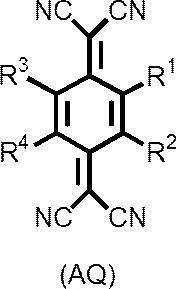
式(AQ)中、R1~R4は、同一でも異なっていてもよく、上記式(A)におけるR1~R4と同義である。
一般式(AQ)で表される化合物の中でも、以下の式(AQ-1)または式(AQ-2)で表される化合物が好ましい。

一般式(AQ-1)中、R31はハロゲン原子、シアノ基、フェニル基、アルコキシ基、アルキルチオ基、カルボンアミド基、スルホンアミド基、ウレイド基、アシル基、オキシカルボニル基を表し、R031はR1~R4にて説明したものと同じものが挙げられる。m4は1~4の整数を表し、m4または4-m4が2以上の整数を表すとき、複数のR31および複数のR031はそれぞれ、互いに同一でも異なっていてもよい。
一般式(AQ-1)中のR31およびR031について以下にその好ましい組み合わせについて述べる。
R31がハロゲン原子、シアノ基、炭素数1~18のアルコキシ基、炭素数1~18のアシル基または炭素数1~18のオキシカルボニル基であり、かつ、R031が水素原子、炭素数1~18のアルキル基またはR031の数を表す「4-m4」が0である場合(すなわち、R031で置換されていない場合)である組み合わせが好ましい。
より好ましくは、R31が炭素数1~18のアルコキシ基もしくはハロゲン原子であり、かつ、R031が水素原子またはR031の数を表す「4-m4」が0である場合の組み合わせである。
R31がハロゲン原子、シアノ基、炭素数1~18のアルコキシ基、炭素数1~18のアシル基または炭素数1~18のオキシカルボニル基であり、かつ、R031が水素原子、炭素数1~18のアルキル基またはR031の数を表す「4-m4」が0である場合(すなわち、R031で置換されていない場合)である組み合わせが好ましい。
より好ましくは、R31が炭素数1~18のアルコキシ基もしくはハロゲン原子であり、かつ、R031が水素原子またはR031の数を表す「4-m4」が0である場合の組み合わせである。
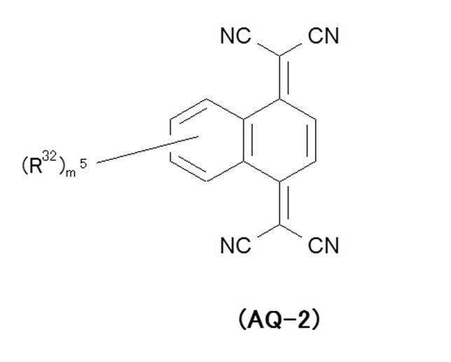
上記式(AQ-2)中、R32は水素原子または置換基を表す。ここで、置換基とは、R1~R4にて説明したものと同じものが挙げられる。m5は0~6の整数を表し、m5が2以上の整数を表すとき、複数のR32は、互いに同一でも異なっていてもよい。
式(AQ-2)中のR32は、好ましくは水素原子、アルキル基、ハロゲン原子、シアノ基、アルコキシ基、アルキルチオ基、カルボンアミド基、スルホンアミド基、ウレイド基、および、アシル基であり、より好ましくは、水素原子、炭素数8~18のアルキル基、ハロゲン原子、シアノ基、炭素数8~18のアルコキシ基、炭素数8~18のアルキルチオ基、炭素数8~18のカルボンアミド基、炭素数8~18のスルホンアミド基、炭素数8~18のウレイド基、および、炭素数8~18のアシル基であり、さらに好ましくは、水素原子、炭素数8~18のアルキル基、フッ素原子、塩素原子、臭素原子、シアノ基、および、炭素数8~18のアルコキシ基であり、特に好ましくは、水素原子である。
以下にキノン構造を有する酸化剤の具体例を挙げるが、これらに限定されるものではない。


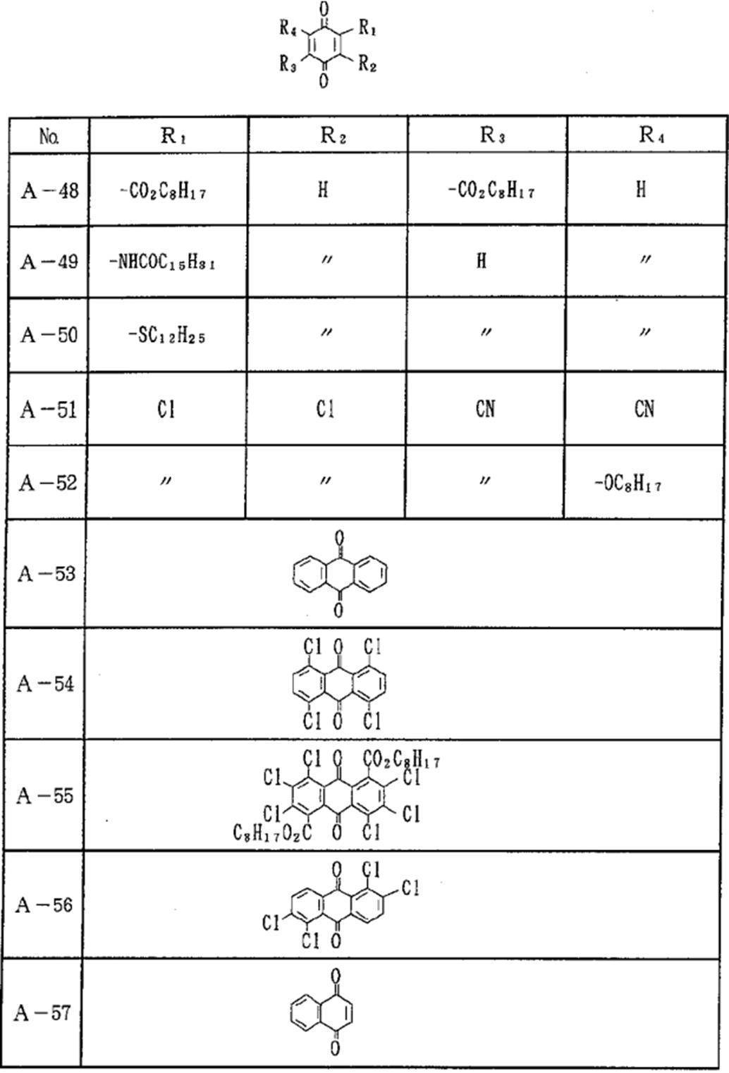
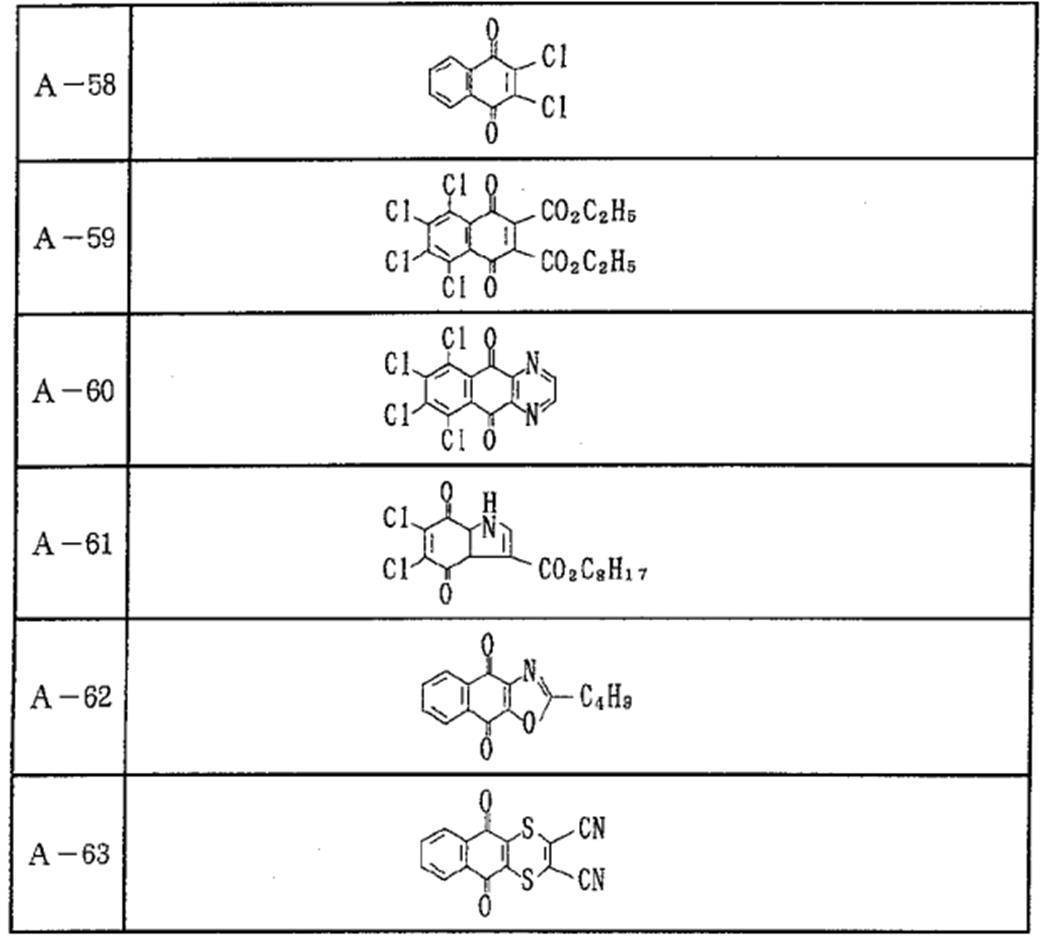


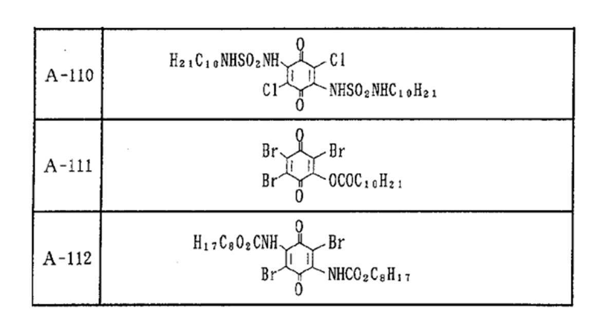


(N-オキシル構造を有する酸化剤)
N-オキシル構造を有する酸化剤は、光吸収異方性膜の耐光性がより向上するという観点から、下記式(N)で表される化合物が好ましい。
N-オキシル構造を有する酸化剤は、光吸収異方性膜の耐光性がより向上するという観点から、下記式(N)で表される化合物が好ましい。
式(N)中、R11、R12、R15およびR16は、それぞれ独立に、水素原子、アルキル基またはアリール基を表す。
式(N)中、R13およびR14は、それぞれ独立に、アルキル基、アリール基またはアルコキシ基を表す。R13およびR14がアルキル基またはアルコキシ基である場合には、R13およびR14が互いに連結して環を構成してもよい。
式(N)中、R13およびR14は、それぞれ独立に、アルキル基、アリール基またはアルコキシ基を表す。R13およびR14がアルキル基またはアルコキシ基である場合には、R13およびR14が互いに連結して環を構成してもよい。
R11~R16におけるアルキル基としては、好ましくは炭素数1~18の直鎖、分岐鎖または環状のアルキル基であり、例えば、メチル、エチル、プロピル、イソプロピル、t-ブチル、シクロペンチル、シクロヘキシル、ペンチル、ヘキシル、オクチル、デシル、ウンデシル、ドデシル、ヘキサデシル、および、オクタデシルなどを挙げることができる。
これらの中でも、R11~R16におけるアルキル基としては、炭素数1~6の直鎖、分岐鎖状または環状のアルキル基が好ましく、炭素数1~6の直鎖または分岐鎖状のアルキル基がより好ましく、炭素数1~6の直鎖のアルキル基がさらに好ましい。
これらの中でも、R11~R16におけるアルキル基としては、炭素数1~6の直鎖、分岐鎖状または環状のアルキル基が好ましく、炭素数1~6の直鎖または分岐鎖状のアルキル基がより好ましく、炭素数1~6の直鎖のアルキル基がさらに好ましい。
R11~R16におけるアリール基としては、好ましくは炭素数6~10のアリール基であり、例えば、フェニルおよびナフチルなどが挙げられる。
R13およびR14におけるアルコキシ基としては、好ましくは炭素数1~18のアルコキシ基であり、例えば、メトキシ、エトキシ、プロポキシ、イソプロポキシ、ブトキシ、ペンチルオキシ、ヘキシルオキシ、オクチルオキシ、ウンデシルオキシ、ドデシルオキシ、ヘキサデシルオキシ、および、オクタデシルオキシなどを挙げることができる。
これらの中でも、R13およびR14におけるアルコキシ基としては、炭素数1~6のアルコキシ基が好ましい。
これらの中でも、R13およびR14におけるアルコキシ基としては、炭素数1~6のアルコキシ基が好ましい。
R13およびR14がアルキル基またはアルコキシ基である場合には、R13およびR14が互いに連結して、環を構成してもよい。この場合、式(N)は、少なくとも窒素原子を含む飽和の複素環骨格(飽和の含窒素複素環骨格)を有する。
このような飽和の含窒素複素環骨格は、5~8員環が好ましく、5~6員環がより好ましい。
飽和の含窒素複素環骨格としては、例えば、ピロリジン骨格、ピペリジン骨格、モルホリン骨格およびオキサゾリジン骨格が挙げられる。
飽和の複素環骨格における複素環は、置換基を有してもよい。置換基の具体例は、上記式(A)のR1~R4において説明した置換基と同様である。また、これらの置換基同士が互いに結合して環を形成してもよく、この場合の式(N)で表される化合物としては、例えば、環を構成する炭素原子の少なくとも1つが窒素原子で置換されたアダマンタン誘導体などの架橋環式骨格を有する化合物が挙げられる。
このような飽和の含窒素複素環骨格は、5~8員環が好ましく、5~6員環がより好ましい。
飽和の含窒素複素環骨格としては、例えば、ピロリジン骨格、ピペリジン骨格、モルホリン骨格およびオキサゾリジン骨格が挙げられる。
飽和の複素環骨格における複素環は、置換基を有してもよい。置換基の具体例は、上記式(A)のR1~R4において説明した置換基と同様である。また、これらの置換基同士が互いに結合して環を形成してもよく、この場合の式(N)で表される化合物としては、例えば、環を構成する炭素原子の少なくとも1つが窒素原子で置換されたアダマンタン誘導体などの架橋環式骨格を有する化合物が挙げられる。
R11~R16におけるアリール基およびアルキル基、ならびに、R13およびR14におけるアルコキシ基は、置換基を有していてもよい。置換基としては、上記式(A)のR1~R4において説明した置換基、および、酸素原子(=O)等が挙げられる。
上記式(N)で表される化合物の中でも、光吸収異方性膜の耐光性がより向上する観点から、下記式(N1)で表される構造、または、下記式(N2)で表される構造を有する化合物が好ましい。

上記式(N1)中、R21~R28はそれぞれ独立に、水素原子または置換基を表す。R21~R28からなる群より選択される2個以上の基が置換基である場合、2個以上の置換基同士が互いに連結して環を形成してもよい。
R21~R28が表す置換基としては、上記式(A)のR1~R4において説明した置換基、および、酸素原子(=O)が挙げられる。ただし、R21~R28が酸素原子である場合、R21およびR22の両方で1つの酸素原子(=O)を表し、R23およびR24の両方で1つの酸素原子(=O)を表し、R25およびR26の両方で1つの酸素原子(=O)を表し、R27およびR28の両方で1つの酸素原子(=O)を表す。
R21~R28が表す置換基としては、上記式(A)のR1~R4において説明した置換基、および、酸素原子(=O)が挙げられる。ただし、R21~R28が酸素原子である場合、R21およびR22の両方で1つの酸素原子(=O)を表し、R23およびR24の両方で1つの酸素原子(=O)を表し、R25およびR26の両方で1つの酸素原子(=O)を表し、R27およびR28の両方で1つの酸素原子(=O)を表す。
上記の中でも、R21~R28は、それぞれ独立に、水素原子、酸素原子、ヒドロキシ基、アルキル基、アルコキシ基、アリール基、アリールオキシ基、カルバモイル基、カルボキシ基、アシルオキシ基、カルボンアミド基またはスルホンアミド基であるのが好ましい。これらの中でも、2色性色素化合物と親水性または疎水性の性質が近くなり、耐光性向上をさせる効果がより発揮できる観点から、炭素数1~20のアルキル基、カルボンアミド基、または、スルホンアミド基がより好ましい。
R21~R28のうち、2個以上の置換基が互いに連結して環を形成する場合、式(N1)で表される化合物は、上述したような架橋環式骨格を有する化合物であることが好ましい。このような架橋環式骨格を有する化合物は、これ自体の活性が高く、酸化抑制機能が良好に発揮できる。これにより、光吸収異方性膜の耐光性がより向上する。
R21~R28のうち、2個以上の置換基が互いに連結して環を形成する場合、式(N1)で表される化合物は、上述したような架橋環式骨格を有する化合物であることが好ましい。このような架橋環式骨格を有する化合物は、これ自体の活性が高く、酸化抑制機能が良好に発揮できる。これにより、光吸収異方性膜の耐光性がより向上する。
上記式(N2)中、R31~R40はそれぞれ独立に、水素原子または置換基を表す。R31~R40からなる群より選択される2個以上の基が置換基である場合、2個以上の置換基同士が互いに連結して環を形成してもよい。
R31~R40が表す置換基としては、上記式(A)のR1~R4において説明した置換基、および、酸素原子(=O)が挙げられる。ただし、R31~R40が酸素原子である場合、R31およびR32の両方で1つの酸素原子(=O)を表し、R33およびR34の両方で1つの酸素原子(=O)を表し、R35およびR36の両方で1つの酸素原子(=O)を表し、R37およびR38の両方で1つの酸素原子(=O)を表し、R39およびR40の両方で1つの酸素原子(=O)を表す。
上記の中でも、R31~R40は、それぞれ独立に、水素原子、酸素原子、アルキル基、ヒドロキシ基、アルコキシ基、アリール基、アリールオキシ基、カルバモイル基、カルボキシ基、アシルオキシ基、カルボンアミド基またはスルホンアミド基であるのが好ましい。これらの中でも、これらの中でも、2色性色素化合物と親水性または疎水性の性質が近くなり、耐光性向上をさせる効果がより発揮できる観点から、炭素数1~20のアルキル基、カルボンアミド基、または、スルホンアミド基がより好ましい。
R31~R40のうち、2個以上の置換基が互いに連結して環を形成する場合、式(N2)で表される化合物は、上述したような架橋環式骨格を有する化合物であることが好ましい。このような架橋環式骨格を有する化合物は、これ自体の活性が高く、酸化抑制機能が良好に発揮できる。これにより、光吸収異方性膜の耐光性がより向上する。
R31~R40が表す置換基としては、上記式(A)のR1~R4において説明した置換基、および、酸素原子(=O)が挙げられる。ただし、R31~R40が酸素原子である場合、R31およびR32の両方で1つの酸素原子(=O)を表し、R33およびR34の両方で1つの酸素原子(=O)を表し、R35およびR36の両方で1つの酸素原子(=O)を表し、R37およびR38の両方で1つの酸素原子(=O)を表し、R39およびR40の両方で1つの酸素原子(=O)を表す。
上記の中でも、R31~R40は、それぞれ独立に、水素原子、酸素原子、アルキル基、ヒドロキシ基、アルコキシ基、アリール基、アリールオキシ基、カルバモイル基、カルボキシ基、アシルオキシ基、カルボンアミド基またはスルホンアミド基であるのが好ましい。これらの中でも、これらの中でも、2色性色素化合物と親水性または疎水性の性質が近くなり、耐光性向上をさせる効果がより発揮できる観点から、炭素数1~20のアルキル基、カルボンアミド基、または、スルホンアミド基がより好ましい。
R31~R40のうち、2個以上の置換基が互いに連結して環を形成する場合、式(N2)で表される化合物は、上述したような架橋環式骨格を有する化合物であることが好ましい。このような架橋環式骨格を有する化合物は、これ自体の活性が高く、酸化抑制機能が良好に発揮できる。これにより、光吸収異方性膜の耐光性がより向上する。
また、N-オキシル構造を有する酸化剤には、下記式(N3)で表される化合物も用いられる。

上記式(N3)中、R41~R48はそれぞれ独立に、水素原子または置換基を表す。R41~R48からなる群より選択される2個以上の基が置換基である場合、2個以上の置換基同士が互いに連結して環を形成してもよい。
R41~R48が表す置換基は、上記式(A)のR1~R4において説明した置換基、および、酸素原子(=O)が挙げられる。ただし、R41~R48が酸素原子である場合、R41およびR42の両方で1つの酸素原子(=O)を表し、R43およびR44の両方で1つの酸素原子(=O)を表し、R45およびR46の両方で1つの酸素原子(=O)を表し、R47およびR48の両方で1つの酸素原子(=O)を表す。
上記の中でも、R41~R48は、それぞれ独立に、水素原子、酸素原子、アルキル基、ヒドロキシ基、アルコキシ基、アリール基、アリールオキシ基、カルバモイル基、カルボキシ基、アシルオキシ基、カルボンアミド基またはスルホンアミド基であるのが好ましい。これらの中でも、2色性色素化合物と親水性または疎水性の性質が近くなり、耐光性向上をさせる効果がより発揮できる観点から、炭素数1~20のアルキル基、カルボンアミド基、または、スルホンアミド基がより好ましい。
R41~R48のうち、2個以上の置換基が互いに連結して環を形成する場合、式(N3)で表される化合物は、上述したような架橋環式骨格を有する化合物であることが好ましい。このような架橋環式骨格を有する化合物は、これ自体の活性が高く、酸化抑制機能が良好に発揮できる。これにより、光吸収異方性膜の耐光性がより向上する。
R41~R48が表す置換基は、上記式(A)のR1~R4において説明した置換基、および、酸素原子(=O)が挙げられる。ただし、R41~R48が酸素原子である場合、R41およびR42の両方で1つの酸素原子(=O)を表し、R43およびR44の両方で1つの酸素原子(=O)を表し、R45およびR46の両方で1つの酸素原子(=O)を表し、R47およびR48の両方で1つの酸素原子(=O)を表す。
上記の中でも、R41~R48は、それぞれ独立に、水素原子、酸素原子、アルキル基、ヒドロキシ基、アルコキシ基、アリール基、アリールオキシ基、カルバモイル基、カルボキシ基、アシルオキシ基、カルボンアミド基またはスルホンアミド基であるのが好ましい。これらの中でも、2色性色素化合物と親水性または疎水性の性質が近くなり、耐光性向上をさせる効果がより発揮できる観点から、炭素数1~20のアルキル基、カルボンアミド基、または、スルホンアミド基がより好ましい。
R41~R48のうち、2個以上の置換基が互いに連結して環を形成する場合、式(N3)で表される化合物は、上述したような架橋環式骨格を有する化合物であることが好ましい。このような架橋環式骨格を有する化合物は、これ自体の活性が高く、酸化抑制機能が良好に発揮できる。これにより、光吸収異方性膜の耐光性がより向上する。
また、N-オキシル構造を有する酸化剤には、下記式(N4)で表される化合物も用いられる。
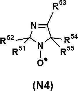
上記式(N4)中、R51~R55はそれぞれ独立に、水素原子または置換基を表す。R51~R55からなる群より選択される2個以上の基が置換基である場合、2個以上の置換基同士が互いに連結して環を形成してもよい。R51~R55が表す置換基は、上記式(A)のR1~R4において説明した置換基と同様であるので、その説明を省略する。
上記の中でも、R51~R55は、それぞれ独立に、水素原子、アルキル基、ヒドロキシ基、アルコキシ基、アリール基、アリールオキシ基、カルバモイル基、カルボキシ基、アシルオキシ基、カルボンアミド基またはスルホンアミド基であるのが好ましい。
上記の中でも、R51~R55は、それぞれ独立に、水素原子、アルキル基、ヒドロキシ基、アルコキシ基、アリール基、アリールオキシ基、カルバモイル基、カルボキシ基、アシルオキシ基、カルボンアミド基またはスルホンアミド基であるのが好ましい。
以下にN-オキシル構造を有する酸化剤の具体例を挙げるが、これらに限定されるものではない。
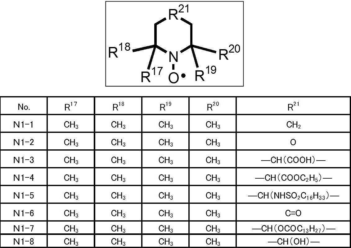
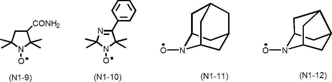
(アミンオキシド構造を有する酸化剤)
酸化剤としては、キノン構造を有する酸化剤およびN-オキシル構造を有する酸化剤の他に、アミンオキシド構造を有する酸化剤を用いてもよい。
アミンオキシド構造を有する酸化剤としては、光吸収異方性膜の耐光性がより向上する観点から、下記式(AO)で表される化合物が好ましい。
酸化剤としては、キノン構造を有する酸化剤およびN-オキシル構造を有する酸化剤の他に、アミンオキシド構造を有する酸化剤を用いてもよい。
アミンオキシド構造を有する酸化剤としては、光吸収異方性膜の耐光性がより向上する観点から、下記式(AO)で表される化合物が好ましい。

上記式(AO)中、R61~R65はそれぞれ独立に、水素原子または置換基を表す。R61~R65からなる群より選択される2個以上の基が置換基である場合、隣接する2個の置換基同士(具体的には、R61とR62、R62とR63、R63とR64、または、R64とR65)が互いに連結して不飽和縮合環を形成してもよい。この不飽和縮合環は置換基を有していてもよく、その置換基としては、R61~R65において説明した置換基と同様である。
R61~R65が表す置換基は、上記式(A)のR1~R4において説明した置換基と同様である。上記の中でも、R61~R65は、それぞれ独立に、水素原子、アルキル基、または、ニトロ基が好ましい。
R61~R65が表す置換基は、上記式(A)のR1~R4において説明した置換基と同様である。上記の中でも、R61~R65は、それぞれ独立に、水素原子、アルキル基、または、ニトロ基が好ましい。
以下にアミンオキシド構造を有する酸化剤の具体例を挙げるが、これらに限定されるものではない。
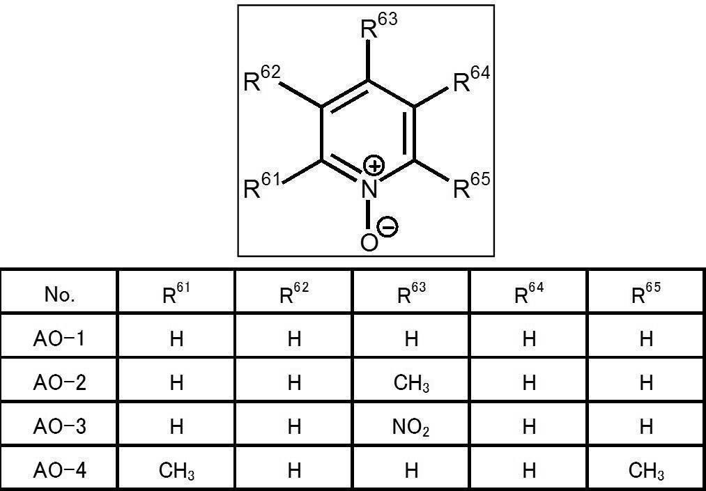

<アゾ基を有する2色性色素化合物>
第1実施形態に係る着色組成物は、アゾ基を有する2色性色素化合物を含有する。
本発明において、2色性色素化合物とは、方向によって吸光度が異なる色素を意味する。また、2色性および2色比は、2色性色素組成物を光吸収異方性膜としたときの、偏光軸方向の偏光の吸光度に対する、吸収軸方向の偏光の吸光度の比で計算される。
アゾ基を有する2色性色素化合物としては、アゾ基を有していれば特に限定されず、従来公知の2色性色素化合物を使用することができる。
具体的には、例えば、特開2013-228706号公報の[0067]~[0071]段落、特開2013-227532号公報の[0008]~[0026]段落、特開2013-209367号公報の[0008]~[0015]段落、特開2013-14883号公報の[0045]~[0058]段落、特開2013-109090号公報の[0013]~[0022]段落、特開2013-101328号公報の[0009]~[0017]段落、特開2013-37353号公報の[0052]~[0059]段落、特開2012-63387号公報の[0050]~[0057]段落、特開平11-305036号公報の[0018]段落、特開2001-133630号公報の[0009]~[0011]段落、および、特開2011-215337号公報の[0030]~[0169]段落などに記載のアゾ基を有する2色性色素化合物が挙げられる。
第1実施形態に係る着色組成物は、アゾ基を有する2色性色素化合物を含有する。
本発明において、2色性色素化合物とは、方向によって吸光度が異なる色素を意味する。また、2色性および2色比は、2色性色素組成物を光吸収異方性膜としたときの、偏光軸方向の偏光の吸光度に対する、吸収軸方向の偏光の吸光度の比で計算される。
アゾ基を有する2色性色素化合物としては、アゾ基を有していれば特に限定されず、従来公知の2色性色素化合物を使用することができる。
具体的には、例えば、特開2013-228706号公報の[0067]~[0071]段落、特開2013-227532号公報の[0008]~[0026]段落、特開2013-209367号公報の[0008]~[0015]段落、特開2013-14883号公報の[0045]~[0058]段落、特開2013-109090号公報の[0013]~[0022]段落、特開2013-101328号公報の[0009]~[0017]段落、特開2013-37353号公報の[0052]~[0059]段落、特開2012-63387号公報の[0050]~[0057]段落、特開平11-305036号公報の[0018]段落、特開2001-133630号公報の[0009]~[0011]段落、および、特開2011-215337号公報の[0030]~[0169]段落などに記載のアゾ基を有する2色性色素化合物が挙げられる。
アゾ基を有する2色性色素化合物は、液晶性を有していることが好ましく、サーモトロピック液晶性またはリオトロピック液晶性であることがより好ましく、サーモトロピック液晶性であることがさらに好ましい。ここで、サーモトロピック液晶性とは、熱によって液晶相に転移して、液晶性を示すことをいう。また、リオトロピック液晶性とは、濃度変化によって液晶相に転移して、液晶性を示すことをいう。
このようなサーモトロピック液晶性を有し、アゾ基を有する2色性色素化合物としては、例えば、特開2011-237513号公報の[0056]~[0219]段落に記載のアゾ色素が好ましく用いられる。
このようなサーモトロピック液晶性を有し、アゾ基を有する2色性色素化合物としては、例えば、特開2011-237513号公報の[0056]~[0219]段落に記載のアゾ色素が好ましく用いられる。
アゾ基を有する2色性色素化合物は、1種単独で使用してもよいし、2種以上を併用してもよい。
上記アゾ基を有する2色性色素化合物として、下記式(D1)で表される部分構造を有する2色性色素化合物を使用する場合、上述したN-オキシル構造を有する酸化剤を使用することが好ましい。これにより、光吸収異方性膜の耐光性がより向上する。

上記式(D1)中、Ar1およびAr2はそれぞれ独立に、芳香族炭化水素環または複素環を表し、nは1、3または4の整数を表し、*は他の基との結合位置を表す。nが3または4である場合、複数のAr2は互いに同一でも異なっていてもよい。
ただし、上記式(D1)の両末端に位置するAr1およびAr2において、他の基との結合位置*における結合手はいずれも、アゾ基(-N=N-)と直接結合することはない。すなわち、上記式(D1)のAr1の左側の結合手がアゾ基と直接結合せず、かつ、上記式(D1)の最も右側に存在するAr2の右側の結合手がアゾ基と直接結合しないという意味である。
ただし、上記式(D1)の両末端に位置するAr1およびAr2において、他の基との結合位置*における結合手はいずれも、アゾ基(-N=N-)と直接結合することはない。すなわち、上記式(D1)のAr1の左側の結合手がアゾ基と直接結合せず、かつ、上記式(D1)の最も右側に存在するAr2の右側の結合手がアゾ基と直接結合しないという意味である。
Ar1およびAr2が表す芳香族炭化水素基は、単環であっても、2環以上の縮環構造を有していてもよい。芳香族炭化水素環の環数は、1~4が好ましく、1~2がより好ましく、1(すなわちベンゼン環であること)がさらに好ましい。
芳香族炭化水素環の具体例としては、ベンゼン環、アズレン環、ナフタレン環、フルオレン環、アントラセン環、テトラセン環などが挙げられ、ベンゼン環およびナフタレン環が好ましく、ベンゼン環がより好ましい。
Ar1およびAr2が表す複素環は、芳香族または非芳香族のいずれであってもよいが、2色比が向上するという観点から、芳香族複素環が好ましい。
芳香族複素環は、単環であってもよいし、2環以上の縮環構造を有していてもよい。芳香族複素環を構成する炭素以外の原子としては、窒素原子、硫黄原子および酸素原子が挙げられる。芳香族複素環が炭素以外の環を構成する原子を複数有する場合、これらは同一であっても異なっていてもよい。
芳香族複素環の具体例としては、例えば、ピリジン環、チオフェン環、キノリン環、イソキノリン環、チアゾール環、ベンゾチアジアゾール環、フタルイミド環、チエノチアゾール環、チエノチオフェン環、および、チエノオキサゾール環等が挙げられ、チエノチアゾール環が好ましい。
芳香族炭化水素環の具体例としては、ベンゼン環、アズレン環、ナフタレン環、フルオレン環、アントラセン環、テトラセン環などが挙げられ、ベンゼン環およびナフタレン環が好ましく、ベンゼン環がより好ましい。
Ar1およびAr2が表す複素環は、芳香族または非芳香族のいずれであってもよいが、2色比が向上するという観点から、芳香族複素環が好ましい。
芳香族複素環は、単環であってもよいし、2環以上の縮環構造を有していてもよい。芳香族複素環を構成する炭素以外の原子としては、窒素原子、硫黄原子および酸素原子が挙げられる。芳香族複素環が炭素以外の環を構成する原子を複数有する場合、これらは同一であっても異なっていてもよい。
芳香族複素環の具体例としては、例えば、ピリジン環、チオフェン環、キノリン環、イソキノリン環、チアゾール環、ベンゾチアジアゾール環、フタルイミド環、チエノチアゾール環、チエノチオフェン環、および、チエノオキサゾール環等が挙げられ、チエノチアゾール環が好ましい。
上記アゾ基を有する2色性色素化合物として、下記式(D2)で表される部分構造を有する2色性色素化合物を使用する場合、上述したキノン構造を有する酸化剤を使用することが好ましい。これにより、光吸収異方性膜の耐光性がより向上する。

上記式(D2)中、Ar3およびAr4はそれぞれ独立に、芳香族炭化水素環または複素環を表し、*は他の基との結合位置を表す。Ar3およびAr4の定義は、上記式(D1)におけるAr1およびAr2と同様であるのでその説明を省略する。
ただし、Ar3およびAr4において、他の基との結合位置*における結合手はいずれも、アゾ基と直接結合することはない。すなわち、上記式(D2)のAr3の左側の結合手がアゾ基と直接結合せず、かつ、上記式(D2)のAr4の右側の結合手がアゾ基と直接結合しないという意味である。
ただし、Ar3およびAr4において、他の基との結合位置*における結合手はいずれも、アゾ基と直接結合することはない。すなわち、上記式(D2)のAr3の左側の結合手がアゾ基と直接結合せず、かつ、上記式(D2)のAr4の右側の結合手がアゾ基と直接結合しないという意味である。
<液晶性化合物>
第1実施形態に係る着色組成物は、液晶性化合物を含有することが好ましい。液晶性化合物を含むことで、2色性色素化合物の析出を抑止しながら、2色性色素化合物を高い配向度で配向させることができる。
液晶性化合物は、上記アゾ基を有する2色性色素以外の液晶性化合物である。
液晶性化合物としては、低分子液晶性化合物および高分子液晶性化合物のいずれも用いることができる。ここで、「低分子液晶性化合物」とは、化学構造中に繰り返し単位を有さない液晶性化合物のことをいう。また、「高分子液晶性化合物」とは、化学構造中に繰り返し単位を有する液晶性化合物のことをいう。
低分子液晶性化合物としては、例えば、特開2013-228706号公報に記載されている液晶性化合物が挙げられる。
高分子液晶性化合物としては、例えば、特開2011-237513号公報に記載されているサーモトロピック液晶性高分子、特開2016-4055号公報に記載のサーモトロピック液晶性を有する2色性色素ポリマーが挙げられる。また、高分子液晶性化合物は、末端に架橋性基(例えば、アクリロイル基およびメタクリロイル基)を有していてもよい。
液晶性化合物は、1種単独で使用してもよいし、2種以上を併用してもよい。
液晶性化合物の含有量は、着色組成物中のアゾ基を有する2色性色素化合物の含有量100質量部に対して、0.1~10,000質量部が好ましく、1~5,000質量部がより好ましく、10~1,000質量部がさらに好ましい。液晶性化合物の含有量が上記範囲内にあることで、光吸収異方性膜の2色比が向上する。
第1実施形態に係る着色組成物は、液晶性化合物を含有することが好ましい。液晶性化合物を含むことで、2色性色素化合物の析出を抑止しながら、2色性色素化合物を高い配向度で配向させることができる。
液晶性化合物は、上記アゾ基を有する2色性色素以外の液晶性化合物である。
液晶性化合物としては、低分子液晶性化合物および高分子液晶性化合物のいずれも用いることができる。ここで、「低分子液晶性化合物」とは、化学構造中に繰り返し単位を有さない液晶性化合物のことをいう。また、「高分子液晶性化合物」とは、化学構造中に繰り返し単位を有する液晶性化合物のことをいう。
低分子液晶性化合物としては、例えば、特開2013-228706号公報に記載されている液晶性化合物が挙げられる。
高分子液晶性化合物としては、例えば、特開2011-237513号公報に記載されているサーモトロピック液晶性高分子、特開2016-4055号公報に記載のサーモトロピック液晶性を有する2色性色素ポリマーが挙げられる。また、高分子液晶性化合物は、末端に架橋性基(例えば、アクリロイル基およびメタクリロイル基)を有していてもよい。
液晶性化合物は、1種単独で使用してもよいし、2種以上を併用してもよい。
液晶性化合物の含有量は、着色組成物中のアゾ基を有する2色性色素化合物の含有量100質量部に対して、0.1~10,000質量部が好ましく、1~5,000質量部がより好ましく、10~1,000質量部がさらに好ましい。液晶性化合物の含有量が上記範囲内にあることで、光吸収異方性膜の2色比が向上する。
<溶媒>
第1実施形態に係る着色組成物は、作業性等の観点から、溶媒を含有するのが好ましい。
溶媒としては、例えば、ケトン類(例えば、アセトン、2-ブタノン、メチルイソブチルケトン、シクロペンタノン、シクロヘキサノンなど)、エーテル類(例えば、ジオキサン、テトラヒドロフラン、シクロペンチルメチルエーテルなど)、脂肪族炭化水素類(例えば、ヘキサンなど)、脂環式炭化水素類(例えば、シクロヘキサンなど)、芳香族炭化水素類(例えば、ベンゼン、トルエン、キシレン、トリメチルベンゼンなど)、ハロゲン化炭素類(例えば、ジクロロメタン、トリクロロメタン(クロロホルム)、ジクロロエタン、ジクロロベンゼン、クロロトルエンなど)、エステル類(例えば、酢酸メチル、酢酸エチル、酢酸ブチルなど)、アルコール類(例えば、エタノール、イソプロパノール、ブタノール、シクロヘキサノールなど)、セロソルブ類(例えば、メチルセロソルブ、エチルセロソルブ、1,2-ジメトキシエタンなど)、セロソルブアセテート類、スルホキシド類(例えば、ジメチルスルホキシドなど)、アミド類(例えば、ジメチルホルムアミド、ジメチルアセトアミドなど)、および、ヘテロ環化合物(例えば、ピリジンなど)などの有機溶媒、ならびに、水が挙げられる。これの溶媒は、1種単独で用いてもよく、2種以上を併用してもよい。
これらの溶媒のうち、有機溶媒を用いることが好ましく、ハロゲン化炭素類またはケトン類を用いることがより好ましい。
着色組成物が溶媒を含有する場合において、溶媒の含有量は、着色組成物の全質量に対して、70~99.5質量%であることが好ましく、85~99.0質量%であることがより好ましく、80~97質量%であることがさらに好ましい。
第1実施形態に係る着色組成物は、作業性等の観点から、溶媒を含有するのが好ましい。
溶媒としては、例えば、ケトン類(例えば、アセトン、2-ブタノン、メチルイソブチルケトン、シクロペンタノン、シクロヘキサノンなど)、エーテル類(例えば、ジオキサン、テトラヒドロフラン、シクロペンチルメチルエーテルなど)、脂肪族炭化水素類(例えば、ヘキサンなど)、脂環式炭化水素類(例えば、シクロヘキサンなど)、芳香族炭化水素類(例えば、ベンゼン、トルエン、キシレン、トリメチルベンゼンなど)、ハロゲン化炭素類(例えば、ジクロロメタン、トリクロロメタン(クロロホルム)、ジクロロエタン、ジクロロベンゼン、クロロトルエンなど)、エステル類(例えば、酢酸メチル、酢酸エチル、酢酸ブチルなど)、アルコール類(例えば、エタノール、イソプロパノール、ブタノール、シクロヘキサノールなど)、セロソルブ類(例えば、メチルセロソルブ、エチルセロソルブ、1,2-ジメトキシエタンなど)、セロソルブアセテート類、スルホキシド類(例えば、ジメチルスルホキシドなど)、アミド類(例えば、ジメチルホルムアミド、ジメチルアセトアミドなど)、および、ヘテロ環化合物(例えば、ピリジンなど)などの有機溶媒、ならびに、水が挙げられる。これの溶媒は、1種単独で用いてもよく、2種以上を併用してもよい。
これらの溶媒のうち、有機溶媒を用いることが好ましく、ハロゲン化炭素類またはケトン類を用いることがより好ましい。
着色組成物が溶媒を含有する場合において、溶媒の含有量は、着色組成物の全質量に対して、70~99.5質量%であることが好ましく、85~99.0質量%であることがより好ましく、80~97質量%であることがさらに好ましい。
<界面改良剤>
第1実施形態に係る着色組成物は、界面改良剤を含有してもよい。界面改良剤を含むことにより、塗布表面の平滑性が向上し、配向度が向上したり、ハジキおよびムラを抑制して、面内の均一性の向上が見込まれる。
界面改良剤としては、アゾ基を有する2色性色素化合物、または、液晶性化合物を塗布表面側で水平にさせるものが好ましく、特開2011-237513号公報の[0253]~[0293]段落に記載の化合物(水平配向剤)を用いることができる。
界面改良剤は、1種単独で使用してもよいし、2種以上を併用してもよい。
着色組成物が界面改良剤を含有する場合、界面改良剤の含有量は、着色組成物中の上記アゾ基を有する2色性色素化合物100質量部に対し、0.001~10質量部が好ましく、0.01~5質量部が好ましい。
第1実施形態に係る着色組成物は、界面改良剤を含有してもよい。界面改良剤を含むことにより、塗布表面の平滑性が向上し、配向度が向上したり、ハジキおよびムラを抑制して、面内の均一性の向上が見込まれる。
界面改良剤としては、アゾ基を有する2色性色素化合物、または、液晶性化合物を塗布表面側で水平にさせるものが好ましく、特開2011-237513号公報の[0253]~[0293]段落に記載の化合物(水平配向剤)を用いることができる。
界面改良剤は、1種単独で使用してもよいし、2種以上を併用してもよい。
着色組成物が界面改良剤を含有する場合、界面改良剤の含有量は、着色組成物中の上記アゾ基を有する2色性色素化合物100質量部に対し、0.001~10質量部が好ましく、0.01~5質量部が好ましい。
<重合開始剤>
第1実施形態に係る着色組成物は、重合開始剤を含有してもよい。
重合開始剤としては特に制限はないが、感光性を有する化合物、すなわち光重合開始剤であることが好ましい。
光重合開始剤としては、各種の化合物を特に制限なく使用できる。光重合開始剤の例には、α-カルボニル化合物(米国特許第2367661号、同2367670号の各明細書)、アシロインエーテル(米国特許第2448828号明細書)、α-炭化水素置換芳香族アシロイン化合物(米国特許第2722512号明細書)、多核キノン化合物(米国特許第3046127号および同2951758号の各明細書)、トリアリールイミダゾールダイマーとp-アミノフェニルケトンとの組み合わせ(米国特許第3549367号明細書)、アクリジンおよびフェナジン化合物(特開昭60-105667号公報および米国特許第4239850号明細書)、オキサジアゾール化合物(米国特許第4212970号明細書)、および、アシルフォスフィンオキシド化合物(特公昭63-40799号公報、特公平5-29234号公報、特開平10-95788号公報および特開平10-29997号公報)等が挙げられる。
このような光重合開始剤としては、市販品も用いることができ、BASF社製のイルガキュア184、イルガキュア907、イルガキュア369、イルガキュア651、イルガキュア819、イルガキュアOXE-01およびイルガキュアOXE-02等が挙げられる。
重合開始剤は、1種単独で使用してもよいし、2種以上を併用してもよい。
着色組成物が重合開始剤を含有する場合、重合開始剤の含有量は、着色組成物中の上記アゾ基を有する2色性色素化合物100質量部に対し、0.01~50質量部が好ましく、0.1~25質量部がより好ましい。
第1実施形態に係る着色組成物は、重合開始剤を含有してもよい。
重合開始剤としては特に制限はないが、感光性を有する化合物、すなわち光重合開始剤であることが好ましい。
光重合開始剤としては、各種の化合物を特に制限なく使用できる。光重合開始剤の例には、α-カルボニル化合物(米国特許第2367661号、同2367670号の各明細書)、アシロインエーテル(米国特許第2448828号明細書)、α-炭化水素置換芳香族アシロイン化合物(米国特許第2722512号明細書)、多核キノン化合物(米国特許第3046127号および同2951758号の各明細書)、トリアリールイミダゾールダイマーとp-アミノフェニルケトンとの組み合わせ(米国特許第3549367号明細書)、アクリジンおよびフェナジン化合物(特開昭60-105667号公報および米国特許第4239850号明細書)、オキサジアゾール化合物(米国特許第4212970号明細書)、および、アシルフォスフィンオキシド化合物(特公昭63-40799号公報、特公平5-29234号公報、特開平10-95788号公報および特開平10-29997号公報)等が挙げられる。
このような光重合開始剤としては、市販品も用いることができ、BASF社製のイルガキュア184、イルガキュア907、イルガキュア369、イルガキュア651、イルガキュア819、イルガキュアOXE-01およびイルガキュアOXE-02等が挙げられる。
重合開始剤は、1種単独で使用してもよいし、2種以上を併用してもよい。
着色組成物が重合開始剤を含有する場合、重合開始剤の含有量は、着色組成物中の上記アゾ基を有する2色性色素化合物100質量部に対し、0.01~50質量部が好ましく、0.1~25質量部がより好ましい。
〔第2実施形態〕
第2実施形態に係る着色組成物は、上記のアゾ基を有する2色性色素化合物と、一重項酸素クエンチャーと、を含有する。
第2実施形態に係る着色組成物は、酸化剤に代えて一重項酸素クエンチャーを含有すること以外は、第1実施形態に係る着色組成物と同様である。以下の第2実施形態に係る着色組成物の説明では、第1実施形態に係る着色組成物との相違点のみを説明する。
第2実施形態に係る着色組成物は、上記のアゾ基を有する2色性色素化合物と、一重項酸素クエンチャーと、を含有する。
第2実施形態に係る着色組成物は、酸化剤に代えて一重項酸素クエンチャーを含有すること以外は、第1実施形態に係る着色組成物と同様である。以下の第2実施形態に係る着色組成物の説明では、第1実施形態に係る着色組成物との相違点のみを説明する。
<一重項酸素クエンチャー>
第2実施形態に係る着色組成物は、一重項酸素クエンチャーを含有する。一重項酸素クエンチャーは、一重項状態酸素と反応して、一重項酸素を失活させ得る化合物である。
一重項酸素クエンチャーは、上述した光吸収異方性膜の耐光性を向上させる機能の他に、光吸収異方性膜の湿熱耐久性を向上させるという機能も有する。
一重項酸素クエンチャーの含有量は、着色組成物中のアゾ基を有する2色性色素化合物100質量部に対して、0.1~100質量部が好ましく、1~50質量部がより好ましく、1~40質量部がさらに好ましい。一重項酸素クエンチャーの含有量が上記範囲内にあることで、光吸収異方性膜の耐光性がより向上する。
第2実施形態に係る着色組成物は、一重項酸素クエンチャーを含有する。一重項酸素クエンチャーは、一重項状態酸素と反応して、一重項酸素を失活させ得る化合物である。
一重項酸素クエンチャーは、上述した光吸収異方性膜の耐光性を向上させる機能の他に、光吸収異方性膜の湿熱耐久性を向上させるという機能も有する。
一重項酸素クエンチャーの含有量は、着色組成物中のアゾ基を有する2色性色素化合物100質量部に対して、0.1~100質量部が好ましく、1~50質量部がより好ましく、1~40質量部がさらに好ましい。一重項酸素クエンチャーの含有量が上記範囲内にあることで、光吸収異方性膜の耐光性がより向上する。
一重項酸素クエンチャーとしては、特に限定されないが、例えば、ベンゼンスルホン酸ニッケル塩、p-トルエンスルホン酸ニッケル塩、ジメチルジチオカルバミン酸ニッケル塩およびジ-n-ブチルジチオカルバミン酸ニッケル塩などの金属塩、テトラブチルホスホニウムビス(1,2-ベンゼンジチオレート)ニコレート(III)およびテトラブチルホスホニウムビス(4-メチル-1,2-ベンゼンジチオレート)ニコレート(III)などの金属錯体、ならびに、ジインモニウム塩化合物等が挙げられ、これらの中でもジインモニウム塩化合物が好ましい。
一重項酸素クエンチャーは、1種単独で使用してもよいし、2種以上を併用してもよい。
一重項酸素クエンチャーは、1種単独で使用してもよいし、2種以上を併用してもよい。
(ジインモニウム塩化合物)
ジインモニウム塩化合物としては、光吸収異方性膜の耐光性がより向上するという観点から、下記式(D)で表される化合物が好ましい。
ジインモニウム塩化合物としては、光吸収異方性膜の耐光性がより向上するという観点から、下記式(D)で表される化合物が好ましい。

式(D)中、R31~R38は、それぞれ独立に、水素原子または炭化水素基を表す。X-は、1価のアニオンを表す。
R31~R38における炭化水素基としては、例えば、アルキル基およびアリール基が挙げられ、アルキル基が好ましい。
アルキル基としては、好ましくは炭素数1~8の直鎖、分岐鎖または環状のアルキル基であり、例えば、メチル、エチル、プロピル、イソプロピル、n-ブチル、t-ブチル、イソブチル、シクロペンチル、シクロヘキシル、n-ペンチル、n-ヘプチル、n-オクチルおよび2-エチルヘキシルなどを挙げることができる。これらの中でも、炭素数1~8の直鎖または分岐鎖のアルキル基が好ましい。
アリール基としては、好ましくは炭素数6~10のアリール基であり、例えば、フェニルおよびナフチルなどが挙げられ、フェニルがより好ましい。
アルキル基としては、好ましくは炭素数1~8の直鎖、分岐鎖または環状のアルキル基であり、例えば、メチル、エチル、プロピル、イソプロピル、n-ブチル、t-ブチル、イソブチル、シクロペンチル、シクロヘキシル、n-ペンチル、n-ヘプチル、n-オクチルおよび2-エチルヘキシルなどを挙げることができる。これらの中でも、炭素数1~8の直鎖または分岐鎖のアルキル基が好ましい。
アリール基としては、好ましくは炭素数6~10のアリール基であり、例えば、フェニルおよびナフチルなどが挙げられ、フェニルがより好ましい。
R31~R38における炭化水素基は、置換基を有していてもよく、具体的には特開2011-38007号公報の[0025]~[0034]段落に記載の置換基が挙げられる。
X-における1価のアニオンとしては、ClO4
-、PF6
-およびBF4
-等が挙げられる。式(D)における2つのX-は、互いに同一でも異なっていてもよい。
また、X-における1価のアニオンとしては、特開2011-38007号公報の[0016]~[0023]に記載のアニオンも用いることができる。
また、X-における1価のアニオンとしては、特開2011-38007号公報の[0016]~[0023]に記載のアニオンも用いることができる。
以下にジインモニウム塩化合物の具体例を挙げるが、これらに限定されるものではない。

[光吸収異方性膜]
本発明の光吸収異方性膜は、上述した着色組成物を用いて形成される。
本発明の光吸収異方性膜の製造方法の一例としては、上記着色組成物を基材上に塗布して塗布膜を形成する工程(以下、「塗布膜形成工程」ともいう。)と、塗布膜に含まれる液晶性成分を配向させる工程(以下、「配向工程」ともいう。)と、をこの順に含む方法が挙げられる。
以下、工程毎に光吸収異方性膜の製造方法を説明する。
本発明の光吸収異方性膜は、上述した着色組成物を用いて形成される。
本発明の光吸収異方性膜の製造方法の一例としては、上記着色組成物を基材上に塗布して塗布膜を形成する工程(以下、「塗布膜形成工程」ともいう。)と、塗布膜に含まれる液晶性成分を配向させる工程(以下、「配向工程」ともいう。)と、をこの順に含む方法が挙げられる。
以下、工程毎に光吸収異方性膜の製造方法を説明する。
<塗布膜形成工程>
塗布膜形成工程は、上記着色組成物を基材上に塗布して塗布膜を形成する工程である。
上述した溶媒を含有する着色組成物を用いたり、着色組成物を加熱などによって溶融液などの液状物としたものを用いたりすることにより、基材上に着色組成物を塗布することが容易になる。
着色組成物の塗布方法としては、ロールコーティング法、グラビア印刷法、スピンコート法、ワイヤーバーコーティング法、押し出しコーティング法、ダイレクトグラビアコーティング法、リバースグラビアコーティング法、ダイコーティング法、スプレー法、および、インクジェット法などの公知の方法が挙げられる。
本態様では、着色組成物が基材上に塗布されている例を示したが、これに限定されず、例えば、基材上に設けられた配向膜上に着色組成物を塗布してもよい。配向膜の詳細については後述する。
塗布膜形成工程は、上記着色組成物を基材上に塗布して塗布膜を形成する工程である。
上述した溶媒を含有する着色組成物を用いたり、着色組成物を加熱などによって溶融液などの液状物としたものを用いたりすることにより、基材上に着色組成物を塗布することが容易になる。
着色組成物の塗布方法としては、ロールコーティング法、グラビア印刷法、スピンコート法、ワイヤーバーコーティング法、押し出しコーティング法、ダイレクトグラビアコーティング法、リバースグラビアコーティング法、ダイコーティング法、スプレー法、および、インクジェット法などの公知の方法が挙げられる。
本態様では、着色組成物が基材上に塗布されている例を示したが、これに限定されず、例えば、基材上に設けられた配向膜上に着色組成物を塗布してもよい。配向膜の詳細については後述する。
<配向工程>
配向工程は、塗布膜に含まれる液晶性成分を配向させる工程である。これにより、光吸収異方性膜が得られる。
配向工程は、乾燥処理を有していてもよい。乾燥処理によって、溶媒などの成分を塗布膜から除去することができる。乾燥処理は、塗布膜を室温下において所定時間放置する方法(例えば、自然乾燥)によって行われてもよいし、加熱および/または送風する方法によって行われてもよい。
ここで、着色組成物に含まれる液晶性成分は、上述した塗布膜形成工程または乾燥処理によって、配向する場合がある。例えば、着色組成物が溶媒を含む塗布液として調製されている態様では、塗布膜を乾燥して、塗布膜から溶媒を除去することで、光吸収異方性を持つ塗布膜(すなわち、光吸収異方性膜)が得られる。
乾燥処理が塗布膜に含まれる液晶性成分の液晶相への転移温度以上の温度により行われる場合には、後述する加熱処理は実施しなくてもよい。
配向工程は、塗布膜に含まれる液晶性成分を配向させる工程である。これにより、光吸収異方性膜が得られる。
配向工程は、乾燥処理を有していてもよい。乾燥処理によって、溶媒などの成分を塗布膜から除去することができる。乾燥処理は、塗布膜を室温下において所定時間放置する方法(例えば、自然乾燥)によって行われてもよいし、加熱および/または送風する方法によって行われてもよい。
ここで、着色組成物に含まれる液晶性成分は、上述した塗布膜形成工程または乾燥処理によって、配向する場合がある。例えば、着色組成物が溶媒を含む塗布液として調製されている態様では、塗布膜を乾燥して、塗布膜から溶媒を除去することで、光吸収異方性を持つ塗布膜(すなわち、光吸収異方性膜)が得られる。
乾燥処理が塗布膜に含まれる液晶性成分の液晶相への転移温度以上の温度により行われる場合には、後述する加熱処理は実施しなくてもよい。
塗布膜に含まれる液晶性成分の液晶相への転移温度は、製造適性等の面から10~250℃が好ましく、25~190℃がより好ましい。上記転移温度が10℃以上であると、液晶相を呈する温度範囲にまで温度を下げるための冷却処理等が必要とならず、好ましい。また、上記転移温度が250℃以下であると、一旦液晶相を呈する温度範囲よりもさらに高温の等方性液体状態にする場合にも高温を要さず、熱エネルギーの浪費、ならびに、基板の変形および変質等を低減できるため、好ましい。
配向工程は、加熱処理を有することが好ましい。これにより、塗布膜に含まれる液晶性成分を配向させることができるため、加熱処理後の塗布膜を光吸収異方性膜として好適に使用できる。
加熱処理は、製造適性等の面から10~250℃が好ましく、25~190℃がより好ましい。また、加熱時間は、1~300秒が好ましく、1~60秒がより好ましい。
加熱処理は、製造適性等の面から10~250℃が好ましく、25~190℃がより好ましい。また、加熱時間は、1~300秒が好ましく、1~60秒がより好ましい。
配向工程は、加熱処理後に実施される冷却処理を有していてもよい。冷却処理は、加熱後の塗布膜を室温(20~25℃)程度まで冷却する処理である。これにより、塗布膜に含まれる液晶性成分の配向を固定することができる。冷却手段としては、特に限定されず、公知の方法により実施できる。
以上の工程によって、光吸収異方性膜を得ることができる。
なお、本態様では、塗布膜に含まれる液晶性成分を配向する方法として、乾燥処理および加熱処理などを挙げているが、これに限定されず、公知の配向処理によって実施できる。
以上の工程によって、光吸収異方性膜を得ることができる。
なお、本態様では、塗布膜に含まれる液晶性成分を配向する方法として、乾燥処理および加熱処理などを挙げているが、これに限定されず、公知の配向処理によって実施できる。
<他の工程>
光吸収異方性膜の製造方法は、上記配向工程後に、光吸収異方性膜を硬化させる工程(以下、「硬化工程」ともいう。)を有していてもよい。これにより、耐久性に優れた光吸収異方成膜が得られる。
硬化工程は、例えば、加熱および/または光照射(露光)によって実施される。このなかでも、硬化工程は光照射によって実施されることが好ましい。
硬化に用いる光源は、赤外線、可視光または紫外線など、種々の光源を用いることが可能であるが、紫外線であることが好ましい。また、硬化時に加熱しながら紫外線を照射してもよいし、特定の波長のみを透過するフィルタを介して紫外線を照射してもよい。
露光が加熱しながら行われる場合、露光時の加熱温度は、光吸収異方性膜に含まれる液晶性成分の液晶相への転移温度にもよるが、25~140℃であることが好ましい。
また、露光は、窒素雰囲気下で行われてもよい。ラジカル重合によって光吸収異方性膜の硬化が進行する場合において、酸素による重合の阻害が低減されるため、窒素雰囲気下で露光することが好ましい。
光吸収異方性膜の製造方法は、上記配向工程後に、光吸収異方性膜を硬化させる工程(以下、「硬化工程」ともいう。)を有していてもよい。これにより、耐久性に優れた光吸収異方成膜が得られる。
硬化工程は、例えば、加熱および/または光照射(露光)によって実施される。このなかでも、硬化工程は光照射によって実施されることが好ましい。
硬化に用いる光源は、赤外線、可視光または紫外線など、種々の光源を用いることが可能であるが、紫外線であることが好ましい。また、硬化時に加熱しながら紫外線を照射してもよいし、特定の波長のみを透過するフィルタを介して紫外線を照射してもよい。
露光が加熱しながら行われる場合、露光時の加熱温度は、光吸収異方性膜に含まれる液晶性成分の液晶相への転移温度にもよるが、25~140℃であることが好ましい。
また、露光は、窒素雰囲気下で行われてもよい。ラジカル重合によって光吸収異方性膜の硬化が進行する場合において、酸素による重合の阻害が低減されるため、窒素雰囲気下で露光することが好ましい。
光吸収異方性膜の膜厚は、0.1~5.0μmが好ましく、0.3~1.5μmであることがより好ましい。着色組成物中の2色性色素化合物の濃度によるが、膜厚が0.1μm以上であると、優れた吸光度の光吸収異方性膜が得られ、膜厚が5.0μm以下であると、優れた透過率の光吸収異方性膜が得られる。
[積層体]
本発明の積層体は、基材と、上記基材上に形成された上記光吸収異方性膜と、を有する。本発明の積層体は、さらに上記光吸収異方性膜上に形成されたλ/4板を有していてもよい。
また、本発明の積層体は、上記基材と上記光吸収異方性膜との間に配向膜を有することが好ましい。
以下、積層体を構成する各層について説明する。
本発明の積層体は、基材と、上記基材上に形成された上記光吸収異方性膜と、を有する。本発明の積層体は、さらに上記光吸収異方性膜上に形成されたλ/4板を有していてもよい。
また、本発明の積層体は、上記基材と上記光吸収異方性膜との間に配向膜を有することが好ましい。
以下、積層体を構成する各層について説明する。
<基材>
基材としては、光吸収異方性膜の用途に応じて選択することができ、例えば、ガラスおよびポリマーフィルムが挙げられる。基材の光透過率は、80%以上であるのが好ましい。
基材としてポリマーフィルムを用いる場合には、光学的等方性のポリマーフィルムを用いるのが好ましい。ポリマーの具体例および好ましい態様は、特開2002-22942号公報の[0013]段落の記載を適用できる。また、従来知られているポリカーボネートやポリスルホンのような複屈折の発現しやすいポリマーであっても国際公開WO00/26705号公報に記載の分子を修飾することで発現性を低下させたものを用いることもできる。
基材としては、光吸収異方性膜の用途に応じて選択することができ、例えば、ガラスおよびポリマーフィルムが挙げられる。基材の光透過率は、80%以上であるのが好ましい。
基材としてポリマーフィルムを用いる場合には、光学的等方性のポリマーフィルムを用いるのが好ましい。ポリマーの具体例および好ましい態様は、特開2002-22942号公報の[0013]段落の記載を適用できる。また、従来知られているポリカーボネートやポリスルホンのような複屈折の発現しやすいポリマーであっても国際公開WO00/26705号公報に記載の分子を修飾することで発現性を低下させたものを用いることもできる。
<光吸収異方性膜>
光吸収異方性膜については、上述した通りであるので、その説明を省略する。
光吸収異方性膜については、上述した通りであるので、その説明を省略する。
<λ/4板>
「λ/4板」とは、λ/4機能を有する板であり、具体的には、ある特定の波長の直線偏光を円偏光に(または円偏光を直線偏光に)変換する機能を有する板である。
λ/4板の具体例としては、例えば米国特許出願公開2015/0277006号などが挙げられる。
例えば、λ/4板が単層構造である態様としては、具体的には、延伸ポリマーフィルムや、支持体上にλ/4機能を有する光学異方性層を設けた位相差フィルム等が挙げられ、また、λ/4板が複層構造である態様としては、具体的には、λ/4板とλ/2板とを積層してなる広帯域λ/4板が挙げられる。
λ/4板と光吸収異方性膜とは、接して設けられていてもよいし、λ/4板と光吸収異方性膜との間に、他の層が設けられていてもよい。このような層としては、密着性担保のための粘着層または接着層が挙げられる。
「λ/4板」とは、λ/4機能を有する板であり、具体的には、ある特定の波長の直線偏光を円偏光に(または円偏光を直線偏光に)変換する機能を有する板である。
λ/4板の具体例としては、例えば米国特許出願公開2015/0277006号などが挙げられる。
例えば、λ/4板が単層構造である態様としては、具体的には、延伸ポリマーフィルムや、支持体上にλ/4機能を有する光学異方性層を設けた位相差フィルム等が挙げられ、また、λ/4板が複層構造である態様としては、具体的には、λ/4板とλ/2板とを積層してなる広帯域λ/4板が挙げられる。
λ/4板と光吸収異方性膜とは、接して設けられていてもよいし、λ/4板と光吸収異方性膜との間に、他の層が設けられていてもよい。このような層としては、密着性担保のための粘着層または接着層が挙げられる。
<配向膜>
本発明の積層体は、基材と光吸収異方性膜との間に、配向膜を有していてもよい。
配向膜は、配向膜上において本発明の着色組成物に含まれる液晶性成分を所望の配向状態とすることができるのであれば、どのような層でもよい。
有機化合物(好ましくはポリマー)の膜表面へのラビング処理、無機化合物の斜方蒸着、マイクログルーブを有する層の形成、あるいはラングミュアブロジェット法(LB膜)による有機化合物(例、ω-トリコサン酸、ジオクタデシルメチルアンモニウムクロライド、ステアリル酸メチル)の累積のような手段で、設けることができる。さらに、電場の付与、磁場の付与あるいは光照射により、配向機能が生じる配向膜も知られている。なかでも、本発明では、配向膜のプレチルト角の制御し易さの点からはラビング処理により形成する配向膜が好ましく、配向の均一性の点からは光照射により形成する光配向膜も好ましい。
本発明の積層体は、基材と光吸収異方性膜との間に、配向膜を有していてもよい。
配向膜は、配向膜上において本発明の着色組成物に含まれる液晶性成分を所望の配向状態とすることができるのであれば、どのような層でもよい。
有機化合物(好ましくはポリマー)の膜表面へのラビング処理、無機化合物の斜方蒸着、マイクログルーブを有する層の形成、あるいはラングミュアブロジェット法(LB膜)による有機化合物(例、ω-トリコサン酸、ジオクタデシルメチルアンモニウムクロライド、ステアリル酸メチル)の累積のような手段で、設けることができる。さらに、電場の付与、磁場の付与あるいは光照射により、配向機能が生じる配向膜も知られている。なかでも、本発明では、配向膜のプレチルト角の制御し易さの点からはラビング処理により形成する配向膜が好ましく、配向の均一性の点からは光照射により形成する光配向膜も好ましい。
(ラビング処理配向膜)
ラビング処理により形成される配向膜に用いられるポリマー材料としては、多数の文献に記載があり、多数の市販品を入手することができる。本発明においては、ポリビニルアルコール又はポリイミド、及びその誘導体が好ましく用いられる。配向膜については国際公開WO01/88574A1号公報の43頁24行~49頁8行の記載を参照することができる。配向膜の厚さは、0.01~10μmであることが好ましく、0.01~1μmであることがさらに好ましい。
ラビング処理により形成される配向膜に用いられるポリマー材料としては、多数の文献に記載があり、多数の市販品を入手することができる。本発明においては、ポリビニルアルコール又はポリイミド、及びその誘導体が好ましく用いられる。配向膜については国際公開WO01/88574A1号公報の43頁24行~49頁8行の記載を参照することができる。配向膜の厚さは、0.01~10μmであることが好ましく、0.01~1μmであることがさらに好ましい。
(光配向膜)
光照射により形成される配向膜に用いられる光配向材料としては、多数の文献等に記載がある。本発明においては、例えば、特開2006-285197号公報、特開2007-76839号公報、特開2007-138138号公報、特開2007-94071号公報、特開2007-121721号公報、特開2007-140465号公報、特開2007-156439号公報、特開2007-133184号公報、特開2009-109831号公報、特許第3883848号、特許第4151746号に記載のアゾ化合物、特開2002-229039号公報に記載の芳香族エステル化合物、特開2002-265541号公報、特開2002-317013号公報に記載の光配向性単位を有するマレイミド及び/又はアルケニル置換ナジイミド化合物、特許第4205195号、特許第4205198号に記載の光架橋性シラン誘導体、特表2003-520878号公報、特表2004-529220号公報、または、特許第4162850号に記載の光架橋性ポリイミド、ポリアミドもしくはエステルが好ましい例として挙げられる。より好ましくは、アゾ化合物、光架橋性ポリイミド、ポリアミド、または、エステルである。
光照射により形成される配向膜に用いられる光配向材料としては、多数の文献等に記載がある。本発明においては、例えば、特開2006-285197号公報、特開2007-76839号公報、特開2007-138138号公報、特開2007-94071号公報、特開2007-121721号公報、特開2007-140465号公報、特開2007-156439号公報、特開2007-133184号公報、特開2009-109831号公報、特許第3883848号、特許第4151746号に記載のアゾ化合物、特開2002-229039号公報に記載の芳香族エステル化合物、特開2002-265541号公報、特開2002-317013号公報に記載の光配向性単位を有するマレイミド及び/又はアルケニル置換ナジイミド化合物、特許第4205195号、特許第4205198号に記載の光架橋性シラン誘導体、特表2003-520878号公報、特表2004-529220号公報、または、特許第4162850号に記載の光架橋性ポリイミド、ポリアミドもしくはエステルが好ましい例として挙げられる。より好ましくは、アゾ化合物、光架橋性ポリイミド、ポリアミド、または、エステルである。
上記材料から形成した光配向膜に、直線偏光または非偏光照射を施し、光配向膜を製造する。
本明細書において、「直線偏光照射」「非偏光照射」とは、光配向材料に光反応を生じせしめるための操作である。用いる光の波長は、用いる光配向材料により異なり、その光反応に必要な波長であれば特に限定されるものではない。光照射に用いる光のピーク波長は、200nm~700nmが好ましく、光のピーク波長が400nm以下の紫外光がより好ましい。
本明細書において、「直線偏光照射」「非偏光照射」とは、光配向材料に光反応を生じせしめるための操作である。用いる光の波長は、用いる光配向材料により異なり、その光反応に必要な波長であれば特に限定されるものではない。光照射に用いる光のピーク波長は、200nm~700nmが好ましく、光のピーク波長が400nm以下の紫外光がより好ましい。
光照射に用いる光源は、通常使われる光源、例えばタングステンランプ、ハロゲンランプ、キセノンランプ、キセノンフラッシュランプ、水銀ランプ、水銀キセノンランプおよびカーボンアークランプ等のランプ、各種のレーザー[例、半導体レーザー、ヘリウムネオンレーザー、アルゴンイオンレーザー、ヘリウムカドミウムレーザーおよびYAG(イットリウム・アルミニウム・ガーネット)レーザー]、発光ダイオード、ならびに、陰極線管などを挙げることができる。
直線偏光を得る手段としては、偏光板(例えば、ヨウ素偏光板、2色色素偏光板、および、ワイヤーグリッド偏光板)を用いる方法、プリズム系素子(例えば、グラントムソンプリズム)もしくはブリュースター角を利用した反射型偏光子を用いる方法、または、偏光を有するレーザー光源から出射される光を用いる方法が採用できる。また、フィルタまたは波長変換素子等を用いて必要とする波長の光のみを選択的に照射してもよい。
照射する光は、直線偏光の場合には、配向膜に対して上面、又は裏面から配向膜表面に対して垂直、又は斜めから光を照射する方法が採用される。光の入射角度は、光配向材料によって異なるが、0~90°(垂直)が好ましく、40~90°が好ましい。
非偏光の場合には、配向膜に対して、斜めから非偏光を照射する。その入射角度は、10~80°が好ましく、20~60°がより好ましく、30~50°がさらに好ましい。
照射時間は、1分~60分が好ましく、1分~10分がより好ましい。
非偏光の場合には、配向膜に対して、斜めから非偏光を照射する。その入射角度は、10~80°が好ましく、20~60°がより好ましく、30~50°がさらに好ましい。
照射時間は、1分~60分が好ましく、1分~10分がより好ましい。
パターン化が必要な場合には、フォトマスクを用いた光照射をパターン作製に必要な回数施す方法、または、レーザー光走査によるパターンの書き込みによる方法を採用できる。
<用途>
本発明の積層体は、偏光素子(偏光板)として使用でき、例えば直線偏光板または円偏光板として使用できる。
本発明の積層体が上記λ/4板などの光学異方性層を有さない場合には、積層体は直線偏光板として使用できる。一方、本発明の積層体が上記λ/4板を有する場合には、積層体は円偏光板として使用できる。
本発明の積層体は、偏光素子(偏光板)として使用でき、例えば直線偏光板または円偏光板として使用できる。
本発明の積層体が上記λ/4板などの光学異方性層を有さない場合には、積層体は直線偏光板として使用できる。一方、本発明の積層体が上記λ/4板を有する場合には、積層体は円偏光板として使用できる。
[画像表示装置]
本発明の画像表示装置は、上述した光吸収異方性膜または上述した積層体を有する。
本発明の画像表示装置に用いられる表示素子は特に限定されず、例えば、液晶セル、有機エレクトロルミネッセンス(以下、「EL」と略す。)表示パネル、および、プラズマディスプレイパネル等が挙げられる。
これらのうち、液晶セルまたは有機EL表示パネルであるのが好ましく、液晶セルであるのがより好ましい。すなわち、本発明の画像表示装置としては、表示素子として液晶セルを用いた液晶表示装置、表示素子として有機EL表示パネルを用いた有機EL表示装置であるのが好ましく、液晶表示装置であるのがより好ましい。
本発明の画像表示装置は、上述した光吸収異方性膜または上述した積層体を有する。
本発明の画像表示装置に用いられる表示素子は特に限定されず、例えば、液晶セル、有機エレクトロルミネッセンス(以下、「EL」と略す。)表示パネル、および、プラズマディスプレイパネル等が挙げられる。
これらのうち、液晶セルまたは有機EL表示パネルであるのが好ましく、液晶セルであるのがより好ましい。すなわち、本発明の画像表示装置としては、表示素子として液晶セルを用いた液晶表示装置、表示素子として有機EL表示パネルを用いた有機EL表示装置であるのが好ましく、液晶表示装置であるのがより好ましい。
<液晶表示装置>
本発明の画像表示装置の一例である液晶表示装置としては、上述した光吸収異方性膜と、液晶セルと、を有する態様が好ましく挙げられる。より好適には、上述した積層体(ただし、λ/4板を含まない)と、液晶セルと、を有する液晶表示装置である。
なお、本発明においては、液晶セルの両側に設けられる光吸収異方性膜(積層体)のうち、フロント側の偏光素子として本発明の光吸収異方性膜(積層体)を用いるのが好ましく、フロント側およびリア側の偏光素子として本発明の光吸収異方性膜(積層体)を用いるのがより好ましい。
以下に、液晶表示装置を構成する液晶セルについて詳述する。
本発明の画像表示装置の一例である液晶表示装置としては、上述した光吸収異方性膜と、液晶セルと、を有する態様が好ましく挙げられる。より好適には、上述した積層体(ただし、λ/4板を含まない)と、液晶セルと、を有する液晶表示装置である。
なお、本発明においては、液晶セルの両側に設けられる光吸収異方性膜(積層体)のうち、フロント側の偏光素子として本発明の光吸収異方性膜(積層体)を用いるのが好ましく、フロント側およびリア側の偏光素子として本発明の光吸収異方性膜(積層体)を用いるのがより好ましい。
以下に、液晶表示装置を構成する液晶セルについて詳述する。
(液晶セル)
液晶表示装置に利用される液晶セルは、VA(Vertical Alignment)モード、OCB(Optical Compensated Bend)モード、IPS(In-Plane-Switching)モード、又はTN(Twisted Nematic)モードであることが好ましいが、これらに限定されるものではない。
TNモードの液晶セルでは、電圧無印加時に棒状液晶性分子が実質的に水平配向し、更に60~120゜にねじれ配向している。TNモードの液晶セルは、カラーTFT(Thin Film Transistor)液晶表示装置として最も多く利用されており、多数の文献に記載がある。
VAモードの液晶セルでは、電圧無印加時に棒状液晶性分子が実質的に垂直に配向している。VAモードの液晶セルには、(1)棒状液晶性分子を電圧無印加時に実質的に垂直に配向させ、電圧印加時に実質的に水平に配向させる狭義のVAモードの液晶セル(特開平2-176625号公報記載)に加えて、(2)視野角拡大のため、VAモードをマルチドメイン化した(MVAモードの)液晶セル(SID97、Digest of tech.Papers(予稿集)28(1997)845記載)、(3)棒状液晶性分子を電圧無印加時に実質的に垂直配向させ、電圧印加時にねじれマルチドメイン配向させるモード(n-ASMモード)の液晶セル(日本液晶討論会の予稿集58~59(1998)記載)及び(4)SURVIVALモードの液晶セル(LCDインターナショナル98で発表)が含まれる。また、PVA(Patterned Vertical Alignment)型、光配向型(Optical Alignment)、及びPSA(Polymer-Sustained Alignment)のいずれであってもよい。これらのモードの詳細については、特開2006-215326号公報、及び特表2008-538819号公報に詳細な記載がある。
IPSモードの液晶セルは、棒状液晶分子が基板に対して実質的に平行に配向しており、基板面に平行な電界が印加することで液晶分子が平面的に応答する。IPSモードは電界無印加状態で黒表示となり、上下一対の偏光板の吸収軸は直交している。光学補償シートを用いて、斜め方向での黒表示時の漏れ光を低減させ、視野角を改良する方法が、特開平10-54982号公報、特開平11-202323号公報、特開平9-292522号公報、特開平11-133408号公報、特開平11-305217号公報、特開平10-307291号公報などに開示されている。
液晶表示装置に利用される液晶セルは、VA(Vertical Alignment)モード、OCB(Optical Compensated Bend)モード、IPS(In-Plane-Switching)モード、又はTN(Twisted Nematic)モードであることが好ましいが、これらに限定されるものではない。
TNモードの液晶セルでは、電圧無印加時に棒状液晶性分子が実質的に水平配向し、更に60~120゜にねじれ配向している。TNモードの液晶セルは、カラーTFT(Thin Film Transistor)液晶表示装置として最も多く利用されており、多数の文献に記載がある。
VAモードの液晶セルでは、電圧無印加時に棒状液晶性分子が実質的に垂直に配向している。VAモードの液晶セルには、(1)棒状液晶性分子を電圧無印加時に実質的に垂直に配向させ、電圧印加時に実質的に水平に配向させる狭義のVAモードの液晶セル(特開平2-176625号公報記載)に加えて、(2)視野角拡大のため、VAモードをマルチドメイン化した(MVAモードの)液晶セル(SID97、Digest of tech.Papers(予稿集)28(1997)845記載)、(3)棒状液晶性分子を電圧無印加時に実質的に垂直配向させ、電圧印加時にねじれマルチドメイン配向させるモード(n-ASMモード)の液晶セル(日本液晶討論会の予稿集58~59(1998)記載)及び(4)SURVIVALモードの液晶セル(LCDインターナショナル98で発表)が含まれる。また、PVA(Patterned Vertical Alignment)型、光配向型(Optical Alignment)、及びPSA(Polymer-Sustained Alignment)のいずれであってもよい。これらのモードの詳細については、特開2006-215326号公報、及び特表2008-538819号公報に詳細な記載がある。
IPSモードの液晶セルは、棒状液晶分子が基板に対して実質的に平行に配向しており、基板面に平行な電界が印加することで液晶分子が平面的に応答する。IPSモードは電界無印加状態で黒表示となり、上下一対の偏光板の吸収軸は直交している。光学補償シートを用いて、斜め方向での黒表示時の漏れ光を低減させ、視野角を改良する方法が、特開平10-54982号公報、特開平11-202323号公報、特開平9-292522号公報、特開平11-133408号公報、特開平11-305217号公報、特開平10-307291号公報などに開示されている。
<有機EL表示装置>
本発明の画像表示装置の一例である有機EL表示装置としては、例えば、視認側から、光吸収異方性膜と、λ/4板と、有機EL表示パネルと、をこの順で有する態様が好適に挙げられる。
より好適には、視認側から、λ/4板を有する上述した積層体と、有機EL表示パネルと、をこの順に有する態様である。この場合には、積層体は、視認側から、基材、必要に応じて設けられる配向膜、光吸収異方性膜、および、λ/4板の順に配置されている。
また、有機EL表示パネルは、電極間(陰極および陽極間)に有機発光層(有機エレクトロルミネッセンス層)を挟持してなる有機EL素子を用いて構成された表示パネルである。有機EL表示パネルの構成は特に制限されず、公知の構成が採用される。
本発明の画像表示装置の一例である有機EL表示装置としては、例えば、視認側から、光吸収異方性膜と、λ/4板と、有機EL表示パネルと、をこの順で有する態様が好適に挙げられる。
より好適には、視認側から、λ/4板を有する上述した積層体と、有機EL表示パネルと、をこの順に有する態様である。この場合には、積層体は、視認側から、基材、必要に応じて設けられる配向膜、光吸収異方性膜、および、λ/4板の順に配置されている。
また、有機EL表示パネルは、電極間(陰極および陽極間)に有機発光層(有機エレクトロルミネッセンス層)を挟持してなる有機EL素子を用いて構成された表示パネルである。有機EL表示パネルの構成は特に制限されず、公知の構成が採用される。
以下に実施例に基づいて本発明をさらに詳細に説明する。以下の実施例に示す材料、使用量、割合、処理内容および処理手順等は、本発明の趣旨を逸脱しない限り適宜変更することができる。したがって、本発明の範囲は以下に示す実施例により限定的に解釈されるべきものではない。
[実施例1]
以下のようにして作製した配向膜上に、着色組成物1(後述する第1表参照)を塗布して実施例1の光吸収異方性膜を作製した。
以下のようにして作製した配向膜上に、着色組成物1(後述する第1表参照)を塗布して実施例1の光吸収異方性膜を作製した。
<配向膜の作製>
ガラス基材(セントラル硝子社製、青板ガラス、サイズ300mm×300mm、厚み1.1mm)をアルカリ洗剤で洗浄し、次いで純水を注いだ後、ガラス基材を乾燥させた。
下記の配向膜形成用組成物1を#12のバーを用いて乾燥後のガラス基材上に塗布し、塗布した配向膜形成用組成物1を110℃で2分間乾燥して、ガラス基材上に塗布膜を形成した。
得られた塗布膜にラビング処理(ローラーの回転数:1000回転/スペーサー厚2.9mm、ステージ速度1.8m/分)を1回施して、ガラス基材上に配向膜1を作製した。
ガラス基材(セントラル硝子社製、青板ガラス、サイズ300mm×300mm、厚み1.1mm)をアルカリ洗剤で洗浄し、次いで純水を注いだ後、ガラス基材を乾燥させた。
下記の配向膜形成用組成物1を#12のバーを用いて乾燥後のガラス基材上に塗布し、塗布した配向膜形成用組成物1を110℃で2分間乾燥して、ガラス基材上に塗布膜を形成した。
得られた塗布膜にラビング処理(ローラーの回転数:1000回転/スペーサー厚2.9mm、ステージ速度1.8m/分)を1回施して、ガラス基材上に配向膜1を作製した。
―――――――――――――――――――――――――――――――――
配向膜形成用組成物1の組成
―――――――――――――――――――――――――――――――――
・変性ポリビニルアルコール(下記式(PVA-1)参照)
2.00質量部
・水 74.08質量部
・メタノール 23.86質量部
・光重合開始剤
(イルガキュア2959、BASF社製) 0.06質量部
―――――――――――――――――――――――――――――――――
配向膜形成用組成物1の組成
―――――――――――――――――――――――――――――――――
・変性ポリビニルアルコール(下記式(PVA-1)参照)
2.00質量部
・水 74.08質量部
・メタノール 23.86質量部
・光重合開始剤
(イルガキュア2959、BASF社製) 0.06質量部
―――――――――――――――――――――――――――――――――

上記式(PVA-1)における繰り返し単位に付された数値は、各繰り返し単位のモル比率を表す。
<光吸収異方性膜の作製>
得られた配向膜1上に、着色組成物1(後述する第1表参照)を、スピンコーターを用いて、回転速度1000回転/10秒の条件でスピンコートして塗布膜を形成した。塗布膜を室温(25℃)で30秒間乾燥させた後、さらに180℃で15秒間加熱した。続いて、塗布膜を室温になるまで冷却して、実施例1の光吸収異方性膜を配向膜1上に作製した。
得られた配向膜1上に、着色組成物1(後述する第1表参照)を、スピンコーターを用いて、回転速度1000回転/10秒の条件でスピンコートして塗布膜を形成した。塗布膜を室温(25℃)で30秒間乾燥させた後、さらに180℃で15秒間加熱した。続いて、塗布膜を室温になるまで冷却して、実施例1の光吸収異方性膜を配向膜1上に作製した。
[実施例2~22、比較例1~8]
実施例2~22および比較例1~8では、それぞれ、着色組成物の組成を後述する第1表に示すように変更した以外は実施例1と同様にして、各光吸収異方性膜を配向膜1上に作製した。
実施例2~22および比較例1~8では、それぞれ、着色組成物の組成を後述する第1表に示すように変更した以外は実施例1と同様にして、各光吸収異方性膜を配向膜1上に作製した。
[評価試験]
<耐光性の評価>
実施例および比較例の各光吸収異方性膜について、耐光性試験前後の2色比を測定することで、耐光性の評価を行った。耐光性試験後の2色比の低下が少ないほど、耐光性に優れることを示す。耐光性試験前後の2色比を下記第1表に示す。
(2色比の測定方法)
光学顕微鏡(株式会社ニコン製、製品名「ECLIPSE E600 POL」)の光源側に直線偏光子を挿入した状態で、サンプル台に実施例および比較例の各光吸収異方性膜をセットし、マルチチャンネル分光器(Ocean Optics社製、製品名「QE65000」)を用いて400~700nmの波長域における光吸収異方性膜の吸光度を測定し、以下の式により2色比を算出した。
2色比(D0)=Az0/Ay0
上記式において、「Az0」は光吸収異方性膜の吸収軸方向の偏光に対する吸光度を表し、「Ay0」は光吸収異方性膜の偏光軸方向の偏光に対する吸光度を表す。
(耐光性試験方法1(耐光性1))
実施例および比較例の各光吸収異方性膜が形成されたガラス基材を、耐光性試験機(スガ試験機社製、商品名「キセノンウエザーメーターX25」)にセットして、ガラス基材における光吸収異方性膜の形成面に対して、キセノンランプ光源から20万luxで100時間(積算光量2000万lux・h相当)の条件にて光を照射した。なお、キセノンランプ光源には、370nmの紫外線カットフィルターを装着した。
(耐光性試験方法2(耐光性2))
照射条件を20万luxで300時間(積算光量6000万lux・h相当)に変更した以外は、上記「耐光性1」と同様にして、耐光性2の試験を実施した。
<耐光性の評価>
実施例および比較例の各光吸収異方性膜について、耐光性試験前後の2色比を測定することで、耐光性の評価を行った。耐光性試験後の2色比の低下が少ないほど、耐光性に優れることを示す。耐光性試験前後の2色比を下記第1表に示す。
(2色比の測定方法)
光学顕微鏡(株式会社ニコン製、製品名「ECLIPSE E600 POL」)の光源側に直線偏光子を挿入した状態で、サンプル台に実施例および比較例の各光吸収異方性膜をセットし、マルチチャンネル分光器(Ocean Optics社製、製品名「QE65000」)を用いて400~700nmの波長域における光吸収異方性膜の吸光度を測定し、以下の式により2色比を算出した。
2色比(D0)=Az0/Ay0
上記式において、「Az0」は光吸収異方性膜の吸収軸方向の偏光に対する吸光度を表し、「Ay0」は光吸収異方性膜の偏光軸方向の偏光に対する吸光度を表す。
(耐光性試験方法1(耐光性1))
実施例および比較例の各光吸収異方性膜が形成されたガラス基材を、耐光性試験機(スガ試験機社製、商品名「キセノンウエザーメーターX25」)にセットして、ガラス基材における光吸収異方性膜の形成面に対して、キセノンランプ光源から20万luxで100時間(積算光量2000万lux・h相当)の条件にて光を照射した。なお、キセノンランプ光源には、370nmの紫外線カットフィルターを装着した。
(耐光性試験方法2(耐光性2))
照射条件を20万luxで300時間(積算光量6000万lux・h相当)に変更した以外は、上記「耐光性1」と同様にして、耐光性2の試験を実施した。
[評価結果]
以上の評価試験の結果を下記第1表に示す。なお、第1表中、耐光性1および耐光性2の評価結果において、「-」は耐光性試験を実施していないことを示す。
以上の評価試験の結果を下記第1表に示す。なお、第1表中、耐光性1および耐光性2の評価結果において、「-」は耐光性試験を実施していないことを示す。

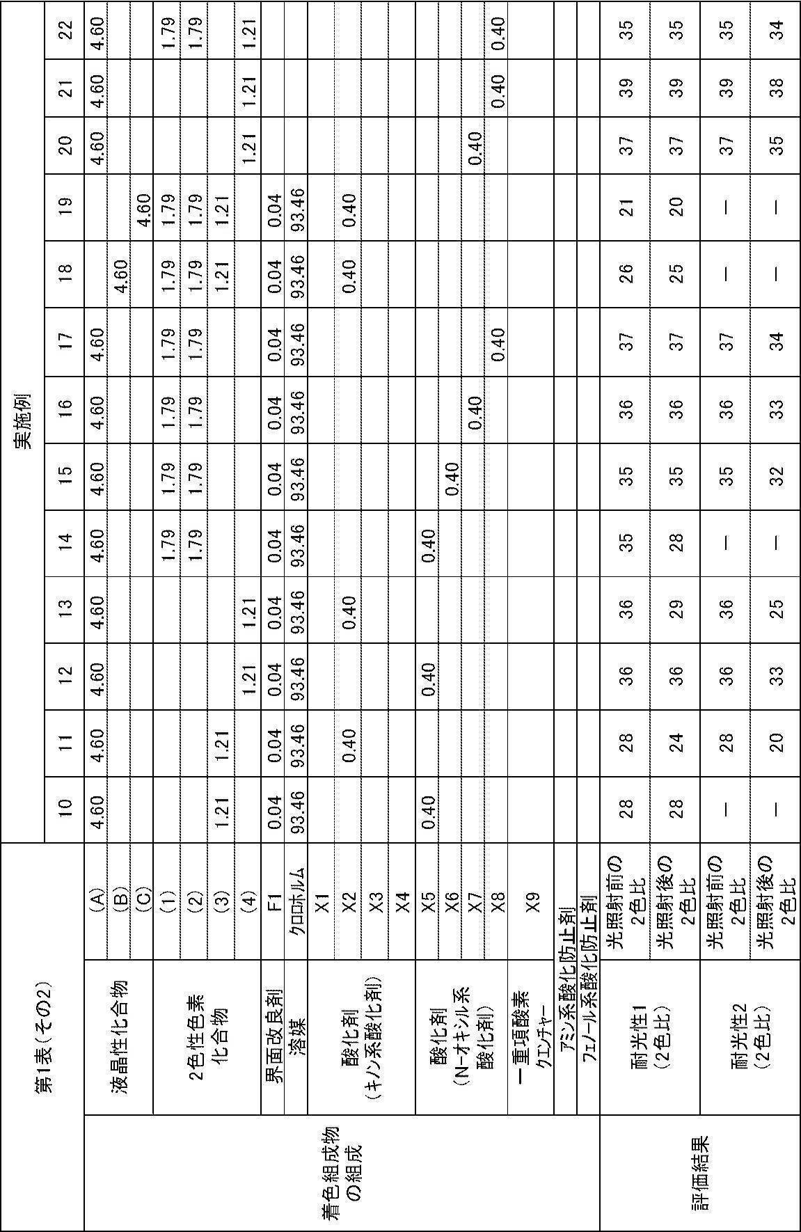

第1表における各成分の詳細は、以下の通りである。
液晶性化合物(A):下記式(A)で表される化合物
液晶性化合物(B):下記式(B)で表される化合物
液晶性化合物(C):下記式(C)で表される化合物
液晶性化合物(B):下記式(B)で表される化合物
液晶性化合物(C):下記式(C)で表される化合物

2色性色素化合物(1):下記式(1)で表される化合物
2色性色素化合物(2):下記式(2)で表される化合物
2色性色素化合物(3):下記式(3)で表される化合物
2色性色素化合物(4):下記式(4)で表される化合物
2色性色素化合物(2):下記式(2)で表される化合物
2色性色素化合物(3):下記式(3)で表される化合物
2色性色素化合物(4):下記式(4)で表される化合物

界面改良剤F1:下記式(F1)で表される化合物

溶媒:クロロホルム
X1:キノン系酸化剤(下記式(X1)で表される化合物)
X2:キノン系酸化剤(下記式(X2)で表される化合物)
X3:キノン系酸化剤(下記式(X3)で表される化合物)
X4:キノン系酸化剤(下記式(X4)で表される化合物)
X5:N-オキシル系酸化剤(下記式(X5)で表される化合物)
X6:N-オキシル系酸化剤(下記式(X6)で表される化合物)
X7:N-オキシル系酸化剤(下記式(X7)で表される化合物)
X8:N-オキシル系酸化剤(下記式(X8)で表される化合物)
X9:一重項酸素クエンチャー(下記式(X9)で表される化合物)
X2:キノン系酸化剤(下記式(X2)で表される化合物)
X3:キノン系酸化剤(下記式(X3)で表される化合物)
X4:キノン系酸化剤(下記式(X4)で表される化合物)
X5:N-オキシル系酸化剤(下記式(X5)で表される化合物)
X6:N-オキシル系酸化剤(下記式(X6)で表される化合物)
X7:N-オキシル系酸化剤(下記式(X7)で表される化合物)
X8:N-オキシル系酸化剤(下記式(X8)で表される化合物)
X9:一重項酸素クエンチャー(下記式(X9)で表される化合物)

アミン系酸化防止剤:2,2,6,6-テトラメチル-4-ピペリジル-C12-21およびC18不飽和脂肪酸エステル(商品名CYASORB UV3853,サンケミカル社製)
フェノール系酸化防止剤:2,6-ジ-tert-ブチル-p-クレゾール(BHT、東京化成工業社製)
フェノール系酸化防止剤:2,6-ジ-tert-ブチル-p-クレゾール(BHT、東京化成工業社製)
第1表に示すように、アゾ基を有する2色性色素化合物と、酸化剤または一重項酸素クエンチャーと、を含有する着色組成物を用いることで、耐光性に優れた光吸収異方性膜が得られることが示された(実施例)。
実施例1~3と実施例11および13との対比によれば、酸化剤としてキノン系酸化剤を用いた場合、上記式(D2)で表される部分構造を有する2色性色素化合物を用いると(実施例1~3)、上記式(D1)で表される部分構造を有する2色性色素化合物と用いる場合と比較して(実施例11および13)、耐光性が優れる(2色比の低下率が小さい)ことが示された。
実施例10と実施例14との対比によれば、酸化剤としてN-オキシル系酸化剤を用いた場合、上記式(D1)で表される部分構造を有する2色性色素化合物と用いると(実施例10)、上記式(D2)で表される部分構造を有する2色性色素化合物と用いる場合と比較して(実施例14)、耐光性が優れる(2色比の低下率が小さい)ことが示された。
一方、比較例1~4、7および8の光吸収異方性膜は、酸化剤および一重項酸素クエンチャーを含有しない着色組成物を用いて形成されたため、耐光性試験後の2色比が著しく低下して、耐光性が悪化することが示された。
また、比較例5~6の光吸収異方性膜は、各種酸化防止剤を含有するものの、酸化剤および一重項酸素クエンチャーを含有しない着色組成物を用いて形成されたため、耐光性試験後の2色比が著しく低下して、耐光性が悪化することが示された。
実施例1~3と実施例11および13との対比によれば、酸化剤としてキノン系酸化剤を用いた場合、上記式(D2)で表される部分構造を有する2色性色素化合物を用いると(実施例1~3)、上記式(D1)で表される部分構造を有する2色性色素化合物と用いる場合と比較して(実施例11および13)、耐光性が優れる(2色比の低下率が小さい)ことが示された。
実施例10と実施例14との対比によれば、酸化剤としてN-オキシル系酸化剤を用いた場合、上記式(D1)で表される部分構造を有する2色性色素化合物と用いると(実施例10)、上記式(D2)で表される部分構造を有する2色性色素化合物と用いる場合と比較して(実施例14)、耐光性が優れる(2色比の低下率が小さい)ことが示された。
一方、比較例1~4、7および8の光吸収異方性膜は、酸化剤および一重項酸素クエンチャーを含有しない着色組成物を用いて形成されたため、耐光性試験後の2色比が著しく低下して、耐光性が悪化することが示された。
また、比較例5~6の光吸収異方性膜は、各種酸化防止剤を含有するものの、酸化剤および一重項酸素クエンチャーを含有しない着色組成物を用いて形成されたため、耐光性試験後の2色比が著しく低下して、耐光性が悪化することが示された。
[実施例23]
以下のようにして作製した配向膜2上に、後述する実施例23の着色組成物を用いて光吸収異方性膜を作製した。
以下のようにして作製した配向膜2上に、後述する実施例23の着色組成物を用いて光吸収異方性膜を作製した。
<配向膜2の作製>
透明基材フィルム(富士フイルム社製、セルロースアシレート系フィルム、商品名「フジタック TG40UL」)を準備して、ケン化処理により表面を親水化した後、下記の配向膜形成用組成物2を#12のバーを用いて透明基材フィルム上に塗布し、塗布した配向膜形成用組成物2を110℃で2分間乾燥することにより、透明基材フィルム上に配向膜2を形成した。
透明基材フィルム(富士フイルム社製、セルロースアシレート系フィルム、商品名「フジタック TG40UL」)を準備して、ケン化処理により表面を親水化した後、下記の配向膜形成用組成物2を#12のバーを用いて透明基材フィルム上に塗布し、塗布した配向膜形成用組成物2を110℃で2分間乾燥することにより、透明基材フィルム上に配向膜2を形成した。
―――――――――――――――――――――――――――――――――
配向膜形成用組成物2の組成
―――――――――――――――――――――――――――――――――
・変性ビニルアルコール(上記式(PVA-1)) 2.00質量部
・水 74.08質量部
・メタノール 23.76質量部
・光重合開始剤
(イルガキュア2959、BASF社製) 0.06質量部
―――――――――――――――――――――――――――――――――
配向膜形成用組成物2の組成
―――――――――――――――――――――――――――――――――
・変性ビニルアルコール(上記式(PVA-1)) 2.00質量部
・水 74.08質量部
・メタノール 23.76質量部
・光重合開始剤
(イルガキュア2959、BASF社製) 0.06質量部
―――――――――――――――――――――――――――――――――
<光吸収異方性膜の作製>
得られた配向膜2上に、実施例23の着色組成物(下記組成を参照)を、スピンコーターを用いて、回転速度1000回転/30秒の条件でスピンコートした後、室温で30秒間乾燥させることで、配向膜2上に塗布膜を形成した。続いて、得られた塗布膜を140℃で30秒間加熱した後、塗布膜が室温なるまで冷却した。次いで、塗布膜を80℃まで再加熱して30秒間保持した後、塗布膜を室温まで冷却した。このようにして、配向膜2上に実施例23の光吸収異方性膜を作製した。
得られた配向膜2上に、実施例23の着色組成物(下記組成を参照)を、スピンコーターを用いて、回転速度1000回転/30秒の条件でスピンコートした後、室温で30秒間乾燥させることで、配向膜2上に塗布膜を形成した。続いて、得られた塗布膜を140℃で30秒間加熱した後、塗布膜が室温なるまで冷却した。次いで、塗布膜を80℃まで再加熱して30秒間保持した後、塗布膜を室温まで冷却した。このようにして、配向膜2上に実施例23の光吸収異方性膜を作製した。
―――――――――――――――――――――――――――――――――
実施例23の着色組成物の組成
―――――――――――――――――――――――――――――――――
・2色性色素化合物(5)(下記式(5)参照) 9.63質量部
・2色性色素化合物(4)(上記式(4)) 7.92質量部
・液晶性化合物P(下記式(P)参照) 40.11質量部
・界面改良剤F2(下記式(F2)参照) 0.73質量部
・界面改良剤F3(下記式(F3)参照) 0.73質量部
・界面改良剤F4(下記式(F4)参照) 0.87質量部
・テトラヒドロフラン(溶媒) 799.0質量部
・シクロペンタノン(溶媒) 141.0質量部
・酸化剤(X-5)(上記式(X-5)参照) 0.87質量部
―――――――――――――――――――――――――――――――――
実施例23の着色組成物の組成
―――――――――――――――――――――――――――――――――
・2色性色素化合物(5)(下記式(5)参照) 9.63質量部
・2色性色素化合物(4)(上記式(4)) 7.92質量部
・液晶性化合物P(下記式(P)参照) 40.11質量部
・界面改良剤F2(下記式(F2)参照) 0.73質量部
・界面改良剤F3(下記式(F3)参照) 0.73質量部
・界面改良剤F4(下記式(F4)参照) 0.87質量部
・テトラヒドロフラン(溶媒) 799.0質量部
・シクロペンタノン(溶媒) 141.0質量部
・酸化剤(X-5)(上記式(X-5)参照) 0.87質量部
―――――――――――――――――――――――――――――――――

<光吸収異方性膜の耐光性>
実施例23の光吸収異方性膜の耐光性1について、実施例1~22と同様にして測定したところ、光照射前後の2色比がいずれも31であった。
このように、アゾ基を有する2色性色素化合物と、酸化剤とを含有する着色組成物を用いることで、耐光性に優れた光吸収異方性膜が得られることが示された。
実施例23の光吸収異方性膜の耐光性1について、実施例1~22と同様にして測定したところ、光照射前後の2色比がいずれも31であった。
このように、アゾ基を有する2色性色素化合物と、酸化剤とを含有する着色組成物を用いることで、耐光性に優れた光吸収異方性膜が得られることが示された。
Claims (12)
- アゾ基を有する2色性色素化合物と、酸化剤と、を含有する、着色組成物。
- 前記酸化剤が、キノン構造およびN-オキシル構造の少なくとも一方の構造を有する、請求項1に記載の着色組成物。
- 前記アゾ基を有する2色性色素化合物が、下記式(D1)で表される部分構造を有し、
前記酸化剤が、N-オキシル構造を有する、請求項1または2に記載の着色組成物。

前記式(D1)中、Ar1およびAr2はそれぞれ独立に、芳香族炭化水素環または複素環を表し、nは1、3または4の整数を表し、*は他の基との結合位置を表す。nが3または4である場合、複数のAr2は互いに同一でも異なっていてもよい。ただし、前記式(D1)の両末端に位置するAr1およびAr2において、他の基との結合位置*における結合手はいずれも、アゾ基と直接結合することはない。 - 前記N-オキシル構造が、下記式(N1)で表される構造、または、下記式(N2)で表される構造である、請求項2または3に記載の着色組成物。

前記式(N1)中、R21~R28はそれぞれ独立に、水素原子または置換基を表す。R21~R28からなる群より選択される2個以上の基が置換基である場合、2個以上の置換基同士が互いに連結して環を形成してもよい。
前記式(N2)中、R31~R40はそれぞれ独立に、水素原子または置換基を表す。R31~R40からなる群より選択される2個以上の基が置換基である場合、2個以上の置換基同士が互いに連結して環を形成してもよい。 - 前記アゾ基を有する2色性色素化合物が、下記式(D2)で表される部分構造を有し、
前記酸化剤が、キノン構造を有する、請求項1または2に記載の着色組成物。

- アゾ基を有する2色性色素化合物と、一重項酸素クエンチャーと、を含有する、着色組成物。
- 前記一重項酸素クエンチャーが、ジインモニウム塩化合物である、請求項6に記載の着色組成物。
- さらに、液晶性化合物を含有する、請求項1~7のいずれか1項に記載の着色組成物。
- 請求項1~8のいずれか1項に記載の着色組成物を用いて形成される、光吸収異方性膜。
- 基材と、前記基材上に形成された請求項9に記載の光吸収異方性膜と、を有する、積層体。
- さらに、前記光吸収異方性膜上に形成されたλ/4板を有する、請求項10に記載の積層体。
- 請求項9に記載の光吸収異方性膜、または、請求項10もしくは請求項11に記載の積層体を有する、画像表示装置。
Priority Applications (2)
| Application Number | Priority Date | Filing Date | Title |
|---|---|---|---|
| JP2018509120A JP6698821B2 (ja) | 2016-03-31 | 2017-03-22 | 着色組成物、光吸収異方性膜、積層体および画像表示装置 |
| US16/145,910 US20190101676A1 (en) | 2016-03-31 | 2018-09-28 | Coloring composition, light absorption anisotropic film, laminate, and image display device |
Applications Claiming Priority (4)
| Application Number | Priority Date | Filing Date | Title |
|---|---|---|---|
| JP2016071172 | 2016-03-31 | ||
| JP2016-071172 | 2016-03-31 | ||
| JP2017045320 | 2017-03-09 | ||
| JP2017-045320 | 2017-03-09 |
Related Child Applications (1)
| Application Number | Title | Priority Date | Filing Date |
|---|---|---|---|
| US16/145,910 Continuation US20190101676A1 (en) | 2016-03-31 | 2018-09-28 | Coloring composition, light absorption anisotropic film, laminate, and image display device |
Publications (1)
| Publication Number | Publication Date |
|---|---|
| WO2017170036A1 true WO2017170036A1 (ja) | 2017-10-05 |
Family
ID=59965383
Family Applications (1)
| Application Number | Title | Priority Date | Filing Date |
|---|---|---|---|
| PCT/JP2017/011442 Ceased WO2017170036A1 (ja) | 2016-03-31 | 2017-03-22 | 着色組成物、光吸収異方性膜、積層体および画像表示装置 |
Country Status (3)
| Country | Link |
|---|---|
| US (1) | US20190101676A1 (ja) |
| JP (2) | JP6698821B2 (ja) |
| WO (1) | WO2017170036A1 (ja) |
Cited By (17)
| Publication number | Priority date | Publication date | Assignee | Title |
|---|---|---|---|---|
| WO2019131943A1 (ja) * | 2017-12-28 | 2019-07-04 | 富士フイルム株式会社 | 光学積層体の製造方法、光学積層体および画像表示装置 |
| WO2019221123A1 (ja) * | 2018-05-14 | 2019-11-21 | 富士フイルム株式会社 | 光学積層体の製造方法、表示装置の製造方法 |
| JPWO2018124198A1 (ja) * | 2016-12-28 | 2019-11-21 | 富士フイルム株式会社 | 液晶性組成物、高分子液晶化合物、光吸収異方性膜、積層体および画像表示装置 |
| WO2020003938A1 (ja) * | 2018-06-27 | 2020-01-02 | 富士フイルム株式会社 | 偏光子、及び、画像表示装置 |
| WO2020004303A1 (ja) * | 2018-06-27 | 2020-01-02 | 富士フイルム株式会社 | 偏光子、および、画像表示装置 |
| JPWO2018186503A1 (ja) * | 2017-04-07 | 2020-02-06 | 富士フイルム株式会社 | 異方性光吸収膜および積層体 |
| JP2020032759A (ja) * | 2018-08-27 | 2020-03-05 | 株式会社小糸製作所 | 車両用の樹脂製複合モジュールの製造方法 |
| JP6695014B1 (ja) * | 2018-11-12 | 2020-05-20 | 日東電工株式会社 | 偏光膜、偏光フィルム、積層偏光フィルム、画像表示パネル、および画像表示装置、ならびに偏光膜の製造方法 |
| JP6697646B1 (ja) * | 2018-11-12 | 2020-05-20 | 日東電工株式会社 | 偏光フィルム、積層偏光フィルム、画像表示パネル、および画像表示装置 |
| WO2020100880A1 (ja) * | 2018-11-12 | 2020-05-22 | 日東電工株式会社 | 偏光膜、偏光フィルム、積層偏光フィルム、画像表示パネル、および画像表示装置、ならびに偏光膜の製造方法 |
| WO2020100845A1 (ja) * | 2018-11-12 | 2020-05-22 | 日東電工株式会社 | 偏光フィルム、積層偏光フィルム、画像表示パネル、および画像表示装置 |
| JPWO2019132020A1 (ja) * | 2017-12-28 | 2020-07-16 | 富士フイルム株式会社 | 偏光子、及び、画像表示装置 |
| JPWO2019132018A1 (ja) * | 2017-12-28 | 2020-07-27 | 富士フイルム株式会社 | 偏光子、及び、画像表示装置 |
| JPWO2019225468A1 (ja) * | 2018-05-25 | 2021-06-17 | 富士フイルム株式会社 | 偏光子および画像表示装置 |
| CN113661422A (zh) * | 2019-04-12 | 2021-11-16 | 富士胶片株式会社 | 偏振器及图像显示装置 |
| JP2022064940A (ja) * | 2018-04-27 | 2022-04-26 | 富士フイルム株式会社 | 光吸収異方性膜、積層体、積層体の製造方法および画像表示装置 |
| WO2024043149A1 (ja) * | 2022-08-23 | 2024-02-29 | 富士フイルム株式会社 | 光吸収異方性膜、光学フィルム及び表示装置 |
Citations (5)
| Publication number | Priority date | Publication date | Assignee | Title |
|---|---|---|---|---|
| JPH11151861A (ja) * | 1997-11-21 | 1999-06-08 | Nippon Kayaku Co Ltd | 光情報記録媒体 |
| JPH11508937A (ja) * | 1995-07-13 | 1999-08-03 | ゼネカ・リミテッド | 安定化された染料組成物 |
| WO2003004515A1 (en) * | 2001-07-06 | 2003-01-16 | Chugai Seiyaku Kabushiki Kaisha | Process for production of estradiol derivatives, intermediates used in the process and process for production thereof |
| JP2011237513A (ja) * | 2010-05-07 | 2011-11-24 | Fujifilm Corp | 光吸収異方性膜、その製造方法、及びそれを用いた液晶表示装置 |
| JP2012063387A (ja) * | 2010-09-14 | 2012-03-29 | Sumitomo Chemical Co Ltd | 重合性液晶組成物及び光学フィルム |
Family Cites Families (5)
| Publication number | Priority date | Publication date | Assignee | Title |
|---|---|---|---|---|
| JPS6440380A (en) * | 1987-08-06 | 1989-02-10 | Canon Kk | Data recording medium |
| JP4276877B2 (ja) * | 2003-04-22 | 2009-06-10 | 富士フイルム株式会社 | 光情報記録媒体および色素 |
| JP4327668B2 (ja) * | 2004-06-25 | 2009-09-09 | 太陽誘電株式会社 | 光情報記録媒体 |
| JP5016265B2 (ja) * | 2006-06-27 | 2012-09-05 | パナソニック株式会社 | メタクリル樹脂組成物 |
| JP6728581B2 (ja) * | 2014-06-25 | 2020-07-22 | 住友化学株式会社 | 光吸収異方性膜、3次元光吸収異方性膜及びその製造方法 |
-
2017
- 2017-03-22 WO PCT/JP2017/011442 patent/WO2017170036A1/ja not_active Ceased
- 2017-03-22 JP JP2018509120A patent/JP6698821B2/ja active Active
-
2018
- 2018-09-28 US US16/145,910 patent/US20190101676A1/en not_active Abandoned
-
2020
- 2020-04-24 JP JP2020077596A patent/JP7080274B2/ja active Active
Patent Citations (5)
| Publication number | Priority date | Publication date | Assignee | Title |
|---|---|---|---|---|
| JPH11508937A (ja) * | 1995-07-13 | 1999-08-03 | ゼネカ・リミテッド | 安定化された染料組成物 |
| JPH11151861A (ja) * | 1997-11-21 | 1999-06-08 | Nippon Kayaku Co Ltd | 光情報記録媒体 |
| WO2003004515A1 (en) * | 2001-07-06 | 2003-01-16 | Chugai Seiyaku Kabushiki Kaisha | Process for production of estradiol derivatives, intermediates used in the process and process for production thereof |
| JP2011237513A (ja) * | 2010-05-07 | 2011-11-24 | Fujifilm Corp | 光吸収異方性膜、その製造方法、及びそれを用いた液晶表示装置 |
| JP2012063387A (ja) * | 2010-09-14 | 2012-03-29 | Sumitomo Chemical Co Ltd | 重合性液晶組成物及び光学フィルム |
Cited By (59)
| Publication number | Priority date | Publication date | Assignee | Title |
|---|---|---|---|---|
| JPWO2018124198A1 (ja) * | 2016-12-28 | 2019-11-21 | 富士フイルム株式会社 | 液晶性組成物、高分子液晶化合物、光吸収異方性膜、積層体および画像表示装置 |
| US11505744B2 (en) | 2016-12-28 | 2022-11-22 | Fujifilm Corporation | Liquid crystalline composition, polymer liquid crystal compound, light absorption anisotropic film, laminate, and image display device |
| JPWO2018186503A1 (ja) * | 2017-04-07 | 2020-02-06 | 富士フイルム株式会社 | 異方性光吸収膜および積層体 |
| US12085742B2 (en) | 2017-04-07 | 2024-09-10 | Fujifilm Corporation | Anisotropic light absorption film and laminate |
| CN111527424B (zh) * | 2017-12-28 | 2022-11-29 | 富士胶片株式会社 | 光学层叠体的制造方法、光学层叠体及图像显示装置 |
| JPWO2019131943A1 (ja) * | 2017-12-28 | 2021-01-07 | 富士フイルム株式会社 | 光学積層体の製造方法、光学積層体および画像表示装置 |
| US11378838B2 (en) | 2017-12-28 | 2022-07-05 | Fujifilm Corporation | Method for manufacturing optical laminate, optical laminate, and image display device |
| KR102834140B1 (ko) * | 2017-12-28 | 2025-07-15 | 후지필름 가부시키가이샤 | 광학 적층체의 제조 방법, 광학 적층체 및 화상 표시 장치 |
| JP7559008B2 (ja) | 2017-12-28 | 2024-10-01 | 富士フイルム株式会社 | 光学積層体の製造方法、光学積層体および画像表示装置 |
| JP2022120853A (ja) * | 2017-12-28 | 2022-08-18 | 富士フイルム株式会社 | 光学積層体の製造方法、光学積層体および画像表示装置 |
| US11339329B2 (en) | 2017-12-28 | 2022-05-24 | Fujifilm Corporation | Polarizer and image display device |
| US11467442B2 (en) | 2017-12-28 | 2022-10-11 | Fujifilm Corporation | Polarizer and image display device |
| JPWO2019132020A1 (ja) * | 2017-12-28 | 2020-07-16 | 富士フイルム株式会社 | 偏光子、及び、画像表示装置 |
| JPWO2019132018A1 (ja) * | 2017-12-28 | 2020-07-27 | 富士フイルム株式会社 | 偏光子、及び、画像表示装置 |
| WO2019131943A1 (ja) * | 2017-12-28 | 2019-07-04 | 富士フイルム株式会社 | 光学積層体の製造方法、光学積層体および画像表示装置 |
| CN111527424A (zh) * | 2017-12-28 | 2020-08-11 | 富士胶片株式会社 | 光学层叠体的制造方法、光学层叠体及图像显示装置 |
| CN111527426A (zh) * | 2017-12-28 | 2020-08-11 | 富士胶片株式会社 | 偏振器及图像显示装置 |
| US11822180B2 (en) | 2017-12-28 | 2023-11-21 | Fujifilm Corporation | Polarizer and image display device |
| JP7109476B2 (ja) | 2017-12-28 | 2022-07-29 | 富士フイルム株式会社 | 光学積層体の製造方法、光学積層体および画像表示装置 |
| KR20230152785A (ko) * | 2017-12-28 | 2023-11-03 | 후지필름 가부시키가이샤 | 광학 적층체의 제조 방법, 광학 적층체 및 화상 표시 장치 |
| JP2022064940A (ja) * | 2018-04-27 | 2022-04-26 | 富士フイルム株式会社 | 光吸収異方性膜、積層体、積層体の製造方法および画像表示装置 |
| JP7404411B2 (ja) | 2018-04-27 | 2023-12-25 | 富士フイルム株式会社 | 光吸収異方性膜、積層体、積層体の製造方法および画像表示装置 |
| WO2019221123A1 (ja) * | 2018-05-14 | 2019-11-21 | 富士フイルム株式会社 | 光学積層体の製造方法、表示装置の製造方法 |
| JPWO2019221123A1 (ja) * | 2018-05-14 | 2021-05-13 | 富士フイルム株式会社 | 光学積層体の製造方法、表示装置の製造方法 |
| JP7016412B2 (ja) | 2018-05-14 | 2022-02-04 | 富士フイルム株式会社 | 光学積層体の製造方法、表示装置の製造方法 |
| JPWO2019225468A1 (ja) * | 2018-05-25 | 2021-06-17 | 富士フイルム株式会社 | 偏光子および画像表示装置 |
| JP7029529B2 (ja) | 2018-05-25 | 2022-03-03 | 富士フイルム株式会社 | 偏光子および画像表示装置 |
| JP2022068164A (ja) * | 2018-05-25 | 2022-05-09 | 富士フイルム株式会社 | 偏光子および画像表示装置 |
| JP7291814B2 (ja) | 2018-05-25 | 2023-06-15 | 富士フイルム株式会社 | 偏光子および画像表示装置 |
| JPWO2020004303A1 (ja) * | 2018-06-27 | 2021-06-24 | 富士フイルム株式会社 | 偏光子、および、画像表示装置 |
| WO2020003938A1 (ja) * | 2018-06-27 | 2020-01-02 | 富士フイルム株式会社 | 偏光子、及び、画像表示装置 |
| JP7169352B2 (ja) | 2018-06-27 | 2022-11-10 | 富士フイルム株式会社 | 偏光子、および、画像表示装置 |
| US11543697B2 (en) | 2018-06-27 | 2023-01-03 | Fujifilm Corporation | Polarizer and image display device |
| JPWO2020003938A1 (ja) * | 2018-06-27 | 2021-07-08 | 富士フイルム株式会社 | 偏光子、及び、画像表示装置 |
| WO2020004303A1 (ja) * | 2018-06-27 | 2020-01-02 | 富士フイルム株式会社 | 偏光子、および、画像表示装置 |
| JP7231627B2 (ja) | 2018-06-27 | 2023-03-01 | 富士フイルム株式会社 | 偏光子、及び、画像表示装置 |
| JP2020032759A (ja) * | 2018-08-27 | 2020-03-05 | 株式会社小糸製作所 | 車両用の樹脂製複合モジュールの製造方法 |
| JP2020129122A (ja) * | 2018-11-12 | 2020-08-27 | 日東電工株式会社 | 偏光膜、偏光フィルム、積層偏光フィルム、画像表示パネル、および画像表示装置、ならびに偏光膜の製造方法 |
| CN112042268A (zh) * | 2018-11-12 | 2020-12-04 | 日东电工株式会社 | 偏光膜、偏振膜、层叠偏振膜、图像显示面板及图像显示装置、以及偏光膜的制造方法 |
| CN114966935A (zh) * | 2018-11-12 | 2022-08-30 | 日东电工株式会社 | 偏振膜、层叠偏振膜、图像显示面板、以及图像显示装置 |
| WO2020100845A1 (ja) * | 2018-11-12 | 2020-05-22 | 日東電工株式会社 | 偏光フィルム、積層偏光フィルム、画像表示パネル、および画像表示装置 |
| JP7405683B2 (ja) | 2018-11-12 | 2023-12-26 | 日東電工株式会社 | 偏光フィルム、積層偏光フィルム、画像表示パネル、および画像表示装置 |
| KR102337430B1 (ko) * | 2018-11-12 | 2021-12-09 | 닛토덴코 가부시키가이샤 | 편광막, 편광 필름, 적층 편광 필름, 화상 표시 패널 및 화상 표시 장치, 및 편광막의 제조 방법 |
| CN111837061B (zh) * | 2018-11-12 | 2022-05-27 | 日东电工株式会社 | 偏振膜、层叠偏振膜、图像显示面板、以及图像显示装置 |
| CN112042268B (zh) * | 2018-11-12 | 2021-08-10 | 日东电工株式会社 | 偏光膜、偏振膜、层叠偏振膜、图像显示面板及图像显示装置、以及偏光膜的制造方法 |
| KR20210019403A (ko) * | 2018-11-12 | 2021-02-22 | 닛토덴코 가부시키가이샤 | 편광막, 편광 필름, 적층 편광 필름, 화상 표시 패널 및 화상 표시 장치, 및 편광막의 제조 방법 |
| WO2020100880A1 (ja) * | 2018-11-12 | 2020-05-22 | 日東電工株式会社 | 偏光膜、偏光フィルム、積層偏光フィルム、画像表示パネル、および画像表示装置、ならびに偏光膜の製造方法 |
| CN111837061A (zh) * | 2018-11-12 | 2020-10-27 | 日东电工株式会社 | 偏振膜、层叠偏振膜、图像显示面板、以及图像显示装置 |
| JP2020126264A (ja) * | 2018-11-12 | 2020-08-20 | 日東電工株式会社 | 偏光フィルム、積層偏光フィルム、画像表示パネル、および画像表示装置 |
| JP6732157B1 (ja) * | 2018-11-12 | 2020-07-29 | 日東電工株式会社 | 偏光フィルム、積層偏光フィルム、画像表示パネル、および画像表示装置 |
| WO2020100887A1 (ja) * | 2018-11-12 | 2020-05-22 | 日東電工株式会社 | 偏光膜、偏光フィルム、積層偏光フィルム、画像表示パネル、および画像表示装置、ならびに偏光膜の製造方法 |
| TWI828795B (zh) * | 2018-11-12 | 2024-01-11 | 日商日東電工股份有限公司 | 偏光膜、偏光薄膜、積層偏光薄膜、影像顯示面板及影像顯示裝置、以及偏光膜之製造方法 |
| TWI828794B (zh) * | 2018-11-12 | 2024-01-11 | 日商日東電工股份有限公司 | 偏光膜、偏光薄膜、積層偏光薄膜、影像顯示面板及影像顯示裝置、以及偏光膜之製造方法 |
| JP6695014B1 (ja) * | 2018-11-12 | 2020-05-20 | 日東電工株式会社 | 偏光膜、偏光フィルム、積層偏光フィルム、画像表示パネル、および画像表示装置、ならびに偏光膜の製造方法 |
| JP6697646B1 (ja) * | 2018-11-12 | 2020-05-20 | 日東電工株式会社 | 偏光フィルム、積層偏光フィルム、画像表示パネル、および画像表示装置 |
| CN113661422A (zh) * | 2019-04-12 | 2021-11-16 | 富士胶片株式会社 | 偏振器及图像显示装置 |
| CN113661422B (zh) * | 2019-04-12 | 2024-06-04 | 富士胶片株式会社 | 偏振器及图像显示装置 |
| US12152188B2 (en) | 2019-04-12 | 2024-11-26 | Fujifilm Corporation | Polarizer and image display device |
| WO2024043149A1 (ja) * | 2022-08-23 | 2024-02-29 | 富士フイルム株式会社 | 光吸収異方性膜、光学フィルム及び表示装置 |
Also Published As
| Publication number | Publication date |
|---|---|
| US20190101676A1 (en) | 2019-04-04 |
| JP2020125486A (ja) | 2020-08-20 |
| JPWO2017170036A1 (ja) | 2019-02-28 |
| JP7080274B2 (ja) | 2022-06-03 |
| JP6698821B2 (ja) | 2020-05-27 |
Similar Documents
| Publication | Publication Date | Title |
|---|---|---|
| JP7080274B2 (ja) | 着色組成物、光吸収異方性膜、積層体および画像表示装置 | |
| JP7560624B2 (ja) | 組成物、二色性物質、光吸収異方性膜、積層体および画像表示装置 | |
| JP6616489B2 (ja) | 着色組成物、光吸収異方性膜、積層体および画像表示装置 | |
| JP6896890B2 (ja) | 光吸収異方性膜、光学積層体および画像表示装置 | |
| JP2022064940A (ja) | 光吸収異方性膜、積層体、積層体の製造方法および画像表示装置 | |
| JP6811846B2 (ja) | 偏光素子、円偏光板および画像表示装置 | |
| WO2017195833A1 (ja) | 着色組成物、2色性色素化合物、光吸収異方性膜、積層体および画像表示装置 | |
| CN115698788B (zh) | 光吸收各向异性膜、层叠体及图像显示装置 | |
| KR102278303B1 (ko) | 착색 조성물, 2색성 색소 화합물, 광흡수 이방성막, 적층체 및 화상 표시 장치 | |
| CN113227850B (zh) | 吸光各向异性膜、层叠体及图像显示装置 | |
| JP7457739B2 (ja) | 偏光素子、円偏光板および画像表示装置 | |
| WO2019225468A1 (ja) | 偏光子および画像表示装置 | |
| JPWO2019131949A1 (ja) | 積層体、積層体の製造方法および画像表示装置 | |
| JP7062770B2 (ja) | 積層体および画像表示装置 | |
| JP2018053167A (ja) | 二色性色素化合物、着色組成物、光吸収異方性膜、積層体および画像表示装置 | |
| JP7014796B2 (ja) | 積層体、積層体の製造方法および画像表示装置 | |
| JP5451261B2 (ja) | 二色性色素組成物、これを用いた光吸収異方性膜、偏光素子及び液晶表示装置 | |
| WO2019182133A1 (ja) | 偏光子、偏光子の製造方法、積層体および画像表示装置 | |
| KR102782485B1 (ko) | 액정 조성물, 광흡수 이방성막, 적층체 및 화상 표시 장치 | |
| JP7690495B2 (ja) | 光吸収異方性膜、光学フィルムおよび液晶表示装置 | |
| JPWO2014168258A1 (ja) | 光学異方性フィルムの製造方法 | |
| WO2022168851A1 (ja) | 液晶組成物、硬化膜、偏光板、画像表示装置 | |
| JP2023139730A (ja) | 光学積層体および画像表示装置 |
Legal Events
| Date | Code | Title | Description |
|---|---|---|---|
| WWE | Wipo information: entry into national phase |
Ref document number: 2018509120 Country of ref document: JP |
|
| NENP | Non-entry into the national phase |
Ref country code: DE |
|
| 121 | Ep: the epo has been informed by wipo that ep was designated in this application |
Ref document number: 17774577 Country of ref document: EP Kind code of ref document: A1 |
|
| 122 | Ep: pct application non-entry in european phase |
Ref document number: 17774577 Country of ref document: EP Kind code of ref document: A1 |