WO2017170108A1 - Système de purification d'échappement - Google Patents
Système de purification d'échappement Download PDFInfo
- Publication number
- WO2017170108A1 WO2017170108A1 PCT/JP2017/011671 JP2017011671W WO2017170108A1 WO 2017170108 A1 WO2017170108 A1 WO 2017170108A1 JP 2017011671 W JP2017011671 W JP 2017011671W WO 2017170108 A1 WO2017170108 A1 WO 2017170108A1
- Authority
- WO
- WIPO (PCT)
- Prior art keywords
- exhaust
- injection nozzle
- pipe
- reducing agent
- exhaust gas
- Prior art date
- Legal status (The legal status is an assumption and is not a legal conclusion. Google has not performed a legal analysis and makes no representation as to the accuracy of the status listed.)
- Ceased
Links
Images


Classifications
-
- F—MECHANICAL ENGINEERING; LIGHTING; HEATING; WEAPONS; BLASTING
- F01—MACHINES OR ENGINES IN GENERAL; ENGINE PLANTS IN GENERAL; STEAM ENGINES
- F01N—GAS-FLOW SILENCERS OR EXHAUST APPARATUS FOR MACHINES OR ENGINES IN GENERAL; GAS-FLOW SILENCERS OR EXHAUST APPARATUS FOR INTERNAL-COMBUSTION ENGINES
- F01N3/00—Exhaust or silencing apparatus having means for purifying, rendering innocuous, or otherwise treating exhaust
- F01N3/08—Exhaust or silencing apparatus having means for purifying, rendering innocuous, or otherwise treating exhaust for rendering innocuous
- F01N3/10—Exhaust or silencing apparatus having means for purifying, rendering innocuous, or otherwise treating exhaust for rendering innocuous by thermal or catalytic conversion of noxious components of exhaust
- F01N3/18—Exhaust or silencing apparatus having means for purifying, rendering innocuous, or otherwise treating exhaust for rendering innocuous by thermal or catalytic conversion of noxious components of exhaust characterised by methods of operation; Control
- F01N3/20—Exhaust or silencing apparatus having means for purifying, rendering innocuous, or otherwise treating exhaust for rendering innocuous by thermal or catalytic conversion of noxious components of exhaust characterised by methods of operation; Control specially adapted for catalytic conversion
- F01N3/206—Adding periodically or continuously substances to exhaust gases for promoting purification, e.g. catalytic material in liquid form, NOx reducing agents
- F01N3/2066—Selective catalytic reduction [SCR]
- F01N3/2073—Means for generating a reducing substance from the exhaust gases
-
- B—PERFORMING OPERATIONS; TRANSPORTING
- B01—PHYSICAL OR CHEMICAL PROCESSES OR APPARATUS IN GENERAL
- B01D—SEPARATION
- B01D53/00—Separation of gases or vapours; Recovering vapours of volatile solvents from gases; Chemical or biological purification of waste gases, e.g. engine exhaust gases, smoke, fumes, flue gases, aerosols
- B01D53/34—Chemical or biological purification of waste gases
- B01D53/92—Chemical or biological purification of waste gases of engine exhaust gases
- B01D53/94—Chemical or biological purification of waste gases of engine exhaust gases by catalytic processes
-
- B—PERFORMING OPERATIONS; TRANSPORTING
- B01—PHYSICAL OR CHEMICAL PROCESSES OR APPARATUS IN GENERAL
- B01D—SEPARATION
- B01D53/00—Separation of gases or vapours; Recovering vapours of volatile solvents from gases; Chemical or biological purification of waste gases, e.g. engine exhaust gases, smoke, fumes, flue gases, aerosols
- B01D53/34—Chemical or biological purification of waste gases
- B01D53/92—Chemical or biological purification of waste gases of engine exhaust gases
- B01D53/94—Chemical or biological purification of waste gases of engine exhaust gases by catalytic processes
- B01D53/9404—Removing only nitrogen compounds
- B01D53/9409—Nitrogen oxides
- B01D53/9431—Processes characterised by a specific device
-
- B—PERFORMING OPERATIONS; TRANSPORTING
- B01—PHYSICAL OR CHEMICAL PROCESSES OR APPARATUS IN GENERAL
- B01F—MIXING, e.g. DISSOLVING, EMULSIFYING OR DISPERSING
- B01F23/00—Mixing according to the phases to be mixed, e.g. dispersing or emulsifying
- B01F23/20—Mixing gases with liquids
- B01F23/21—Mixing gases with liquids by introducing liquids into gaseous media
- B01F23/213—Mixing gases with liquids by introducing liquids into gaseous media by spraying or atomising of the liquids
- B01F23/2132—Mixing gases with liquids by introducing liquids into gaseous media by spraying or atomising of the liquids using nozzles
-
- B—PERFORMING OPERATIONS; TRANSPORTING
- B01—PHYSICAL OR CHEMICAL PROCESSES OR APPARATUS IN GENERAL
- B01F—MIXING, e.g. DISSOLVING, EMULSIFYING OR DISPERSING
- B01F25/00—Flow mixers; Mixers for falling materials, e.g. solid particles
- B01F25/30—Injector mixers
- B01F25/31—Injector mixers in conduits or tubes through which the main component flows
- B01F25/314—Injector mixers in conduits or tubes through which the main component flows wherein additional components are introduced at the circumference of the conduit
- B01F25/3141—Injector mixers in conduits or tubes through which the main component flows wherein additional components are introduced at the circumference of the conduit with additional mixing means other than injector mixers
-
- B—PERFORMING OPERATIONS; TRANSPORTING
- B01—PHYSICAL OR CHEMICAL PROCESSES OR APPARATUS IN GENERAL
- B01F—MIXING, e.g. DISSOLVING, EMULSIFYING OR DISPERSING
- B01F25/00—Flow mixers; Mixers for falling materials, e.g. solid particles
- B01F25/40—Static mixers
- B01F25/42—Static mixers in which the mixing is affected by moving the components jointly in changing directions, e.g. in tubes provided with baffles or obstructions
- B01F25/421—Static mixers in which the mixing is affected by moving the components jointly in changing directions, e.g. in tubes provided with baffles or obstructions by moving the components in a convoluted or labyrinthine path
- B01F25/423—Static mixers in which the mixing is affected by moving the components jointly in changing directions, e.g. in tubes provided with baffles or obstructions by moving the components in a convoluted or labyrinthine path by means of elements placed in the receptacle for moving or guiding the components
- B01F25/4231—Static mixers in which the mixing is affected by moving the components jointly in changing directions, e.g. in tubes provided with baffles or obstructions by moving the components in a convoluted or labyrinthine path by means of elements placed in the receptacle for moving or guiding the components using baffles
-
- F—MECHANICAL ENGINEERING; LIGHTING; HEATING; WEAPONS; BLASTING
- F01—MACHINES OR ENGINES IN GENERAL; ENGINE PLANTS IN GENERAL; STEAM ENGINES
- F01N—GAS-FLOW SILENCERS OR EXHAUST APPARATUS FOR MACHINES OR ENGINES IN GENERAL; GAS-FLOW SILENCERS OR EXHAUST APPARATUS FOR INTERNAL-COMBUSTION ENGINES
- F01N3/00—Exhaust or silencing apparatus having means for purifying, rendering innocuous, or otherwise treating exhaust
- F01N3/08—Exhaust or silencing apparatus having means for purifying, rendering innocuous, or otherwise treating exhaust for rendering innocuous
- F01N3/10—Exhaust or silencing apparatus having means for purifying, rendering innocuous, or otherwise treating exhaust for rendering innocuous by thermal or catalytic conversion of noxious components of exhaust
- F01N3/18—Exhaust or silencing apparatus having means for purifying, rendering innocuous, or otherwise treating exhaust for rendering innocuous by thermal or catalytic conversion of noxious components of exhaust characterised by methods of operation; Control
- F01N3/20—Exhaust or silencing apparatus having means for purifying, rendering innocuous, or otherwise treating exhaust for rendering innocuous by thermal or catalytic conversion of noxious components of exhaust characterised by methods of operation; Control specially adapted for catalytic conversion
- F01N3/206—Adding periodically or continuously substances to exhaust gases for promoting purification, e.g. catalytic material in liquid form, NOx reducing agents
- F01N3/208—Control of selective catalytic reduction [SCR], e.g. by adjusting the dosing of reducing agent
-
- F—MECHANICAL ENGINEERING; LIGHTING; HEATING; WEAPONS; BLASTING
- F01—MACHINES OR ENGINES IN GENERAL; ENGINE PLANTS IN GENERAL; STEAM ENGINES
- F01N—GAS-FLOW SILENCERS OR EXHAUST APPARATUS FOR MACHINES OR ENGINES IN GENERAL; GAS-FLOW SILENCERS OR EXHAUST APPARATUS FOR INTERNAL-COMBUSTION ENGINES
- F01N3/00—Exhaust or silencing apparatus having means for purifying, rendering innocuous, or otherwise treating exhaust
- F01N3/08—Exhaust or silencing apparatus having means for purifying, rendering innocuous, or otherwise treating exhaust for rendering innocuous
- F01N3/10—Exhaust or silencing apparatus having means for purifying, rendering innocuous, or otherwise treating exhaust for rendering innocuous by thermal or catalytic conversion of noxious components of exhaust
- F01N3/24—Exhaust or silencing apparatus having means for purifying, rendering innocuous, or otherwise treating exhaust for rendering innocuous by thermal or catalytic conversion of noxious components of exhaust characterised by constructional aspects of converting apparatus
- F01N3/28—Construction of catalytic reactors
- F01N3/2892—Exhaust flow directors or the like, e.g. upstream of catalytic device
-
- F—MECHANICAL ENGINEERING; LIGHTING; HEATING; WEAPONS; BLASTING
- F01—MACHINES OR ENGINES IN GENERAL; ENGINE PLANTS IN GENERAL; STEAM ENGINES
- F01N—GAS-FLOW SILENCERS OR EXHAUST APPARATUS FOR MACHINES OR ENGINES IN GENERAL; GAS-FLOW SILENCERS OR EXHAUST APPARATUS FOR INTERNAL-COMBUSTION ENGINES
- F01N2240/00—Combination or association of two or more different exhaust treating devices, or of at least one such device with an auxiliary device, not covered by indexing codes F01N2230/00 or F01N2250/00, one of the devices being
- F01N2240/20—Combination or association of two or more different exhaust treating devices, or of at least one such device with an auxiliary device, not covered by indexing codes F01N2230/00 or F01N2250/00, one of the devices being a flow director or deflector
-
- F—MECHANICAL ENGINEERING; LIGHTING; HEATING; WEAPONS; BLASTING
- F01—MACHINES OR ENGINES IN GENERAL; ENGINE PLANTS IN GENERAL; STEAM ENGINES
- F01N—GAS-FLOW SILENCERS OR EXHAUST APPARATUS FOR MACHINES OR ENGINES IN GENERAL; GAS-FLOW SILENCERS OR EXHAUST APPARATUS FOR INTERNAL-COMBUSTION ENGINES
- F01N2610/00—Adding substances to exhaust gases
- F01N2610/02—Adding substances to exhaust gases the substance being ammonia or urea
-
- F—MECHANICAL ENGINEERING; LIGHTING; HEATING; WEAPONS; BLASTING
- F01—MACHINES OR ENGINES IN GENERAL; ENGINE PLANTS IN GENERAL; STEAM ENGINES
- F01N—GAS-FLOW SILENCERS OR EXHAUST APPARATUS FOR MACHINES OR ENGINES IN GENERAL; GAS-FLOW SILENCERS OR EXHAUST APPARATUS FOR INTERNAL-COMBUSTION ENGINES
- F01N2610/00—Adding substances to exhaust gases
- F01N2610/14—Arrangements for the supply of substances, e.g. conduits
- F01N2610/1453—Sprayers or atomisers; Arrangement thereof in the exhaust apparatus
-
- Y—GENERAL TAGGING OF NEW TECHNOLOGICAL DEVELOPMENTS; GENERAL TAGGING OF CROSS-SECTIONAL TECHNOLOGIES SPANNING OVER SEVERAL SECTIONS OF THE IPC; TECHNICAL SUBJECTS COVERED BY FORMER USPC CROSS-REFERENCE ART COLLECTIONS [XRACs] AND DIGESTS
- Y02—TECHNOLOGIES OR APPLICATIONS FOR MITIGATION OR ADAPTATION AGAINST CLIMATE CHANGE
- Y02T—CLIMATE CHANGE MITIGATION TECHNOLOGIES RELATED TO TRANSPORTATION
- Y02T10/00—Road transport of goods or passengers
- Y02T10/10—Internal combustion engine [ICE] based vehicles
- Y02T10/12—Improving ICE efficiencies
Definitions
- the present disclosure relates to an exhaust purification system, and more particularly to an exhaust purification system including a reduction catalyst.
- an injection nozzle for adding urea water into an exhaust pipe and a nitrogen compound (hereinafter referred to as NOx) contained in exhaust gas using ammonia generated by hydrolysis from urea water by exhaust heat as a reducing agent.
- a selective reduction catalyst hereinafter referred to as an SCR catalyst for reducing and purifying.
- Patent Document 1 discloses a technique in which a reducing agent is efficiently mixed and diffused in exhaust gas by providing a mixer plate having a plurality of fins between a reducing agent injection nozzle and an SCR catalyst. It is disclosed.
- the mixer plate is disposed perpendicular to the pipe axis direction of the exhaust pipe, and urea water is injected into the exhaust pipe obliquely with respect to the pipe axis direction from the injection nozzle. For this reason, there is a problem that the urea water jetted obliquely in a substantially conical shape from the jet nozzle cannot collide with the entire surface of the plate, and in particular, the plate region that is far from the jet nozzle cannot be used efficiently.
- the disclosed system aims to effectively cause urea water (reducing agent) injected from the injection nozzle to collide with the entire mixer member.
- the disclosed system includes a linear exhaust pipe through which exhaust gas discharged from an engine flows, an injection nozzle that injects a reducing agent obliquely with respect to a pipe axis direction in the exhaust pipe, and a downstream side of the injection nozzle
- a reduction catalyst for purifying the exhaust gas by reacting with the reducing agent and a reduction catalyst provided in the exhaust pipe downstream of the injection nozzle and upstream of the reduction catalyst.
- the mixer member may be arranged to be inclined in the exhaust pipe so that the upstream side surface is perpendicular to the injection axis direction of the injection nozzle.
- the straight pipe is formed in a cylindrical shape
- the mixer member has an elliptical ring member whose outer periphery is fixed to the inner circumference of the straight pipe, and a plurality of flat plates arranged in a lattice in the ring member.
- a member and a plurality of fins formed integrally with the flat plate member and bent at a predetermined angle may be provided.
- the injection nozzle injects urea water into the straight pipe, and the reduction catalyst reduces and purifies nitrogen compounds contained in the exhaust gas using ammonia generated by hydrolysis from the urea water by exhaust heat as a reducing agent. It may be a selective reduction catalyst.
- urea water (reducing agent) injected from the injection nozzle can be effectively collided with the entire mixer member.
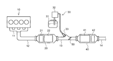
- FIG. 1 is a schematic overall configuration diagram illustrating an exhaust purification system according to an embodiment of the present disclosure.
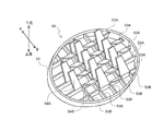
- FIG. 2 is a schematic perspective view illustrating a mixer member according to an embodiment of the present disclosure.
- FIG. 3 is a schematic cross-sectional view illustrating a main part of an exhaust purification system according to an embodiment of the present disclosure.
- FIG. 4 is a schematic cross-sectional view showing a main part of an exhaust purification system according to another embodiment.
- FIG. 5 is a schematic front view showing a mixer according to another embodiment.
- an exhaust system of a diesel engine (hereinafter simply referred to as an engine) 10 includes an exhaust manifold 11, an upstream pipe 12, a front casing 20, a straight pipe 13, and a rear casing in order from the exhaust upstream side. 40 and a discharge pipe 14.
- the upstream pipe 12 is formed in a substantially cylindrical shape, and its upstream end is connected to the exhaust manifold 11 and its downstream end is connected to the upstream opening of the front casing 20.
- the front casing 20 is formed in a substantially cylindrical shape, and a first oxidation catalyst 21 and a filter 22 are accommodated in that order from the exhaust upstream side.
- the first oxidation catalyst 21 is formed, for example, by carrying a catalyst component or the like on the surface of a ceramic carrier such as a cordierite honeycomb structure.
- a ceramic carrier such as a cordierite honeycomb structure.
- the filter 22 is formed, for example, by arranging a large number of cells partitioned by porous partition walls along the flow direction of the exhaust gas and alternately plugging the upstream side and the downstream side of these cells. .
- the filter 22 collects particulate matter (PM) in the exhaust gas in the pores and surfaces of the partition walls, and when the estimated amount of PM deposition reaches a predetermined amount, forced filter regeneration is performed to remove this.
- PM particulate matter
- the straight pipe 13 is formed in a substantially straight cylindrical shape, and connects the downstream opening of the front casing 20 and the upstream opening of the rear casing 40.
- the straight pipe 13 is provided with an injection nozzle 33 that constitutes a part of the urea water injection device 30, and a mixer plate 50, which will be described in detail later, is provided in the straight pipe 13 downstream of the injection nozzle 33. It has been.
- the urea water injection device 30 includes a urea water tank 31 that stores urea water, a urea water pump 32 that pumps urea water from the urea water tank 31, and an injection nozzle 33 that injects urea water into the straight pipe 13. Yes.
- the urea water injected from the injection nozzle 33 into the straight pipe 13 is hydrolyzed by exhaust heat to be generated into ammonia (NH 3 ), and is supplied to the SCR catalyst 41 on the downstream side as a reducing agent.
- NH 3 ammonia
- the rear casing 40 is formed in a substantially cylindrical shape, and an SCR catalyst 41 and a second oxidation catalyst 42 are accommodated in that order from the upstream side of the exhaust.
- the SCR catalyst 41 is formed, for example, by supporting zeolite or the like on a porous ceramic carrier.
- the SCR catalyst 41 adsorbs ammonia supplied as a reducing agent from the injection nozzle 33 and selectively reduces and purifies NOx from the exhaust gas passing through the adsorbed ammonia.
- the second oxidation catalyst 42 is formed, for example, by supporting a catalyst component or the like on the surface of a ceramic carrier such as a cordierite honeycomb structure, and has a function of oxidizing ammonia slipped downstream from the SCR catalyst 41. is doing.
- the mixer member 50 includes an elliptical ring member 51, a plurality of flat plate members 53 ⁇ / b> A and 53 ⁇ / b> B that are arranged in a lattice shape inside the ring member 51 to form an exhaust gas passage, A plurality of fins 54A and 54B that are integrally formed with the member 53A and project to the exhaust downstream side are provided.
- Each fin 54A, B is formed by making a substantially V-shaped cut into the flat plate member 53A and bending a portion left in a trapezoidal shape at a predetermined angle.
- Each fin 54A, B is formed such that fins 54A bent in one direction (A direction in the figure) and fins 54B bent in the other direction (B direction in the figure) are alternately arranged in parallel. Has been.
- the injection nozzle 33 is attached to the seat 13 ⁇ / b> A of the straight pipe 13 by a bolt or the like (not shown) so that the injection axis Y is inclined at a predetermined angle with respect to the pipe axis direction X of the straight pipe 13. It is fixed.
- the mixer member 50 has an upstream side surface 50A (a side surface opposite to the fins 54A and B) inclined with respect to the tube axis direction X and perpendicular to the injection axis Y.
- the outer periphery is fixed to the inner periphery of the straight pipe 13 by welding or the like.
- the upstream side surface 50A of the mixer member 50 does not have to be completely perpendicular to the injection axis Y of the injection nozzle 33, and may be inclined by about ⁇ 5 degrees.
- the mixer member 50 is attached in the straight pipe 13 so that the upstream side surface 50A faces the opening surface of the injection port 33A of the injection nozzle 33 substantially in parallel.
- urea water (reducing agent) injected in a substantially conical shape from the injection nozzle 33 uniformly collides with the entire surface of the upstream side surface 50A. It becomes like this.
- the mixer member 50 is attached to the straight pipe 13 so as to be inclined, and the upstream side surface 50 ⁇ / b> A is directly opposed to the injection port 33 ⁇ / b> A of the injection nozzle 33. Can be caused to collide uniformly with the entire surface of the upstream side surface 50A. This makes it possible to efficiently utilize the entire mixer member 50 to promote mixing and diffusion of the exhaust gas and the reducing agent, and to reliably improve the reduction efficiency of the SCR catalyst 41.
- ammonia (reducing agent) is uniformly distributed in the SCR catalyst 41, so that ammonia slip can be effectively suppressed, the capacity of the second oxidation catalyst 42 on the downstream side can be reduced, and the cost of the entire apparatus can be reduced. Reduction can be effectively achieved.
- the inclination angle of the mixer member 50 may be set more gently than in the above embodiment.
- the upstream side surface 50A of the mixer member 50 may be inclined in the exhaust pipe so as to be about 60 to about 85 degrees with respect to the injection axis Y of the injection nozzle 33.
- the adhesion of urea water to the fins 54A and 54B can be effectively promoted by setting the bending angle of each fin 54A and B to an acute angle as the distance from the injection nozzle 33 increases.
- the mechanism for mixing and diffusing the reducing agent and the exhaust gas is not limited to the mixer member 50, and includes a plurality of blades (fins) 62 provided radially around the hub 61 as shown in FIG.
- a mixer 60 can also be applied.
- the upstream side surface of the mixer 60 may be inclined so as to face the injection nozzle 33 (see FIG. 3).
- the engine 10 is not limited to a diesel engine, and can be widely applied to an internal combustion engine in addition to a gasoline engine or the like.
- the present invention has an effect that urea water (reducing agent) injected from the injection nozzle can be effectively collided with the entire mixer member, and is useful for an exhaust purification system and the like.
Landscapes
- Chemical & Material Sciences (AREA)
- Engineering & Computer Science (AREA)
- Chemical Kinetics & Catalysis (AREA)
- Health & Medical Sciences (AREA)
- Combustion & Propulsion (AREA)
- Toxicology (AREA)
- Mechanical Engineering (AREA)
- General Engineering & Computer Science (AREA)
- Biomedical Technology (AREA)
- Environmental & Geological Engineering (AREA)
- Analytical Chemistry (AREA)
- General Chemical & Material Sciences (AREA)
- Oil, Petroleum & Natural Gas (AREA)
- Dispersion Chemistry (AREA)
- Exhaust Gas After Treatment (AREA)
- Exhaust Gas Treatment By Means Of Catalyst (AREA)
Abstract
L'invention concerne un système de purification d'échappement comprenant : un tuyau d'échappement linéaire 13 à travers lequel passe un gaz d'échappement émis par un moteur 10 ; une buse d'injection 33 qui injecte un agent réducteur dans le tuyau d'échappement 13 selon un angle oblique par rapport à la direction axiale du tuyau ; un catalyseur de réduction 41 qui est disposé dans le système d'échappement en aval de la buse d'injection 33, et qui purifie le gaz d'échappement en amenant le gaz d'échappement à réagir avec l'agent réducteur ; et un élément mélangeur 50 qui est disposé à l'intérieur du tuyau d'échappement 13, en aval de la buse d'injection 33, et qui amène l'agent réducteur à se mélanger avec le gaz d'échappement et à se diffuser. L'élément mélangeur 50 comprend de multiples ailettes 54A et B faisant saillie en aval, et est disposé de façon inclinée à l'intérieur du tuyau d'échappement 13 de telle sorte que la surface amont 50A de celui-ci se trouve en regard de la surface d'ouverture d'injection de la buse d'injection 33.
Priority Applications (3)
| Application Number | Priority Date | Filing Date | Title |
|---|---|---|---|
| US16/090,136 US10450921B2 (en) | 2016-03-28 | 2017-03-23 | Exhaust purification system |
| CN201780020450.9A CN109072752A (zh) | 2016-03-28 | 2017-03-23 | 排气净化系统 |
| EP17774649.2A EP3438426B1 (fr) | 2016-03-28 | 2017-03-23 | Système de purification d'échappement |
Applications Claiming Priority (2)
| Application Number | Priority Date | Filing Date | Title |
|---|---|---|---|
| JP2016-064111 | 2016-03-28 | ||
| JP2016064111A JP6662144B2 (ja) | 2016-03-28 | 2016-03-28 | 排気浄化システム |
Publications (1)
| Publication Number | Publication Date |
|---|---|
| WO2017170108A1 true WO2017170108A1 (fr) | 2017-10-05 |
Family
ID=59965511
Family Applications (1)
| Application Number | Title | Priority Date | Filing Date |
|---|---|---|---|
| PCT/JP2017/011671 Ceased WO2017170108A1 (fr) | 2016-03-28 | 2017-03-23 | Système de purification d'échappement |
Country Status (5)
| Country | Link |
|---|---|
| US (1) | US10450921B2 (fr) |
| EP (1) | EP3438426B1 (fr) |
| JP (1) | JP6662144B2 (fr) |
| CN (1) | CN109072752A (fr) |
| WO (1) | WO2017170108A1 (fr) |
Cited By (1)
| Publication number | Priority date | Publication date | Assignee | Title |
|---|---|---|---|---|
| CN111742122A (zh) * | 2018-02-20 | 2020-10-02 | 五十铃自动车株式会社 | 还原剂喷射装置 |
Families Citing this family (7)
| Publication number | Priority date | Publication date | Assignee | Title |
|---|---|---|---|---|
| CN108686531B (zh) * | 2018-06-29 | 2024-04-05 | 东风商用车有限公司 | 一种简化管壳式流体混合器 |
| CN113286646B (zh) * | 2019-01-11 | 2023-09-12 | 康明斯排放处理公司 | 具有多个配给模块的后处理系统 |
| JP7345405B2 (ja) * | 2019-05-30 | 2023-09-15 | 日本碍子株式会社 | 排ガス浄化装置用混合器、排ガス浄化装置及び排ガス浄化方法 |
| CN111852633A (zh) * | 2020-08-21 | 2020-10-30 | 天纳克(苏州)排放系统有限公司 | 尾气后处理装置 |
| CN112922705B (zh) * | 2021-03-11 | 2022-04-01 | 无锡恒和环保科技有限公司 | 一种新型柴油机用后处理尿素混合器 |
| US12492656B2 (en) | 2022-12-19 | 2025-12-09 | Cummins Emission Solutions Inc. | Decomposition chambers for aftertreatment systems |
| US20250305435A1 (en) * | 2024-04-01 | 2025-10-02 | Cummins Emission Solutions Inc. | Decomposition chamber for aftertreatment system |
Citations (3)
| Publication number | Priority date | Publication date | Assignee | Title |
|---|---|---|---|---|
| JP2009024654A (ja) | 2007-07-23 | 2009-02-05 | Bosch Corp | 内燃機関の排気浄化装置、ミキサープレート、及びミキサーユニット、並びにミキサープレート用プレス成型装置 |
| JP2012072771A (ja) * | 2011-10-18 | 2012-04-12 | Toyota Motor Corp | 分散板 |
| EP2592246A2 (fr) * | 2010-07-08 | 2013-05-15 | Doosan Infracore Co., Ltd. | Mélangeur statique pour mélanger une solution d'urée à un gaz d'échappement de moteur |
Family Cites Families (8)
| Publication number | Priority date | Publication date | Assignee | Title |
|---|---|---|---|---|
| ITMI20050655A1 (it) * | 2005-04-15 | 2006-10-16 | Iveco Spa | Miscelatore statico |
| CN101627190B (zh) * | 2007-03-12 | 2012-05-30 | 博世株式会社 | 内燃机的排气净化装置 |
| US9429058B2 (en) * | 2008-12-01 | 2016-08-30 | GM Global Technology Operations LLC | Mixing devices for selective catalytic reduction systems |
| CN201776091U (zh) * | 2010-08-17 | 2011-03-30 | 广西玉柴机器股份有限公司 | 一种混合器 |
| JP5799788B2 (ja) * | 2011-12-12 | 2015-10-28 | いすゞ自動車株式会社 | 内燃機関とその制御方法 |
| DE102013223956A1 (de) * | 2013-11-22 | 2015-05-28 | Robert Bosch Gmbh | Einrichtung zur Abgasnachbehandlung |
| EP3498995B1 (fr) * | 2014-01-31 | 2020-09-09 | Donaldson Company, Inc. | Agencement de dosage et de mélange pour utilisation dans un post-traitement d'échappement |
| DE102014205158A1 (de) * | 2014-03-19 | 2015-09-24 | Eberspächer Exhaust Technology GmbH & Co. KG | Mischer für eine Abgasanlage |
-
2016
- 2016-03-28 JP JP2016064111A patent/JP6662144B2/ja active Active
-
2017
- 2017-03-23 EP EP17774649.2A patent/EP3438426B1/fr active Active
- 2017-03-23 US US16/090,136 patent/US10450921B2/en active Active
- 2017-03-23 CN CN201780020450.9A patent/CN109072752A/zh active Pending
- 2017-03-23 WO PCT/JP2017/011671 patent/WO2017170108A1/fr not_active Ceased
Patent Citations (3)
| Publication number | Priority date | Publication date | Assignee | Title |
|---|---|---|---|---|
| JP2009024654A (ja) | 2007-07-23 | 2009-02-05 | Bosch Corp | 内燃機関の排気浄化装置、ミキサープレート、及びミキサーユニット、並びにミキサープレート用プレス成型装置 |
| EP2592246A2 (fr) * | 2010-07-08 | 2013-05-15 | Doosan Infracore Co., Ltd. | Mélangeur statique pour mélanger une solution d'urée à un gaz d'échappement de moteur |
| JP2012072771A (ja) * | 2011-10-18 | 2012-04-12 | Toyota Motor Corp | 分散板 |
Non-Patent Citations (1)
| Title |
|---|
| See also references of EP3438426A4 |
Cited By (2)
| Publication number | Priority date | Publication date | Assignee | Title |
|---|---|---|---|---|
| CN111742122A (zh) * | 2018-02-20 | 2020-10-02 | 五十铃自动车株式会社 | 还原剂喷射装置 |
| CN111742122B (zh) * | 2018-02-20 | 2022-04-01 | 五十铃自动车株式会社 | 还原剂喷射装置 |
Also Published As
| Publication number | Publication date |
|---|---|
| JP6662144B2 (ja) | 2020-03-11 |
| US20190120110A1 (en) | 2019-04-25 |
| EP3438426B1 (fr) | 2020-05-13 |
| EP3438426A1 (fr) | 2019-02-06 |
| CN109072752A (zh) | 2018-12-21 |
| EP3438426A4 (fr) | 2019-02-06 |
| JP2017180133A (ja) | 2017-10-05 |
| US10450921B2 (en) | 2019-10-22 |
Similar Documents
| Publication | Publication Date | Title |
|---|---|---|
| JP6662144B2 (ja) | 排気浄化システム | |
| CN102933810B (zh) | 环式还原剂混合器 | |
| CN102892988B (zh) | 废气净化装置 | |
| EP3279440B1 (fr) | Unité de purification des gaz d'échappement | |
| JP5714844B2 (ja) | 排気ガス浄化装置 | |
| US8443595B2 (en) | Additive-agent diffusion plate in exhaust passage, structure of additive-agent diffusion plate, and exhaust system including additive-agent diffusion plate | |
| JP2011236746A (ja) | 内燃機関の排気浄化システム | |
| GB2512896A (en) | A mixer module and an emissions cleaning module | |
| JP2010144569A (ja) | 選択還元触媒装置 | |
| JP2016188579A (ja) | 排気浄化ユニット | |
| JP2017214884A (ja) | 排気浄化システム | |
| CN111742122B (zh) | 还原剂喷射装置 | |
| JP2016205188A (ja) | 排気浄化ユニット | |
| KR101593485B1 (ko) | 요소수 믹싱 고효율화와 배기(배출)가스 균등분산 및 균일분포화 유도기능을 갖는 선택적 촉매저감장치(scr)용 캐닝 구조 | |
| JP7759199B2 (ja) | 内燃機関の排気システムのための排ガス処理デバイス | |
| JP2009162122A (ja) | 排気通路構造 | |
| WO2021193735A1 (fr) | Mélangeur | |
| JP7314840B2 (ja) | 排気構造 | |
| JP6729008B2 (ja) | 排気浄化装置 | |
| WO2020189577A1 (fr) | Élément mélangeur | |
| JP2021055634A (ja) | 排気系構造体 | |
| JP2022107917A (ja) | 管接続構造 | |
| JP2016153611A (ja) | 排気管 | |
| JP2012002084A (ja) | 排気流案内用ガイド及び排気流案内用ガイドを備える排気浄化装置 |
Legal Events
| Date | Code | Title | Description |
|---|---|---|---|
| NENP | Non-entry into the national phase |
Ref country code: DE |
|
| WWE | Wipo information: entry into national phase |
Ref document number: 2017774649 Country of ref document: EP |
|
| ENP | Entry into the national phase |
Ref document number: 2017774649 Country of ref document: EP Effective date: 20181029 |
|
| 121 | Ep: the epo has been informed by wipo that ep was designated in this application |
Ref document number: 17774649 Country of ref document: EP Kind code of ref document: A1 |