WO2017170168A1 - Appareil de moulage par injection - Google Patents
Appareil de moulage par injection Download PDFInfo
- Publication number
- WO2017170168A1 WO2017170168A1 PCT/JP2017/011828 JP2017011828W WO2017170168A1 WO 2017170168 A1 WO2017170168 A1 WO 2017170168A1 JP 2017011828 W JP2017011828 W JP 2017011828W WO 2017170168 A1 WO2017170168 A1 WO 2017170168A1
- Authority
- WO
- WIPO (PCT)
- Prior art keywords
- runner
- metal layer
- heat insulating
- insulating layer
- plate
- Prior art date
- Legal status (The legal status is an assumption and is not a legal conclusion. Google has not performed a legal analysis and makes no representation as to the accuracy of the status listed.)
- Ceased
Links
Images

Classifications
-
- B—PERFORMING OPERATIONS; TRANSPORTING
- B29—WORKING OF PLASTICS; WORKING OF SUBSTANCES IN A PLASTIC STATE IN GENERAL
- B29C—SHAPING OR JOINING OF PLASTICS; SHAPING OF MATERIAL IN A PLASTIC STATE, NOT OTHERWISE PROVIDED FOR; AFTER-TREATMENT OF THE SHAPED PRODUCTS, e.g. REPAIRING
- B29C33/00—Moulds or cores; Details thereof or accessories therefor
- B29C33/38—Moulds or cores; Details thereof or accessories therefor characterised by the material or the manufacturing process
-
- B—PERFORMING OPERATIONS; TRANSPORTING
- B29—WORKING OF PLASTICS; WORKING OF SUBSTANCES IN A PLASTIC STATE IN GENERAL
- B29C—SHAPING OR JOINING OF PLASTICS; SHAPING OF MATERIAL IN A PLASTIC STATE, NOT OTHERWISE PROVIDED FOR; AFTER-TREATMENT OF THE SHAPED PRODUCTS, e.g. REPAIRING
- B29C45/00—Injection moulding, i.e. forcing the required volume of moulding material through a nozzle into a closed mould; Apparatus therefor
- B29C45/17—Component parts, details or accessories; Auxiliary operations
- B29C45/26—Moulds
- B29C45/27—Sprue channels ; Runner channels or runner nozzles
Definitions
- the present invention relates to an injection molding apparatus.
- An injection molding apparatus is known as an apparatus for molding a resin using a mold (see Patent Document 1).
- the injection molding apparatus includes a cold runner method and a hot runner method.
- the cold runner method since the part solidified by the runner is taken out together with the molded product, it takes a corresponding time until the molten material in the runner is cooled and solidified, and productivity can be lowered. Therefore, in the cold runner type injection molding apparatus, it is desired to reduce the cross-sectional area of the runner and shorten the cooling time of the molten material in the runner.
- an object of the present invention is to provide an advantageous injection molding apparatus for improving productivity.
- an injection molding apparatus is an injection molding apparatus for injecting a molten material into a mold through a flow path, and the flow path has a portion surrounded by a metal layer.
- a heat insulating layer is provided between the metal layer and the base material, and the metal layer is connected to the base via a connection portion having a higher thermal conductivity than the heat insulating layer and passing through the heat insulating layer. It is connected to the material.
- the injection molding apparatus 100 according to the embodiment of the present invention will be described.
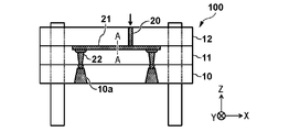
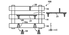
- 1A and 1B are schematic views showing an injection molding apparatus 100 of the present embodiment.
- the injection molding apparatus 100 of the present embodiment is a cold runner type injection molding in which a molten material (molten resin) is injected into a mold 10 (mold hole 10a) via a spru 20, a runner 21 and a second spru 22 (gate). Device.
- a molten material molten resin
- FIG. 1A when the injection molding apparatus 100 injects the molten material into the mold 10, the first plate 11 on which the second sprues 22 are formed and the second plate on which the sprues 20 are formed. 12 and the mold 10 are overlapped.
- the runner 21 is configured when the first plate 11 and the second plate 12 are overlapped. Then, the molten material is injected into the mold 10 through the sprue 20, the runner 21 and the second sprue 22 in a state where the first plate 11, the second plate 12 and the mold 10 are overlapped. After the molten material is cooled and solidified, as shown in FIG. 1B, the runner 21 is divided into two parts by increasing the distance between the first plate 11, the second plate 12 and the mold 10. A part 32 (resin) solidified inside the sprue 20, the runner 21 and the second sprue 22 is taken out together with the formed product 31 formed.
- the cold runner type injection molding apparatus 100 since the parts solidified by the runner 21 are taken out together with the molded product, it takes a certain time until the molten material in the runner 21 is cooled and solidified, and the productivity is increased. Can be reduced. Therefore, in the cold runner type injection molding apparatus 100, it is desired to reduce the cross-sectional area of the runner 21 and shorten the cooling time of the molten material in the runner 21. However, by simply reducing the cross-sectional area of the runner 21, the molten material in the runner 21 is cooled and solidified while the molten material is injected into the mold 10 through the runner 21 (during injection). Short shots can occur.
- the injection molding apparatus 100 of the present embodiment has a configuration in which the runner 21 is surrounded by a metal layer, a heat insulating layer is provided around the metal layer, and a part of the metal layer is connected to the base material. That is, the runner 21 of the present embodiment has a portion surrounded by a metal layer, and in this portion, a heat insulating layer is provided between the metal layer and the base material, and the heat conductivity is higher than the heat insulating layer.
- the metal layer is connected to the base material through a connecting portion that passes through the inside of the heat insulating layer.
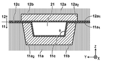
- FIG. 2 is a schematic view showing a cross section (cross section AA in FIG. 1A) of the peripheral portion of the runner 21. As shown in FIG.
- the first plate 11 may include a first base material 11a, a first heat insulating layer 11b, and a first metal layer 11c.
- a first recess 11a 2 having a trapezoidal cross section is formed on the first surface 11a 1 (surface on the second plate 12 side) of the first base material 11a, and the first heat insulation is formed on the inner wall of the first recess 11a 2.
- a layer 11b is provided. As with the first surface 11a at least a portion of one of the first base material 11a covers the surface (exposed surface) of the first heat insulating layer 11b, at least the surface of the first insulation layer 11b of the first surface 11a 1
- the first metal layer 11c is continuously provided up to a part. In other words, the first metal layer 11c is connected to the portion where the metal layer provided on the surface of the first heat insulating layer 11b is not formed with the flow path of the first base material 11a (first surface 11a 1 ). It is formed as follows.
- the first metal layer 11c of the present embodiment includes a portion covering the surface of the first insulation layer 11b, a portion continuously covering at least a portion of the first surface 11a 1 and extends from the partial It is out. That is, in the present embodiment, a part of the first metal layer 11c functions as a connection portion that connects the metal layer surrounding the flow path (runner 21) and the first base material 11a.
- the present invention is not limited to this, and the metal layer provided only in the portion surrounding the flow path 21 is the first metal layer 11c, and as a connection portion that connects the first metal layer 11c and the first base material 11a, A member (for example, metal) having higher thermal conductivity than the first heat insulating layer 11 b may be provided on the first plate 11.
- the second plate 12 may include a second base material 12a, a second heat insulating layer 12b, and a second metal layer 12c.
- a second recess 12a 2 having a rectangular cross section is formed on the second surface 12a 1 (surface on the first plate 11 side) of the second base material 12a, and a second heat insulation is formed on the inner wall of the second recess 12a 2.
- a layer 12b is provided. Then, at least the second surface 12a 1 from the surface of the second heat insulating layer 12b so as to cover at least a part of the second surface 12a 1 of the second base material 12a and the surface (exposed surface) of the second heat insulating layer 12b.
- the second metal layer 12c is continuously provided up to a part.
- the second metal layer 12c is connected to the portion where the metal layer provided on the surface of the second heat insulating layer 12b is not formed with the flow path of the second base material 12a (second surface 12a 1 ). It is formed as follows.
- the second heat insulating layer 12b of the present embodiment can be formed such that the second recess 12a 2 is filled with a heat insulating material.
- the second metal layer 12c of the present embodiment also connects a part of the second metal layer 12c with the metal layer surrounding the flow path 21 and the second base material 12a, similarly to the first metal layer 11c. It functions as a connection part.
- the present invention is not limited to this, and the metal layer provided only in the portion surrounding the flow path (runner 21) is the second metal layer 12c, and the connection connecting the second metal layer 12c and the second base material 12a.
- a member (for example, metal) having higher thermal conductivity than the first heat insulating layer 11b may be provided on the second plate 12.
- it was set as the structure which provided the connection part in both the 1st plate 11 and the 2nd plate 12 it is good also as a structure which provided the connection part in at least one of them.
- first plate 11 and the second plate 12 By configuring the first plate 11 and the second plate 12 in this way, when they are overlapped with each other, a space surrounded by the first metal layer 11c and the second metal layer 12c as shown in FIG. There is formed inside the first recess 11a 2. That is, a space in which the lower surface and the side surface are configured by the first metal layer 11c and the upper surface is configured by the second metal layer 12c is formed inside the first recess. This space becomes a runner 21 (flow path) through which the molten material flows. Furthermore, since the first metal layer 11c and the second metal layer 12c are formed up to the portion where the flow path of the first base material 11a and the second base material 12a is not formed, there is an efficient heat insulation layer. Cooling can be possible.
- the first heat insulating layer 11b and the second heat insulating layer 12b are preferably made of a material having a lower thermal conductivity than the base material (first base material 11a, second base material 12a) such as ceramic or polyimide resin. . More preferably, it may be made of a material (for example, zirconia) having a thermal conductivity of 1 W / mK or less. Moreover, it is preferable that the 1st metal layer 11c and the 2nd metal layer 12c are comprised with a material whose heat conductivity is higher than a heat insulation layer (the 1st heat insulation layer 11b, the 2nd heat insulation layer 12b). For example, the first metal layer 11c and the second metal layer 12c can be made of tungsten.
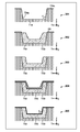
- FIG. 3 is a view for explaining a method of forming the runner portion in the first plate 11.
- a first recess 11a 2 (groove) is formed in the first surface 11a 1 of the first base material 11a (301 in FIG. 3).
- the first recess 11a 2 other portions were masked (covered by the mask 30), by depositing an insulating material by thermal spraying on the inner wall of the first recess 11a 2, the inner wall of the first recess 11a 2 first
- the heat insulation layer 11b is formed (302 in FIG. 3).
- a metal is deposited on the first heat-insulating layer 11b and the first base material 11a by spraying, whereby the surface (exposed surface) of the first heat-insulating layer 11b and the first the first metal layer 11c is formed on the first surface 11a 1 of the base material 11a (304 in FIG. 3).
- the first metal layer 11c formed on the first surface 11a 1 of the first insulation layer 11b and the first base material 11a, the thickness by polishing or the like is adjusted to be the target value (in FIG. 3 305 ). In this way, a runner portion is formed on the first plate 11.
- the first insulation layer 11b and the first metal layer 11c is formed by thermal spraying, it is preferable to have a certain degree of inclination on the side surfaces of the first recess 11a 2. That is, it is preferable to form the first recess 11a 2 so that the cross section has a trapezoidal shape. For example, from the results of experiments and the like, it is preferable to form the first recess 11a 2 so that the angle ⁇ between the lower surface and the side surface of the first recess 11a 2 is in the range of 95 degrees to 105 degrees.
- the runner 21 configured by overlapping the first plate 11 and the second plate 12
- the cross section is trapezoidal, and the angle ⁇ between the lower surface and the side surface of the runner 21 is in the range of 95 degrees to 105 degrees.
- the cross-sectional shape of the first recess 11a 2 is not limited as long as the cured resin can be easily removed from the first plate 11, and may be a trapezoidal shape, a semicircular shape, a shape including a curve, or the like.
- the second plate 12 can be formed through the same process as the first plate 11. First, a second recess 12a 2 (groove) having a rectangular cross section, for example, is formed on the second surface 12a 1 of the second base material 12a. Then, after masking the second recess 12a 2 other portions, by depositing the insulation material by spraying on the inner wall of the second recess 12a 2, the second insulation such that the second recess 12a 2 is filled with a heat insulating material Layer 12b is formed.
- the second heat insulating layer formed in the second recess 12a 2 is polished so that the second surface 12a 1 of the second base material 12a and the exposed surface of the second heat insulating layer 12b are flattened (on the same surface).
- the thickness is adjusted).
- the exposed surface of the first heat insulating layer 12b and the second base material 12a are deposited on the second heat insulating layer 12b and the second base material 12a by thermal spraying.
- the second metal layer 12c is formed on the second surface 12a 2.
- the second metal layer 12c formed on the second surface 12a 1 of the second insulation layer 12b and the second base material 12a, the thickness by polishing or the like is adjusted to be the target value. In this way, a runner portion is formed on the second plate 12.
- the second plate 12 of the present embodiment the second surface 12a 2 of the second base material 12a to form a second recess 12a 2, but in its second recesses 12a 2 provided with second heat-insulating layer 12b It is not limited to that.
- the second plate 12, without forming the second recess 12a 2 was the second insulation layer 12b and a second metal layer 12c are stacked in this order on the second surface 12a 1 of the second base member 12a constituting But you can.
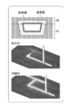
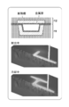
- FIG. 4A and 4B show results of simulating the temperature of the molten material in the runner 21 while the molten material is being injected into the mold 10 (during injection) and while the molten material is being cooled (during cooling).
- FIG. 4A shows a conventional configuration in which the metal layer surrounding the runner 21 is not connected to the base material
- FIG. 4B shows the configuration of this embodiment in which the metal layer surrounding the runner 21 is connected to the base material.
- Yes. 4A and 4B indicate that the temperature increases as it approaches white (lightens) and decreases as it approaches black (darkens).
- FIG. 5 is a diagram showing the apparatus configuration used when simulating the temperature of the molten material in the runner 21, and corresponds to the simulation results shown in FIGS. 4A and 4B.
- the conventional configuration (FIG. 4A) and the configuration of the present embodiment (FIG. 4B) are similar in thickness, material, and the like except that a part of the metal layer surrounding the runner 21 is connected to the base material. It is said.
- the temperature of the molten material in the runner 21 is slightly lower in the configuration of this embodiment (FIG. 4B) than in the conventional configuration (FIG. 4A).
- a sufficient temperature can be maintained for injecting the molten material into the mold 10 without solidifying the runner 21 in the middle.
- the configuration of the present embodiment diffuses the heat of the molten material in the runner 21 to the base material through the metal layer, It can be seen that the temperature of the molten material in the runner 21 is decreasing.
- the length (L) of the runner 21 and the flow direction of the resin of the runner 21 formed between the first plate 11 and the second plate 12 are determined.
- the ratio (aspect ratio (L / De)) of the length (L) of the runner 21 to the equivalent diameter (De) of the orthogonal cross section is preferably 30 to 60, and more preferably 30 to 40.
- the cross-sectional area of the runner 21 can be obtained from the relationship between the cross-sectional area of the runner 21 and the cycle time when the heat insulating layer is not formed.
- the cycle time is the time from the start of the injection of the molten material until the molded product is taken out, and depends on the cooling property of the molten material in the runner 21. For example, when the cooling time of the molten material in the runner 21 is shortened, the cycle time is also shortened.
- the thickness of the heat insulating layer can be obtained from the relationship between the cross-sectional area of the runner 21 and the filling pressure when the thickness of the heat insulating layer is shaken.
- the filling pressure is the pressure of the molten material that fills (injects) the mold 10 through the runner 21 and depends on the heat retaining property of the molten material in the runner 21 during injection. For example, when the temperature of the molten material in the runner 21 during injection decreases, the viscosity of the molten material increases, so the filling pressure increases.
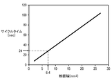
- FIG. 6 is a diagram showing the relationship between the cross-sectional area of the runner 21 and the cycle time when the heat insulation layer is not formed.
- the cooling time of the molten material in the runner 21, that is, the cycle time tends to be linearly shortened.
- the relationship shown in FIG. 6 can be obtained from experiments and simulations, and the cross-sectional area of the runner 21 when the cycle time reaches the target value can be obtained from FIG.
- the target value of the cycle time is set to 24 sec
- the cross-sectional area of the runner 21 can be obtained as 6.2 mm 2 .
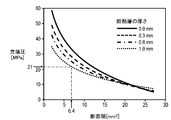
- FIG. 7 is a diagram showing the relationship between the cross-sectional area of the runner 21 and the filling pressure when the thickness of the heat insulating layer is varied.
- FIG. 7 shows the relationship between the cross-sectional area of the runner 21 and the filling pressure when the thickness of the heat insulating layer is 0 mm, 0.3 mm, 0.6 mm, and 1.0 mm.
- the cross-sectional area of the runner 21 is reduced, the cooling performance of the molten material in the runner during injection increases, and the viscosity of the molten material increases accordingly, so the filling pressure increases exponentially. Tend to be. Further, as the thickness of the cross-sectional layer is increased, the filling pressure tends to decrease. The relationship shown in FIG.
- the thickness of the heat insulating material when the filling pressure reaches the target value in the cross-sectional area of the runner 21 obtained from FIG. 6 can be obtained from FIG. .
- the target value of the filling pressure is set to 21 MPa
- the thickness of the heat insulating material when the cross-sectional area of the runner 21 is 6.2 mm 2 can be obtained as 1.0 mm.
- the layer thickness ratio is preferably 0.3 or less, more preferably in the range of 0.001 to 0.3, and still more preferably in the range of 0.005 to 0.2. . That is, when the thickness of the heat insulating layer is 1 mm, the thickness of the metal layer is preferably within the range of 1 ⁇ m to 0.3 mm, and more preferably within the range of 5 ⁇ m to 0.2 mm.
- the injection molding apparatus 100 of the present embodiment has a configuration in which the runner 21 is surrounded by a metal layer, a heat insulating layer is provided around the metal layer, and a part of the metal layer is connected to the base material.
- a heat insulating layer is provided around the metal layer, and a part of the metal layer is connected to the base material.
- the flow path has a portion surrounded by a metal layer, and in this portion, a heat insulating layer is provided between the metal layer and the base material, and the heat conductivity is higher than that of the heat insulating layer and the inside of the heat insulating layer is formed.
- a configuration in which the metal layer is connected to the base material through a connecting portion that passes through may be applied to a flow path other than the runner.
Landscapes
- Engineering & Computer Science (AREA)
- Manufacturing & Machinery (AREA)
- Mechanical Engineering (AREA)
- Moulds For Moulding Plastics Or The Like (AREA)
Abstract
Dans un appareil de moulage par injection qui injecte un matériau fondu dans un moule par l'intermédiaire d'un canal d'écoulement, le canal d'écoulement présente une partie qui est entourée par une couche métallique. Dans ladite partie, une couche d'isolation thermique est située entre la couche métallique et le matériau de base et la couche métallique est reliée au matériau de base par l'intermédiaire d'une section de liaison, qui présente une conductivité thermique supérieure à celle de la couche d'isolation thermique et qui passe à travers la couche d'isolation thermique.
Priority Applications (1)
| Application Number | Priority Date | Filing Date | Title |
|---|---|---|---|
| JP2018509207A JP6805239B2 (ja) | 2016-03-31 | 2017-03-23 | 射出成形装置 |
Applications Claiming Priority (2)
| Application Number | Priority Date | Filing Date | Title |
|---|---|---|---|
| JP2016-071097 | 2016-03-31 | ||
| JP2016071097 | 2016-03-31 |
Publications (1)
| Publication Number | Publication Date |
|---|---|
| WO2017170168A1 true WO2017170168A1 (fr) | 2017-10-05 |
Family
ID=59964443
Family Applications (1)
| Application Number | Title | Priority Date | Filing Date |
|---|---|---|---|
| PCT/JP2017/011828 Ceased WO2017170168A1 (fr) | 2016-03-31 | 2017-03-23 | Appareil de moulage par injection |
Country Status (2)
| Country | Link |
|---|---|
| JP (1) | JP6805239B2 (fr) |
| WO (1) | WO2017170168A1 (fr) |
Citations (3)
| Publication number | Priority date | Publication date | Assignee | Title |
|---|---|---|---|---|
| JPS4929859U (fr) * | 1972-06-14 | 1974-03-14 | ||
| JPS57141025U (fr) * | 1981-02-28 | 1982-09-03 | ||
| JPS6120718A (ja) * | 1984-07-06 | 1986-01-29 | アドヴアンスド セミコンダクタ− マテイリアルズ フイコ ツ−リング ベスロ−テン フエンノ−トチヤツプ | 低温ランナーを有するトランスファー成形装置 |
-
2017
- 2017-03-23 JP JP2018509207A patent/JP6805239B2/ja active Active
- 2017-03-23 WO PCT/JP2017/011828 patent/WO2017170168A1/fr not_active Ceased
Patent Citations (3)
| Publication number | Priority date | Publication date | Assignee | Title |
|---|---|---|---|---|
| JPS4929859U (fr) * | 1972-06-14 | 1974-03-14 | ||
| JPS57141025U (fr) * | 1981-02-28 | 1982-09-03 | ||
| JPS6120718A (ja) * | 1984-07-06 | 1986-01-29 | アドヴアンスド セミコンダクタ− マテイリアルズ フイコ ツ−リング ベスロ−テン フエンノ−トチヤツプ | 低温ランナーを有するトランスファー成形装置 |
Also Published As
| Publication number | Publication date |
|---|---|
| JP6805239B2 (ja) | 2020-12-23 |
| JPWO2017170168A1 (ja) | 2019-02-14 |
Similar Documents
| Publication | Publication Date | Title |
|---|---|---|
| CN106460718B (zh) | 水套用间隔件的制造方法 | |
| JP3843833B2 (ja) | 型内被覆成形用金型 | |
| JP6419518B2 (ja) | インサート成形用金型を用いたインサート成形方法 | |
| JP6142953B1 (ja) | 鋳造方法、および、一対の鋳型 | |
| JP6805239B2 (ja) | 射出成形装置 | |
| CN108621377A (zh) | 注塑模具、电子设备壳体及其加工方法 | |
| JP2015058642A (ja) | 導光板及び金型 | |
| CN105246617B (zh) | 重力铸造装置和重力铸造方法 | |
| JP2006289794A (ja) | 型内被覆成形用金型及び型内被覆成形方法 | |
| JP2013132668A (ja) | シリンダヘッド鋳造用鋳型及びシリンダヘッドの鋳造方法 | |
| KR101248478B1 (ko) | 대면적 사출성형용 단열 스템퍼 코어 | |
| JP2008229963A (ja) | 射出成形用金型 | |
| KR100720367B1 (ko) | 밸브게이트 주변에 에어단열공간을 형성한 핫런너 밸브노즐 | |
| KR200463800Y1 (ko) | 매니폴드용 일체형 시즈히터 | |
| CN108688046A (zh) | 模制产品的制造方法、模制产品和打印机 | |
| JP6103617B1 (ja) | 一対の鋳型およびその製造方法 | |
| JP6265358B1 (ja) | 一対の鋳型、および、その製造方法 | |
| JP2002530221A (ja) | 射出成形方法および射出成形用金型 | |
| JP2003010945A (ja) | 自動車用ホイールの鋳造装置 | |
| JP6143361B2 (ja) | 射出成形用金型 | |
| JP3198763U (ja) | スプルーブッシュ | |
| WO2020208863A1 (fr) | Méthode de production de tube de résine | |
| CN105196504A (zh) | 具有3d冷却水路的复合式模具 | |
| JP3232222B2 (ja) | 金属材料の射出成形用ホットランナ金型 | |
| JP6343974B2 (ja) | 内燃機関のピストン |
Legal Events
| Date | Code | Title | Description |
|---|---|---|---|
| ENP | Entry into the national phase |
Ref document number: 2018509207 Country of ref document: JP Kind code of ref document: A |
|
| NENP | Non-entry into the national phase |
Ref country code: DE |
|
| 121 | Ep: the epo has been informed by wipo that ep was designated in this application |
Ref document number: 17774706 Country of ref document: EP Kind code of ref document: A1 |
|
| 122 | Ep: pct application non-entry in european phase |
Ref document number: 17774706 Country of ref document: EP Kind code of ref document: A1 |