WO2017170224A1 - Dispositif d'affichage pourvu d'un panneau tactile - Google Patents
Dispositif d'affichage pourvu d'un panneau tactile Download PDFInfo
- Publication number
- WO2017170224A1 WO2017170224A1 PCT/JP2017/012011 JP2017012011W WO2017170224A1 WO 2017170224 A1 WO2017170224 A1 WO 2017170224A1 JP 2017012011 W JP2017012011 W JP 2017012011W WO 2017170224 A1 WO2017170224 A1 WO 2017170224A1
- Authority
- WO
- WIPO (PCT)
- Prior art keywords
- touch panel
- electrode
- display device
- housing
- capacitance
- Prior art date
- Legal status (The legal status is an assumption and is not a legal conclusion. Google has not performed a legal analysis and makes no representation as to the accuracy of the status listed.)
- Ceased
Links
Images












Classifications
-
- G—PHYSICS
- G06—COMPUTING OR CALCULATING; COUNTING
- G06F—ELECTRIC DIGITAL DATA PROCESSING
- G06F3/00—Input arrangements for transferring data to be processed into a form capable of being handled by the computer; Output arrangements for transferring data from processing unit to output unit, e.g. interface arrangements
- G06F3/01—Input arrangements or combined input and output arrangements for interaction between user and computer
- G06F3/03—Arrangements for converting the position or the displacement of a member into a coded form
- G06F3/041—Digitisers, e.g. for touch screens or touch pads, characterised by the transducing means
- G06F3/044—Digitisers, e.g. for touch screens or touch pads, characterised by the transducing means by capacitive means
- G06F3/0446—Digitisers, e.g. for touch screens or touch pads, characterised by the transducing means by capacitive means using a grid-like structure of electrodes in at least two directions, e.g. using row and column electrodes
-
- G—PHYSICS
- G02—OPTICS
- G02F—OPTICAL DEVICES OR ARRANGEMENTS FOR THE CONTROL OF LIGHT BY MODIFICATION OF THE OPTICAL PROPERTIES OF THE MEDIA OF THE ELEMENTS INVOLVED THEREIN; NON-LINEAR OPTICS; FREQUENCY-CHANGING OF LIGHT; OPTICAL LOGIC ELEMENTS; OPTICAL ANALOGUE/DIGITAL CONVERTERS
- G02F1/00—Devices or arrangements for the control of the intensity, colour, phase, polarisation or direction of light arriving from an independent light source, e.g. switching, gating or modulating; Non-linear optics
- G02F1/01—Devices or arrangements for the control of the intensity, colour, phase, polarisation or direction of light arriving from an independent light source, e.g. switching, gating or modulating; Non-linear optics for the control of the intensity, phase, polarisation or colour
- G02F1/13—Devices or arrangements for the control of the intensity, colour, phase, polarisation or direction of light arriving from an independent light source, e.g. switching, gating or modulating; Non-linear optics for the control of the intensity, phase, polarisation or colour based on liquid crystals, e.g. single liquid crystal display cells
- G02F1/133—Constructional arrangements; Operation of liquid crystal cells; Circuit arrangements
- G02F1/1333—Constructional arrangements; Manufacturing methods
- G02F1/13338—Input devices, e.g. touch panels
-
- G—PHYSICS
- G06—COMPUTING OR CALCULATING; COUNTING
- G06F—ELECTRIC DIGITAL DATA PROCESSING
- G06F3/00—Input arrangements for transferring data to be processed into a form capable of being handled by the computer; Output arrangements for transferring data from processing unit to output unit, e.g. interface arrangements
- G06F3/01—Input arrangements or combined input and output arrangements for interaction between user and computer
- G06F3/03—Arrangements for converting the position or the displacement of a member into a coded form
- G06F3/041—Digitisers, e.g. for touch screens or touch pads, characterised by the transducing means
- G06F3/0412—Digitisers structurally integrated in a display
-
- G—PHYSICS
- G06—COMPUTING OR CALCULATING; COUNTING
- G06F—ELECTRIC DIGITAL DATA PROCESSING
- G06F3/00—Input arrangements for transferring data to be processed into a form capable of being handled by the computer; Output arrangements for transferring data from processing unit to output unit, e.g. interface arrangements
- G06F3/01—Input arrangements or combined input and output arrangements for interaction between user and computer
- G06F3/03—Arrangements for converting the position or the displacement of a member into a coded form
- G06F3/041—Digitisers, e.g. for touch screens or touch pads, characterised by the transducing means
- G06F3/0416—Control or interface arrangements specially adapted for digitisers
- G06F3/0418—Control or interface arrangements specially adapted for digitisers for error correction or compensation, e.g. based on parallax, calibration or alignment
- G06F3/04186—Touch location disambiguation
-
- G—PHYSICS
- G06—COMPUTING OR CALCULATING; COUNTING
- G06F—ELECTRIC DIGITAL DATA PROCESSING
- G06F2203/00—Indexing scheme relating to G06F3/00 - G06F3/048
- G06F2203/041—Indexing scheme relating to G06F3/041 - G06F3/045
- G06F2203/04107—Shielding in digitiser, i.e. guard or shielding arrangements, mostly for capacitive touchscreens, e.g. driven shields, driven grounds
Definitions
- the present invention relates to a display device with a touch panel.
- a transmission electrode driven by a driving voltage
- a first reception electrode for reading a first signal based on a first capacitance between the transmission electrode
- a first reception electrode for reading a first signal based on a first capacitance between the transmission electrode
- a capacitive touch panel that is disposed at a position farther away from the transmission electrode and has a second reception electrode for reading a second signal based on the second capacitance between the transmission electrode and the transmission electrode.
- the capacitance-type touch panel described in Patent Document 1 includes a change in capacitance between the transmission electrode and the first reception electrode when the detection target approaches the touch panel, and the transmission electrode and the second reception electrode. Whether the detection object is a conductive material or a non-conductive material is determined on the basis of the change in capacitance between the two.
- the conventional technology as described above has a problem that a touch cannot be detected correctly when the touch panel is wet with water.
- reception electrodes R are schematic cross-sectional views for explaining a problem when water droplets are present on the touch panel.
- the first and second reception electrodes are collectively described as reception electrodes R.
- the capacitive touch panel 4 includes a plurality of transmission electrodes T and a plurality of reception electrodes R formed on the liquid crystal panel 2. As shown in FIG. 34A, the mutual capacitance between the transmission electrode T and the reception electrode R decreases in the area touched by the finger as the detection target. And in the area
- the present invention has been made in view of the above problems, and an object thereof is to realize a display device with a touch panel that can accurately detect a touch position on a touch panel where water droplets are present.
- a display device with a touch panel includes a display panel, a touch panel for operating the display panel, and a controller with a touch panel that controls the touch panel.
- An apparatus, wherein the touch panel includes a transmission electrode driven by a driving voltage, a first reception electrode for reading a first signal based on a first capacitance between the transmission electrode, and the first reception.
- a second receiving electrode that is arranged at a position farther from the transmitting electrode than the electrode and reads a second signal based on a second capacitance between the transmitting electrode and the controller; When a water droplet is present on the touch panel, the frequency for reading the second signal is increased.
- FIG. 1 is a plan view of a display device with a touch panel according to Embodiment 1.
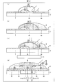
- FIG. (A) (b) (c) (d) is sectional drawing explaining the concept which detects the finger
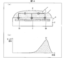
- (A) is sectional drawing explaining the concept which detects the finger wet with the water droplet by a lower reading frequency
- (b) is a graph which shows the relationship between the touch signal at that time and a detection position.
- A) is sectional drawing explaining the concept which detects the finger wet with the water droplet with a higher reading frequency
- (b) is a graph which shows the relationship between the touch signal at that time and a detection position.
- a touch signal in a state with a touch is shown, (c) shows a signal in a state without a touch in a water drop environment, and (d) shows a touch signal in a state with a touch in a water drop environment. It is a graph for demonstrating the touch signal in 5 MHz of the wet finger by the said display apparatus with a touchscreen, (a) shows the signal in the state without a touch in a dry environment, (b) is in a dry environment.
- a touch signal in a state with a touch is shown, (c) shows a signal in a state without a touch in a water drop environment, and (d) shows a touch signal in a state with a touch in a water drop environment.
- FIG. 6 is a flowchart illustrating an operation of the display device with a touch panel according to the second embodiment.
- 10 is a flowchart illustrating another operation of the display device with a touch panel according to the second embodiment.
- A is a top view which shows the pattern of the transmission electrode, 1st receiving electrode, and 2nd receiving electrode which were provided in the other display apparatus with a touchscreen which concerns on Embodiment 2
- (b) is the said transmitting electrode
- It is a top view which shows the other pattern of a 1st receiving electrode and a 2nd receiving electrode.
- It is a perspective view of the display apparatus with a touchscreen which concerns on Embodiment 3.
- FIG. 1 It is sectional drawing which shows the structure of the liquid crystal panel provided in the said display apparatus with a touch panel, a capacitive touch panel, and a housing. It is a block diagram of the said display apparatus with a touch panel. It is a schematic plan view of the display device with a touch panel. It is an exploded view for demonstrating the structure of the capacitive touch panel and housing of the said display apparatus with a touch panel. It is typical sectional drawing of the said display apparatus with a touch panel. It is a schematic cross section which shows the connection structure of the transmission electrode provided in the said capacitive touch panel, a receiving electrode, and a housing.
- FIG. 10 is a perspective view of still another display device with a touch panel according to Embodiment 4.
- 10 is a plan view of a display device with a touch panel according to Embodiment 5.
- (A) (b) is a schematic cross section which shows the connection structure of the wiring provided in the touchscreen of the display apparatus with a touchscreen which concerns on Embodiment 6, and the housing transmission electrode formed in the housing.
- (A) is a typical top view of a display with a touch panel concerning Embodiment 7, and (b) is the typical sectional view.
- (A) is a typical top view of the conventional display apparatus with a touch panel, (b) is the typical sectional drawing.
- (A) is a schematic top view of the other display apparatus with a touchscreen which concerns on Embodiment 7,
- (b) is the typical sectional drawing.
- (A) is a schematic plan view of still another display device with a touch panel according to Embodiment 7, and (b) is a schematic sectional view thereof.
- (A) is a typical top view of the conventional display apparatus with a touch panel, (b) is the typical sectional drawing.
- (A) is a perspective view of the display apparatus with a touchscreen which concerns on Embodiment 8,
- (b) is a circuit diagram of the proximity sensor provided in the said display apparatus with a touchscreen.
- (A) is a perspective view of the other display apparatus with a touchscreen which concerns on Embodiment 8,
- (b) is typical sectional drawing of the said display apparatus with a touchscreen
- (c) is provided in the said display apparatus with a touchscreen.
- It is a circuit diagram of an environmental sensor.
- (A) is a perspective view of the other display apparatus with a touchscreen which concerns on Embodiment 8,
- (b) is typical sectional drawing of the said display apparatus with a touchscreen.
- (A) is a perspective view of the other display apparatus with a touchscreen which concerns on Embodiment 8,
- (b) is typical sectional drawing of the said display apparatus with a touchscreen,
- (c) is provided in the said display apparatus with a touchscreen. It is a block diagram which shows the relationship between the loop antenna, near field communication radar, and a sense circuit.
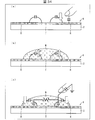
- (A) (b) (c) is typical sectional drawing for demonstrating the subject when a water droplet exists on a touch panel.
- FIG. 1 is a plan view of a display device 1 with a touch panel according to the first embodiment.
- a display device with a touch panel 1 includes a liquid crystal panel 2 (display panel), a capacitive touch panel 4 (with a touch panel) provided on the liquid crystal panel 2 for operating the liquid crystal panel 2, and a capacitive touch panel. 4 is provided with a touch panel controller 10 (controller) for controlling 4.
- a touch panel controller 10 controller
- the capacitive touch panel 4 includes a plurality of transmission electrodes T, a plurality of first reception electrodes SA, and a plurality of second reception electrodes SB.
- the transmission electrodes T are formed in parallel to each other along the X direction and are driven by a driving voltage from the touch panel controller 10.
- the first receiving electrode SA reads the first signal based on the first capacitance between the transmitting electrode T and the base pattern 21A formed along the Y-axis direction.
- a plurality of comb-teeth patterns 22A projecting in the direction.
- the second receiving electrode SB reads the second signal based on the second capacitance between the transmitting electrode T and the base pattern 21B formed along the Y-axis direction, and the X-axis negative from the base pattern 21B.
- a plurality of comb-teeth patterns 22B projecting so as to mesh with the comb-teeth pattern 22A in the direction.
- the comb-tooth pattern 22B of the second reception electrode SB is arranged at a position farther from the transmission electrode T than the comb-tooth pattern 22A of the first reception electrode SA.
- 2A, 2B, 2C, and 2D are cross-sectional views for explaining the concept of detecting a finger wet with a water droplet W by the display device 1 with a touch panel.
- an area on the touch panel wet with water is detected, and a signal from the first reception electrode SA that is relatively close to the transmission electrode T in the wet area is transmitted.
- a signal from the second receiving electrode SB relatively far from the electrode T is transmitted.
- the touch signal when touching the wet touch panel is controlled, and the touch position is accurately detected.
- both the touch signal from the first reception electrode SA and the touch signal from the second reception electrode SB have the same frequency or the same sense signal. Read by parameter.
- the second receiving electrode SB is used for reading the touch signal
- the first receiving electrode SA is used to control the touch signal on the second receiving electrode SB or as a reference value. Can be used.
- FIG. 3A is a cross-sectional view illustrating the concept of detecting a finger wet with a water droplet at a lower readout frequency
- FIG. 3B is a graph showing the relationship between the touch signal and the detection position at that time.
- FIG. 4A is a cross-sectional view for explaining the concept of detecting a finger wet with a water droplet at a higher readout frequency
- FIG. 4B is a graph showing the relationship between the touch signal and the detection position at that time. .
- the readout frequency when the touch signal is read out from the second reception electrode SB is lower, the water behaves like a conductor, so that the touch detection position of the finger spreads over the area wetted with water.
- the peak position L1 of the touch signal on the second receiving electrode SB arranged at the position corresponding to the finger touching the touch panel but also the touched finger is supported.
- the peak position L2 is detected even on the first receiving electrode SA that is disposed at a position that is not wetted with the water droplet W. For this reason, the touch detection position becomes unclear, a ghost touch is observed, and the touch panel tends to malfunction.
- Water resistance is relatively high, and the capacitance between the transmission electrode T and the second reception electrode SB and the resistance of the water droplet W operate as a band-pass filter. High frequency signals pass through the capacitance, and low frequency signals pass through the resistor. Since the water droplet W also has an insulating property or has a higher dielectric constant ( ⁇ r: 80), a sufficient capacitance can be obtained from the transmission electrode T to the second reception electrode SB. If there is sufficient capacitance, the touch signal can be read at a high frequency.
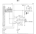
- FIG. 5 is a circuit diagram showing the relationship between the capacitive touch panel 4 and the touch panel controller 10 provided in the display device 1 with a touch panel.
- the touch panel controller 10 has a sense amplifier A1.
- the second receiving electrode SB is connected to the plus side input terminal of the sense amplifier A1, and the reference voltage Vref is inputted to the minus side input terminal.
- An integration capacitor C1 and a switch SW are provided in parallel between the positive side input terminal and the output of the sense amplifier A1.
- the touch panel controller 10 has resistors R1 and R2 connected in series. The opposite side of the resistor R1 from the resistor R2 is connected to the power supply voltage VDD.
- the resistance R2 is related to a reference value related to the water droplet W on the touch panel.
- the touch panel controller 10 is provided with comparators A2, A3, and A4.
- the second receiving electrode SB is connected to the plus side input terminal of the comparator A2, and the minus side input terminal is connected between the resistor R1 and the resistor R2.
- the second receiving electrode SB is connected to the negative input terminal of the comparator A3, and the positive input terminal is connected between the resistors R1 and R2.
- the second receiving electrode SB is connected to the plus side input terminal of the comparator A4, and the minus side input terminal is connected to the output of the comparator A4.
- the touch panel controller 10 includes transistors Tr1 and Tr2 and power supplies B1 and B2.
- the source electrode of the transistor Tr1 is connected to the first receiving electrode SA, the drain electrode is connected to the power source B2, and the gate electrode is connected to the output of the comparator A2.
- the source electrode of the transistor Tr2 is connected to the first receiving electrode SA, the drain electrode is connected to the output of the comparator A4, and the gate electrode is connected to the output of the comparator A3.
- the power supply B1 is connected to the transmission electrode T.
- the AC frequency f2 of the power source B2 is higher than the AC frequency f1 of the power source B1.
- the water droplet W on the surface of the capacitive touch panel 4 is detected by a signal from the second reception electrode SB that is farther from the transmission electrode T than the first reception electrode SA. Since the dielectric constant of water is high, if a water droplet W is present on the touch panel, the mutual capacitance between the transmission electrode T and the second reception electrode SB becomes very high, and the voltage value of the signal read from the second reception electrode SB becomes high. Get higher. There is a possibility that the voltage value of this signal exceeds the value corresponding to the integral capacity of the touch panel controller than in normal (no water drop state).
- the transistor Tr1 When the voltage value of the signal read from the second receiving electrode SB exceeds the reference value Vref for the water drop corresponding to the resistor R2, the transistor Tr1 is turned on by the output of the comparator A2, and the current in the sense amplifier A1 is limited.
- a power source B2 having an AC frequency f2 higher than the AC frequency f1 of the power source B1 is connected to the first receiving electrode SA. Then, the value of the reference parameter is changed.
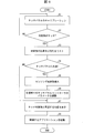
- FIG. 6 is a flowchart showing the operation of the display device 1 with a touch panel.
- the calibration of the touch panel controller 10 is executed by resetting the amplifier and the like at least with respect to reading of the signal from the second receiving electrode SB (step S1). Specifically, the touch panel controller 10 compares the capacitance of all nodes with a predetermined reference capacitance, and executes calibration using a preset value in order to remove noise.
- the reference voltage Vref2 for the wet touch panel where the water droplet W exists is set higher than the reference voltage Vref1 for the dry environment of the touch panel.
- the touch panel controller 10 determines whether the detection target object touched the electrostatic capacitance type touch panel 4 (step S2). When it is not determined that the detection target object has touched the capacitive touch panel 4 (NO in step S2), the process returns to step S1.
- the touch panel controller 10 When it is determined that the detection target touches the capacitive touch panel 4 (YES in step S2), the touch panel controller 10 creates a list of the touch positions and characteristics of the detection target (step S3). Next, the touch panel controller 10 determines whether or not there is a water droplet W on the capacitive touch panel 4 (step S4).
- the power supply B1 shown in FIG. 5 drives the transmission electrode T with a signal Vin1 having a low frequency. Then, the low frequency signal Vin1 from the transmission electrode T is coupled to the first reception electrode SA and the second reception electrode SB. Then, the transistor Tr2 is turned on by the output of the comparator A3, the first reception electrode SA is connected to the second reception electrode SB via the comparator A4, and the first reception electrode SA is kept at the same voltage as the second reception electrode SB. Active guard.
- the touch panel controller 10 reads at least a signal from the second reception electrode SB in the area where the water drop exists. Is increased (step S5).
- the frequency for reading a signal can be increased by shortening the sampling time for reading the signal or changing the integration time for reading the signal.
- the signal voltage read from the second receiving electrode SB becomes higher than the reference voltage Vref2 for water droplets.
- the comparator A2 connects the first reception electrode SA to the power source B2 that supplies the signal Vin2 having a frequency higher than that of the signal Vin1.
- the parameters in each area are adjusted by the touch panel controller 10 (step S6).
- Parameters of the touch panel controller 10 such as capacitance gain, sampling time, and integration time are adjusted to parameters for the water droplet environment.
- step S6 When the touch panel controller 10 does not determine that water droplets are present on the capacitive touch panel 4 (NO in step S4), or when the reference value in each area is adjusted by the touch panel controller 10 (step S6).
- the detection object and the touch position are displayed (step S7). Thereafter, the touch panel controller 10 activates a related application (step S8).
- FIG. 7 is a graph showing the detection result of the touch signal by the display device 1 with a touch panel, where (a) shows the detection result by the low frequency, and (b) shows the detection result by the high frequency.
- FIG. 8 is a graph for explaining a touch signal at 100 kHz of a finger wet with water by the display device with a touch panel 1, and (a) shows a signal P ⁇ b> 1 in a dry environment with no touch. b) shows a signal P2 in a dry environment with a touch, (c) shows a signal P3 in a water drop environment without a touch, and (d) shows a signal in a water drop environment with a touch. P4 is shown.
- the signal rise time changes from the dry environment shown in FIGS. 8A and 8B in the water drop environment shown in FIGS.
- FIG. 9 is a graph for explaining a touch signal at 5 MHz of a finger wet with water by the display device 1 with a touch panel.
- FIG. 9A shows a signal P5 in a dry environment with no touch.
- b) shows a signal P6 in a dry environment with touch
- c) shows a signal P7 in a water drop environment without touch
- d) shows a signal in a water drop environment with touch.
- P8 is shown.
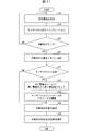
- FIG. 10 is a flowchart showing the operation of the display device with a touch panel according to the second embodiment.
- the first reception electrode SA is set to an electrode close to the transmission electrode T
- the second reception electrode SB is set to an electrode farther from the transmission electrode T than the first reception electrode SA (step S9).
- calibration (calibration) of the touch panel controller 10 is executed (step S10).
- the touch panel controller 10 determines whether or not there is a water droplet W on the capacitive touch panel 4 (step S11).
- the touch panel controller 10 stores the position of the water droplet W in the memory (step S12). Then, the touch panel controller 10 changes the sampling time and the integration time for reading signals from the first reception electrode SA and the second reception electrode SB (step S13). The sampling time is shortened so that the touch panel controller 10 can sufficiently detect a signal from the first reception electrode SA closer to the transmission electrode T than the second reception electrode SB.
- step S14 the water droplet environment mode is activated.
- the capacitance touch panel 4 has a detection target.
- the touch panel controller 10 determines whether or not a touch has been made (step S15).
- step S15 If the touch panel controller 10 does not determine that the detection target has touched the capacitive touch panel 4 (NO in step S15), the process returns to step S9.
- the touch panel controller 10 determines that the detection target object has touched the capacitive touch panel 4 (YES in step S15)
- the touch panel controller 10 detects the position of the detection target touched on the capacitive touch panel 4. (Step S16). Thereafter, the characteristics of the detection object and the touch position are displayed (step S17).
- FIG. 11 is a flowchart showing another operation of the display device with a touch panel according to the second embodiment.
- the first reception electrode SA is set to an electrode close to the transmission electrode T
- the second reception electrode SB is set to an electrode farther from the transmission electrode T than the first reception electrode SA (step S18).
- calibration (calibration) of the touch panel controller 10 is executed (step S19).
- the touch panel controller 10 determines whether or not the detection target object has touched the capacitive touch panel 4 (step S20). When the touch panel controller 10 does not determine that the detection target object has touched the capacitive touch panel 4 (NO in step S20), the process returns to step S18.
- Step S20 the position of the detection target touched on the capacitive touch panel 4 is stored in the memory (Step S20). S21).
- the touch panel controller 10 determines whether or not there is a water droplet W on the capacitive touch panel 4 (step S22).
- the first receiving electrode SA closer to the transmitting electrode T than the second receiving electrode SB is shielded, and the first receiving electrode SA
- the touch panel controller 10 reads a signal from the second reception electrode SB farther from the transmission electrode T at a higher frequency (step S23).
- the shielding of the first receiving electrode SA can be performed by turning off a switch provided between the first receiving electrode SA and the touch panel controller 10.
- the frequency for reading the signal from the second reception electrode SB can be increased by shortening the sampling time for reading the signal from the second reception electrode SB, for example.
- step S24 the parameters of the touch panel controller 10 are adjusted (step S24).
- the capacitive touch panel 4 is The touch panel controller 10 detects the position of the touched detection target (step S25). Thereafter, the characteristics of the detection target and the touch position are displayed (step S26).
- FIG. 12A is a plan view illustrating patterns of the transmission electrode T, the first reception electrode SA, and the second reception electrode SB provided in still another display device with a touch panel according to the second embodiment
- FIG. FIG. 6 is a plan view showing another pattern of the transmission electrode T, the first reception electrode SA, and the second reception electrode SB.
- each of the plurality of transmission electrodes T arranged in parallel with each other along the X-axis direction is formed by repeating a hexagonal pattern.
- Each of the plurality of first reception electrodes SA arranged along the Y-axis direction is formed along the hexagonal outer edge of each transmission electrode T.
- Each of the plurality of second reception electrodes SB arranged along the Y-axis direction is formed by repeating a substantially rhombic pattern at a position farther from the transmission electrode T than the first reception electrode SA.
- a wiring Tw connected to the transmission electrode T, a wiring SAw connected to the first reception electrode SA, and a wiring SBw connected to the second reception electrode SB are formed on the liquid crystal panel 2.
- a plurality of strip-shaped transmission electrodes T are arranged in parallel to each other along the Y-axis direction.
- the first receiving electrode SA having a substantially U shape is disposed between the transmitting electrodes T adjacent to each other.
- a plurality of strip-shaped second reception electrodes SB are formed inside the U-shape of each transmission electrode T.
- the second reception electrode SB is arranged at a position farther from the transmission electrode T than the first reception electrode SA.
- both the first receiving electrode SA and the second receiving electrode SB arranged at a position farther from the transmitting electrode T than the first receiving electrode SA are on the surface of the liquid crystal panel 2.
- the second receiving electrode SB may be disposed in a housing that houses the liquid crystal panel 2.
- the housing transmission electrode HT and the like may be configured as a housing reception electrode.
- the second reception electrode SB described in the first and second embodiments can be applied to the case reception electrode or the like.
- the first receiving electrode SA described in the first and second embodiments can be applied to the receiving electrode R in the third to eighth embodiments.
- the touch position on the housing can be accurately detected even when water droplets are present in the housing that accommodates the liquid crystal panel 2.
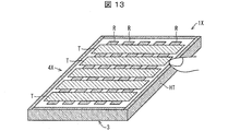
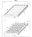
- FIG. 13 is a perspective view of a display device with a touch panel 1X according to the third embodiment.
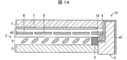
- FIG. 14 is a cross-sectional view illustrating the configuration of the liquid crystal panel 2 (display panel), the capacitive touch panel 4X, and the housing 3 provided in the display device with a touch panel 1X.
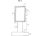
- FIG. 15 is a block diagram of the display device 1X with a touch panel.
- the display device 1X with a touch panel controls the liquid crystal panel 2, a rectangular parallelepiped casing 3 that accommodates the liquid crystal panel 2, a capacitive touch panel 4X for operating the liquid crystal panel 2, and a capacitive touch panel 4X.
- the liquid crystal panel 2 includes a TFT substrate 5, a cover glass 7, and a liquid crystal layer 6 formed between the TFT substrate 5 and the cover glass 7.
- a capacitive touch panel 4X is disposed between the liquid crystal layer 6 and the cover glass 7.
- a seal member 8 is provided between the capacitive touch panel 4X and the TFT substrate 5.
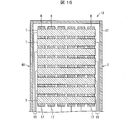
- FIG. 16 is a schematic plan view of the display device with a touch panel 1X.
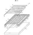
- FIG. 17 is an exploded view for explaining the configuration of the capacitive touch panel 4X and the housing 3 of the display device with a touch panel 1X.
- FIG. 18 is a schematic cross-sectional view of the display device with a touch panel 1X.
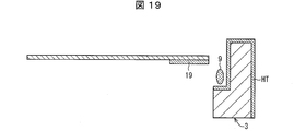
- FIG. 19 is a schematic cross-sectional view showing a connection configuration of the transmission electrode T, the reception electrode R, and the housing 3 provided on the capacitive touch panel 4X.
- the capacitive touch panel 4X is arranged in parallel with each other and is driven in parallel with each other so as to intersect with the plurality of transmission electrodes T and is driven with the driving voltage.
- a plurality of strip-shaped receiving electrodes R for reading out signals based on the capacitance between the transmitting electrodes T and the transmitting electrodes T are provided on the liquid crystal panel 2.
- the transmission electrode T is connected to the touch panel controller 10X via the wiring 17, and the reception electrode R is connected to the touch panel controller 10X via the wiring 18.
- the capacitive touch panel 4X further includes a housing transmission electrode HT that is continuously formed along the four side walls of the housing 3 and driven by a driving voltage.
- the housing transmission electrode HT is formed from the outer surface of the side wall of the housing 3 to the inner surface through the surface, and is connected to the touch panel controller 10 ⁇ / b> X via the conductive seal member 9 provided on the inner surface of the side wall of the housing 3 and the wiring 19.
- the housing transmission electrode HT is continuously formed along the side wall of the housing 3, the electrode formation is easy. For example, if the housing 3 is made of metal, there is no need to additionally form an electrode for the housing transmission electrode HT.
- the touch panel controller 10 ⁇ / b> X reads a signal based on a change in capacitance between the housing transmission electrode HT and the reception electrode R through the reception electrode R and the wiring 17, thereby detecting a finger touch on the housing 3 satisfactorily. can do.
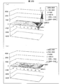
- FIG. 20A is a graph showing a touch signal distribution detected when touching the housing 3 of the display device with a touch panel 1X
- FIG. 20B is a touch detected when touching the housing of the conventional display device with a touch panel. It is a graph which shows signal distribution.
- FIG. 21A is a perspective view of a display device with a touch panel 1A according to the second embodiment
- FIG. 21B is a perspective view of another display device with a touch panel 1B according to the second embodiment.
- the capacitive touch panel 4A of the display device with a touch panel 1A is continuously formed in a U shape along the three side walls of the housing 3, and is driven by a driving voltage.
- a housing transmission electrode HAT is provided.
- the capacitive touch panel 4B of the display device 1B with a touch panel is continuously formed in an I shape along one side wall of the housing 3 and driven by a driving voltage.
- a housing transmission electrode HBT is provided.
- the housing transmission electrodes HAT and HBT are continuously formed along the side wall of the housing 3, the electrodes can be easily formed. For example, if the housing 3 is made of metal, there is no need to additionally form electrodes for the housing transmission electrodes HAT / HBT.
- FIG. 22 is a perspective view of still another display device 1C with a touch panel according to the second embodiment.
- the capacitive touch panel 4 ⁇ / b> C of the display device with a touch panel 1 ⁇ / b> C includes a plurality of housing transmission electrodes HCT formed by being divided along the side wall of the housing 3.
- the plurality of housing transmission electrodes HCT are formed on the outer surface of the side wall of the housing 3.
- the transmission electrode T and the reception electrode R shown in the embodiment have a band-like pattern.
- the present invention is not limited to this.
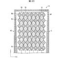
- FIG. 23 is a plan view of a display device with a touch panel 1D according to the fifth embodiment.
- symbol is attached and the description is abbreviate
- the capacitive touch panel 4D of the display device with a touch panel 1D is arranged in parallel to each other so as to intersect with the plurality of transmission electrodes TD that are arranged in parallel to each other and driven by a driving voltage, And a plurality of receiving electrodes RD for reading out signals based on capacitance between the transmitting electrodes TD driven by the driving voltage.
- Each transmission electrode TD has a shape formed by repeating a substantially rhombus shape in the X-axis direction.
- Each receiving electrode RD has a shape formed by repeating a substantially octagonal shape in the Y-axis direction.
- the casing transmission electrode HT of the casing 3 shown in the embodiment is connected to the wiring 19 coupled to the touch panel controller 10 via the conductive seal member 9.
- the present invention is not limited to this.
- FIGS. 24A and 24B are schematic cross-sectional views showing a connection configuration between the wiring 19 provided on the touch panel of the display device with a touch panel according to the sixth embodiment and the housing transmission electrode HT formed on the housing 3.
- symbol is attached and the description is abbreviate
- the housing transmission electrode HT may be connected to the wiring 19 through the flexible connector 11 as shown in FIG.
- housing transmission electrode HT may be connected to the wiring 19 through the cover glass 7 as shown in FIG.
- the casing 3 shown in the embodiment has a rectangular parallelepiped shape.
- the present invention is not limited to this.
- FIG. 25 (a) is a schematic plan view of a display device with a touch panel 1E according to Embodiment 5, and FIG. 25 (b) is a schematic cross-sectional view thereof.
- FIG. 26A is a schematic plan view of a conventional display device 91E with a touch panel, and FIG. 26B is a schematic cross-sectional view thereof.
- symbol is attached and the description is abbreviate
- the conventional disk-shaped display device 91E with a touch panel has no electrode on the housing 3E, and even if the housing 3E is touched, the detection signal becomes low and the touch detection is performed. It was difficult.
- the housing 3E of the display device with a touch panel 1E has a disc shape and accommodates a disc-shaped display panel (not shown).
- a circular capacitive touch panel 4E is disposed on a disk-shaped display panel.
- the capacitive touch panel 4E is provided with a casing transmission electrode HET formed on the outer edge and peripheral surface of the surface of the casing 3E.
- the capacitive touch panel 4E is arranged in parallel with each other and is driven in parallel with each other so as to intersect with the plurality of transmission electrodes T and is driven by the driving voltage.
- a plurality of strip-shaped receiving electrodes R for reading out signals based on the capacitance between the transmitting electrodes T and the transmitting electrodes T are provided on the display panel.
- FIG. 27A is a schematic plan view of another display device with a touch panel 1F according to the fifth embodiment, and FIG. 27B is a schematic cross-sectional view thereof.
- the capacitive touch panel 4F of the display device with a touch panel 1F includes a housing transmission electrode HFT formed on a disk-shaped housing 3E and a plurality of square receiving electrodes R arranged in a matrix on the display panel. Have.
- the touch position on the housing 3E can be detected with high sensitivity by forming the housing transmitting electrode HFT on the housing 3E. .
- the housing 3E when the housing 3E is configured in a disc shape, for example, when the display devices with a touch panel 1E and 1F are mounted on an automobile as a volume indicator of an acoustic device, the side surface of the housing 3E is touched. Therefore, it is possible to adjust the volume by moving the finger while making the finger contact the side surface of the housing 3E (hereinafter also referred to as “tracing”). It is considered that the feeling of operation is improved by tracing the side surface of the housing 3E rather than tracing the surface of the touch panel. Moreover, it is considered that the side surface of the housing 3E is easier to trace than the surface of the touch panel, and the operability and safety when operating while driving are improved.
- FIG. 28A is a schematic plan view of still another display device 1G with a touch panel according to the fifth embodiment, and FIG. 28B is a schematic cross-sectional view thereof.
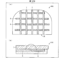
- FIG. 29A is a schematic plan view of a conventional display device 91G with a touch panel, and FIG. 29B is a schematic cross-sectional view thereof.
- the conventional display device 91G with an odd-shaped touch panel has no electrode on the housing 3G, and even if the housing 3G is touched, the detection signal becomes low, and the touch detection is performed. It was difficult.
- the housing 3G of the display device with a touch panel 1G has an irregular shape having a horizontally long rectangular shape in which the upper left corner and the upper right corner are processed in a curved shape when viewed from the front. And accommodates the irregularly shaped display panel (not shown).
- An irregular-shaped capacitive touch panel 4G is disposed on the irregular-shaped display panel.
- the capacitive touch panel 4G is provided with a casing transmission electrode HGT formed on the outer edge and the peripheral surface of the surface of the casing 3G.
- FIG. 30A is a perspective view of a display device with a touch panel 1H according to the sixth embodiment
- FIG. 30B is a circuit diagram of a proximity sensor provided in the display device with a touch panel 1H.
- symbol is attached and the description is abbreviate
- the touch panel-equipped display device 1H includes a capacitive touch panel 4H and a touch panel controller 10H that controls the capacitive touch panel 4H.
- the capacitive touch panel 4H includes a housing transmission electrode HT that is continuously formed along the four side walls of the housing 3 and is driven by a driving voltage.
- the housing transmission electrode HT has a loop shape, and can be configured to have a larger area than the transmission electrode T and the reception electrode R arranged on the surface of the display panel. Therefore, as shown in FIG. 30B, the touch panel controller 10H is provided with an amplifier 12H that receives a signal from the receiving electrode R corresponding to the housing transmitting electrode HT and a reference voltage corresponding to the housing transmitting electrode HT. Thus, the display device with a touch panel 1H can realize the proximity sensor function.
- the touch panel controller 10H can detect an object approaching the housing transmission electrode HT and can identify characteristics of the object approaching the housing transmission electrode HT. For example, the touch panel controller 10H can identify whether the object approaching the housing transmission electrode HT is a hand or a cover of a mobile terminal equipped with the display device with a touch panel 1H. Accordingly, the touch panel controller 10H can be configured to automatically turn off the power of the display device with a touch panel 1H when the cover of the mobile terminal approaches the casing 3, and the user who performs a feedback reaction when the hand approaches the casing 3 An interface (UI) can also be displayed on the liquid crystal panel 2. Thereby, the operativity of the display apparatus 1H with a touch panel improves.
- UI user interface
- FIG. 31A is a perspective view of another display device with a touch panel 1I according to the sixth embodiment
- FIG. 31B is a schematic cross-sectional view of the display device with a touch panel 1I
- FIG. 31C is a display device with a touch panel 1I. It is a circuit diagram of the environmental sensor provided in FIG.
- the touch panel-equipped display device 1I includes a capacitive touch panel 4I and a touch panel controller 10I that controls the capacitive touch panel 4I.
- the capacitive touch panel 4I includes a housing transmission electrode HT that is continuously formed along the four side walls of the housing 3 and driven by a driving voltage.
- the touch panel controller 10I receives signals from the receiving electrode R corresponding to the housing transmitting electrode HT in order to identify whether the object 13 to be touched is a conductive material or a non-conductive material.
- An amplifier 12I is provided that receives the signal and a signal corresponding to the transmission electrode T.
- the transmission electrode T and the reception electrode R are provided on the surface of the display panel, and the housing transmission electrode HT is arranged at a position farther than the transmission electrode T with respect to the reception electrode R.
- the object to be touched is a conductor
- both the coupling capacitance between the transmission electrode T and the reception electrode R and the coupling capacitance between the housing transmission electrode HT and the reception electrode R are obtained as the conductor approaches. Decrease.
- the object to be touched is a non-conductive material
- the coupling capacity between the transmission electrode T and the reception electrode R increases as the non-conductive material approaches, but the case transmission farther from the reception electrode R than the transmission electrode T is performed.
- the coupling capacity between the electrode HT and the receiving electrode R decreases.
- the touch panel controller 10I identifies whether the touched object 13 is a conductive material or a non-conductive material based on the increasing / decreasing tendency of the coupling capacitance. Then, for example, since it is possible to identify whether the object 13 to be touched is a finger (conductive material) or a glove (non-conductive material), the touch panel controller 10I switches the operation mode based on the identification result. be able to. In this way, the touch panel controller 10I recognizes the environment of whether the object 13 to be touched is a conductive material or a non-conductive material, and switches the operation mode. Therefore, malfunctions are reduced and low power consumption can be realized.
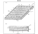
- FIG. 32A is a perspective view of still another display device with a touch panel 1J according to Embodiment 6, and FIG. 32B is a schematic cross-sectional view of the display device with touch panel 1J.
- the display device with touch panel 1J includes a capacitive touch panel 4J.
- the capacitive touch panel 4J is arranged parallel to each other and driven by a driving voltage, and is arranged parallel to each other so as to intersect the plurality of transmitting electrodes T, and is driven by the driving voltage.
- a plurality of strip-shaped receiving electrodes R for reading out signals based on the capacitance between the transmitting electrodes T and the transmitting electrodes T are provided on the display panel.
- the capacitive touch panel 4J is disposed between the casing transmission electrode HT continuously formed along the four side walls of the casing 3 and driven by the driving voltage, and between the transmission electrode T and the casing transmission electrode HT.
- a pressure-responsive material 14 that reacts with pressure.
- the transmission electrode T and the reception electrode R are formed on the same substrate on the display panel, the electrode thickness, the distance between the electrodes, and the capacitance are fixed.
- the pressure-responsive material 14 that reacts with pressure is disposed between the housing transmission electrode HT and the transmission electrode T.
- the electrostatic capacitance between the housing transmission electrode HT and the reception electrode R changes depending on the pressure reaction material 14 that reacts to pressure. Therefore, by reading and analyzing the signal based on the capacitance between the housing transmission electrode HT and the reception electrode R, which changes depending on the pressure reaction material 14, through the reception electrode R, the capacitance type touch panel 4J The acting pressure can be detected.
- FIG. 32A is a perspective view of still another display device 1K with a touch panel according to Embodiment 8
- FIG. 32B is a schematic cross-sectional view of the display device 1K with a touch panel
- FIG. 32C is a display device with a touch panel.
- 1 is a block diagram showing the relationship between a loop antenna, an NFC (Near Field Communication), and an amplifier 12K (sense circuit) provided in 1K.
- the touch panel-equipped display device 1K includes a capacitive touch panel 4K and a touch panel controller 10K that controls the capacitive touch panel 4K.
- the capacitive touch panel 4K includes a casing transmission electrode HKT that is formed in a loop shape along the four side walls of the casing 3 and is driven by a driving voltage.
- the touch panel controller 10K is connected to the NFC reader 16, the amplifier 12K that amplifies the signal read from the reception electrode R, and the housing transmission electrode HKT to the NFC reader 16 or the amplifier 12K. Switch 15 is provided.
- the NFC antenna is provided separately from the capacitive touch panel.
- the switch 15 when the switch 15 is switched to connect the housing transmission electrode HKT to the NFC reader 16, the housing transmission electrode HKT functions as an NFC antenna. For this reason, it is not necessary to separately provide an NFC antenna.
- a transmission electrode (enclosure transmission electrode) is provided on the enclosure.
- the present invention is not limited to this. You may comprise so that a receiving electrode (housing receiving electrode) may be provided in a housing, and you may comprise so that both a transmitting electrode (housing transmitting electrode) and a receiving electrode (housing receiving electrode) may be provided in a housing, It is only necessary that at least one of the transmission electrode (housing transmission electrode) and the receiving electrode (housing receiving electrode) is provided on the housing.
- a display device with a touch panel 1 includes a display panel (liquid crystal panel 2), a touch panel (capacitive touch panel 4) for operating the display panel (liquid crystal panel 2), and the touch panel ( A display device with a touch panel 1 including a controller (touch panel controller 10) for controlling a capacitive touch panel 4), wherein the touch panel (capacitive touch panel 4) is driven by a driving voltage. And a first reception electrode SA for reading a first signal based on a first capacitance between the transmission electrode T and the transmission electrode T, and a position farther from the transmission electrode T than the first reception electrode SA.
- the second capacitance between the second reception electrode and the transmission electrode disposed at a position farther from the transmission electrode than the first reception electrode is increased. Increase the frequency for reading the second signal based on. For this reason, it is possible to accurately detect the touch position on the touch panel where water droplets are present.
- the controller may increase the frequency by shortening a sampling time for reading the second signal. Good.
- the frequency for reading the second signal can be increased with a simple configuration.
- the display device with a touch panel 1 according to aspect 3 of the present invention is the above-described aspect 1, wherein the controller (touch panel controller 10) is configured such that when the water droplet is present on the touch panel (capacitive touch panel 4), the first The frequency for reading the signal may be increased.
- the touch position on the touch panel where water droplets are present can be detected more accurately.
- the first reception electrode SA may be shielded when a water droplet is present on the touch panel (the liquid crystal panel 2) in the aspect 1.
- the touch position on the touch panel where water droplets are present can be detected more accurately.
- the touch panel-equipped display device 1 further includes the housing 3 for housing the display panel (liquid crystal panel 2) in the first embodiment, and the second receiving electrode SB is disposed on the housing 3. Also good.
- the touch position on the housing can be accurately detected even when water droplets are present in the housing that houses the display panel.
- the second reception electrode SB is disposed on a side surface of the housing 3 in the aspect 5, and the transmission electrode T and the first reception electrode SB are the display panel. You may arrange
- the touch to the side surface of a housing is detected based on the change of the electrostatic capacitance between a transmission electrode and a 2nd receiving electrode, and the touch to the surface to a display panel is a 1st electrode with a transmission electrode. It can detect based on the change of the electrostatic capacitance between receiving electrodes.
- the second receiving electrode housing reception
- the wiring 19 arranged on the surface of the display panel liquid crystal panel 2
- Electrode Electrode
- the second receiving electrode arranged on the housing can be connected to the controller through the wiring arranged on the surface of the display panel.
- the touch panel-equipped display device 1 according to an aspect 8 of the present invention is the above aspect 1, wherein the transmission electrode T, the first reception electrode SA, and the second reception electrode SB are on the surface of the display panel (liquid crystal panel 2). May be arranged.
- the touch position on the housing can be accurately detected even when water droplets are present on the surface of the display panel.
- a display device with a touch panel 1 is the above-described aspect 8, wherein the transmission electrode T is formed in parallel with each other along a first direction, and the first reception electrode SA is the transmission electrode.
- the touch signal detection sensitivity is improved by meshing the first reception protrusion pattern and the second reception protrusion pattern.
- the controller (the touch panel controller 10) according to the aspect 1 is configured such that the controller (the touch panel controller 10) corresponds to the approach of the detection target to the touch panel (the capacitive touch panel 4). It may be determined whether the detection object is a conductive material or a non-conductive material based on a change characteristic of one capacitance and a change characteristic of the second capacitance.
- a detection target object is a conductive material or a non-conductive material, for example, the touch by a bare finger and the touch by the finger
- the first capacitance and the second capacitance are reduced according to the approach. If the detection object is a non-conductive object, the first capacitance may decrease and the second capacitance may increase in accordance with the approach.
- the detection target is a conductive material or a non-conductive material by a simple algorithm.
- Display device with touch panel Liquid crystal panel (display panel) 3 Housing 4 Capacitive touch panel (touch panel) 10 Touch panel controller (controller) T Transmitting electrode SA First receiving electrode SB Second receiving electrode W Water droplet
Landscapes
- Engineering & Computer Science (AREA)
- General Engineering & Computer Science (AREA)
- Theoretical Computer Science (AREA)
- Physics & Mathematics (AREA)
- General Physics & Mathematics (AREA)
- Human Computer Interaction (AREA)
- Nonlinear Science (AREA)
- Mathematical Physics (AREA)
- Chemical & Material Sciences (AREA)
- Crystallography & Structural Chemistry (AREA)
- Optics & Photonics (AREA)
- Position Input By Displaying (AREA)
Abstract
Selon l'invention, afin de détecter de manière précise une position tactile sur un panneau tactile sur lequel des gouttelettes d'eau sont présentes, ce dispositif d'affichage est pourvu d'un panneau tactile (1) qui comprend un panneau tactile (4) et un dispositif de commande de panneau tactile (10), le panneau tactile (4) comprenant une électrode de transmission (T), une première électrode de réception (SA) permettant de lire un premier signal sur la base d'une première électro-capacité avec une électrode de transmission (T), et une seconde électrode de réception (SB) positionnée à une distance plus éloignée de l'électrode de transmission (T) que la première électrode de réception (SA), et permettant de lire un second signal sur la base d'une seconde électro-capacité avec l'électrode de transmission (T). Le dispositif de commande (10) amplifie la fréquence de façon à lire le second signal lorsque des gouttelettes d'eau sont présentes sur le panneau tactile (4).
Priority Applications (2)
| Application Number | Priority Date | Filing Date | Title |
|---|---|---|---|
| CN201780016420.0A CN109074188A (zh) | 2016-03-30 | 2017-03-24 | 附有触摸屏的显示装置 |
| US16/086,602 US20190050097A1 (en) | 2016-03-30 | 2017-03-24 | Touch panel-equipped display device |
Applications Claiming Priority (2)
| Application Number | Priority Date | Filing Date | Title |
|---|---|---|---|
| JP2016-068576 | 2016-03-30 | ||
| JP2016068576 | 2016-03-30 |
Publications (1)
| Publication Number | Publication Date |
|---|---|
| WO2017170224A1 true WO2017170224A1 (fr) | 2017-10-05 |
Family
ID=59964561
Family Applications (1)
| Application Number | Title | Priority Date | Filing Date |
|---|---|---|---|
| PCT/JP2017/012011 Ceased WO2017170224A1 (fr) | 2016-03-30 | 2017-03-24 | Dispositif d'affichage pourvu d'un panneau tactile |
Country Status (3)
| Country | Link |
|---|---|
| US (1) | US20190050097A1 (fr) |
| CN (1) | CN109074188A (fr) |
| WO (1) | WO2017170224A1 (fr) |
Cited By (4)
| Publication number | Priority date | Publication date | Assignee | Title |
|---|---|---|---|---|
| US20190018529A1 (en) * | 2017-07-12 | 2019-01-17 | Japan Display Inc. | Display device |
| TWI682317B (zh) * | 2018-05-31 | 2020-01-11 | 奕力科技股份有限公司 | 互容式觸控面板 |
| CN112470168A (zh) * | 2018-07-30 | 2021-03-09 | 德克萨斯仪器股份有限公司 | 使用从动屏蔽件和触摸元件锁定算法 |
| US11042245B2 (en) | 2018-08-22 | 2021-06-22 | ILI Technology Holding Corporation | Mutual capacitive touch panel |
Families Citing this family (9)
| Publication number | Priority date | Publication date | Assignee | Title |
|---|---|---|---|---|
| CN108803945B (zh) * | 2018-09-05 | 2024-04-12 | 京东方科技集团股份有限公司 | 一种触摸屏及显示设备 |
| CN111610873B (zh) * | 2019-02-26 | 2023-10-27 | 敦泰电子有限公司 | 触控控制方法、电路系统及触控装置 |
| JP7135964B2 (ja) * | 2019-03-26 | 2022-09-13 | 株式会社デンソー | ヒータ装置 |
| US10996807B2 (en) * | 2019-05-24 | 2021-05-04 | Korea University Research And Business Foundation | Touch sensor with modular shape and display device including the same |
| CN110174972B (zh) * | 2019-06-04 | 2022-10-18 | 业成科技(成都)有限公司 | 触控系统、操作方法以及非暂态电脑可读取记录媒体 |
| JP7383869B2 (ja) * | 2020-02-13 | 2023-11-21 | シャープ株式会社 | タッチパネル及び表示装置 |
| WO2022226245A1 (fr) * | 2021-04-23 | 2022-10-27 | Ventiva, Inc. | Transfert de chaleur à l'aide de pompes ioniques |
| CN113934326B (zh) * | 2021-10-20 | 2025-04-01 | 北京集创北方科技股份有限公司 | 一种触控点的过滤方法及装置、电子设备、存储介质 |
| KR20250035693A (ko) * | 2023-09-05 | 2025-03-13 | 삼성디스플레이 주식회사 | 터치 패널 및 이를 포함하는 표시 장치 |
Citations (3)
| Publication number | Priority date | Publication date | Assignee | Title |
|---|---|---|---|---|
| JP2013125496A (ja) * | 2011-12-16 | 2013-06-24 | Mitsubishi Electric Corp | タッチパネルおよび表示装置 |
| US20150179122A1 (en) * | 2013-12-20 | 2015-06-25 | Sharp Kabushiki Kaisha | Discriminative capacitive touch panel |
| JP2015176171A (ja) * | 2014-03-13 | 2015-10-05 | パナソニックIpマネジメント株式会社 | 静電検出センサ |
Family Cites Families (3)
| Publication number | Priority date | Publication date | Assignee | Title |
|---|---|---|---|---|
| JP5962907B2 (ja) * | 2011-07-06 | 2016-08-03 | パナソニックIpマネジメント株式会社 | 電子機器 |
| CN104423736A (zh) * | 2013-08-29 | 2015-03-18 | 天津富纳源创科技有限公司 | 触摸屏触摸识别方法 |
| CN105094490B (zh) * | 2015-08-24 | 2019-01-08 | 上海天马微电子有限公司 | 触摸显示面板、触摸显示装置及其触控方法 |
-
2017
- 2017-03-24 WO PCT/JP2017/012011 patent/WO2017170224A1/fr not_active Ceased
- 2017-03-24 CN CN201780016420.0A patent/CN109074188A/zh active Pending
- 2017-03-24 US US16/086,602 patent/US20190050097A1/en not_active Abandoned
Patent Citations (3)
| Publication number | Priority date | Publication date | Assignee | Title |
|---|---|---|---|---|
| JP2013125496A (ja) * | 2011-12-16 | 2013-06-24 | Mitsubishi Electric Corp | タッチパネルおよび表示装置 |
| US20150179122A1 (en) * | 2013-12-20 | 2015-06-25 | Sharp Kabushiki Kaisha | Discriminative capacitive touch panel |
| JP2015176171A (ja) * | 2014-03-13 | 2015-10-05 | パナソニックIpマネジメント株式会社 | 静電検出センサ |
Cited By (5)
| Publication number | Priority date | Publication date | Assignee | Title |
|---|---|---|---|---|
| US20190018529A1 (en) * | 2017-07-12 | 2019-01-17 | Japan Display Inc. | Display device |
| US10564754B2 (en) * | 2017-07-12 | 2020-02-18 | Japan Display Inc. | Display device |
| TWI682317B (zh) * | 2018-05-31 | 2020-01-11 | 奕力科技股份有限公司 | 互容式觸控面板 |
| CN112470168A (zh) * | 2018-07-30 | 2021-03-09 | 德克萨斯仪器股份有限公司 | 使用从动屏蔽件和触摸元件锁定算法 |
| US11042245B2 (en) | 2018-08-22 | 2021-06-22 | ILI Technology Holding Corporation | Mutual capacitive touch panel |
Also Published As
| Publication number | Publication date |
|---|---|
| US20190050097A1 (en) | 2019-02-14 |
| CN109074188A (zh) | 2018-12-21 |
Similar Documents
| Publication | Publication Date | Title |
|---|---|---|
| WO2017170224A1 (fr) | Dispositif d'affichage pourvu d'un panneau tactile | |
| US10353485B1 (en) | Multifunction input device with an embedded capacitive sensing layer | |
| US20060132332A1 (en) | Capacitive input device | |
| KR101871258B1 (ko) | 정전용량성 센서 디바이스용 전극 구조 및 접근 검출용 정전용량성 센서 디바이스 | |
| EP2159669B1 (fr) | Stylet électromagnétique pour faire fonctionner un panneau tactile capacitif | |
| US9189089B2 (en) | Pointing device with prevention of unintended input | |
| TW200915161A (en) | Two-dimensional position sensor | |
| KR101951353B1 (ko) | 위치 검출용 용량성 센서 디바이스를 위한 전극 디바이스 | |
| US10430008B2 (en) | Methods and apparatus for a 3-dimensional capacitive sensor having multi-operation electrodes | |
| KR101867502B1 (ko) | 용량성 센서 장치 및 입력 장치를 동작시키기 위한 방법 | |
| CA3028811A1 (fr) | Dispositif et procede de capteur tactile | |
| WO2012177369A1 (fr) | Intégration de capteur tactile et d'antenne le long d'un boîtier de dispositif électronique | |
| JP5796527B2 (ja) | 静電容量式タッチパネル | |
| US9300289B2 (en) | Switch device | |
| JP2009026151A (ja) | 入力装置及び電子機器 | |
| KR101573521B1 (ko) | 필압의 감지가 가능한 터치 펜 | |
| JP4750629B2 (ja) | 位置検出装置及び位置検出用センス部品 | |
| KR20110094568A (ko) | 정전용량 감지형 터치스위치 | |
| US10976876B2 (en) | Conductive guides for proximity sensing devices | |
| WO2017170262A1 (fr) | Dispositif d'affichage équipé d'un panneau tactile | |
| JP2011215675A (ja) | 静電容量方式タッチパネル | |
| US10275090B2 (en) | Method and apparatus for ghosting suppression in capacitive key matrix and touch pads | |
| JP2007122891A (ja) | タッチキーとそれを用いた電気機器 | |
| KR20150085396A (ko) | 터치 기능을 구비한 복합 입력장치 | |
| KR20150051719A (ko) | 터치패널센서 |
Legal Events
| Date | Code | Title | Description |
|---|---|---|---|
| NENP | Non-entry into the national phase |
Ref country code: DE |
|
| 121 | Ep: the epo has been informed by wipo that ep was designated in this application |
Ref document number: 17774761 Country of ref document: EP Kind code of ref document: A1 |
|
| 122 | Ep: pct application non-entry in european phase |
Ref document number: 17774761 Country of ref document: EP Kind code of ref document: A1 |
|
| NENP | Non-entry into the national phase |
Ref country code: JP |