WO2017170464A1 - Système de gestion, procédé de gestion, appareil, et dispositif de gestion - Google Patents
Système de gestion, procédé de gestion, appareil, et dispositif de gestion Download PDFInfo
- Publication number
- WO2017170464A1 WO2017170464A1 PCT/JP2017/012503 JP2017012503W WO2017170464A1 WO 2017170464 A1 WO2017170464 A1 WO 2017170464A1 JP 2017012503 W JP2017012503 W JP 2017012503W WO 2017170464 A1 WO2017170464 A1 WO 2017170464A1
- Authority
- WO
- WIPO (PCT)
- Prior art keywords
- command
- property
- variable
- indicating
- specific value
- Prior art date
- Legal status (The legal status is an assumption and is not a legal conclusion. Google has not performed a legal analysis and makes no representation as to the accuracy of the status listed.)
- Ceased
Links
Images




Classifications
-
- H—ELECTRICITY
- H02—GENERATION; CONVERSION OR DISTRIBUTION OF ELECTRIC POWER
- H02J—ELECTRIC POWER NETWORKS; CIRCUIT ARRANGEMENTS OR SYSTEMS FOR SUPPLYING OR DISTRIBUTING ELECTRIC POWER; SYSTEMS FOR STORING ELECTRIC ENERGY
- H02J7/00—Circuit arrangements for charging or discharging batteries or for supplying loads from batteries
- H02J7/34—Parallel operation in networks using both storage and other DC sources, e.g. providing buffering
- H02J7/35—Parallel operation in networks using both storage and other DC sources, e.g. providing buffering with light sensitive cells
-
- H—ELECTRICITY
- H02—GENERATION; CONVERSION OR DISTRIBUTION OF ELECTRIC POWER
- H02J—ELECTRIC POWER NETWORKS; CIRCUIT ARRANGEMENTS OR SYSTEMS FOR SUPPLYING OR DISTRIBUTING ELECTRIC POWER; SYSTEMS FOR STORING ELECTRIC ENERGY
- H02J13/00—Circuit arrangements for providing remote monitoring or remote control of equipment in a power distribution network
- H02J13/13—Circuit arrangements for providing remote monitoring or remote control of equipment in a power distribution network characterised by the transmission of data to equipment in the power network
-
- H—ELECTRICITY
- H02—GENERATION; CONVERSION OR DISTRIBUTION OF ELECTRIC POWER
- H02J—ELECTRIC POWER NETWORKS; CIRCUIT ARRANGEMENTS OR SYSTEMS FOR SUPPLYING OR DISTRIBUTING ELECTRIC POWER; SYSTEMS FOR STORING ELECTRIC ENERGY
- H02J13/00—Circuit arrangements for providing remote monitoring or remote control of equipment in a power distribution network
- H02J13/13—Circuit arrangements for providing remote monitoring or remote control of equipment in a power distribution network characterised by the transmission of data to equipment in the power network
- H02J13/1331—Circuit arrangements for providing remote monitoring or remote control of equipment in a power distribution network characterised by the transmission of data to equipment in the power network using wireless data transmission
-
- H—ELECTRICITY
- H02—GENERATION; CONVERSION OR DISTRIBUTION OF ELECTRIC POWER
- H02J—ELECTRIC POWER NETWORKS; CIRCUIT ARRANGEMENTS OR SYSTEMS FOR SUPPLYING OR DISTRIBUTING ELECTRIC POWER; SYSTEMS FOR STORING ELECTRIC ENERGY
- H02J13/00—Circuit arrangements for providing remote monitoring or remote control of equipment in a power distribution network
- H02J13/14—Circuit arrangements for providing remote monitoring or remote control of equipment in a power distribution network the power network being locally controlled, e.g. home energy management systems [HEMS]
-
- H—ELECTRICITY
- H02—GENERATION; CONVERSION OR DISTRIBUTION OF ELECTRIC POWER
- H02J—ELECTRIC POWER NETWORKS; CIRCUIT ARRANGEMENTS OR SYSTEMS FOR SUPPLYING OR DISTRIBUTING ELECTRIC POWER; SYSTEMS FOR STORING ELECTRIC ENERGY
- H02J13/00—Circuit arrangements for providing remote monitoring or remote control of equipment in a power distribution network
- H02J13/18—Circuit arrangements for providing remote monitoring or remote control of equipment in a power distribution network characterised by the remotely-controlled equipment, e.g. converters or transformers
- H02J13/333—Circuit arrangements for providing remote monitoring or remote control of equipment in a power distribution network characterised by the remotely-controlled equipment, e.g. converters or transformers the equipment forming part of substations
-
- H—ELECTRICITY
- H02—GENERATION; CONVERSION OR DISTRIBUTION OF ELECTRIC POWER
- H02J—ELECTRIC POWER NETWORKS; CIRCUIT ARRANGEMENTS OR SYSTEMS FOR SUPPLYING OR DISTRIBUTING ELECTRIC POWER; SYSTEMS FOR STORING ELECTRIC ENERGY
- H02J3/00—Circuit arrangements for AC mains or AC distribution networks
- H02J3/12—Arrangements for adjusting voltage in AC networks by changing a characteristic of the network load
- H02J3/14—Arrangements for adjusting voltage in AC networks by changing a characteristic of the network load by switching loads on to, or off from, the networks, e.g. progressively balanced loading
-
- H—ELECTRICITY
- H04—ELECTRIC COMMUNICATION TECHNIQUE
- H04M—TELEPHONIC COMMUNICATION
- H04M11/00—Telephonic communication systems specially adapted for combination with other electrical systems
-
- H—ELECTRICITY
- H04—ELECTRIC COMMUNICATION TECHNIQUE
- H04Q—SELECTING
- H04Q9/00—Arrangements in telecontrol or telemetry systems for selectively calling a substation from a main station, in which substation desired apparatus is selected for applying a control signal thereto or for obtaining measured values therefrom
-
- H—ELECTRICITY
- H02—GENERATION; CONVERSION OR DISTRIBUTION OF ELECTRIC POWER
- H02J—ELECTRIC POWER NETWORKS; CIRCUIT ARRANGEMENTS OR SYSTEMS FOR SUPPLYING OR DISTRIBUTING ELECTRIC POWER; SYSTEMS FOR STORING ELECTRIC ENERGY
- H02J2105/00—Networks for supplying or distributing electric power characterised by their spatial reach or by the load
- H02J2105/10—Local stationary networks having a local or delimited stationary reach
- H02J2105/12—Local stationary networks having a local or delimited stationary reach supplying households or buildings
-
- H—ELECTRICITY
- H02—GENERATION; CONVERSION OR DISTRIBUTION OF ELECTRIC POWER
- H02J—ELECTRIC POWER NETWORKS; CIRCUIT ARRANGEMENTS OR SYSTEMS FOR SUPPLYING OR DISTRIBUTING ELECTRIC POWER; SYSTEMS FOR STORING ELECTRIC ENERGY
- H02J3/00—Circuit arrangements for AC mains or AC distribution networks
- H02J3/28—Arrangements for balancing of the load in networks by storage of energy
- H02J3/32—Arrangements for balancing of the load in networks by storage of energy using batteries or super capacitors with converting means
-
- Y—GENERAL TAGGING OF NEW TECHNOLOGICAL DEVELOPMENTS; GENERAL TAGGING OF CROSS-SECTIONAL TECHNOLOGIES SPANNING OVER SEVERAL SECTIONS OF THE IPC; TECHNICAL SUBJECTS COVERED BY FORMER USPC CROSS-REFERENCE ART COLLECTIONS [XRACs] AND DIGESTS
- Y02—TECHNOLOGIES OR APPLICATIONS FOR MITIGATION OR ADAPTATION AGAINST CLIMATE CHANGE
- Y02B—CLIMATE CHANGE MITIGATION TECHNOLOGIES RELATED TO BUILDINGS, e.g. HOUSING, HOUSE APPLIANCES OR RELATED END-USER APPLICATIONS
- Y02B90/00—Enabling technologies or technologies with a potential or indirect contribution to GHG emissions mitigation
- Y02B90/20—Smart grids as enabling technology in buildings sector
-
- Y—GENERAL TAGGING OF NEW TECHNOLOGICAL DEVELOPMENTS; GENERAL TAGGING OF CROSS-SECTIONAL TECHNOLOGIES SPANNING OVER SEVERAL SECTIONS OF THE IPC; TECHNICAL SUBJECTS COVERED BY FORMER USPC CROSS-REFERENCE ART COLLECTIONS [XRACs] AND DIGESTS
- Y04—INFORMATION OR COMMUNICATION TECHNOLOGIES HAVING AN IMPACT ON OTHER TECHNOLOGY AREAS
- Y04S—SYSTEMS INTEGRATING TECHNOLOGIES RELATED TO POWER NETWORK OPERATION, COMMUNICATION OR INFORMATION TECHNOLOGIES FOR IMPROVING THE ELECTRICAL POWER GENERATION, TRANSMISSION, DISTRIBUTION, MANAGEMENT OR USAGE, i.e. SMART GRIDS
- Y04S40/00—Systems for electrical power generation, transmission, distribution or end-user application management characterised by the use of communication or information technologies, or communication or information technology specific aspects supporting them
- Y04S40/12—Systems for electrical power generation, transmission, distribution or end-user application management characterised by the use of communication or information technologies, or communication or information technology specific aspects supporting them characterised by data transport means between the monitoring, controlling or managing units and monitored, controlled or operated electrical equipment
-
- Y—GENERAL TAGGING OF NEW TECHNOLOGICAL DEVELOPMENTS; GENERAL TAGGING OF CROSS-SECTIONAL TECHNOLOGIES SPANNING OVER SEVERAL SECTIONS OF THE IPC; TECHNICAL SUBJECTS COVERED BY FORMER USPC CROSS-REFERENCE ART COLLECTIONS [XRACs] AND DIGESTS
- Y04—INFORMATION OR COMMUNICATION TECHNOLOGIES HAVING AN IMPACT ON OTHER TECHNOLOGY AREAS
- Y04S—SYSTEMS INTEGRATING TECHNOLOGIES RELATED TO POWER NETWORK OPERATION, COMMUNICATION OR INFORMATION TECHNOLOGIES FOR IMPROVING THE ELECTRICAL POWER GENERATION, TRANSMISSION, DISTRIBUTION, MANAGEMENT OR USAGE, i.e. SMART GRIDS
- Y04S40/00—Systems for electrical power generation, transmission, distribution or end-user application management characterised by the use of communication or information technologies, or communication or information technology specific aspects supporting them
- Y04S40/12—Systems for electrical power generation, transmission, distribution or end-user application management characterised by the use of communication or information technologies, or communication or information technology specific aspects supporting them characterised by data transport means between the monitoring, controlling or managing units and monitored, controlled or operated electrical equipment
- Y04S40/126—Systems for electrical power generation, transmission, distribution or end-user application management characterised by the use of communication or information technologies, or communication or information technology specific aspects supporting them characterised by data transport means between the monitoring, controlling or managing units and monitored, controlled or operated electrical equipment using wireless data transmission
Definitions
- the present invention relates to a management system, a management method, a device, and a management apparatus.
- the devices are, for example, home electric appliances such as air conditioners and lighting devices, and distributed power sources such as solar cells, storage batteries, and fuel power generation devices.
- Management device for example, HEMS (Home Energy Management System), SEMS (Store Energy Management System), BEMS (Building Energy Management System), FEMS (Factory Energy Management System), referred to as CEMS (Cluster / Community Energy Management System) Is done.
- the management system includes equipment and a management device.
- the management apparatus includes a transmission unit that transmits a first command that instructs an operation of the device to the device.
- the device includes a control unit that controls the operation of the device according to the first command, and a transmission unit that transmits a response command including a property indicating a state of the device to the management apparatus.
- the property of the first command includes a variable property indicating a variable that can be changed by the operation of the device.
- the control unit maintains the variable indicated by the variable property without being changed when the operation instructed by the first command is continued.
- the transmission unit provided in the device transmits the response command including, as the variable property, a specific value specifying whether or not the device is operating according to the first command.
- the management method includes: a step A for transmitting a first command for instructing an operation of the device from a management device to the device; a step B for controlling the operation of the device according to the first command; And a step C of transmitting a response command including a property indicating a state of the device from the device to the management apparatus.
- the property of the first command includes a variable property indicating a variable that can be changed by the operation of the device.
- the step B includes a step of maintaining the variable indicated by the variable property without being changed when the operation instructed by the first command is continued.
- the step C includes a step of transmitting the response command including, as the variable property, a specific value that specifies whether or not the operation is performed according to the first command.
- the Equipment is managed by a management device.
- the device includes a control unit that controls the operation of the device according to a first command received from the management device, and a transmission unit that transmits a response command including a property indicating a state of the device to the management device.
- the property of the first command includes a variable property indicating a variable that can be changed by the operation of the device.
- the control unit maintains the variable indicated by the variable property without being changed when the operation instructed by the first command is continued.
- the transmission unit transmits the response command including, as the variable property, a specific value that specifies whether the operation is performed according to the first command.
- the management apparatus includes a transmission unit that transmits a first command that instructs the operation of the device to the device, and a reception unit that receives a response command including a property indicating a state of the device from the device.
- the property of the first command includes a variable property indicating a variable that can be changed by the operation of the device.
- the variable indicated by the variable property is maintained without being changed when the operation indicated by the first command is continued.
- the receiving unit receives the response command including, as the variable property, a specific value that specifies whether or not the device is operating according to the first command.
- FIG. 1 is a diagram illustrating a management system 1 according to the embodiment.
- FIG. 2 is a diagram illustrating the communication device 132 according to the embodiment.
- FIG. 3 is a diagram illustrating the EMS 160 according to the embodiment.
- FIG. 4 is a diagram illustrating an example of a SET command according to the embodiment.
- FIG. 5 is a diagram illustrating an example of a SET response command according to the embodiment.
- FIG. 6 is a diagram illustrating an example of a SET command according to the embodiment.
- FIG. 7 is a diagram illustrating an example of a SET response command according to the embodiment.
- FIG. 8 is a sequence diagram illustrating a management method according to the embodiment.
- FIG. 9 is a sequence diagram illustrating a management method according to the embodiment.
- FIG. 10 is a sequence diagram illustrating a management method according to the embodiment.
- FIG. 11 is a sequence diagram illustrating a management method according to the first modification.
- FIG. 12 is a sequence diagram
- the management system 1 includes a facility 100 and an external server 400.
- the facility 100 has a router 200.
- the router 200 is connected to the external server 400 via the network 300.
- the router 200 forms a local area network and is connected to each device (for example, the communication device 132 of the PCS 130, the load 150, the EMS 160, the display device 170, and the like).
- a solid line indicates a power line
- a dotted line indicates a signal line. Note that the present invention is not limited to this, and a signal may be transmitted through a power line.
- the facility 100 includes a solar battery 110, a storage battery 120, a PCS 130, a distribution board 140, a load 150, an EMS 160, and a display device 170.
- the solar cell 110 is a device that generates power in response to light reception.
- the solar cell 110 outputs the generated DC power.
- the amount of power generated by the solar cell 110 changes according to the amount of solar radiation irradiated on the solar cell 110.
- the solar cell 110 is an example of a distributed power source that can be output-suppressed based on output suppression specified by the operator, but is not limited thereto, and the storage battery 120 is an output suppression specified by the operator. It may be a distributed power source whose output can be suppressed based on the above.
- Storage battery 120 is a device that stores electric power.
- the storage battery 120 outputs the accumulated DC power.
- the storage battery 120 is an example of a distributed power source that cannot be output-suppressed based on output suppression specified by the operator.
- the PCS 130 is an example of a power conversion system (PCS; Power Conditioning System) that converts output power from a distributed power source.
- PCS Power conversion system
- the PCS 130 includes a conversion device 131 and a communication device 132.
- the conversion device 131 converts DC power from the solar battery 110 into AC power, and converts DC power from the storage battery 120 into AC power. Furthermore, the converter 131 converts AC power from the power system 10 into DC power.
- the converter 131 is connected to the main power line 10L (here, the main power line 10LA and the main power line 10LB) connected to the power system 10 via the first distribution board 140A, and both the solar battery 110 and the storage battery 120 are connected. Connected to.
- the main power line 10LA is a power line that connects the power system 10 and the first distribution board 140A
- the main power line 10LB is a power line that connects the first distribution board 140A and the second distribution board 140B.
- the conversion device 131 is described as a hybrid power conversion device connected to the solar cell 110 and the storage battery 120, but the power conversion device is connected to each of the solar cell 110 and the storage battery 120. It may be configured.
- the communication device 132 is connected to the conversion device 131, receives various messages to the conversion device 131, and transmits various messages from the conversion device 131.
- a protocol for example, a unique protocol
- PCS 130 In communication between the communication device 132 and the conversion device 131, a protocol (for example, a unique protocol) applied to the PCS 130 is used.
- the communication device 132 is connected to the router 200 by wire or wireless.
- the communication device 132 is connected to the external server 400 via the router 200, and receives an output suppression message from the external server 400 that instructs to suppress the output of the distributed power supply.
- the communication device 132 is connected to the EMS 160 via the router 200, and performs communication of a predetermined command having a predetermined format with the EMS 160.
- the predetermined format is not particularly limited, and for example, the ECHONET Lite system, the SEP2.0 system, the KNX system, or the like can be used.
- the predetermined command can be roughly classified into, for example, a request command, a request response command that is a response to the request command, or an information notification command.
- the request command is, for example, a SET command or a GET command.
- the request response command is, for example, a SET response command that is a response to the SET command, a GET response command that is a response to the GET command, or the like.
- the information notification command is, for example, an INF command.
- the SET command is a command including a property for instructing setting or operation for the PCS 130.
- the SET response command is a command indicating that the SET command has been received.
- the GET command includes a property indicating the state of the PCS 130, and is a command for acquiring the state of the PCS 130.
- the GET response command includes a property indicating the state of the PCS 130 and includes information requested by the GET command.
- the INF command includes a property indicating the state of the PCS 130 and is a command for notifying the state of the PCS 130.
- the distribution board 140 is connected to the main power line 10L.
- the distribution board 140 includes a first distribution board 140A and a second distribution board 140B.
- the first distribution board 140A is connected to the power system 10 via the main power line 10LA and is connected to the solar battery 110 and the storage battery 120 via the converter 131. Further, the first distribution board 140A controls the power output from the converter 131 and the power supplied from the power system 10 to flow to the main power line 10LB.
- the power flowing from the main power line 10LB is distributed to each device (here, the load 150 and the EMS 160) by the second distribution board 140B.
- the load 150 is a device that consumes power supplied through the power line.
- the load 150 includes devices such as an air conditioner, a lighting device, a refrigerator, and a television.
- the load 150 may be a single device or may include a plurality of devices.
- the EMS 160 is an apparatus (EMS; Energy Management System) that manages power information indicating power in the facility 100.
- the power in the facility 100 refers to power flowing through the facility 100, power purchased by the facility 100, power sold from the facility 100, and the like. Therefore, for example, the EMS 160 manages at least the PCS 130.
- the EMS 160 may control the power generation amount of the solar battery 110, the charge amount of the storage battery 120, and the discharge amount of the storage battery 120.
- the EMS 160 may be configured integrally with the distribution board 140.
- the EMS 160 is a device connected to the network 300, and the function of the EMS 160 may be provided by a cloud service via the network 300.
- the EMS 160 is connected to each device (for example, the communication device 132 and the load 150 of the PCS 130) via the router 200, and performs communication of a predetermined command having a predetermined format with each device.
- the EMS 160 is connected to the display device 170 via the router 200 and communicates with the display device 170.
- the EMS 160 may perform communication of a predetermined command having a predetermined format with the display device 170.
- the predetermined format is, for example, a format that conforms to the ECHONET Lite system.
- the display device 170 displays power information indicating the power in the facility 100.
- the display device 170 is, for example, a smartphone, a tablet, a digital television, or a dedicated terminal.
- the display device 170 is connected to the EMS 160 by wire or wireless and communicates with the EMS 160.
- the display device 170 may perform communication of a predetermined command having a predetermined format with the EMS 160.
- the display device 170 receives data necessary for displaying power information from the EMS 160.
- the network 300 is a communication network that connects the EMS 160 and the external server 400.
- the network 300 may be the Internet.
- the network 300 may include a mobile communication network.
- the network 300 may be a dedicated communication line or a general communication line. For example, when the output of the solar battery 110 is greater than or equal to a predetermined output, the output can be more reliably suppressed by using a dedicated communication line as the network 300.
- the external server 400 is a server managed by a business operator such as a power generation business, a power transmission / distribution business, or a retail business.
- the operator designates output suppression of the distributed power supply.
- the external server 400 transmits an output suppression message that instructs to suppress output of the distributed power supply.
- the external server 400 may transmit a command (DR; Demand Response) that instructs the facility 100 to suppress the tidal flow rate from the power system 10.
- DR Demand Response
- the output suppression message includes a target output suppression level indicating the level of output suppression of the distributed power supply (in this case, the solar battery 110).
- the target output suppression level is determined in accordance with an output (hereinafter, equipment certified output) that has been certified as an output capability (for example, a rated output) of the PCS that controls the distributed power supply.
- the target output suppression level may be expressed by an absolute value (for example, XX kW) determined according to the facility certified output, or may be expressed by a relative value (for example, a decrease in XX kW) with respect to the facility certified output.
- a suppression ratio for example, OO%) with respect to the equipment certified output.
- equipment authorization capacity [kWh] may be sufficient.
- the equipment certified output is set to the smaller output capability of these output capabilities.
- the facility authorization output is the sum of the output capacities of the plurality of PCSs.
- the output suppression message includes calendar information indicating a schedule of output suppression of the distributed power supply.
- the schedule for suppressing the output of the distributed power supply can be set in units of 30 minutes.
- the calendar information may include a schedule for one day, a schedule for one month, or a schedule for one year.
- a predetermined period may be set as the maximum period during which the output of the distributed power source is suppressed.
- the predetermined time may be, for example, the number of days in one year (days rule) or the accumulated time in one year (cumulative time rule). More specifically, for example, the predetermined period may be 30 days in one year (30 day rule), or 360 hours in one year (360 hour rule). However, the predetermined period may not be determined (specified rule).
- variable properties indicating variables that can be changed by the operation of the device, such as a storage battery charge amount setting value and a discharge amount setting value.
- the PCS 130 is mainly exemplified as a device.
- the EMS 160 acquires a variable property from the PCS 130 by transmitting a second command (for example, a GET command) after transmitting a first command (for example, a SET command) under such a premise.
- a second command for example, a GET command
- a first command for example, a SET command
- the PCS 130 transmits the variable after being changed by the operation of the PCS 130 according to the second command
- the EMS 160 cannot grasp whether the PCS 130 is operating according to the first command transmitted by itself.
- the PCS 130 is configured not to change the variable indicated by the variable property until the operation designated by the first command is completed.
- the EMS 160 since the variable is not changed, even if the EMS 160 receives a response command to the second command, the EMS 160 knows whether the PCS 130 is operating according to the first command. Cause an event that cannot be performed.
- the EMS 160 transmits a first command instructing the operation of the PCS 130 to the PCS 130, and transmits a second command requesting the state of the PCS 130 to the PCS 130.
- the PCS 130 controls the operation of the PCS 130 according to the first command.
- the PCS 130 transmits a response command (for example, a GET response command) including a property indicating the state of the PCS 130 to the EMS 160.
- the properties of the first command and the second command include a variable property indicating a variable that can be changed by the operation of the PCS 130.
- the PCS 130 maintains the variable indicated by the variable property without being changed until the operation designated by the first command is completed.
- the PCS 130 transmits a response command including, as a variable property, a specific value that specifies whether the operation is performed according to the first command.
- This response command is a request response command including a SET response command and a GET response command, or an information notification command including an INF command.
- the specific value may include a first specific value indicating that the operation instructed by the first command is completed. That is, when the operation designated by the first command is completed, the PCS 130 transmits a second command including a variable property indicating the first specific value to the EMS 160.
- the first specific value may be different from the value that can be indicated by the variable property included in the first command.
- the first specific value may be a value associated with the operation completion, or may be zero.
- the specific value may include a second specific value indicating that the operation instructed by the first command has been canceled by the user.
- the PCS 130 transmits a second command including a variable property indicating the second specific value to the EMS 160.
- the second specific value may be different from the value that can be indicated by the variable property included in the first command.
- the second specific value may be a value associated with the operation cancellation or may be zero.
- the specific value may include a third specific value indicating that the operation instructed by the first command has not been performed or that the operation instructed by the first command has been interrupted.
- the PCS 130 receives the second command including the variable property indicating the third specific value. Send to EMS 160.
- the third specific value may be different from a value that can be indicated by the variable property included in the first command.
- the third specific value may be a value associated with the operation non-execution or the operation interruption, or may be zero.
- the first specific value may be a value different from the second specific value and the third specific value.
- the first specific value may be the same value as the second specific value and the third specific value.
- the second specific value may be a value different from the first specific value and the third specific value.
- the second specific value may be the same value as the first specific value and the third specific value.
- the third specific value may be a value different from the first specific value and the second specific value.
- the third specific value may be the same value as the first specific value and the second specific value.
- the communication device 132 includes a first communication unit 132A, a second communication unit 132B, an interface 132C, and a control unit 132D.
- the communication device 132 (that is, the PCS 130) is an example of a device.
- the first communication unit 132A receives from the external server 400 an output suppression message that instructs output suppression of the distributed power supply. In the embodiment, the first communication unit 132A receives the output suppression message from the external server 400 without going through the EMS 160.
- the second communication unit 132B performs communication of a predetermined command having a predetermined format with the EMS 160.
- the predetermined format is, for example, a format that conforms to the ECHONET Lite system.
- the predetermined format used in communication between the communication device 132 (second communication unit 132B) and the EMS 160 may be different from the format used in communication between the communication device 132 (first communication unit 132A) and the external server 400. Good.
- the predetermined format used for communication between the second communication unit 132B (second communication unit 132B) and the EMS 160 may be different from the format used for communication between the communication device 132 (interface 132C) and the conversion device 131.
- the interface 132C is an interface with the conversion device 131.
- the interface 132C may be a wired interface or a wireless interface.
- a protocol for example, a unique protocol applied to the PCS 130 is used.
- the control unit 132D includes a memory and a CPU, and controls the communication device 132.
- the control unit 132D controls the output of the distributed power source according to the output suppression message by controlling the conversion device 131 using the interface 132C.
- Control part 132D acquires the state (For example, the electric power generation amount of the solar cell 110, the electrical storage amount of the storage battery 120, the discharge amount of the storage battery 120) from the conversion device 131 using the interface 132C.
- the control unit 132D generates a command for controlling the conversion device 131 based on the command received from the EMS 160, and outputs the command to the conversion device 131 using the interface 132C.
- the EMS 160 includes a communication unit 161 and a control unit 162.
- the communication unit 161 communicates with the communication device 132 for a predetermined command having a predetermined format.
- the predetermined format is, for example, a format that conforms to the ECHONET Lite system.
- the control unit 162 includes a memory and a CPU, and controls the EMS 160.
- the controller 162 may control the power generation amount of the solar battery 110, the charge amount of the storage battery 120, and the discharge amount of the storage battery 120.
- the SET command M510 includes a header M511, a code M512, and a target property M513.
- the SET command M510 is an example of a first command that instructs the operation of the PCS 130, and is a command transmitted from the EMS 160 to the PCS 130.
- the header M511 is information indicating the destination of the SET command M510.
- the code M512 is information indicating the type of message including the code M512.
- the code M512 is information indicating that the message including the code M512 is a SET command.
- the target property M513 includes a property indicating an operation that the EMS 160 instructs the PCS 130.
- a property includes, for example, a variable property indicating a variable that can be changed by the operation of the PCS 130.
- the variable property includes a set value property indicating a set value of the charge / discharge amount of the storage battery 120.
- the charge / discharge amount set value is a generic term for the charge amount set value or the discharge amount set value, and may be either one or both.
- the charge amount set value or the discharge amount set value may include information including the type of power.
- the type of electric power is alternating current (AC) or direct current (DC).
- the set value property may be, for example, a property that specifies the amount of electric power (Wh) for charging or discharging, or a property that specifies the capacity (Ah) of charging or discharging.
- Wh amount of electric power
- Ah capacity of charging or discharging.
- the setting value specified by the setting value property may be the instantaneous power (W) of charging or discharging.
- the SET response command M520 includes a header M521, a code M522, and a response content M523.
- the SET response command M520 is an example of a command transmitted from the PCS 130 to the EMS 160 in response to a command received from the EMS 160.
- the header M521 is information indicating the destination of the SET response command M520.
- the code M522 is information indicating the type of message including the code M522.
- the code M522 is information indicating that the message including the code M522 is a SET response command.
- the response content M523 includes information indicating that the SET command has been received. Such information may be a copy of the property included in the SET command, or may be an acknowledgment (ACK). Such information is not limited to this, and may be a response (Selective ACK) intended to correctly receive only a part of the data.
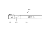
- the GET command M610 includes a header M611, a code M612, and a target property M613.
- the GET command M610 is an example of a second command that requests the state of the PCS 130, and is an example of a command transmitted from the EMS 160 to the PCS 130.
- the header M611 is information indicating the destination of the GET command M610.
- the code M612 is information indicating the type of message including the code M612.
- the code M612 is information indicating that the message including the code M612 is a GET command.
- the target property M613 includes properties that the EMS 160 wants to know. Such properties include, for example, variable properties as with the SET command.
- the variable property includes a set value property indicating the set value of the charge / discharge amount of the storage battery 120, as in the SET command.
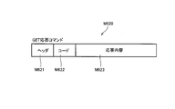
- the GET response command M620 includes a header M621, a code M622, and a response content M623.
- the GET response command M620 is an example of a command transmitted from the PCS 130 to the EMS 160 in response to a command received from the EMS 160.
- the header M621 is information indicating the destination of the GET response command M620.
- the code M622 is information indicating the type of message including the code M622.
- the code M622 is information indicating that the message including the code M622 is a GET response command.
- the response content M623 includes the property requested by the GET command.
- properties include, for example, variable properties, similar to the SET command and GET command.
- the variable property similarly to the SET command and the GET command, there is a set value property indicating a set value of the charge / discharge amount of the storage battery 120.
- the GET response command includes, as a variable property, a specific value that specifies whether or not the GET response command is operating according to the SET command.
- Management method a management method according to the embodiment.
- the predetermined format used in communication between the PCS 130 (communication device 132) and the EMS 160 is a format that conforms to the ECHONET Lite system is illustrated.
- An example in which the SET command and the GET command include a set value property will be described.
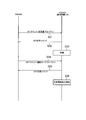
- step S11 the EMS 160 transmits a SET command including the setting value property to the PCS 130.
- step S12 the PCS 130 transmits a SET response command to the EMS 160 in response to the SET command.
- the PCS 130 starts an operation instructed by the SET command.
- the SET command includes the set value property
- the PCS 130 starts the charge / discharge control of the storage battery 120.
- the set value property is a property indicating the charge amount
- the PCS 130 starts charging the storage battery 120.
- the set value property is a property indicating the discharge amount
- the PCS 130 starts discharging the storage battery 120.
- the PCS 130 maintains the variable indicated by the variable property included in the SET command without being changed until the charge / discharge control of the storage battery 120 instructed by the SET command is completed.
- step S14 the EMS 160 transmits a GET command including the setting value property to the PCS 130.
- step S15 the PCS 130 transmits a GET response command to the GET command to the EMS 160.
- the PCS 130 since the variable indicated by the variable property included in the SET command is maintained without being changed, the PCS 130 transmits a GET response command including a copy of the variable indicated by the SET command as the variable property.
- the EMS 160 can recognize that the PCS 130 has received the SET command transmitted in step S11. However, it is difficult for the EMS 160 to determine whether the PCS 130 is actually operating according to the SET command transmitted in step S11.
- step S16 the PCS 130 completes the operation specified by the SET command.
- the PCS 130 completes the charge / discharge control of the storage battery 120. Since the charge / discharge control of the storage battery 120 instructed by the SET command is completed, the PCS 130 may change the variable indicated by the variable property included in the SET command. Here, the PCS 130 transitions from the charge / discharge control state to the standby state in response to the completion of the operation instructed by the SET command.
- step S17 the EMS 160 transmits a GET command including the setting value property to the PCS 130.
- step S18 the PCS 130 transmits a GET response command to the GET command to the EMS 160.
- the PCS 130 transmits a GET response command including a variable property indicating a first specific value indicating that the operation designated by the SET command is completed.
- the first specific value may be different from the value that can be indicated by the variable property included in the SET command.
- the first specific value may be a value associated with the operation completion, or may be zero.
- the operation instructed by the SET command is canceled by the user.
- the operation cancellation may be an event in which the user cancels the operation instructed by the SET command in response to the request from the business operator described above.
- the operation designated by the SET command is interrupted.
- the interruption of the operation may be an event in which the remaining power storage capacity of the storage battery 120 exceeds a predetermined threshold when the set value property is a property indicating the charge amount.
- the interruption of the operation may be an event in which the remaining amount of power stored in the storage battery 120 falls below a threshold when the set value property is a property indicating the discharge amount.
- the interruption of the operation may be a failure or maintenance of one of the storage battery 120 and the PCS 130.
- the interruption of the operation may be a power failure of the power system 10.
- the interruption of the operation may be an event in which the operation designated by the SET command is canceled by the above-described operator.
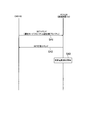
- step S22 the EMS 160 transmits a GET command including the setting value property to the PCS 130.
- the PCS 130 transmits a GET response command for the GET command to the EMS 160.
- the PCS 130 transmits a GET response command including a variable property indicating a second specific value indicating that the operation designated by the SET command has been canceled.
- the second specific value may be different from the value that can be indicated by the variable property included in the SET command.
- the second specific value may be a value associated with the operation cancellation or may be zero.
- the PCS 130 transmits a GET response command including a variable property indicating a third specific value indicating that the operation designated by the SET command is interrupted.
- the third specific value may be different from the value that can be indicated by the variable property included in the SET command.
- the third specific value may be a value associated with the operation interruption or may be zero.
- step S23 the PCS 130 transmits a GET response command for the GET command to the EMS 160, as in FIG.
- the PCS 130 transmits a GET response command including a variable property indicating a third specific value indicating that the operation designated by the SET command is not performed.
- the third specific value may be different from the value that can be indicated by the variable property included in the SET command.
- the third specific value may be a value associated with non-operation, or may be zero.
- the failure of the operation may be an event in which the operation specified by the SET command is restricted by the user.
- the failure of the operation may be an event in which the operation specified by the SET command is restricted by the above-described operator.
- the operation ineffectiveness may be an event in which the operation is not started even after a predetermined time has elapsed since the SET command was received.
- the PCS 130 in the case where the property of the SET command and the GET command includes a variable property indicating a variable that can be changed by the operation of the PCS 130, the PCS 130 is indicated by the variable property until the operation indicated by the SET command is completed. Keep variables unchanged.
- the PCS 130 transmits to the EMS 160 a GET response command including a specific value that specifies whether or not the device is operating according to the SET command as a variable property. Accordingly, the EMS 160 can determine whether the PCS 130 is actually operating according to the SET command based on the specific value included in the GET response command. For example, the EMS 160 can determine whether the operation is completed, the operation is canceled, the operation is interrupted, or the operation is not performed.
- the first command (that is, the SET command) can include an operation mode property indicating the operation mode of the storage battery 120 in addition to the setting value property indicating the setting value of the charge / discharge amount of the storage battery 120. is there.
- the set value property is included in the first command transmitted before the first command including the operation mode property.
- the PCS 130 does not start the charging / discharging of the storage battery 120 and receives the first command including the operation mode property.
- the charging / discharging of the storage battery 120 is controlled based on the operation mode property.
- step S31 the EMS 160 transmits a SET command including a setting value property to the PCS 130.
- step S32 the PCS 130 transmits a SET response command to the EMS 160 in response to the SET command.
- step S33 the PCS 130 receives the SET command including the set value property, but waits without starting the charging / discharging of the storage battery 120.
- step S34 the EMS 160 transmits a SET command including the operation mode property to the PCS 130.
- step S35 the PCS 130 transmits a SET response command to the EMS 160 in response to the SET command.
- step S36 the PCS 130 controls charging / discharging of the storage battery 120 based on the operation mode property.
- the PCS 130 validates the set value property received in step S31 based on the operation mode property. The validation is to charge / discharge the storage battery 120 according to the charge / discharge amount indicated by the set value property.
- the PCS 130 sets the set value property. Can be ignored without enabling.
- the first command (that is, the SET command) can include an operation mode property indicating the operation mode of the storage battery 120 in addition to the setting value property indicating the set value of the charge / discharge amount of the storage battery 120. is there.
- the set value property is included in the first command including the operation mode property.
- step 41 the EMS 160 transmits a SET command including an operation mode property and a set value property to the PCS 130.
- step S42 the PCS 130 transmits a SET response command to the EMS 160 in response to the SET command.
- step S43 the PCS 130 controls charging / discharging of the storage battery 120 based on the operation mode property. Further, the PCS 130 charges / discharges the storage battery 120 according to the charge / discharge amount indicated by the set value property.
- the PCS 130 sets the set value. While ignoring the property, charging / discharging of the storage battery 120 may be controlled based on the operation mode property.
- the predetermined format used in communication between the communication device 132 and the EMS 160 is a format conforming to the ECHONET Lite system.
- the predetermined format may be a format standardized as a format used in the facility 100.
- the response command may be an information notification command including an INF command.
- the PCS 130 may transmit an information notification command including a variable property to the EMS 160 when a predetermined condition is satisfied.
- the case where the predetermined condition is satisfied may be, for example, that the remaining amount of power stored in the storage battery 120 exceeds a predetermined threshold, or may be that the remaining power stored in the storage battery 120 falls below a predetermined threshold.
- the case where the predetermined condition is satisfied may be that the value indicated by the variable property is rewritten by a third party. For example, when a SET command including a variable property is received twice, an INF command including a variable property may be transmitted in response to receiving the second SET command.
- PCS 130 multi-PCS
- PCS 130 may be a PCS that controls the output of storage battery 120.
- the PCS that controls the storage battery 120 is exemplified as the device.
- the device may be a PCS that controls the output of a distributed power source such as a solar cell 110 and a fuel cell.
- the device may be a load 150 such as an air conditioner, a lighting device, a refrigerator, or a television. That is, the property of the first command and the second command may include a variable property indicating a variable that can be changed by the operation of the device regardless of the type of the device.
- the storage battery 120 may be a storage battery provided in the facility 100 or a storage battery provided in an electric vehicle (EV).
- EV electric vehicle
- the communication device 132 constitutes a part of the PCS that controls the storage battery 120, but the embodiment is not limited thereto.
- the communication device 132 may be a remote controller provided separately from the conversion device 131.
- the remote controller may be considered to constitute a part of the PCS that controls the storage battery 120.
- the device managed by the management apparatus (EMS 160) may be a remote controller.
- the first communication unit 132A and the second communication unit 132B have different configurations has been described, but the first communication unit 132A and the second communication unit 132B may be integrated. That is, the first communication unit 132A may also serve as the second communication unit 132B.
Landscapes
- Engineering & Computer Science (AREA)
- Power Engineering (AREA)
- Signal Processing (AREA)
- Computer Networks & Wireless Communication (AREA)
- Remote Monitoring And Control Of Power-Distribution Networks (AREA)
- Supply And Distribution Of Alternating Current (AREA)
- Selective Calling Equipment (AREA)
- Charge And Discharge Circuits For Batteries Or The Like (AREA)
Abstract
Priority Applications (4)
| Application Number | Priority Date | Filing Date | Title |
|---|---|---|---|
| EP17775001.5A EP3439315B1 (fr) | 2016-03-29 | 2017-03-28 | Système de gestion, procédé de gestion, appareil, et dispositif de gestion |
| CN201780021288.2A CN108886644B (zh) | 2016-03-29 | 2017-03-28 | 管理系统、管理方法、设备以及管理装置 |
| US16/089,581 US11056911B2 (en) | 2016-03-29 | 2017-03-28 | Management system, management method, equipment, and management device |
| JP2018508021A JP7122252B2 (ja) | 2016-03-29 | 2017-03-28 | 管理システム、管理方法、機器及び管理装置 |
Applications Claiming Priority (2)
| Application Number | Priority Date | Filing Date | Title |
|---|---|---|---|
| JP2016-066750 | 2016-03-29 | ||
| JP2016066750 | 2016-03-29 |
Publications (1)
| Publication Number | Publication Date |
|---|---|
| WO2017170464A1 true WO2017170464A1 (fr) | 2017-10-05 |
Family
ID=59965642
Family Applications (1)
| Application Number | Title | Priority Date | Filing Date |
|---|---|---|---|
| PCT/JP2017/012503 Ceased WO2017170464A1 (fr) | 2016-03-29 | 2017-03-28 | Système de gestion, procédé de gestion, appareil, et dispositif de gestion |
Country Status (5)
| Country | Link |
|---|---|
| US (1) | US11056911B2 (fr) |
| EP (1) | EP3439315B1 (fr) |
| JP (1) | JP7122252B2 (fr) |
| CN (1) | CN108886644B (fr) |
| WO (1) | WO2017170464A1 (fr) |
Cited By (3)
| Publication number | Priority date | Publication date | Assignee | Title |
|---|---|---|---|---|
| JP2020124022A (ja) * | 2019-01-29 | 2020-08-13 | 京セラ株式会社 | 電力管理装置、蓄電装置及び電力管理方法 |
| JP2022050576A (ja) * | 2019-01-29 | 2022-03-30 | 京セラ株式会社 | 電力管理装置、蓄電装置及び電力管理方法 |
| JP2022191440A (ja) * | 2022-01-11 | 2022-12-27 | 京セラ株式会社 | 電力管理装置、蓄電装置及び電力管理方法 |
Families Citing this family (2)
| Publication number | Priority date | Publication date | Assignee | Title |
|---|---|---|---|---|
| US10978877B2 (en) * | 2016-05-24 | 2021-04-13 | Kyocera Corporation | Management system, management method, power conversion apparatus, and management apparatus |
| CN111314064B (zh) * | 2020-01-20 | 2021-09-17 | 中国银联股份有限公司 | 手机盾状态管理方法、tsm平台服务器及存储介质 |
Citations (3)
| Publication number | Priority date | Publication date | Assignee | Title |
|---|---|---|---|---|
| WO2014103026A1 (fr) * | 2012-12-28 | 2014-07-03 | 日立コンシューマエレクトロニクス株式会社 | Système de commande de puissance, dispositif de commande et procédé de commande de puissance |
| JP2014207585A (ja) * | 2013-04-12 | 2014-10-30 | 京セラ株式会社 | 制御システム、制御装置、情報機器及び制御方法 |
| JP2014216862A (ja) * | 2013-04-25 | 2014-11-17 | 京セラ株式会社 | 制御システム、情報機器及び制御方法 |
Family Cites Families (20)
| Publication number | Priority date | Publication date | Assignee | Title |
|---|---|---|---|---|
| JP2000308272A (ja) * | 1999-04-19 | 2000-11-02 | Yuasa Corp | 蓄電池装置の充電制御装置および充電制御方法ならびに蓄電池装置の充電を制御するためのプログラムを記録したコンピュータ読取可能な記録媒体 |
| JP2001251780A (ja) * | 2000-03-07 | 2001-09-14 | Sharp Corp | 二次電池の充電装置 |
| JP2006209462A (ja) * | 2005-01-28 | 2006-08-10 | Kyocera Corp | 端末装置 |
| US8698604B2 (en) * | 2005-04-25 | 2014-04-15 | Lg Electronics Inc. | Reader control system |
| US8103389B2 (en) * | 2006-05-18 | 2012-01-24 | Gridpoint, Inc. | Modular energy control system |
| US20150276253A1 (en) * | 2008-10-08 | 2015-10-01 | Rey Montalvo | Method and system for fully automated enterprise control of local power usage |
| US9002761B2 (en) * | 2008-10-08 | 2015-04-07 | Rey Montalvo | Method and system for automatically adapting end user power usage |
| JP5270315B2 (ja) | 2008-11-27 | 2013-08-21 | 株式会社日立製作所 | 自動検針方法、自動検針システム、自動検針装置、およびスマートメータ |
| US8975778B2 (en) * | 2009-07-30 | 2015-03-10 | Lutron Electronics Co., Inc. | Load control system providing manual override of an energy savings mode |
| JP5062273B2 (ja) * | 2010-03-12 | 2012-10-31 | ダイキン工業株式会社 | エネルギー管理システム |
| JP5583781B2 (ja) | 2010-10-15 | 2014-09-03 | 三洋電機株式会社 | 電力管理システム |
| US8983669B2 (en) * | 2012-07-31 | 2015-03-17 | Causam Energy, Inc. | System, method, and data packets for messaging for electric power grid elements over a secure internet protocol network |
| US9208676B2 (en) * | 2013-03-14 | 2015-12-08 | Google Inc. | Devices, methods, and associated information processing for security in a smart-sensored home |
| JP5952416B2 (ja) * | 2012-09-27 | 2016-07-13 | 京セラ株式会社 | 管理方法、制御装置及び通信処理デバイス |
| US9912157B2 (en) * | 2013-03-04 | 2018-03-06 | Nec Corporation | Energy management system and energy management method |
| JP6076807B2 (ja) * | 2013-04-09 | 2017-02-08 | 京セラ株式会社 | 情報機器、制御装置、制御システム及び制御方法 |
| JP6339318B2 (ja) * | 2013-04-09 | 2018-06-06 | 京セラ株式会社 | 情報機器、制御システム及び制御方法 |
| JP2015026149A (ja) * | 2013-07-25 | 2015-02-05 | 株式会社日立ソリューションズ | 充電器用課金装置 |
| US10084610B2 (en) * | 2014-01-29 | 2018-09-25 | Kyocera Corporation | Control apparatus and control method |
| WO2018200854A1 (fr) * | 2017-04-27 | 2018-11-01 | Johnson Controls Technology Company | Système d'énergie à commande prédictive pour bâtiment |
-
2017
- 2017-03-28 WO PCT/JP2017/012503 patent/WO2017170464A1/fr not_active Ceased
- 2017-03-28 US US16/089,581 patent/US11056911B2/en active Active
- 2017-03-28 CN CN201780021288.2A patent/CN108886644B/zh active Active
- 2017-03-28 JP JP2018508021A patent/JP7122252B2/ja active Active
- 2017-03-28 EP EP17775001.5A patent/EP3439315B1/fr active Active
Patent Citations (3)
| Publication number | Priority date | Publication date | Assignee | Title |
|---|---|---|---|---|
| WO2014103026A1 (fr) * | 2012-12-28 | 2014-07-03 | 日立コンシューマエレクトロニクス株式会社 | Système de commande de puissance, dispositif de commande et procédé de commande de puissance |
| JP2014207585A (ja) * | 2013-04-12 | 2014-10-30 | 京セラ株式会社 | 制御システム、制御装置、情報機器及び制御方法 |
| JP2014216862A (ja) * | 2013-04-25 | 2014-11-17 | 京セラ株式会社 | 制御システム、情報機器及び制御方法 |
Non-Patent Citations (1)
| Title |
|---|
| See also references of EP3439315A4 * |
Cited By (5)
| Publication number | Priority date | Publication date | Assignee | Title |
|---|---|---|---|---|
| JP2020124022A (ja) * | 2019-01-29 | 2020-08-13 | 京セラ株式会社 | 電力管理装置、蓄電装置及び電力管理方法 |
| JP2022050576A (ja) * | 2019-01-29 | 2022-03-30 | 京セラ株式会社 | 電力管理装置、蓄電装置及び電力管理方法 |
| US12155213B2 (en) | 2019-01-29 | 2024-11-26 | Kyocera Corporation | Energy management apparatus, energy storage apparatus, and energy management method |
| JP2022191440A (ja) * | 2022-01-11 | 2022-12-27 | 京セラ株式会社 | 電力管理装置、蓄電装置及び電力管理方法 |
| JP7316433B2 (ja) | 2022-01-11 | 2023-07-27 | 京セラ株式会社 | 電力管理装置、蓄電装置及び電力管理方法 |
Also Published As
| Publication number | Publication date |
|---|---|
| CN108886644A (zh) | 2018-11-23 |
| CN108886644B (zh) | 2021-05-28 |
| US11056911B2 (en) | 2021-07-06 |
| US20200287408A1 (en) | 2020-09-10 |
| EP3439315B1 (fr) | 2025-01-01 |
| JPWO2017170464A1 (ja) | 2019-03-22 |
| JP7122252B2 (ja) | 2022-08-19 |
| EP3439315A1 (fr) | 2019-02-06 |
| EP3439315A4 (fr) | 2019-08-14 |
Similar Documents
| Publication | Publication Date | Title |
|---|---|---|
| JP6069597B1 (ja) | 電力変換装置、電力管理装置及び電力管理方法 | |
| JP6762360B2 (ja) | 管理システム、管理方法、電力変換装置及び管理装置 | |
| US10840709B2 (en) | Management method, management device, distributed power supply, and management system | |
| JP7122252B2 (ja) | 管理システム、管理方法、機器及び管理装置 | |
| JP6582091B2 (ja) | 電力変換装置、電力管理装置及び電力管理方法 | |
| JP6328216B2 (ja) | 管理システム、管理方法、機器及び管理装置 | |
| JP6366836B2 (ja) | 電力変換装置、電力管理装置及び電力管理方法 | |
| JP6640989B2 (ja) | 管理システム、管理方法、電力変換装置及び管理装置 | |
| JP7643662B2 (ja) | 管理システム、管理方法、表示装置及び管理装置 | |
| JP6085071B1 (ja) | 電力変換装置、電力管理装置及び電力管理方法 | |
| JPWO2017145287A1 (ja) | 管理システム及び管理方法 |
Legal Events
| Date | Code | Title | Description |
|---|---|---|---|
| WWE | Wipo information: entry into national phase |
Ref document number: 2018508021 Country of ref document: JP |
|
| NENP | Non-entry into the national phase |
Ref country code: DE |
|
| WWE | Wipo information: entry into national phase |
Ref document number: 2017775001 Country of ref document: EP |
|
| ENP | Entry into the national phase |
Ref document number: 2017775001 Country of ref document: EP Effective date: 20181029 |
|
| 121 | Ep: the epo has been informed by wipo that ep was designated in this application |
Ref document number: 17775001 Country of ref document: EP Kind code of ref document: A1 |