WO2017170638A1 - Seringue - Google Patents
Seringue Download PDFInfo
- Publication number
- WO2017170638A1 WO2017170638A1 PCT/JP2017/012806 JP2017012806W WO2017170638A1 WO 2017170638 A1 WO2017170638 A1 WO 2017170638A1 JP 2017012806 W JP2017012806 W JP 2017012806W WO 2017170638 A1 WO2017170638 A1 WO 2017170638A1
- Authority
- WO
- WIPO (PCT)
- Prior art keywords
- syringe
- gasket
- pressing
- outer cylinder
- protruding
- Prior art date
- Legal status (The legal status is an assumption and is not a legal conclusion. Google has not performed a legal analysis and makes no representation as to the accuracy of the status listed.)
- Ceased
Links
Images


Classifications
-
- A—HUMAN NECESSITIES
- A61—MEDICAL OR VETERINARY SCIENCE; HYGIENE
- A61M—DEVICES FOR INTRODUCING MEDIA INTO, OR ONTO, THE BODY; DEVICES FOR TRANSDUCING BODY MEDIA OR FOR TAKING MEDIA FROM THE BODY; DEVICES FOR PRODUCING OR ENDING SLEEP OR STUPOR
- A61M5/00—Devices for bringing media into the body in a subcutaneous, intra-vascular or intramuscular way; Accessories therefor, e.g. filling or cleaning devices, arm-rests
- A61M5/178—Syringes
- A61M5/31—Details
Definitions
- the present invention provides a syringe outer cylinder capable of containing a drug, a gasket provided in the syringe outer cylinder so as to be movable in the axial direction, a shaft portion provided with a gasket at a distal end portion, and a proximal end portion of the shaft portion.
- the present invention relates to a syringe provided with a presser having a pressing part that can be pressed by a finger.
- Japanese Patent No. 4738422 discloses a syringe provided with a gasket provided in the syringe outer cylinder so as to be movable in the axial direction and a pusher for pressing the gasket toward the distal end side.
- the pusher includes a shaft portion having a gasket connected to a distal end portion, and a pressing portion that is provided at a proximal end portion of the shaft portion and can be pressed by a finger.
- the gasket is generally made of an elastic material such as rubber, it can be compressed and deformed by further pressing the pressing portion toward the distal end side in a state where the gasket has reached the most advanced position of the movable range. ing. Therefore, the user can move the pressing portion toward the distal end side even after the gasket reaches the most advanced position of the movable range.
- the present invention has been made in view of such problems, and an object of the present invention is to provide a syringe that can easily notify a user by tactile sensation that the entire amount of the medicine has been discharged from the inside of the syringe barrel. To do.
- a syringe according to the present invention is provided with a syringe outer cylinder capable of containing a medicine, an elastic gasket provided in the syringe outer cylinder so as to be movable in an axial direction, A pusher having a shaft portion provided with a contact portion capable of pressing the gasket in a distal direction in contact with the gasket, and a pressing portion provided at a proximal end portion of the shaft portion and capable of being pressed by a finger; and the gasket And an identification unit positioned on the proximal side of the pressing unit so as to come into contact with the finger that operates the pressing unit when reaching the most advanced position of the movable range.
- the identification unit comes into contact with the finger that operates the pressing unit, so that the tactile sensation that the entire amount of the medicine is discharged from the syringe outer cylinder. Can easily inform the user. Thereby, even if it is a case where a gasket is covered with a cover member at the time of use, for example, the user can know easily and reliably that the whole quantity of medicine was discharged from the syringe outer cylinder.
- the identification portion may protrude from the pressing portion to the proximal end in a range of 0.1 mm to 3.0 mm.
- the contact portion can be reliably brought into contact with the finger that operates the pressing portion when the gasket reaches the most advanced position of the movable range.
- the syringe may include a grip attached to a proximal end portion of the syringe outer cylinder and having a finger hook portion, and the identification portion may be a projecting portion projecting from the grip toward the proximal end side.
- the identification unit can be brought into contact with a finger that operates the pressing unit with a simple configuration.
- an insertion hole through which the protruding portion can be inserted may be formed in the pressing portion.
- the protruding portion can be efficiently brought into contact with the finger that operates the pressing portion.
- the protruding portion may be located outside the pressing portion in a direction orthogonal to the axial direction of the shaft portion.
- the protruding portion can be reliably positioned on the proximal end side with respect to the pressing portion.
- the protruding portion may have a shape that follows the outer shape of the pressing portion when the gasket reaches the foremost position of the movable range.
- the protruding portion can be efficiently brought into contact with the finger that operates the pressing portion.
- a plurality of convex portions extending so as to become narrower toward the proximal end side may be formed on the protruding end portion of the protruding portion.
- a set of the identification portions may be provided so as to face each other with the shaft portion interposed therebetween.
- the identification unit can be efficiently brought into contact with the finger that operates the pressing unit.
- the identification part when the gasket reaches the most advanced position of the movable range, the identification part can be brought into contact with the finger that operates the pressing part, so that the entire amount of the medicine is discharged from the syringe outer cylinder. The user can be easily informed by the tactile sensation.
- FIG. 6A is a partially omitted perspective view showing a state of the syringe of FIG. 5 after drug administration
- FIG. 6B is a partially omitted vertical sectional view of FIG. 6A.
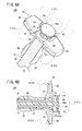
- FIG. 8A is a partially omitted perspective view showing the state of the syringe of FIG. 7 after drug administration
- FIG. 8B is a partially omitted vertical sectional view of FIG. 8A.
- the syringe according to the present invention is configured as a prefilled syringe in which a predetermined medicine is prefilled in a syringe outer cylinder.
- the syringe may suck a predetermined medicine stored in a sealed container such as a vial into a syringe outer cylinder through a needle body and administer the medicine into the living body.
- a sealed container such as a vial into a syringe outer cylinder
- base end the left side of FIG. 2 (needle tip side)
- base end the left side of FIG. 2 (needle tip side)
- base end the left side of FIG. 2 (needle tip side)
- base end the right side (pressing portion side)
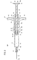
- the syringe 10 ⁇ / b> A includes a needle body 12 that can be punctured on the skin of a living body, a syringe outer cylinder 14 provided at the proximal end of the needle body 12, A gasket 16 provided in the cylinder 14, a pusher 18 provided at the proximal end of the gasket 16, and a detachable grip 20 on the proximal end side of the syringe outer cylinder 14 are provided.
- the needle body 12 is a hollow tubular member having a sharp needle tip 12a at the tip.
- the needle body 12 is made of, for example, a metal material such as stainless steel, aluminum or aluminum alloy, titanium or titanium alloy, or a hard resin material such as polyphenylene sulfide.
- the needle body 12 is protected by a cap (not shown).
- the cap is a hollow member that can accommodate the needle body 12 therein, and is fitted to the distal end side of the syringe outer cylinder 14 in a state where the portion from the needle tip 12a to the syringe outer cylinder 14 in the needle body 12 is covered. Configured to be compatible.
- This cap is attached to the syringe outer cylinder 14 so that the needle body 12 is not exposed before the syringe 10A is used.
- the needle body 12 can be exposed by detaching from the syringe outer cylinder 14 by pulling the cap toward the distal end side.
- the syringe outer cylinder 14 is integrally formed of a resin material or glass. It is preferable that the syringe outer cylinder 14 has transparency so that the position of the gasket 16 therein can be visually recognized.
- the syringe outer cylinder 14 is provided at a needle hub 22 that holds the proximal end side of the needle body 12, an outer cylinder main body 24 provided at the proximal end portion of the needle hub 22, and a proximal end portion of the outer cylinder main body 24. And a flange 26.
- the needle hub 22 has a needle insertion hole 28 into which the proximal end side of the needle body 12 is inserted.
- the proximal end side of the needle body 12 is fixed to the wall surface constituting the needle insertion hole 28.
- Examples of the method for fixing the needle body 12 include insert molding, high-frequency or laser thermal welding, and adhesion using an adhesive.
- the outer cylinder main body 24 is a cylindrical member extending in the axial direction of the needle body 12, and is configured to be able to accommodate a medicine therein.
- An inner end face 14a is provided at the distal end portion of the outer cylinder main body 24 so as to be directed toward the base end side of the outer cylinder main body 24 and can contact the gasket 16 (see FIGS. 2 and 4).
- the inner end surface 14 a extends so as to incline in the radial direction of the outer cylinder main body 24 from the tip of the inner peripheral surface of the outer cylinder main body 24 toward the tip side.
- the base end of the outer cylinder main body 24 is opened so that the pusher 18 can be inserted.
- the flange 26 is an annular member that extends radially outward from the proximal end portion of the outer cylinder main body 24.
- the gasket 16 for example, natural rubber, butyl rubber, isoprene rubber, butadiene rubber, styrene-butadiene rubber, various rubber materials such as silicone rubber, polyurethane-based, polyester-based, polyamide-based, olefin-based, styrene-based, etc. And various elastic materials such as thermoplastic elastomers or mixtures thereof.
- the gasket 16 is provided so as to be movable in a liquid-tight manner along the axial direction of the syringe outer cylinder 14. That is, the gasket 16 is slidable with respect to the inner peripheral surface of the outer cylinder main body 24.
- the gasket 16 is provided with a distal end surface 16a capable of contacting the inner end surface 14a of the syringe outer cylinder 14 (see FIGS. 2 and 4).
- the distal end surface 16a is inclined radially inward toward the distal end side.
- a screw hole 30 is formed in the proximal end surface of the gasket 16.
- the pusher 18 is made of a resin material, and includes a shaft portion 32 inserted into the syringe outer cylinder 14 and a pressing portion provided at a proximal end portion of the shaft portion 32. 34.
- a screw portion 36 that is screwed into the screw hole 30 of the gasket 16 is formed at the tip of the shaft portion 32 (see FIG. 2).
- a plurality (three) of pusher flanges 38a to 38c are provided on the distal end side of the shaft portion 32 so as to be separated from each other in the axial direction.
- the pusher flange 38a located on the most distal side among the plurality of pusher flanges 38a to 38c is in contact with the proximal end of the gasket 16 and functions as a contact portion that presses the gasket 16 together with the screw portion 36 in the distal direction.
- the screw portion 36 may be omitted from the shaft portion 32.
- the pusher flange 38a located on the most distal side functions as a contact portion, and the gasket 16 can be moved only in the distal direction.
- the pressing portion 34 is a disk-shaped member formed in a size that can be pressed by the user's finger F, and extends radially outward from the proximal end portion of the shaft portion 32.
- a plurality of (four in the example of FIG. 1) insertion holes 40 are formed in the pressing portion 34.
- the plurality of insertion holes 40 are provided at equal intervals in the circumferential direction of the pressing portion 34.
- Each insertion hole 40 has a shape in which the center side of the sector shape is cut out in an arc shape in plan view.
- the grip 20 is for the user to put his / her finger F when pushing the pusher 18 into the distal end side of the syringe outer cylinder 14, and is configured to be detachable from the proximal end side of the syringe outer cylinder 14.
- the grip 20 is made of a resin material. However, the grip 20 can be made of any material other than the resin material.
- the grip 20 includes a fixing portion 42 provided on the proximal end side of the outer cylinder main body 24 and a finger hooking portion 44 provided on the proximal end portion of the fixing portion 42.
- the fixed portion 42 extends in an arc shape along the outer peripheral surface on the proximal end side of the outer cylinder main body 24.
- the first cutout portion 46 that can receive the outer cylinder main body 24 is formed in the fixing portion 42 over the entire length thereof.
- the finger-hanging portion 44 has a pair of extending portions 48 and 50 that extend from the base end of the fixing portion 42 so as to be separated from each other in the radial direction.
- the finger hook portion 44 is formed with a flange groove 52 into which the flange 26 can be fitted.
- a second notch portion 54 that can receive the shaft portion 32 is formed at the proximal end portion of the finger hanging portion 44 located on the proximal end side with respect to the flange 26.
- the first notch 46, the flange groove 52, and the second notch 54 communicate with each other.
- the width dimension of the second notch 54 is smaller than the width dimension of the first notch 46.
- a plurality of (two in the example of FIG. 1) protrusions (identification parts) 56 protruding in the base end side (in the direction opposite to the gasket 16) are provided on the base end face of the finger hanging part 44. These projecting portions 56 face each other with the shaft portion 32 interposed therebetween. The spacing between the protruding portions 56 is smaller than the outer diameter of the pressing portion 34.
- Each protrusion 56 is configured to be able to be inserted through an insertion hole 40 formed in the pressing portion 34.
- each protruding portion 56 is a protruding end of the protruding portion 56 in a state where the gasket 16 has reached the foremost position of the movable range (a state where the front end surface 16a of the gasket 16 is in contact with the inner end surface 14a of the syringe outer cylinder 14). It is comprised so that a part may be located in the base end side rather than the base end surface 34a of the press part 34 (refer FIG.3 and FIG.4).
- the protruding length L1 of the protruding portion 56 with respect to the base end surface 34a of the pressing portion 34 is set to a length capable of giving a tactile sensation to the finger F operating the pressing portion 34.
- the protrusion length L1 is preferably set to 0.1 mm or more and 1.5 mm or less, and more preferably set to 0.2 mm or more and 1.0 mm or less.
- the pressing portion 34 can be surely pushed forward to the tip side until the gasket 16 reaches the most advanced position of the movable range, and the protruding portion 56 can be reliably pressed against the finger F operating the pressing portion 34. Because.
- the protrusion length L1 can be arbitrarily set.
- the protruding end surface of each protruding portion 56 is curved in a convex shape. Thereby, moderate tactile sensation can be given to the finger F that operates the pressing portion 34.
- the syringe 10A according to the present embodiment is basically configured as described above. Next, a method of using the syringe 10A will be described.
- a cap (not shown) is detached from the syringe outer cylinder 14 to expose the distal end side of the needle body 12.
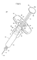
- the user holds the syringe 10 ⁇ / b> A in a state where a plurality of fingers F are hung on the finger hook 44 and the pusher 18.
- the user brings the thumb F1 of the right hand into contact with the base end surface 34a of the pressing portion 34, the index finger F2 of the right hand is hung on one extension portion 48, and the middle finger of the right hand F3 is hung on the other extension part 50.
- the user punctures the skin of the living body 12 and presses the pressing portion 34 toward the distal end side with the thumb F1. Then, since the pusher 18 pressed by the thumb F1 moves to the distal end side in the syringe outer cylinder 14, the medicine filled in the syringe outer cylinder 14 is pressed by the gasket 16 and passes through the lumen of the needle body 12. To be administered in vivo.
- each protruding portion 56 passes through the insertion hole 40 of the pressing portion 34 and protrudes to the proximal end side from the proximal end surface 34 a of the pressing portion 34. F1 is pressed to the base end side by the protruding end surface of the protruding portion 56.
- a cover member (not shown) that covers the needle body 12 so as not to be exposed before use and moves the needle body 12 to the proximal end side of the syringe outer cylinder 14 during use to expose the needle body 12 may be provided.
- the gasket 16 may be covered with a cover member when the syringe 10A is used.
- the protruding portion 56 contacts the finger F (thumb F1) that operates the pressing portion 34. Therefore, even when the gasket 16 is covered with the cover member during use, the user can easily and reliably know that the entire amount of the medicine has been discharged from the syringe outer cylinder 14.
- the protruding portions 56 can be efficiently brought into contact with the thumb F1 that operates the pressing portion 34. Moreover, since one set is provided so that the protrusions 56 face each other with the shaft part 32 interposed therebetween, the protrusions 56 can be more efficiently brought into contact with the thumb F ⁇ b> 1 that operates the pressing part 34.
- the syringe 10A according to the present embodiment is not limited to the configuration described above.
- One or three or more protrusions 56 may be provided.
- One, two, three, or five or more insertion holes 40 may be provided.
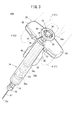
- the syringe 10 ⁇ / b> B according to the present embodiment is different from the syringe 10 ⁇ / b> A according to the first embodiment described above in the configuration of the pusher 60, the grip 62, and the protruding portion (identification portion) 64.
- the pusher 60 includes a shaft portion 32 and a disk-like pressing portion 66 in which the insertion hole 40 described above is not formed.
- the grip 62 includes a fixed portion 42 and a finger hook portion 68.
- the finger hanging portion 68 is formed with a second notch portion 70 that can receive the shaft portion 32.
- the width dimension of the second notch 70 is set to be substantially the same as the width dimension of the first notch 46.
- each protruding portion 64 is positioned outside the pressing portion 66 in a direction orthogonal to the axial direction of the shaft portion 32.
- each protruding portion 64 has a protruding end portion of the protruding portion 64 that is more than the proximal end surface 66a of the pressing portion 66 when the gasket 16 reaches the most advanced position of the movable range (in the state of FIGS. 6A and 6B). It has a shape that protrudes toward the proximal end and that follows the outer shape of the pressing portion 66. In FIG.
- the protrusion length L2 of the protrusion 64 with respect to the base end surface 66a of the pressing part 66 is set to be the same as or slightly longer than the protrusion length L1 described above.
- the protrusion length L2 is preferably set to 0.5 mm or more and 3.0 mm or less.
- the protruding end surface of each protruding portion 64 is curved in a convex shape.
- each protruding portion 64 is based on the outer side in the radial direction of the pressing portion 66 than the base end surface 66 a of the pressing portion 66. Projects to the end side. Since each protrusion part 64 has the shape which follows the external shape of the press part 66 at this time, the protrusion end surface can be made to contact a user's thumb F1 reliably and efficiently.
- the tactile sensation can be given to the thumb F ⁇ b> 1 that operates the pressing portion 66 by the protruding portion 64, the user can easily know from the tactile sensation that the entire amount of the medicine has been discharged from the syringe outer cylinder 14.
- the syringe 10B according to the present embodiment is not limited to the configuration described above.
- One or three or more protruding portions 64 may be provided.
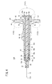
- each protruding portion 72 is different from the protruding portion 64 described above only in that the protruding portion 72 extends in the circumferential direction of the pressing portion 66 and the protruding end portion is different in shape.
- each convex part 74 is formed in a substantially triangular shape.
- the protruding end surface of each convex portion 74 may be curved.
- tip of the convex part 74) L3 with respect to the base end surface 66a of the press part 66 is set similarly to the protrusion length L1 mentioned above.
- Such a syringe 10 ⁇ / b> C can achieve the same effects as the syringe 10 ⁇ / b> B described above. Moreover, since the some convex part 74 is formed in the protrusion edge part of each protrusion part 72, the comparatively strong tactile sensation can be given to the thumb F1 which operates the press part 66 by the protrusion part 72. FIG.
- the syringe 10C according to the present embodiment is not limited to the configuration described above.
- One or three or more protrusions 72 may be provided.
- each syringe 10A to 10C may not include the needle body 12 and the needle hub 22. That is, the needle hub 22 having the needle body 12 may be detachable from the syringe outer cylinder 14.
- the syringe according to the present invention is not limited to the above-described embodiment, and various configurations can be adopted without departing from the gist of the present invention.
Landscapes
- Health & Medical Sciences (AREA)
- Vascular Medicine (AREA)
- Engineering & Computer Science (AREA)
- Anesthesiology (AREA)
- Biomedical Technology (AREA)
- Heart & Thoracic Surgery (AREA)
- Hematology (AREA)
- Life Sciences & Earth Sciences (AREA)
- Animal Behavior & Ethology (AREA)
- General Health & Medical Sciences (AREA)
- Public Health (AREA)
- Veterinary Medicine (AREA)
- Infusion, Injection, And Reservoir Apparatuses (AREA)
Abstract
Une seringue (10A) comprend un cylindre externe (14) pouvant recevoir un médicament; un joint d'étanchéité élastique (16); un piston (18) pourvu d'une partie tige (32) dotée d'un rebord de piston (38a) pouvant venir en contact avec le joint d'étanchéité (16) au niveau d'une partie d'extrémité distale de celui-ci et comprimer le joint d'étanchéité (16) dans une direction de l'extrémité distale, et une partie de pression (34) sur laquelle un doigt peut exercer une pression, la partie de pression (34) se situant vers une partie d'extrémité proximale; et une partie en saillie (56) positionnée davantage vers l'extrémité proximale que vers la partie de pression (34) de façon à pouvoir venir en contact avec le doigt (F) actionnant la partie de pression (34) lorsque le joint d'étanchéité (16) atteint une position la plus distale dans sa plage mobile.
Applications Claiming Priority (2)
| Application Number | Priority Date | Filing Date | Title |
|---|---|---|---|
| JP2016-067828 | 2016-03-30 | ||
| JP2016067828 | 2016-03-30 |
Publications (1)
| Publication Number | Publication Date |
|---|---|
| WO2017170638A1 true WO2017170638A1 (fr) | 2017-10-05 |
Family
ID=59964750
Family Applications (1)
| Application Number | Title | Priority Date | Filing Date |
|---|---|---|---|
| PCT/JP2017/012806 Ceased WO2017170638A1 (fr) | 2016-03-30 | 2017-03-29 | Seringue |
Country Status (1)
| Country | Link |
|---|---|
| WO (1) | WO2017170638A1 (fr) |
Citations (3)
| Publication number | Priority date | Publication date | Assignee | Title |
|---|---|---|---|---|
| JP2002052081A (ja) * | 2000-07-31 | 2002-02-19 | Becton Dickinson & Co | 選択的に格納可能な針を有する皮下注射器 |
| US20100076378A1 (en) * | 2007-03-21 | 2010-03-25 | Midland Medical Devices Holdings, Llc | Safety Medical Syringe with Retractable Needle and Including a Plunger that is Received within a Barrel |
| WO2015151692A1 (fr) * | 2014-03-31 | 2015-10-08 | テルモ株式会社 | Seringue |
-
2017
- 2017-03-29 WO PCT/JP2017/012806 patent/WO2017170638A1/fr not_active Ceased
Patent Citations (3)
| Publication number | Priority date | Publication date | Assignee | Title |
|---|---|---|---|---|
| JP2002052081A (ja) * | 2000-07-31 | 2002-02-19 | Becton Dickinson & Co | 選択的に格納可能な針を有する皮下注射器 |
| US20100076378A1 (en) * | 2007-03-21 | 2010-03-25 | Midland Medical Devices Holdings, Llc | Safety Medical Syringe with Retractable Needle and Including a Plunger that is Received within a Barrel |
| WO2015151692A1 (fr) * | 2014-03-31 | 2015-10-08 | テルモ株式会社 | Seringue |
Similar Documents
| Publication | Publication Date | Title |
|---|---|---|
| US11878154B2 (en) | Needle shield puller for drug delivery system | |
| JP6342815B2 (ja) | 液体投与具 | |
| CA2932976C (fr) | Dispositif a usage unique pour la distribution de medicaments en cartouche | |
| CN102665801B (zh) | 药物输送装置 | |
| US8162883B2 (en) | Puncture needle assembly and medicinal liquid injector | |
| JP6499158B2 (ja) | プレフィルドシリンジ | |
| WO2015001819A1 (fr) | Outil d'administration de liquide | |
| KR20180091078A (ko) | 의료용 주입기용 캡 | |
| JP2012254353A (ja) | 初期吸引を容易にするために弾性部を有する注射器 | |
| KR20180093023A (ko) | 의료용 주입기용 반구형 부분을 구비한 캡 | |
| CN104487115A (zh) | 液体投放器具 | |
| JP6914913B2 (ja) | 薬液投与器具、薬液投与器具の使用方法及び薬液投与器具の製造方法 | |
| JP2020099832A (ja) | 医療インジェクタおよびキャップリムーバ | |
| WO2017170638A1 (fr) | Seringue | |
| JP7183248B2 (ja) | 皮内針及びその包装体並びに注射装置 | |
| JP2015031784A (ja) | 疑似体験デバイス | |
| WO2017170500A1 (fr) | Ensemble d'élément de préhension et de seringue | |
| WO2018037221A1 (fr) | Dispositif protecteur | |
| WO2014013547A1 (fr) | Instrument pour administration de liquide | |
| KR20180016745A (ko) | 주사기용 니들유닛 | |
| JP2015081964A (ja) | 疑似体験デバイス |
Legal Events
| Date | Code | Title | Description |
|---|---|---|---|
| NENP | Non-entry into the national phase |
Ref country code: DE |
|
| 121 | Ep: the epo has been informed by wipo that ep was designated in this application |
Ref document number: 17775175 Country of ref document: EP Kind code of ref document: A1 |
|
| 122 | Ep: pct application non-entry in european phase |
Ref document number: 17775175 Country of ref document: EP Kind code of ref document: A1 |
|
| NENP | Non-entry into the national phase |
Ref country code: JP |