WO2017170692A1 - Système et procédé de gestion de tranche - Google Patents
Système et procédé de gestion de tranche Download PDFInfo
- Publication number
- WO2017170692A1 WO2017170692A1 PCT/JP2017/012891 JP2017012891W WO2017170692A1 WO 2017170692 A1 WO2017170692 A1 WO 2017170692A1 JP 2017012891 W JP2017012891 W JP 2017012891W WO 2017170692 A1 WO2017170692 A1 WO 2017170692A1
- Authority
- WO
- WIPO (PCT)
- Prior art keywords
- slice
- area
- terminal
- management system
- information
- Prior art date
- Legal status (The legal status is an assumption and is not a legal conclusion. Google has not performed a legal analysis and makes no representation as to the accuracy of the status listed.)
- Ceased
Links
Images



Classifications
-
- H—ELECTRICITY
- H04—ELECTRIC COMMUNICATION TECHNIQUE
- H04W—WIRELESS COMMUNICATION NETWORKS
- H04W36/00—Hand-off or reselection arrangements
- H04W36/24—Reselection being triggered by specific parameters
- H04W36/32—Reselection being triggered by specific parameters by location or mobility data, e.g. speed data
- H04W36/326—Reselection being triggered by specific parameters by location or mobility data, e.g. speed data by proximity to another entity
Definitions
- the present invention relates to a slice management system and a slice management method.
- a network system using a conventional virtualization technology is a virtual network that is logically generated on a network infrastructure by virtually separating hardware resources using the virtualization technology disclosed in Non-Patent Document 1. Create a slice. Then, by assigning a service to the slice, it is possible to provide the service using a network of independent slices. Thereby, when a slice is assigned to each service having various requirements, it becomes easy to satisfy the requirements of each service, and the signaling processing and the like can be reduced.
- a terminal that receives a service provided by the slice connects to a slice connectable in the area for each area.
- the slice connected to the movement source area by the terminal is not generated in the movement destination area. There is. In this case, the terminal cannot continue to connect in the destination area to the slice to which the terminal was connected in the source area. As a result, the terminal cannot receive the service provided in the movement source area in the movement destination area.
- the present invention has been made in view of such problems, and provides a slice management system and a slice management method that can provide a slice that can be continuously connected even when a terminal moves across an area. With the goal.
- a slice management system is a slice management system that manages a slice that is a virtual network generated on a network infrastructure, and relates to a slice to which a terminal can be connected for each area.
- the slice management system includes a memory for storing slice information, and the slice management system refers to the memory to connect to the slice connected in the source area in the destination area where the terminal moves across the area. If it is determined whether or not connection is possible, the slice is generated in the movement destination area so that the terminal can connect to the slice in the movement destination area.
- the slice is generated in the destination area. The terminal can continue to connect to the slice in the destination area. That is, it is possible to provide a slice that can be continuously connected even when the terminal moves in the area.
- the terminal when the terminal requests connection to the slice in the movement destination area, the terminal connects to the slice connected in the movement source area in the movement destination area. It is good also as determining whether it can do. If such a configuration is adopted, it is determined whether or not the terminal can connect to the slice connected in the source area in the destination area when the terminal requests connection to the slice in the destination area. If it is determined that connection is not possible, the slice is generated in the movement destination area. Thereby, even when the terminal moves across the area, it is possible to more reliably provide a slice that can be continuously connected.
- the one area is set as a movement source area and the area adjacent to the one area is set as a movement destination area. Then, it may be determined whether or not it is possible to connect to the slice connected in the movement source area. If such a configuration is adopted, it is determined whether or not the terminal can be connected to a slice connected in the one area in the adjacent area when the terminal moves to one area, and it is determined that the terminal cannot be connected. In this case, the slice is generated in the adjacent area. Accordingly, it is possible to provide a slice that can be continuously connected even when the terminal moves from one area to an adjacent area of the one area. That is, since the slice can be generated in the area before the terminal moves to the next area, it is possible to provide a slice that can be continuously connected more reliably.
- the terminal is triggered by the fact that the terminal is predicted to move across the area based on at least one of the position information, speed information, and acceleration information of the terminal.
- the area where the current position is located may be the movement source area and the area where movement is predicted to be the movement destination area. In the movement destination area, it may be determined whether or not the slice connected to the movement source area can be connected. .
- the area where movement is predicted triggered by the fact that the terminal is predicted to move across the area based on at least one of the position information, speed information and acceleration information of the terminal, It is determined whether or not it is possible to connect to a slice connected in the area where it is currently located.
- the slice is generated in an area where movement is predicted. Accordingly, it is possible to provide a slice that can be continuously connected even when the terminal moves from an area where the terminal is currently located to an area where movement is predicted. That is, since a slice can be generated in advance in the area before the terminal actually moves to the area where movement is predicted next, it is possible to provide a slice that can be continuously connected more reliably.
- the slice information stored in the memory includes the number of terminals connected to the slice for each area, and the slice management system stores the slice information stored in the memory.
- the generated slice may be deleted based on the number of terminals included in.
- the slice management system when a slice is generated in the movement destination area, it is generated only when it is determined that the slice can be generated based on the network infrastructure resource status of the movement destination area. It is good to do. By adopting such a configuration, the slice can be expanded more reliably.
- one aspect of the present invention can be described as an invention of a slice management method as described below, in addition to the invention of a slice management system as described above.
- This is substantially the same invention only in different categories, and has the same operations and effects.
- the slice management method is a slice management method executed by a slice management system that manages a slice that is a virtual network generated on a network infrastructure, and a terminal can be connected to each area.
- a slice management system that manages a slice that is a virtual network generated on a network infrastructure, and a terminal can be connected to each area.
- the memory storing slice information related to a slice, it is determined whether or not the terminal can connect to the slice connected in the source area in the destination area where the terminal moves across the area.
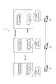
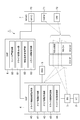
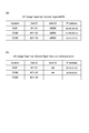
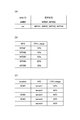
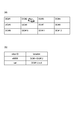
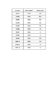
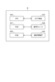
- FIG. 1 is a system configuration diagram of a slice management system according to an embodiment of the present invention. It is a figure which shows the example of a table of the slice information stored in memory (DNS). It is a figure which shows the example of a table of the resource amount stored in memory (NFVO, VNFM, VIM). It is a figure explaining extension of a slice when a terminal moves. It is a figure which shows the example of a table of the terminal number information stored in the memory (SMF).
- FIG. 1 is a diagram for explaining slice connection when a terminal moves between areas in the prior art.
- DC # 1, DC # 2, and DC # 3, which are three DCs (Data Centers), are provided at locations geographically different from each other.
- Each DC forms a slice that spans between DCs using the network infrastructure included in the DC.
- a slice (or network slice) is a virtual network or a service network that is logically generated on a network infrastructure by virtually separating link and node resources of a network device and combining the separated resources. They separate resources and do not interfere with each other.
- the service refers to a service using network resources such as a communication service (private line service or the like) or an application service (service using a moving image distribution or sensor device such as an embedded device).
- DC # 1 and DC # 2 form an NS (Network Slice) -Car which is a slice straddling DC # 1 and DC # 2.
- NS-Car includes NFE (Network Function Entity) -Car, which is a functional entity of a slice, generated in each DC as a component.
- NFE Network Function Entity
- NS-Car provides a mobile communication service between vehicles to a terminal (car). As a service requirement in NS-Car, low delay and local communication are required.
- DC # 1, DC # 2, and DC # 3 form an NS-eMBB (evolved Mobile Broad Band) that is a slice straddling DC # 1, DC # 2, and DC # 3.
- NS-eMBB includes NFE-eMBB, which is a functional entity of a slice, generated in each DC as a constituent element.
- NS-eMBB has the same role as an existing mobile phone communication network, and provides a mobile communication service that enables a terminal to connect to the Internet.
- a delay and a bandwidth at the level of an existing mobile phone communication network are required.
- a mobile communication service provision range (a range in which a terminal can perform wireless communication) provided by a slice formed by a network infrastructure included in each DC is referred to as an area.
- DC may be referred to as an area.
- DC # 1 and DC # 2 are urban areas
- DC # 3 is a local area.
- NS-Car is formed (covered) in the DC # 1 and DC # 2 urban areas, but is not formed (covered) in the DC # 3 local area.
- NS-eMBB is generally formed in DC # 1 and DC # 2 urban areas and DC # 3 local areas.
- a car 2a which is a terminal that can access a mobile communication service provided by NS-Car, sequentially goes to a DC # 1 urban area, a DC # 2 urban area, and a DC # 3 local area.
- a scene of moving between areas is shown.
- the car 2a is connected to the NS-Car in the DC # 1 city area, and after moving to the DC # 2 city area, the car 2a continues to connect to the NS-Car (in the DC # 2 city area). be able to.
- the NS-Car cannot be connected to the NS-Car because the NS-Car is not formed in the DC # 3 local area.
- the vehicle 2a that has moved to the DC # 3 local area cannot continue to connect to the NS-Car connected in the DC # 1 and DC # 2 urban areas.
- FIG. 2 is a diagram for explaining slice connection when a terminal moves between areas in the slice management system 1. The description of the same contents as in FIG. 1 is omitted.
- the slice management system 1 determines whether the car 2a can continue to connect to the NS-Car connected in the DC # 2 city area, If it is determined that the connection cannot be established, the NS-Car is expanded (generated / formed) by forming the NS-Car in the DC # 3 so that the car 2a can continue to connect to the NS-Car.
- the slice management system 1 can extend NS-Car to DC # 3 in advance before the car 2a moves to the local area of DC # 3. As described above, in the slice management system 1, by extending NS-Car, the car 2a that has moved to the DC # 3 local area is connected to the NS # DC and DC # 2 urban areas. -You can continue to connect to Car.
- FIG. 3 is a system configuration diagram of the slice management system 1.
- the slice management system 1 (slice management system) includes UE (User Equipment) 2 (terminal), BS (Base Station) 3, SSF (Slice Selection Function) 4, DNS (Domain Name System) 5 ( Memory), SMF (Service-slice Mapping Function) 6 and MANO (Management And Orchestration) 7.
- UE User Equipment
- BS Base Station
- SSF Slice Selection Function
- DNS Domain Name System
- SMF Service-slice Mapping Function
- MANO Management And Orchestration
- the slice management system 1 provides a communication function to the UE 2 that is a mobile communication terminal by a virtual server that operates in a virtual machine realized on a physical server. That is, the slice management system 1 is a virtualized mobile communication network.
- the communication function is provided to the mobile communication terminal by executing a communication process corresponding to the communication function by the virtual machine.
- the slice management system 1 includes, or may include, components defined in 4G (4th generation mobile communication standard), 5G (5th generation mobile communication standard), NFV (Network Functions Virtualisation) architecture, etc. Details of these components will be omitted as appropriate.
- the UE 2 is a mobile communication terminal capable of performing mobile communication by connecting to a mobile communication network provided by the slice management system 1.
- UE2 is a car provided with a mobile communication function.
- the UE 2 connects to the slice managed (formed) by the slice management system 1 by receiving a slice connection request, which is information for requesting connection to the slice, and receives a service provided by the slice. be able to.
- the UE 2 sends “UE Usage Type” as a parameter for specifying which service the slice management system 1 is requested to receive, that is, which slice is requested to be connected to.
- "And" Service Type "are included in the slice connection request and sent.
- UE Usage Type is information indicating “which service is to be executed” defined for each UE 2 or each user of UE 2. Specific examples of “UE Usage Type” include “mobile phone” indicating a mobile phone and a car “car” (connected to a network).
- Service Type is information defined independently of “UE Usage Type”, and is information describing which service is to be executed. Specific examples of “Service Type” include “voice call” indicating voice communication service, “movie streaming” indicating video streaming service, “eMBB” indicating eMBB service, and “intra car communication” indicating inter-vehicle communication service. Is mentioned.
- the UE 2 may include, in addition to “UE Usage Type” and “Service Type”, terminal identification information for identifying the UE 2 and cell identification information for identifying the cell of the BS 3 in which the UE 2 is located in the slice connection request. . Note that, when the UE 2 moves across areas (when moving between areas), the UE 2 transmits a slice connection request (to the BS 3 in the movement destination area) in the movement destination area.
- BS3 is a general base station.
- BS3 receives the slice connection request from UE2, BS3 transmits the received slice connection request to SSF4.
- the BS 3 may transmit the cell connection information including the cell identification information for identifying the cell in the BS 3 where the UE 2 that transmitted the slice connection request is located.
- the BS 3 receives, as a response to the transmission of the slice connection request to the SSF 4, the slice connection destination information regarding the slice to be connected to the UE 2 or the connection destination error information indicating that the connection destination slice has not been determined.
- the BS 3 connects the UE 2 that has transmitted the slice connection request to the slice indicated by the received slice connection destination information.
- the BS 3 receives the connection destination error information from the SSF 4
- the BS 3 transmits the received connection destination error information to the UE 2. Note that the UE 2 determines that it cannot connect to the slice by receiving the connection destination error information.
- the SSF 4 is an independent node (such as a server device).
- the SSF 4 determines to which slice the UE 2 that has transmitted the slice connection request is connected based on the received slice connection request, and when the connection destination slice is determined, Slice connection destination information regarding the connection destination slice is transmitted to BS3.
- connection destination error information indicating that fact is transmitted to the BS 3. Details of the SSF 4 (functional blocks shown in FIG. 3) will be described later.
- the DNS 5 is a node that provides a general DNS service.
- the DNS 5 is a slice managed by the slice management system 1 and stores slice information related to a slice to which the UE 2 can be connected for each area.
- the slice information includes DC identification information for identifying a DC to which the slice is provided, cell identification information for identifying a cell in the DC to which the slice is provided, slice identification information for identifying the slice, and an IP address of the slice.
- the slice information may be associated with each “UE Usage Type” and “Service Type”.
- FIG. 4 is a diagram showing a table example of slice information stored in the DNS 5.
- “UE Usage Type” is “car” and “Service Type” is associated with “eMBB”, and the slice indicated by the slice information indicates that the car is eMBB. Indicates that the slice is for executing a service.
- a slice with slice identification information “eMBB” is formed in cells # 1 to 10 of DC # 1, and the IP address is “aa. aa.aa.aa ”.
- “UE Usage Type” is “car” and “Service Type” is associated with “intra car communication”, and the slice information indicated by the slice information is shown. Indicates that the vehicle is a slice for executing the e-vehicle communication service. Note that the third record in the table example shown in FIG. 4B indicates that no slice is formed (provided) for the car to execute the inter-vehicle communication service in cells # 11 to 30 of DC # 3. ing.
- the SMF 6 is a node that manages slices and makes decisions in the SSF 4 based on service request conditions, slice resource usage, and the like. Details of the SMF 6 (functional blocks shown in FIG. 3) will be described later.
- MANO7 is an architecture for managing resources related to slices. As shown in FIG. 3, MANO 7 is configured to include NFVO 70, VNFM 71, and VIM 72.
- the NFVO 70 is a node that manages the VNFM 71 and the VIM 72 and performs creation / extension / deletion of a slice and acquisition of a resource operation status in accordance with an instruction from the SMF 6.
- the VNFM 71 is a node that performs resource management of software resources of slices in the DC.
- the VIM 72 is a node that performs resource management of physical / logical hardware resources of slices in the DC.
- the NFVO 70 when the NFVO 70 receives a slice creation instruction, which is information for instructing the creation of a slice, from the SMF 6, the NFVO 70 causes the VNFM 71 and the VIM 72 to acquire resources on the corresponding DC, and the NFE for slices on the DC And create a slice. Further, for example, when the NFVO 70 receives a slice extension instruction, which is information indicating the extension of a slice, from the SMF 6, the NFVO 70 causes the VNFM 71 and the VIM 72 to acquire the corresponding resources on the DC, and uses the slice extension instructions on the DC. Configure NFE and expand slice.
- the NFE for the corresponding slice on the DC is deleted from the VNFM 71 and VIM 72, the resources on the DC are released, and the slice is deleted. delete.
- the NFE configured on the DC may be configured separately for U-plane and C-plane.
- FIG. 5 is a diagram showing a table example of resource amounts stored in each of the NFVO 70, the VNFM 71, and the VIM 72.
- FIG. 5A is an example of a table of resource amounts stored in the NFVO 70.
- slice identification information is associated with identification information (NFE identification information) of the constituent elements of the slice indicated by the slice identification information.
- FIG. 5B is a table example of resource amounts stored in the VNFM 71.
- the identification information of the NFE that is a component of the slice is associated with the CPU usage rate of the NFE.
- FIG. 5C is an example of a table of resource amounts stored in the VIM 72.
- DC identification information for identifying a DC, hardware identification information existing in the DC, and a CPU usage rate of the hardware are associated with each other.
- the SMF 6 transmits a resource operation status acquisition instruction, which is information for instructing acquisition of the resource operation status, to each of the NFVO 70, VNFM 71, and VIM 72, and as a response to each of the NFVO 70, VNFM 71, and VIM 72, A table of stored resource amounts is acquired and stored in the SMF 6.
- the SMF 6 periodically transmits a resource operation status acquisition instruction to store the latest resource amounts of the NFVO 70, the VNFM 71, and the VIM 72 in the SMF 6, and based on the stored latest resource amount, the slice is identified as a specific DC. It is determined whether or not construction is possible.
- any one or more of BS3, SSF4, DNS5, SMF6, NFVO70, VNFM71 and VIM72 included in the slice management system 1 described above may be realized by a physical server device or the like as described above. It may be realized by executing a program on a typical server device. Also, any two or more of BS3, SSF4, DNS5, SMF6, NFVO70, VNFM71, and VIM72 may be realized by one physical server device or the like, or a program on one physical server device May be realized by executing.
- the SSF 4 may be configured by an MME (Mobility Management Entity), an HSS (Home Subscriber Server), and a DNS in a 3GPP (Third Generation Partnership Project) architecture.
- the slice connection request acquisition unit 40 receives (acquires) the slice connection request from the UE 2 via the BS 3 and transmits the received slice connection request to the slice connection determination unit 43.
- the area movement detection unit 41 detects that the UE 2 has moved to one area (move from an area different from the one area to the one area). For example, the area movement detection unit 41 makes an inquiry to the HSS (not shown) using the terminal identification information included in the slice connection request as an argument, and obtains the history information of the area information of the UE 2 managed by the HSS and the position information of each area. It acquires and detects that UE2 moved to one area based on the acquired information. When the area movement detection unit 41 detects that the UE 2 has moved to one area, the area movement detection unit 41 transmits the detection result to the slice connection determination unit 43.
- the area movement prediction unit 42 predicts that the UE 2 moves between areas based on at least one of position information, speed information, and acceleration information of the UE 2. For example, the area movement prediction unit 42 periodically acquires at least one of the position information, speed information, and acceleration information of the UE 2 from the BS 3 and uses the terminal identification information included in the slice connection request as an argument to the HSS (not shown). An inquiry is made, the history of the location information of the UE 2 managed by the HSS and the location information of each area are acquired, and the UE 2 is predicted to move between the areas based on the acquired information. When the area movement prediction unit 42 predicts that the UE 2 moves between areas, the area movement prediction unit 42 transmits a prediction result to the slice connection determination unit 43.
- the slice connection determination unit 43 determines whether or not the UE 2 can connect to the slice connected in the movement source area when the UE 2 moves between the areas. Judgment.
- the slice connection determination unit 43 triggers the determination when the slice connection request is received from the slice connection request acquisition unit 40, or when the detection result is received from the area movement detection unit 41, or the area This is performed when the prediction result is received from the movement prediction unit 42.
- the slice connection determination unit 43 triggers the determination when the slice connection request is received from the slice connection request acquisition unit 40, or when the detection result is received from the area movement detection unit 41, or the area This is performed when the prediction result is received from the movement prediction unit 42.
- the slice connection determination unit 43 When the slice connection determination unit 43, which is the first opportunity, receives a slice connection request from the slice connection request acquisition unit 40, the slice connection determination unit 43 indicates UE2 indicated by the terminal identification information included in the received slice connection request. UE2 moves between areas by comparing the “UE Usage Type”, “Service Type” and cell identification information included in the previously received slice connection request from the same content included in the slice connection request received this time. And whether or not it is trying to connect to the same slice as the previous time. Note that the SSF 4 stores a history of past slice connection requests in order to compare with the previously received slice connection request.
- the slice connection determination unit 43 displays “UE Usage” included in the slice connection request received this time.
- the UE 2 makes an inquiry about the IP address of the slice to which the UE 2 is requesting connection.
- the slice information table stored in DNS 5 is the table shown in FIG. 4, where “UE Usage Type” included in the slice connection request is “car” and “Service Type” is “eMBB”. If the cell identification information is “# 22”, it corresponds to the third record in the table shown in FIG. 4A, and the slice connection determination unit 43 receives the IP address “cc.cc” as the DNS response from the DNS 5. .cc.cc ”is received. In this way, when the IP address of the slice for which UE2 is requesting connection can be acquired, the slice connection determination unit 43 determines the slice to which UE2 was connected in the source area when UE2 moves between areas. It is determined that connection is possible in the destination area. Subsequently, the slice connection determination unit 43 returns the acquired IP address to the BS 3 and connects the UE 2 to the slice indicated by the IP address.
- the slice connection determination unit 43 receives information indicating that there is no slice that can be connected as a DNS response from the DNS 5. In this way, when there is no slice to which the UE 2 is requesting connection, the slice connection determining unit 43 sets the slice to which the UE 2 was connected in the movement source area when the UE 2 moves between the areas in the movement destination area. Determine that connection is not possible. When it is determined that connection is not possible, the slice connection determination unit 43 transmits the “UE Usage Type”, “Service Type”, and cell identification information included in the received slice connection request to the slice extension request unit 44.
- the slice connection determination unit 43 When the slice connection determination unit 43, which is the second opportunity, receives the detection result from the area movement detection unit 41, the slice connection determination unit 43 sets the one area where the movement is detected as the movement source area and the one area. Is determined as a movement destination area, and it is determined whether or not the target UE 2 can connect to a slice connected in the movement source area in the movement destination area.
- the SMF 6 stores in advance the example tables shown in FIGS. 6 (a) and 6 (b).
- FIG. 6A is an example of a table showing the adjacent relationship (positional relationship) of each area. For example, when the movement source area (one area) is DC # 2, the slice connection determination unit 43 makes an inquiry to the SMF 6 and acquires the table example illustrated in FIG.
- FIG. 6B is a table example showing in which area the slice managed by the slice management system 1 exists. For example, when the identification information of the slice to which the UE 2 is connected in DC # 2 that is the movement source area is “car”, the slice connection determination unit 43 obtains the identification information by an inquiry to the HSS (not shown). ), DC # 1, DC # 5 and DC # 1 among DC # 1, DC # 3, DC # 5, DC # 6 and DC # 7 which are destination areas based on the table example shown in FIG.
- the slice connection determination unit 43 transmits, to the slice extension request unit 44, the identification information of the area determined to be unable to be connected and the identification information of the slice to which the UE 2 is connected in the movement source area.
- the slice connection determination unit 43 When the slice connection determination unit 43, which is the third opportunity, receives the prediction result from the area movement prediction unit 42, the slice connection determination unit 43 predicts the movement source area and the movement in the area where the target UE 2 is currently located.
- the determined area is set as a movement destination area, and it is determined whether or not the terminal can connect to the slice connected in the movement source area.
- the determination method is the same as in the case of the second opportunity described above.
- the slice connection determination unit 43 transmits, to the slice extension request unit 44, the identification information of the area determined to be unable to be connected and the identification information of the slice to which the UE 2 is connected in the movement source area.
- the slice extension request unit 44 receives the “UE Usage Type”, “Service Type” and cell identification information received from the slice connection determination unit 43, or area identification information and slice identification information, and based on the received information. Then, a slice expansion request for expanding (generating / forming) a slice corresponding to the corresponding cell or area is transmitted to the SMF 6.
- the slice extension request unit 44 may include the information received from the slice connection determination unit 43 in the slice extension request. Based on the transmission of the slice extension request by the slice extension request unit 44, the SMF 6 and MANO 7 extend the slice to the destination area so that the UE 2 can connect to the slice in the destination area.
- the resource amount confirmation unit 60 When receiving the slice extension request from the slice extension request unit 44 of the SSF 4, the resource amount confirmation unit 60 extends the slice indicated by the slice extension request in the cell or area indicated by the slice extension request. Check if necessary resources can be secured. For example, as described above, the resource amount confirmation unit 60 confirms whether the reservation is possible based on the resource amount table stored in the SMF 6. Note that the resource amount confirmation unit 60 may confirm the NFE necessary for expanding the slice. When the resource amount confirmation unit 60 confirms that the resource amount can be secured, the resource amount confirmation unit 60 transmits the received slice expansion request to the slice expansion instruction unit 61. On the other hand, when the resource amount confirmation unit 60 confirms that the slice cannot be secured, that is, when it is determined that the slice cannot be expanded, it transmits error information indicating that the slice cannot be expanded to the SSF 4.
- the slice extension instruction unit 61 transmits a slice extension instruction to the MANO 7 (or NFVO 70) to instruct the extension of the slice based on the information included in the received slice extension request. That is, the slice extension instruction unit 61 transmits a slice extension instruction for instructing extension of the slice only when it is determined that the slice can be extended based on the network infrastructure resource status of the movement destination area.
- the slice expansion process in MANO 7 is the same as the process according to the prior art, and thus the description thereof is omitted. With the expansion (generation / formation) of the slice by MANO7, the table of resource amounts stored in each of NFVO70, VNFM71, and VIM72 shown in FIG. 5 is updated, and slice information of DNS5 is also updated. Note that MANO 7 may cause the newly generated slice to belong to another slice instead of the extension by causing the NFE generated for slice extension to belong to another slice.
- the slice expansion instruction unit 61 receives slice expansion completion information indicating that the slice expansion is completed from MANO 7 (or NFVO 70).
- the slice extension completion information includes information on the extended slice.
- the slice extension instruction unit 61 that has received the slice extension completion information transmits information on the extended slice included in the received slice extension completion information to the SSF 4.
- the SSF 4 that has received the information makes a DNS inquiry to the slice information of the DNS 5 (updated) based on the received information, acquires the IP address of the extended slice, and the IP address is obtained from the BS 3.
- the UE 2 is instructed to connect to the indicated slice.
- the connected terminal number management unit 62 stores (manages) slice information including the number of terminals connected to the slice for each area.
- FIG. 7 is a diagram illustrating an example of a table of slice information stored in the SMF 6.
- the table example shown in FIG. 7 is a table for a specific slice, area identification information for identifying an area (“location” column), and information on whether or not the slice exists in the area (“slice exist?”). “Column” and the number of UEs 2 connected to the slice in the area (“active user” column). Note that the above slice information may be included in the DNS 5.
- the slice deletion instruction unit 63 deletes the expanded slice based on the number of UEs 2 connected to the slice for each area included in the slice information stored by the connected terminal number management unit 62. For example, the slice deletion instruction unit 63 deletes a slice in an area where the number of connected UEs 2 is zero in the table example illustrated in FIG. The slice deletion instruction unit 63 may delete slices in an area where the number of connected UEs 2 is a predetermined number or less. Further, in the table example shown in FIG. 7, the table further includes information indicating whether or not the slice in the area is expanded by the slice management system 1. Only the extended slice may be deleted with reference to the information. When the above slice information is included in the DNS 5, the slice deletion instruction unit 63 inquires the DNS 5 to acquire the slice information.
- the SSF 4 is composed of hardware such as a CPU.
- FIG. 8 is a diagram illustrating an example of a hardware configuration of the SSF 4.
- the SSF 4 shown in FIG. 3 physically includes one or a plurality of CPUs 400, a RAM 401 and a ROM 402 as main storage devices, an input / output device 403 such as a display, a communication module 404, and an auxiliary storage device. 405 and the like are configured as a computer system.
- the functions of the functional blocks of the SSF 4 shown in FIG. 3 are the same as those of the input / output device 403 and the communication module under the control of the CPU 400 by reading predetermined computer software on the hardware such as the CPU 400 and the RAM 401 shown in FIG. This is realized by operating 404 and the auxiliary storage device 405 and reading and writing data in the RAM 401.
- FIG. 9 is a diagram illustrating an example of a hardware configuration of the SMF 6.
- the SMF 6 shown in FIG. 3 physically includes one or a plurality of CPUs 600, a main memory RAM 601 and ROM 602, an input / output device 603 such as a display, a communication module 604, and an auxiliary storage device.
- the computer system includes 605 and the like.
- the functions of the functional blocks of the SMF 6 shown in FIG. 3 are the same as those shown in FIG. 9 by loading predetermined computer software on the hardware such as the CPU 600 and the RAM 601, thereby controlling the input / output device 603 and the communication module. This is realized by operating 604 and the auxiliary storage device 605 and reading and writing data in the RAM 601.
- a processor such as CPU 400 or CPU 600
- all or a part of the function is executed by constructing a dedicated integrated circuit (IC).
- IC integrated circuit
- the above functions may be executed by constructing a dedicated integrated circuit for performing image processing and communication control.
- software, instructions, etc. may be transmitted / received via a transmission medium.
- software may use websites, servers, or other devices using wired technology such as coaxial cable, fiber optic cable, twisted pair and digital subscriber line (DSL) and / or wireless technology such as infrared, wireless and microwave.
- wired technology such as coaxial cable, fiber optic cable, twisted pair and digital subscriber line (DSL) and / or wireless technology such as infrared, wireless and microwave.
- DSL digital subscriber line
- wireless technology such as infrared, wireless and microwave.
- a slice connection request is acquired by the slice connection request acquisition unit 40 of the SSF 4 (step S1).
- the slice connection determination unit 43 makes a DNS inquiry to the DNS 5 (step S2), and a DNS response is acquired as a response (step S3).
- the slice connection determination unit 43 determines whether or not the UE 2 can connect to the slice connected in the movement source area in the movement destination area (determination). Step) Here, it is determined that it cannot be connected to the slice (step S4).
- the SSF 4 confirms whether to connect to another slice, such as referring to a priority list stored in the SSF 4 in which the connection destinations of the slices are arranged in order of priority (step S5).
- the slice expansion request unit 44 transmits a slice expansion request to the SMF 6 (step S6).
- step S7 it is confirmed by the resource amount confirmation unit 60 of the SMF 6 whether or not the resources necessary for expanding the slice can be secured (step S7). It is assumed that it can be secured here.
- the resource amount confirmation unit 60 confirms the NFE necessary for expanding the slice (step S8).
- the slice extension instruction unit 61 transmits a slice extension instruction to the MANO 7 (step S9).
- slice expansion is performed by MANO 7 (step S10, generation step), and slice expansion completion information is transmitted to SMF 6 (step S11).
- step S12 table updates of NFVO 70, VNFM 71, and VIM 72 are performed (step S12), and DNS 5 is updated (step S13), and the information of the extended slice is reflected in each.
- the information of the extended slice is notified to the SSF 4 by the slice extension instruction unit 61 (step S14).
- the DNS expansion request unit 44 of the SSF 4 makes a DNS inquiry to the DNS 5 (step S15), and a DNS response is acquired as a response (step S16), whereby the IP address of the expanded slice is obtained. To be acquired.
- the slice expansion request unit 44 instructs the BS 3 to select a slice based on the acquired IP address (step S17).
- the slice management system 1 of the present embodiment when the UE 2 moves between areas, even if the UE 2 cannot connect to the slice connected in the movement source area in the movement destination area, the slice is moved to the movement destination area. UE2 can continue to connect to the slice in the destination area. That is, it is possible to provide a slice that can be continuously connected even when the UE 2 moves between areas.
- the UE 2 when the UE 2 moves between areas, the UE 2 connects in the source area when triggered by the connection request to the slice in the source area. It is determined whether or not the slice that has been connected can be connected in the movement destination area. If it is determined that the slice cannot be connected, the slice is expanded to the movement destination area. Thereby, even when UE2 moves between areas, the slice which can be connected continuously can be provided more reliably.
- the slice management system 1 of the present embodiment it is determined whether or not the UE 2 can connect to the slice connected in the one area in the adjacent area when the UE 2 moves to the one area. If it is determined that connection is not possible, the slice is expanded to the adjacent area. Accordingly, it is possible to provide a slice that can be continuously connected even when the UE 2 moves from one area to an adjacent area of the one area. That is, before UE2 moves to the next area, the slice can be extended to the area in advance, so that it is possible to provide a slice that can be continuously connected more reliably.
- the UE 2 is triggered by the fact that the UE 2 is predicted to move between areas based on at least one of the position information, the speed information, and the acceleration information of the UE 2. It is determined whether or not it is possible to connect to the slice that is connected to the connected slice in the area where it is currently located. If it is determined that the slice cannot be connected, the slice is expanded to the area that is predicted to move. The Accordingly, it is possible to provide a slice that can be continuously connected even when the UE 2 moves from an area where the UE 2 is currently located to an area where movement is predicted. That is, since the slice can be extended to the area before UE2 actually moves to the next predicted movement area, it is possible to provide a more connectable slice.
- the slice management system 1 of the present embodiment for example, by deleting a slice in which the number of connected UEs 2 is zero, network resources for maintaining the slice can be saved.
- the slice management system 1 of the present embodiment when a slice is extended to a movement destination area, only when it is determined that the slice can be extended based on the network infrastructure resource status of the movement destination area. Since it is expanded, the slice can be expanded more reliably.
- the phrase “based on” does not mean “based only on”, unless expressly specified otherwise. In other words, the phrase “based on” means both “based only on” and “based at least on.”
- notification of predetermined information is not limited to explicitly performed, but is performed implicitly (for example, notification of the predetermined information is not performed). Also good.
- a device includes a single device and a plurality of such devices.
- SYMBOLS 1 ... Slice management system, 2 ... UE, 3 ... BS, 4 ... SSF, 5 ... DNS, 6 ... SMF, 7 ... MANO, 40 ... Slice connection request acquisition part, 41 ... Area movement detection part, 42 ... Area movement prediction , 43 ... Slice connection determination part, 44 ... Slice extension request part, 60 ... Resource amount confirmation part, 61 ... Slice extension instruction part, 62 ... Connected terminal number management part, 63 ... Slice deletion instruction part, 70 ... NFVO, 71 ... VNFM, 72 ... VIM.
Landscapes
- Engineering & Computer Science (AREA)
- Computer Networks & Wireless Communication (AREA)
- Signal Processing (AREA)
- Mobile Radio Communication Systems (AREA)
- Data Exchanges In Wide-Area Networks (AREA)
Abstract
La présente invention concerne un système de gestion de tranche (1) qui gère des tranches qui constituent des réseaux virtuels générés sur une infrastructure de réseau, et qui est composé d'un DNS (5) destiné à stocker, sur une base zone par zone, des informations de tranches concernant des tranches auxquelles un UE (2) peut être connecté. En réponse à l'UE (2) faisant une demande de connexion de tranche dans une zone de destination de mouvement dans laquelle l'UE (2) s'est déplacé à travers une autre zone, le système de gestion de tranche (1), par référence au DNS (5), détermine si une connexion peut être établie dans la zone de destination de mouvement vers une tranche vers laquelle une connexion a été établie dans une zone d'origine de mouvement. S'il est déterminé que la connexion ne peut pas être établie, le système de gestion de tranche (1) génère la tranche dans la zone de destination de mouvement de telle façon que l'UE (2) peut se connecter à la tranche dans la zone de destination de mouvement.
Priority Applications (3)
| Application Number | Priority Date | Filing Date | Title |
|---|---|---|---|
| JP2018509339A JPWO2017170692A1 (ja) | 2016-04-01 | 2017-03-29 | スライス管理システム及びスライス管理方法 |
| EP17775226.8A EP3439250A4 (fr) | 2016-04-01 | 2017-03-29 | Système et procédé de gestion de tranche |
| US16/085,056 US20190059036A1 (en) | 2016-04-01 | 2017-03-29 | Slice management system and slice management method |
Applications Claiming Priority (2)
| Application Number | Priority Date | Filing Date | Title |
|---|---|---|---|
| JP2016074607 | 2016-04-01 | ||
| JP2016-074607 | 2016-04-01 |
Publications (1)
| Publication Number | Publication Date |
|---|---|
| WO2017170692A1 true WO2017170692A1 (fr) | 2017-10-05 |
Family
ID=59964602
Family Applications (1)
| Application Number | Title | Priority Date | Filing Date |
|---|---|---|---|
| PCT/JP2017/012891 Ceased WO2017170692A1 (fr) | 2016-04-01 | 2017-03-29 | Système et procédé de gestion de tranche |
Country Status (4)
| Country | Link |
|---|---|
| US (1) | US20190059036A1 (fr) |
| EP (1) | EP3439250A4 (fr) |
| JP (1) | JPWO2017170692A1 (fr) |
| WO (1) | WO2017170692A1 (fr) |
Cited By (4)
| Publication number | Priority date | Publication date | Assignee | Title |
|---|---|---|---|---|
| JP2020025210A (ja) * | 2018-08-08 | 2020-02-13 | 株式会社Nttドコモ | リソース割当装置およびリソース割当方法 |
| WO2020032145A1 (fr) * | 2018-08-09 | 2020-02-13 | 日本電信電話株式会社 | Système et procédé de communication |
| CN114979721A (zh) * | 2022-05-18 | 2022-08-30 | 咪咕文化科技有限公司 | 视频切片方法、装置、设备及存储介质 |
| JP7383190B1 (ja) | 2023-03-30 | 2023-11-17 | Kddi株式会社 | 情報処理装置及び情報処理方法 |
Families Citing this family (1)
| Publication number | Priority date | Publication date | Assignee | Title |
|---|---|---|---|---|
| CN112671547B (zh) * | 2019-10-15 | 2022-12-27 | 华为技术有限公司 | 车内业务切片的资源配置方法及装置、系统 |
Family Cites Families (4)
| Publication number | Priority date | Publication date | Assignee | Title |
|---|---|---|---|---|
| EP2901766A2 (fr) * | 2012-09-27 | 2015-08-05 | Interdigital Patent Holdings, Inc. | Architecture de bout en bout, structure d'api, découverte et accès dans un réseau virtualisé |
| JP6218166B2 (ja) * | 2013-03-04 | 2017-10-25 | 国立研究開発法人情報通信研究機構 | 基地局間ハンドオーバ方法 |
| US9775045B2 (en) * | 2015-09-11 | 2017-09-26 | Intel IP Corporation | Slicing architecture for wireless communication |
| US10645528B2 (en) * | 2015-09-18 | 2020-05-05 | Huawei Technologies Co., Ltd. | System and methods for reliable communication with mobility along a predictable route |
-
2017
- 2017-03-29 WO PCT/JP2017/012891 patent/WO2017170692A1/fr not_active Ceased
- 2017-03-29 US US16/085,056 patent/US20190059036A1/en not_active Abandoned
- 2017-03-29 EP EP17775226.8A patent/EP3439250A4/fr not_active Withdrawn
- 2017-03-29 JP JP2018509339A patent/JPWO2017170692A1/ja active Pending
Non-Patent Citations (4)
| Title |
|---|
| "Feasibility Study on New Services and Markets Technology Enablers", 3GPP TR 22.891 V14.0.0, March 2016 (2016-03-01), XP051088163 * |
| NAKAUCHI, KIYOHIDE ET AL.: "Bring your own network: Design and implementation of a virtualized wifi network", CONSUMER COMMUNICATIONS AND NETWORKING CONFERENCE (CCNC), 10 January 2014 (2014-01-10), pages 483 - 488, XP032626056 * |
| See also references of EP3439250A4 * |
| ZHANG, HANG ET AL.: "5G wireless network: MyNET and SONAC", IEEE NETWORK, vol. 29, no. 4, 2015, pages 14 - 23, XP011664255 * |
Cited By (8)
| Publication number | Priority date | Publication date | Assignee | Title |
|---|---|---|---|---|
| JP2020025210A (ja) * | 2018-08-08 | 2020-02-13 | 株式会社Nttドコモ | リソース割当装置およびリソース割当方法 |
| WO2020032145A1 (fr) * | 2018-08-09 | 2020-02-13 | 日本電信電話株式会社 | Système et procédé de communication |
| JP2020027989A (ja) * | 2018-08-09 | 2020-02-20 | 日本電信電話株式会社 | 通信システムおよび通信方法 |
| JP7091924B2 (ja) | 2018-08-09 | 2022-06-28 | 日本電信電話株式会社 | 通信システムおよび通信方法 |
| CN114979721A (zh) * | 2022-05-18 | 2022-08-30 | 咪咕文化科技有限公司 | 视频切片方法、装置、设备及存储介质 |
| CN114979721B (zh) * | 2022-05-18 | 2024-02-23 | 咪咕文化科技有限公司 | 视频切片方法、装置、设备及存储介质 |
| JP7383190B1 (ja) | 2023-03-30 | 2023-11-17 | Kddi株式会社 | 情報処理装置及び情報処理方法 |
| JP2024143291A (ja) * | 2023-03-30 | 2024-10-11 | Kddi株式会社 | 情報処理装置及び情報処理方法 |
Also Published As
| Publication number | Publication date |
|---|---|
| JPWO2017170692A1 (ja) | 2019-02-07 |
| EP3439250A1 (fr) | 2019-02-06 |
| EP3439250A4 (fr) | 2019-10-30 |
| US20190059036A1 (en) | 2019-02-21 |
Similar Documents
| Publication | Publication Date | Title |
|---|---|---|
| JP6867371B2 (ja) | スライス管理システム及びスライス管理方法 | |
| JP7684336B2 (ja) | サービス加入方法、プログラム、チップ、情報伝達装置、ネットワーク装置、ネットワーク機能ネットワーク要素、及び、通信システム | |
| KR102138002B1 (ko) | 세션 관리 기능 엔티티 선택 방법, 장치, 및 시스템 | |
| US12063559B2 (en) | Method and apparatus for complementary and equivalent network slice deployment in a network environment | |
| JP6402253B2 (ja) | 通信制御方法、通信制御装置、及び通信システム | |
| US20220225321A1 (en) | Dynamic Hierarchical Reserved Resource Allocation | |
| JP6941613B2 (ja) | スライス管理システムおよびスライス管理方法 | |
| WO2017170692A1 (fr) | Système et procédé de gestion de tranche | |
| KR20190077510A (ko) | 부하 마이그레이션 방법, 장치 및 시스템 | |
| JP6236714B2 (ja) | オフロード処理方法、制御ユニット、およびシステム | |
| US20200022195A1 (en) | Association Management Method And Network Node | |
| EP4094486B1 (fr) | Procédé et appareil de service informatique périphérique | |
| CN109155939B (zh) | 一种负载迁移方法、装置及系统 | |
| US20230078344A1 (en) | Switching control method and apparatus for service server, electronic device, and storage medium | |
| EP3364694B1 (fr) | Procédé de sélection d'élément de réseau, et sélecteur d'élément de réseau | |
| CN118201018A (zh) | 地理智能网络功能请求路由 | |
| JP7065905B2 (ja) | サービスネットワークを選択するための方法およびネットワークデバイスならびに管理デバイス | |
| WO2023185710A1 (fr) | Procédé de détermination de scénario de transfert de contexte d'application et appareil de communication | |
| KR101522523B1 (ko) | 근거리 무선망 접속을 위한 장치, 이를 위한 방법 및 이 방법이 기록된 컴퓨터 판독 가능한 기록매체 | |
| RU2783811C2 (ru) | Способ подписки на услуги и устройство | |
| US11606672B2 (en) | Information transmission method, network element selector, and controller | |
| CN117528556A (zh) | 数据网关的选择方法及信令网关 | |
| CN117041860A (zh) | 一种漫游场景下的通信方法及装置 | |
| CN121240152A (zh) | 信息传输方法及通信装置 | |
| JP2017157949A (ja) | 在圏情報管理方法および通信システム |
Legal Events
| Date | Code | Title | Description |
|---|---|---|---|
| ENP | Entry into the national phase |
Ref document number: 2018509339 Country of ref document: JP Kind code of ref document: A |
|
| 121 | Ep: the epo has been informed by wipo that ep was designated in this application |
Ref document number: 17775226 Country of ref document: EP Kind code of ref document: A1 |
|
| NENP | Non-entry into the national phase |
Ref country code: DE |