WO2017170814A1 - Terminal utilisateur, station de base sans fil et procédé de communication sans fil - Google Patents
Terminal utilisateur, station de base sans fil et procédé de communication sans fil Download PDFInfo
- Publication number
- WO2017170814A1 WO2017170814A1 PCT/JP2017/013136 JP2017013136W WO2017170814A1 WO 2017170814 A1 WO2017170814 A1 WO 2017170814A1 JP 2017013136 W JP2017013136 W JP 2017013136W WO 2017170814 A1 WO2017170814 A1 WO 2017170814A1
- Authority
- WO
- WIPO (PCT)
- Prior art keywords
- transmission
- uci
- pucch
- information
- signal
- Prior art date
- Legal status (The legal status is an assumption and is not a legal conclusion. Google has not performed a legal analysis and makes no representation as to the accuracy of the status listed.)
- Ceased
Links
Images








Classifications
-
- H—ELECTRICITY
- H04—ELECTRIC COMMUNICATION TECHNIQUE
- H04W—WIRELESS COMMUNICATION NETWORKS
- H04W8/00—Network data management
- H04W8/22—Processing or transfer of terminal data, e.g. status or physical capabilities
-
- H—ELECTRICITY
- H04—ELECTRIC COMMUNICATION TECHNIQUE
- H04W—WIRELESS COMMUNICATION NETWORKS
- H04W16/00—Network planning, e.g. coverage or traffic planning tools; Network deployment, e.g. resource partitioning or cells structures
- H04W16/14—Spectrum sharing arrangements between different networks
-
- H—ELECTRICITY
- H04—ELECTRIC COMMUNICATION TECHNIQUE
- H04W—WIRELESS COMMUNICATION NETWORKS
- H04W72/00—Local resource management
- H04W72/04—Wireless resource allocation
- H04W72/044—Wireless resource allocation based on the type of the allocated resource
- H04W72/0446—Resources in time domain, e.g. slots or frames
-
- H—ELECTRICITY
- H04—ELECTRIC COMMUNICATION TECHNIQUE
- H04W—WIRELESS COMMUNICATION NETWORKS
- H04W72/00—Local resource management
- H04W72/04—Wireless resource allocation
- H04W72/044—Wireless resource allocation based on the type of the allocated resource
- H04W72/0453—Resources in frequency domain, e.g. a carrier in FDMA
-
- H—ELECTRICITY
- H04—ELECTRIC COMMUNICATION TECHNIQUE
- H04W—WIRELESS COMMUNICATION NETWORKS
- H04W72/00—Local resource management
- H04W72/20—Control channels or signalling for resource management
- H04W72/21—Control channels or signalling for resource management in the uplink direction of a wireless link, i.e. towards the network
-
- H—ELECTRICITY
- H04—ELECTRIC COMMUNICATION TECHNIQUE
- H04W—WIRELESS COMMUNICATION NETWORKS
- H04W72/00—Local resource management
- H04W72/20—Control channels or signalling for resource management
- H04W72/23—Control channels or signalling for resource management in the downlink direction of a wireless link, i.e. towards a terminal
-
- H—ELECTRICITY
- H04—ELECTRIC COMMUNICATION TECHNIQUE
- H04W—WIRELESS COMMUNICATION NETWORKS
- H04W74/00—Wireless channel access
- H04W74/08—Non-scheduled access, e.g. ALOHA
- H04W74/0808—Non-scheduled access, e.g. ALOHA using carrier sensing, e.g. carrier sense multiple access [CSMA]
-
- H—ELECTRICITY
- H04—ELECTRIC COMMUNICATION TECHNIQUE
- H04W—WIRELESS COMMUNICATION NETWORKS
- H04W74/00—Wireless channel access
- H04W74/002—Transmission of channel access control information
- H04W74/006—Transmission of channel access control information in the downlink, i.e. towards the terminal
Definitions
- the present invention relates to a user terminal, a radio base station, and a radio communication method in a next-generation mobile communication system.
- LTE Long Term Evolution
- LTE-A also referred to as LTE Advanced, LTE Rel. 10, 11 or 12
- LTE Long Term Evolution
- Successor systems for example, FRA (Future Radio Access), 5G (5th generation mobile communication system), LTE Rel. 13 or later
- FRA Full Radio Access
- 5G 5th generation mobile communication system
- LTE Rel. 13 or later are also being studied.
- LTE of 8-12 the specification has been performed on the assumption that exclusive operation is performed in a frequency band (also referred to as a licensed band) licensed by a telecommunications carrier (operator).
- a frequency band also referred to as a licensed band
- the license band for example, 800 MHz, 1.7 GHz, 2 GHz, and the like are used.
- UE User Equipment
- Rel. 13 In LTE it is considered to expand the frequency of the LTE system using an unlicensed spectrum band (also referred to as an unlicensed band) that can be used in addition to the license band.
- an unlicensed spectrum band also referred to as an unlicensed band
- Non-patent document 2 As the unlicensed band, for example, the use of a 2.4 GHz band or a 5 GHz band that can use Wi-Fi (registered trademark) or Bluetooth (registered trademark) is being studied.
- LAA License-Assisted Access
- DC Dual Connectivity
- SA unlicensed band stand-alone
- LBT Listen Before Talk
- CCA Carrier Channel Assessment
- uplink control information (UCI) in an unlicensed band cell is being studied.
- the availability of transmission changes depending on the result of the LBT in the cell of the unlicensed band, unless the UCI transmission operation in the cell of the unlicensed band is properly defined, the UCI is not transmitted at a desired timing. Communication throughput and / or communication quality may be reduced.
- the present invention has been made in view of the above points, and provides a user terminal, a radio base station, and a radio communication method capable of suitably realizing UCI transmission at a desired timing in a carrier in which an LBT is set. This is one of the purposes.
- a user terminal includes a transmission unit that transmits a signal on a carrier that performs listening before uplink transmission, and whether at least one of the carriers is a cell that transmits a PUCCH (Physical Uplink Control Channel).
- a receiving unit that receives PUCCH cell setting information related to this, and a control unit that controls transmission of uplink control information (UCI) in the carrier based on the PUCCH cell setting information.
- UCI uplink control information
- UCI transmission at a desired timing can be suitably realized on a carrier in which LBT is set.
- LTE / LTE-A in an unlicensed band
- an interference control function is required for coexistence with LTE, Wi-Fi, or other systems of other operators.
- a system that operates LTE / LTE-A in an unlicensed band is generally referred to as LAA, LAA-LTE, LTE-U, U-, regardless of whether the operation mode is CA, DC, or SA. It may be called LTE or the like.
- a transmission point for example, a radio base station (eNB), a user terminal (UE), etc.
- eNB radio base station
- UE user terminal
- an unlicensed band carrier which may be called an unlicensed cell, unlicensed CC, etc.
- another entity for example, another UE communicating with the carrier of the unlicensed band is detected, transmission using the carrier is prohibited.
- the transmission point performs listening (LBT) at a timing before a predetermined period before the transmission timing.
- the transmission point for executing LBT is the timing of a predetermined period before the transmission timing (for example, the immediately preceding subframe), and the entire target carrier band (for example, one component carrier (CC)) )
- the entire target carrier band for example, one component carrier (CC)
- CC component carrier
- listening means that a certain transmission point (for example, a radio base station, a user terminal, etc.) exceeds a predetermined level (for example, predetermined power) from another transmission point before transmitting a signal.
- a predetermined level for example, predetermined power
- the listening performed by the radio base station and / or the user terminal may be referred to as LBT, CCA, carrier sense, or the like.
- LBT performed before downlink transmission by the eNB may be referred to as DL LBT
- LBT performed before uplink transmission by the UE may be referred to as UL LBT.
- the UE may be notified of information on a carrier on which UL LBT is to be performed, and may determine the carrier based on the information and perform UL LBT.
- the transmission point When the transmission point can confirm that no other device is communicating, the transmission point performs transmission using the carrier. For example, when the reception power measured by the LBT (reception signal power during the LBT period) is equal to or less than a predetermined threshold, the transmission point determines that the channel is in a free state (LBT free ) and performs transmission.
- LBT free a free state
- the channel is in a free state means that the channel is not occupied by a specific system, and the channel is idle, the channel is clear, the channel is free, and the like.
- the transmission point when the transmission point detects that another device is in use even in a part of the target carrier band, the transmission point stops its transmission process. For example, if the transmission point detects that the received power of a signal from another device related to the band exceeds a predetermined threshold, the transmission point determines that the channel is busy (LBT busy ) and transmits Do not do. In the case of LBT busy , the channel can be used only after it is confirmed that the channel is in a free state after performing LBT again. Note that the channel free state / busy state determination method using the LBT is not limited to this.
- the transmission / reception configuration related to the LBT has a fixed timing.
- the transmission / reception configuration related to the LBT is not fixed in the time axis direction, and the LBT is performed according to demand.
- the FBE has a fixed frame period, and if a channel is usable as a result of performing carrier sense in a predetermined frame (may be called LBT time (LBT duration), etc.) This is a mechanism that performs transmission, but waits without performing transmission until the carrier sense timing in the next frame if the channel cannot be used.
- LBT time LBT duration
- LBE extends the carrier sense time if the channel is unusable as a result of carrier sense (initial CCA), and continuously performs carrier sense until the channel becomes usable. ) The mechanism to implement the procedure. In LBE, a random back-off is necessary for proper collision avoidance.
- the carrier sense time (which may be referred to as a carrier sense period) is a time (for example, 1) for performing processing such as listening to determine whether or not a channel can be used in order to obtain one LBT result. Symbol length).
- the transmission point can transmit a predetermined signal (for example, a channel reservation signal) according to the LBT result.
- the LBT result refers to information (for example, LBT free , LBT busy ) regarding a channel free state obtained by LBT in a carrier in which LBT is set.
- the transmission point can perform transmission for a predetermined period (eg, 10-13 ms) while omitting the LBT.
- a predetermined period eg, 10-13 ms
- Such transmission is also called burst transmission, burst, transmission burst or the like.
- interference between LAA and Wi-Fi, interference between LAA systems, etc. can be avoided. be able to. Further, even when transmission points are controlled independently for each operator who operates the LAA system, interference can be reduced without grasping each control content by the LBT.
- a user terminal transmits uplink control information (UCI) to a device on the network side (for example, a radio base station (eNB: eNode B)). Send.
- the UE transmits UCI through an uplink control channel (PUCCH: Physical Uplink Control Channel).
- UE may transmit UCI by an uplink shared channel (PUSCH: Physical Uplink Shared Channel) at the timing at which uplink data transmission is scheduled.
- PUSCH Physical Uplink Shared Channel
- channel state information (CSI: Channel State Indicator), precoding matrix indicator (PMI: Precoding Matrix Indicator), rank indicator (RI: Rank Indicator), and other channel state information (CSI: Channel State)
- CSI Channel State
- UCI such as retransmission information (HARQ-ACK (Hybrid Automatic Repeat reQuest-Acknowledgement), ACK / NACK, A / N, etc.), scheduling request (SR) is specified.
- LAA SCell Secondary Cell
- LAA SCell The SCell operating in the unlicensed band may be referred to as LAA SCell, for example.
- HARQ-ACK and CSI related to the unlicensed CC can be transmitted using the LAA SCell UL. This is to enable the primary cell (PCell: Primary Cell) of the license CC to be prevented from being overloaded with a large amount of UCI.
- PCell Primary Cell
- One of the existing UCI transmission control methods is a method using a PUCCH group.
- a PUCCH group employed in DC, eCA (enhanced CA), etc. a maximum of two PUCCH groups are set in the UE.
- One PUCCH cell can be set for each group.
- a PUCCH cell refers to a cell configured to transmit PUCCH.
- the UCI of CCs in a certain group can be transmitted on the PUCCH using PUCCH cells in the same group. Note that the PUCCH cell is not limited to the PCell.
- Another control method of existing UCI transmission is simultaneous transmission of PUCCH and PUSCH.
- a UE configured for simultaneous transmission of PUCCH and PUSCH (simultaneous transmission of PUCCH + PUSCH) (set to be possible (true)) can simultaneously transmit HARQ-ACK on PUCCH and CSI on PUSCH.
- periodic CSI P-CSI: Periodic CSI
- a -CSI Aperiodic (CSI) may be reported in the triggered cell.
- PUCCH can be used on LAA SCell, it is possible to reuse the design philosophy of the existing PUCCH group.
- a PUCCH group consisting only of the license CC and a PUCCH group consisting only of the unlicensed CC are set, and the UCI of each PUCCH group is transmitted in the PUCCH cell in the group.
- PUCCH + PUSCH simultaneous transmission may be set separately for each PUCCH group.
- the PUCCH group may be referred to as a cell group.
- the problem is how to define the UCI transmission operation in each CC in consideration of the restrictions on the simultaneous transmission of PUCCH + PUSCH and LBT.
- Possible reasons that PUCCH cannot be used on LAA SCell include, for example, that it is not supported in the specification, and that PUCCH + PUSCH is not set because simultaneous transmission of PUCCH + PUSCH results in insufficient power quality.
- the present inventors have conceived that the UCI transmission operation (transmission control) on the LAA SCell is clearly defined for each of the cases where the PUCCH is used and the case where the PUSCH is used.
- the present inventors first came up with the idea of configuring the PUCCH transmission availability on the LAA SCell using RRC (Radio Resource Control) signaling. Moreover, when PUCCH transmission was set, it invented to prescribe
- RRC Radio Resource Control
- the UE is described as performing the UL LBT in the LAA SCell, but the present invention is not limited to this.
- the license cell is assumed to be PCell and the unlicensed cell is assumed to be SCell.
- the present invention is not limited to this.
- the licensed carrier is read as a carrier for which listening (LBT) is not set (a carrier that does not perform LBT, a carrier that cannot perform LBT, or a non-LBT carrier), and a licensed carrier is listened to.
- LBT listening
- a configuration that is read as a carrier in which (LBT) is set (or a carrier that implements LBT, a carrier that should implement LBT, or an LBT carrier) may also constitute an embodiment of the present invention.
- the combination of the carrier in which the LBT is not set and the carrier to be set and the PCell and SCell are not limited to the above-described configuration.
- the present invention can also be applied when the UE is connected to the unlicensed band in a stand-alone manner (when the PCell and the SCell are all carriers on which LBT is set).
- the capability information may be notified by any of the following or a combination thereof: (1) Existing UE capability information bit indicating support of PF4 / 5 (for example, LTE) (2) Bits of new UE capability information indicating support of PF4 / 5 in LAA SCell (for example, parameters for LTE Rel.14) are notified in PhyLayerParameters-v13x0 defined as Rel.13 parameters Included in PhyLayerParameters-v14x0 and notified as UL LAA specific information), (3) UL LAA UE capability information including capability information indicating PF4 / 5 support in LAA SCell (for example, LTE) It is included in supportOfLAA-r14 specified as a parameter for Rel.
- the above (3) means that a UE that supports UL LAA always supports PF4 / 5 in LAA SCell.
- the eNB transmits information on whether or not the PUCCH is used in a predetermined LAA SCell, that is, information on whether or not the LAA SCell is a PUCCH cell (PUCCH cell setting information), and upper layer signaling (for example, RRC signaling).
- a predetermined LAA SCell that is, information on whether or not the LAA SCell is a PUCCH cell (PUCCH cell setting information), and upper layer signaling (for example, RRC signaling).
- whether or not the LAA SCell is a PUCCH cell is determined by LTE Rel.
- regulated as a parameter for 14 it may be contained in the information (PhysicalConfigDedicatedSCell-r10) used in order to specify the UE specific physical channel structure regarding SCell, and may be notified to UE.
- the PUCCH cell setting information can also be said to be information indicating that the cell transmits a PUCCH.
- the eNB may notify the UE of the PUCCH cell configuration information when receiving at least one of the above-described UE capability information from a predetermined UE.
- the eNB can suitably control the PUCCH setting in the LAA SCell based on the UE capability information transmitted from the UE.
- PF2 for example, PF2
- PF4 / 5 PF4 / 5
- UE capability information which shows the presence or absence.
- information regarding the presence or absence of support for PUCCH transmission on the LAA SCell may be directly included in the UE capability information for notification.
- the eNB that has received the information from the predetermined UE may perform control assuming that the UE supports PF4 / 5.
- movement when PUCCH transmission (PUCCH on LAA SCell) on LAA SCell is set is prescribed
- PUCCH + PUSCH simultaneous transmission is not possible (set to false) (embodiment 2.1) and possible (set to true) (embodiment 2.2)
- the two cases will be broadly described.
- Information on whether or not PUCCH and PUSCH can be transmitted simultaneously can be notified (set) to the UE by higher layer signaling (for example, RRC signaling).
- the UCI transmission control of the second embodiment can be applied even when another CC configuration and / or group configuration is set in the UE.
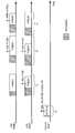
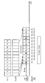
- FIG. 1 is an explanatory diagram of a UCI transmission operation according to Embodiment 2.1.
- three LAA SCells are shown.
- “PUCCH SCell” indicates an LAA SCell that can transmit PUCCH (set as a PUCCH cell).
- LAA SCell i and LAA SCell i + 1 indicate LAA SCells that cannot perform PUCCH transmission (not set as PUCCH cells).
- LAA SCell i has a smaller SCell index than both LAA SCell i + 1 and PUCCH SCell. Note that the application of this embodiment is not limited to the case where the UE uses three LAA SCells.
- the UE performs listening in the illustrated CCA period before transmitting a UL signal in each SCell, and performs UL transmission when determining that the channel is free.
- the period t 11 -t 14 shown in FIG. 1 is an exemplary period for explaining the UCI transmission operation, and the generation order and the length of the period are not limited.
- the UE performs all UCI (A / N, CSI (P-CSI, A-CSI)) of the unlicensed CC (in the PUCCH group), the SR), transmitted in a PUCCH LAA SCell based on LBT (exemplified in t 11) (PUCCH on LAA SCell ).
- the A-CSI of the SCell other than the PUCCH SCell may not be transmitted in the PUCCH SCell.
- UCI that does not need to be transmitted may not be transmitted even if it is the illustrated UCI.
- the t 11, A / N, CSI (P-CSI, A-CSI), or as at least one of the SR is transmitted.
- the UE shall transmit PUCCH according to PF4 / 5 in LAA SCell, but PFs other than these may be used. Note that the UE may transmit the one P-CSI according to PF 4 and / or 5 at the timing of transmitting only one P-CSI on the PUCCH, or the 1 according to the existing PF (for example, PF 2). One P-CSI may be transmitted.
- UE is scheduled at the timing when PUSCH is scheduled in LAA SCell and A / N and / or P-CSI is triggered (transmits A / N and / or P-CSI) in PUSCH of a particular cell of the LAA SCell, based on LBT transmits the a / N and / or P-CSI (exemplified in t 12).
- t 12 since the UE attempts to transmit UCI only in one of the scheduled LAA SCells, resource utilization efficiency can be improved by not transmitting UCI redundantly.
- UE utilizes the LAA SCell i as a particular cell.
- the specific cell may be, for example, the smallest predetermined identifier for the cell among the scheduled LAA SCells.
- the predetermined identifier may be a cell ID (cell identity), a physical cell ID, a virtual cell ID, a cell index (for example, an SCell index, an index dedicated to LAA SCell), or other identifiers. .
- the UE uses the PUSCH of all the scheduled LAA SCells based on the LBT. / transmits the N and / or P-CSI (exemplified in t 13). In this case, since the UE can attempt to transmit UCI having the same content in all scheduled LAA SCells, the possibility of successful transmission of UCI can be improved.
- the UE performs LBT on the PUSCH of the LAA SCell. transmitting the a-CSI based on (exemplified in t 14). In this case, by transmitting the A-CSI only in the cell where A-CSI is triggered, the communication overhead related to the A-CSI report can be distributed to each cell. Note that the UE may transmit A-CSI and A / N together (piggyback) when it has A / N to transmit.
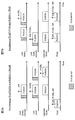
- FIG. 2 is an explanatory diagram of the UCI transmission operation according to Embodiment 2.2.
- FIG. 2 shows an example similar to FIG.
- the UE transmits UCI based on the LBT on the PUCCH on the LAA SCell (PUCCH SCell) at a timing (for example, TTI) at which at least one of A / N, P-CSI, and SR is to be transmitted (t 21 , T 23 , t 24 and t 25 ).
- a timing for example, TTI
- FIG. 2 shows an example in which the UE transmits PUCCH according to PF 4/5 in LAA SCell, but other PFs may be used. Note that the UE may transmit the one P-CSI according to PF 4 and / or 5 at the timing of transmitting only one P-CSI on the PUCCH, or the 1 according to the existing PF (for example, PF 2). One P-CSI may be transmitted.
- the UE transmits A-CSI based on the LBT on the PUSCH of the triggered cell (illustrated at t 22 and t 25 ). .
- A-CSI (A -CSI i) for LAA SCell i has been sent by the LAA SCell i.
- the UE may hold the UCI for a predetermined period (which may be referred to as a UCI holding period or a UCI holding period related to PUCCH). As a result, the UE can collectively transmit the UCI held so far at the timing when the LBT succeeds (the LBT result is free).
- the UCI may be retained by storing the UCI in a predetermined buffer area, for example.
- the UCI holding period may be defined as a period in which the UCI can be transmitted on the PUCCH starting from a time resource (for example, TTI) of the PUCCH that may be able to transmit a certain UCI first.
- the UCI retention period may be specified as a fixed value in advance in the specification, or upper layer signaling from the eNB (for example, RRC signaling, broadcast information (MIB (Master Information Block), SIB (System Information Block), etc.))
- the notification may be made by physical layer signaling (for example, downlink control information (DCI)) or a combination thereof.
- DCI downlink control information
- the UE may discard UCI that has been successfully transmitted even within the UCI retention period. On the other hand, even if the UCI has been successfully transmitted, the UE may hold the UCI within the UCI holding period.
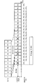
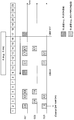
- FIG. 3 is a diagram illustrating an example of the UCI holding operation according to the modification of the second embodiment.
- FIG. 3 shows a downlink signal (DL Tx) received by the UE, an uplink resource of PUCCH SCell, and a UCI (A / N) to be transmitted.
- DL Tx downlink signal
- PUCCH SCell uplink resource of PUCCH SCell
- UCI UCI
- the TTI length is 1 ms, but the TTI length is not limited to this.
- the UE receives a downlink signal (downlink data) with continuous 12 TTIs.
- a / N (A / N j ) is generated and held in response to reception of the j-th TTI downlink signal.
- the UE generates and holds a corresponding A / N.
- the UCI holding period (X) is set to 9 ms. For this reason, each A / N j is discarded when 9 ms elapses after being held. That is, the maximum number of UCI (A / N) held in the buffer can be said to be the number obtained by dividing the UCI holding period by the TTI length.
- UE performs UL transmission (including transmission of UCI) based on LBT using PUCCH in XSCell after a predetermined time (for example, 4 ms) from reception of downlink data.
- “UCI to be transmitted” cannot be transmitted depending on the LBT result (TTI in which “X” is duplicated in “UL” in the figure), and therefore may indicate “UCI to be transmitted”. In this example, even if the UCI has been successfully transmitted, it is retained during the UCI retention period, and transmission is continued during the retention period.
- the UE can transmit UCI during the UCI holding period (X), the possibility that each UCI can be transmitted in the LAA SCell (XSCell) can be improved.
- the UE may similarly control the UCI transmission process based on the UCI holding period even when transmitting UCI using PUSCH, or transmitting using PUCCH and PUSCH.
- the UCI retention period may be set / specified individually for each type of UCI.
- the A / N UCI holding period, the P-CSI UCI holding period, the A-CSI UCI holding period, and the SR UCI holding period may be set / defined differently. However, they may be set / defined in the same way.
- UE operation movement when PUCCH transmission (PUCCH on LAA SCell) on LAA SCell is not set is prescribed
- a plurality of UCI transmission modes used to specify whether the UCI of each CC is transmitted by a license carrier or an unlicensed carrier are defined. Then, the eNB sets (notifies) which UCI transmission mode the UE performs transmission control by higher layer signaling (for example, RRC signaling), physical layer signaling (for example, DCI), or a combination thereof.
- higher layer signaling for example, RRC signaling
- physical layer signaling for example, DCI
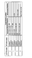
- FIG. 4 is a diagram illustrating an example of the UCI transmission mode according to the third embodiment.
- the UCI transmission mode 0 is a mode in which all UCIs related to the unlicensed CC are transmitted using the license CC.
- the UCI transmission mode 1 is a mode in which only A-CSI related to the unlicensed CC is transmitted by the unlicensed CC, and all other than that are transmitted by the license CC.
- the UCI transmission mode 2 is a mode in which CSI (P-CSI and A-CSI) related to the unlicensed CC is transmitted using the unlicensed CC, and A / N related to the unlicensed CC is transmitted using the license CC.
- the UCI transmission mode 3 is a mode in which all UCI related to the unlicensed CC is transmitted by the unlicensed CC.
- the SR of the unlicensed CC is not shown in FIG. 4, it may be transmitted, for example, in the CC to which the A / N of the unlicensed CC is transmitted, or is always transmitted in the license CC. Alternatively, it may be transmitted in a CC in which another UCI is transmitted.
- each transmission mode transmission control for UCI not specifically described is LTE Rel. It may be the same as the transmission control in 13 eCAs.
- PCell and license SCell n which are license CCs
- LAA SCell i (and LAA SCell i + 1 ) which are unlicensed CCs, and respective uplink signals are shown.
- LAA SCell i is a cell having the smallest SCell index among LAA SCells.
- the PCell can be read as the PUCCH cell of the license carrier.
- UCI transmission mode 0 regarding which license CC to transmit the A-CSI for the unlicensed CC may be defined in advance in the specification, or may be set in the UE by RRC signaling or the like.
- FIG. 5 is a diagram illustrating an example of transmission control according to the UCI transmission mode 1.
- the UE drops the P-CSI related to the unlicensed CC at the timing when the PUSCH is scheduled only for the unlicensed CC (FIG. 5A).
- FIG. 5A at the timing when PUSCH is scheduled only LAA SCell i, examples LAA SCell i about P-CSI (P-CSI i ) is dropped is shown.
- the UE performs P-CSI related to the unlicensed CC at the timing when the PUSCH is scheduled only to the unlicensed CC and PF3 is used in the PCell. Drop (FIG. 5B).
- P-CSI related to the unlicensed CC can be transmitted by the PUCSH of the license CC at the timing when the PUSCH is scheduled to the license CC.
- the UE may transmit the P-CSI related to the unlicensed CC only on the PUSCH of a specific cell, or may be transmitted on the PUSCH of all scheduled LAA SCells.
- the specific cell may be, for example, the smallest predetermined identifier for the cell among the scheduled LAA SCells.
- the predetermined identifier may be a cell ID, a physical cell ID, a virtual cell ID, a cell index (for example, an SCell index, an index dedicated to LAA SCell), or other identifiers.
- FIG. 6 is a diagram illustrating an example of transmission control according to the UCI transmission mode 2.
- FIG. 6A shows a case where PUCCH + PUSCH simultaneous transmission is not possible
- FIG. 6B shows a case where PUCCH + PUSCH simultaneous transmission is possible.
- P-CSI related to all unlicensed CCs is transmitted on the PUSCH of LAA SCell i regardless of whether or not simultaneous transmission of PUCCH + PUSCH is possible.
- the UE performs UCI transmission control using a newly defined operation.
- one specific LAA SCell is selected as a special LAA SCell (special LAA SCell) for UCI transmission.
- the special LAA SCell may be called, for example, XSCell.
- XSCell may be selected by UE and report information indicating XSCell to eNB.
- the reporting may be performed, for example, by higher layer signaling (eg, RRC signaling), physical layer signaling (UCI), or a combination thereof.
- the UE may select the XSCell based on a history of LBT results.
- the XSCell may be selected by the eNB and notify the UE of information indicating the XSCell.
- the notification may be performed, for example, by higher layer signaling (eg, RRC signaling), physical layer signaling (DCI, eg, UL grant), or a combination thereof.
- the eNB may select the XSCell based on, for example, any of the following (a) to (d) or a combination thereof: (A) Select uniformly and randomly, (B) A / N of each carrier, (C) history of UL LBT results reported from the UE, (D) When a Type B multicarrier LBT is used for the UL LBT, the CC selected to implement LBT category 4 (LBT to which random backoff is applied) and the XSCell are associated with each other.
- the UE transmits A / N and / or P-CSI of unlicensed CC only on PUSCH of XSCell based on LBT.
- the UE transmits UCI (A / N and / or P-CSI) on the unlicensed CC only at the timing when there is no PUCCH transmission on the license CC.
- the UE performs UCI transmission on the unlicensed CC regardless of the license CC.
- FIG. 7 is a diagram illustrating an example of transmission control according to the UCI transmission mode 3.
- FIG. 7A shows a case where PUCCH + PUSCH simultaneous transmission is impossible
- FIG. 7B shows a case where PUCCH + PUSCH simultaneous transmission is possible.
- XSCell is LAA SCell i in FIG. 7A and LAA SCell i + 1 in FIG. 7B.
- the A / N of the unlicensed CC is transmitted in the XSCell, and the A-CSI (A-CSI i ) of the cell is transmitted in the LAA SCell i .
- the UE gives priority to the PUCCH when there is a PUCCH transmission in the license CC.
- the UE transmits the UCI of the license CC using the license CC (PCell or PUCCH cell), and transmits the A / N and P-CSI of the unlicensed CC using the PUSCH of the XSCell.
- the UE transmits the A-CSI of the unlicensed CC in the cell where the measurement is triggered.
- the UE uses the UCI (for example, A / N and P-CSI) of the unlicensed CC for a predetermined period (time window for UCI retention) and first retention period (related to PUSCH). For example, the first UCI holding period) may be held.
- the UE transmits the held UCI together.
- the UE discards the UCI that has exceeded the first holding period.
- the first holding period may be defined as a period during which transmission on a PUSCH of a certain UCI (for example, A / N bit) is valid. Further, the first holding period may be defined as a fixed value in advance in the specification, or may be determined by eNB to higher layer signaling (for example, RRC signaling), physical layer signaling (DCI, for example, DL grant), or a combination thereof. , May be notified.
- higher layer signaling for example, RRC signaling
- DCI physical layer signaling
- the UE holds A / N during the first holding period even if it does not receive the UL grant that schedules the uplink resource.
- the first holding period may start from a time resource (for example, TTI) of a PUSCH of XSCell that may be able to transmit a certain UCI first, or a TTI (for example, a DL signal that has generated a certain UCI). It may be started from the received TTI).
- the UE uses the UCI (for example, A / N and P-CSI) of the unlicensed CC for a predetermined period (time window for UCI transmission (time window) for UCI transmission), a second retention period (second UCI retention period for PUSCH), etc.).
- a predetermined period time window for UCI transmission (time window) for UCI transmission
- second retention period second UCI retention period for PUSCH
- the second holding period may be defined as a period in which the UCI can be transmitted on the XSCell PUSCH, starting from a time resource (for example, TTI) of the XSCell PUSCH in which a certain UCI may be transmitted first.
- the second retention period may be defined as a fixed value in advance in the specification, or may be determined by eNB to higher layer signaling (for example, RRC signaling), physical layer signaling (DCI, for example, UL grant), or a combination thereof. , May be notified.
- the holding period until the UL grant is received may be the first holding period
- the holding period after receiving the UL grant may be the second holding period.
- both the holding period until the UL grant is received and the holding period after receiving the UL grant may be the first holding period (or the second holding period).
- the UE when receiving the UL grant, the UE may perform control so as to reset the elapsed time from the start of holding each UCI held.
- the UE may discard UCI that has been successfully transmitted even within the UCI retention period. On the other hand, even if the UCI has been successfully transmitted, the UE may hold the UCI within the UCI holding period.
- the UCI holding period, the first holding period, the second holding period, and the like may be individually set / defined for each type of UCI.
- FIG. 8 is a diagram illustrating an example of the UCI holding operation according to the UCI transmission mode 3 of the third embodiment.
- FIG. 8 shows a downlink signal (DL Tx) received by the UE, a UL grant received by the UE, an uplink resource of the PUSCH of XSCell, and a UCI (A / N) transmitted based on the UL grant. Yes.
- the TTI length is 1 ms, but the TTI length is not limited to this. The same applies to FIGS. 9 and 10 below.
- the UE receives a downlink signal (downlink data) with continuous 12 TTIs.
- a / N (A / N j ) is generated and held in response to reception of the j-th TTI downlink signal.
- the UE generates and holds a corresponding A / N.
- the UCI holding period (X) is set to 9 ms. For this reason, each A / N j is discarded when 9 ms elapses after being held.
- the UE also receives a UL grant that schedules XSCell uplink transmission using a TTI that receives downlink data.
- a UL grant that schedules XSCell uplink transmission using a TTI that receives downlink data.
- transmission of a transport block in one subframe is scheduled (single subframe scheduling).
- UE performs UL transmission (including UCI transmission) based on LBT in XSCell after a predetermined time (for example, 4 ms) from reception of UL grant.
- a predetermined time for example, 4 ms
- the UE since the UE can transmit UCI during the UCI holding period (X), the possibility of transmitting each UCI can be improved.
- FIG. 9 is a diagram illustrating another example of the UCI holding operation according to the UCI transmission mode 3 of the third embodiment.
- FIG. 9 shows a downlink signal (DL Tx) received by the UE, a UL grant received by the UE, an uplink resource of the PUSCH of XSCell, and a UCI (A / N) transmitted based on the UL grant. Yes.
- DL Tx downlink signal
- UL grant received by the UE
- a / N uplink resource of the PUSCH of XSCell
- UCI A / N
- the UE receives a downlink signal (downlink data) with continuous 12 TTIs as in the example of FIG.
- the first holding period (Y) is set to 6 ms
- the second holding period (X) is set to 9 ms. For this reason, each A / N j is discarded when 9 ms elapses after being held.
- UL grant is transmitted in TTI in which the sixth and twelfth downlink signals are transmitted.
- transmission of transport blocks in a plurality of subframes is scheduled (multi-subframe scheduling).
- transmission of UL subframes corresponding to the same TTI as the second holding period is instructed by the UL grant, and the UE can improve the possibility of transmitting each UCI.
- FIG. 10 is a diagram illustrating still another example of the UCI holding operation according to the UCI transmission mode 3 of the third embodiment.
- FIG. 10 is based on the downlink signal (DL Tx) received by the UE, the UL grant received by the UE, the UCI (A / N) held for transmission (waiting for transmission), and the UL grant.
- UCI (A / N) to be transmitted is shown.
- FIG. 10 illustrates an example in which the eNB tries to transmit a downlink signal (downlink data) with continuous 12 TTIs, but some downlink signals cannot be transmitted because the LBT result is busy.
- the first holding period (Y) is set to 6 ms, and the second holding period (X) is not set. Therefore, each A / N j is discarded when 6 ms elapses without receiving a UL grant or when 6 ms elapses after transmission becomes possible.
- a / N 1 to A / N 4 are held as UCIs that can be transmitted. Further, A / N 4 to A / N 6 are held at the transmission timing based on the second UL grant shown in FIG.
- the UE set with the first retention period (Y) can improve the possibility of transmitting each UCI.
- the UCI held is not limited to A / N and P-CSI.
- at least one of A / N, P-CSI, A-CSI, and SR may be controlled for transmission based on the first holding period and / or the second holding period.
- Control signal for UCI transmission mode As a control signal for setting the UCI transmission mode described in the third embodiment to the UE, it is considered to use UL grant, PDCCH (common PDCCH (common PDCCH)) transmitted in a common search space, or the like. It is done.
- PDCCH common PDCCH (common PDCCH)
- information on the UCI transmission mode may be notified by the UL grant.
- this information for example, 2-bit information indicating the UCI transmission modes 0-3 may be used.
- information for specifying a special LAA SCell (XSCell) for UCI transmission according to UCI transmission mode 3 may be notified by the UL grant.
- information of a predetermined number of bits for example, the number of LAA SCells, the maximum number of LAA SCells, etc. may be used.
- information on the first holding period and / or the second holding period according to the UCI transmission mode 3 may be notified using a common PDCCH (for example, DCI format 1C).
- the common PDCCH may be transmitted on the PCell, or may be transmitted on the SCC and / or LAA SCell of the license CC.
- a new field in the DCI format may be specified, or an existing field (for example, a resource allocation field) may be replaced and used.
- a codebook size also referred to as CBS: Code Book Size, HARQ codebook size, etc.
- CBS Code Book Size, HARQ codebook size, etc.
- HARQ-ACK transmission is performed in LAA SCell.
- PUCCH transmission PUCCH on LAA SCell
- UCI such as HARQ-ACK is transmitted on the PUSCH.
- the present embodiment is not limited to this, and can also be applied to the case where PUCCH transmission is performed.
- the user terminal When transmitting a HARQ-ACK for DL transmission, the user terminal performs transmission with a predetermined codebook size (also called an ACK / NACK bit string or A / N bit size).
- a predetermined codebook size also called an ACK / NACK bit string or A / N bit size.
- the size of the codebook (ACK / NACK bit string) of HARQ-ACK transmitted by PUCCH is determined semi-static (semi-static) based on the information on the number of CCs notified by higher layer signaling. .
- the entire A / N bit is based on the number of CCs configured by RRC signaling and TM (Transmission Mode) indicating whether MIMO (Multiple Input Multiple Output) is applicable in each CC.
- the size is fixed.
- the size of the entire A / N bit string transmitted by PUCCH is determined based on the number of DL subframes subject to A / N per UL subframe.
- the present inventors have found that the HARQ-ACK codebook size is determined in consideration of the A / N retention period when HARQ-ACK transmission is performed in LAA SCell.
- the following describes the case where the codebook size is fixedly set (fixed codebook size) when HARQ-ACK transmission is performed in LAA SCell, and the case where it is dynamically set (dynamic codebook size).
- a user terminal transmits an A / N (retransmission control information) for a downlink signal using LAA SCell (a carrier that performs listening before transmission).
- the user terminal sets the codebook size used for A / N transmission based on the A / N holding time in the user terminal.
- the user terminal may set a fixed codebook size based on a period for which A / N is held in the user terminal (A / N holding period).
- the holding period of A / N includes a period of holding A / N from the TTI scheduled by the UL grant (second holding period (X)) and an A of the downlink signal from the TTI that has received the downlink signal.
- / N may be at least one of the periods (first retention period (Y)).
- the user terminal holds A / N only for the second holding period (X) from the scheduled TTI by the UL grant. For this reason, even if the user terminal fails to listen in the scheduled TTI, the user terminal may transmit A / N if the listening succeeds in the subsequent TTI within the second holding period (X). it can. When the second holding period (X) elapses, the user terminal discards A / N.
- the user terminal holds A / N only for the first holding period (Y) from the TTI that received the downlink signal. For this reason, even if the user terminal does not receive the UL grant in the TTI that has received the downlink signal (downlink data, downlink data channel (for example, PDSCH: Physical Downlink Shared Channel)), the user terminal is in the first holding period (Y).
- the UL grant is successfully received in the subsequent TTI, the A / N can be transmitted by the TTI scheduled by the UL grant.
- the user terminal discards A / N.
- the first holding period (Y) is made equal to the TTI length (for example, 1 ms), it may be interpreted that the first holding period (Y) is not set. In this case, the user terminal cannot transmit the A / N of the downlink signal unless receiving the UL grant with the TTI that has received the downlink signal.
- the user terminal may A fixed codebook size may be set.
- the number of CCs may be the number of cells (CCs) that need to transmit A / N of the downlink signal, and is not limited to the number of LAA Scells or the number of CCs set in the user terminal. . Further, the number of CCs may be the number of CCs in the UCI cell group.
- the user terminal may set a fixed codebook size based on the following formula (1).
- X is the second holding period
- Y is the first holding period
- N is the number of cells (CC) that generate A / N of the downlink signal.
- Formula (1) is only an illustration and is not restricted to this. Various parameters not described in Equation (1) may be considered.
- X, Y, and N are set by higher layer signaling, they may be specified by physical layer signaling or may be determined by a combination of higher layer signaling and physical layer signaling. Further, the CBS itself may be set by higher layer signaling or may be designated by physical layer signaling.
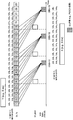
- FIG. 17 is a diagram illustrating an example of a codebook size determination method according to the fourth embodiment.
- the downlink signal (DL Tx) received by the UE, the UL grant received by the UE, the uplink resource of the PUSCH of the XSCell, the UCI (A / N) transmitted based on the UL grant, the first A TTI held in each TTI based on the holding period (Y) and a TTI held in each TTI based on the second holding period (X) are shown.
- the TTI length is 1 ms, but the TTI length is not limited to this.
- FIGS. 18 and 19 the same applies to FIGS. 18 and 19 below.
- FIG. 17 it is assumed that UL transmission in a TTI after 4 TTI is scheduled by the UL grant, but UL transmission scheduled by the UL grant is not limited to after 4 TTI.
- FIG. 17 illustrates the case of single subframe scheduling in which UL transmission in a single subframe is scheduled by UL grant in a single subframe, but UL transmission in a plurality of subframes is performed by the UL grant.
- the present invention can also be applied appropriately in the case of multi-subframe scheduling in which is scheduled.
- the first holding period (Y) is set to 6 ms
- the second holding period (X) is set to 9 ms.
- the set values of the first holding period (Y) and the second holding period (X) are not limited to this.
- the number (N) of cells (CC) that generate the A / N of the downlink signal is set to 1, but is not limited thereto.
- the user terminal receives a downlink signal (downlink data) at successive 18 TTIs.
- a / N j of the downlink signal is generated.
- the user terminal holds the generated A / N j for the first holding period (Y) (here, 6 ms).
- Y the first holding period
- the A / N 1 of the downlink signal of the first TTI is retained from the first TTI to the sixth TTI, and is discarded when the UL grant is not received by the sixth TTI.
- the A / N j of the j-th TTI downstream signal is held from the j-th TTI to the j + (Y ⁇ 1) -th TTI.
- a / N j is discarded if no UL grant is received by the j + (Y ⁇ 1) th TTI.
- a / N j is transmitted using the PUSCH scheduled by the UL grant.
- a / N 1 to A / N 6 are transmitted using 6 bits of the 12-bit codebook in the 10th TTI. Is done. In this case, the remaining 6 bits are unused, and for example, a default value (for example, NACK) may be set.
- a / N 7 to A / N 12 of the downlink signals of the 7th to 12th TTI are held based on the first holding period (Y). Yes.
- the downlink signals of the 1st to 6th TTIs based on the second holding period (X) are used.
- a / N 1 to A / N 6 are also held. Therefore, in the 16th TTI, A / N 1 to A / N 12 are transmitted using all the bits of the 12-bit codebook.
- the A / N 13 to A / N 18 of the 13th to 18th TTI downlink signals are held based on the first holding period (Y). Yes.
- the downlink signals of the 7th to 12th TTIs based on the second holding period (X) are used.
- a / N 7 to A / N 12 are also held. Therefore, in the 20th TTI, A / N 7 to A / N 18 are transmitted using all the bits of the 12-bit codebook.
- the code book size is determined in consideration of the A / N holding period (for example, the second holding period (X)).
- the codebook size is controlled depending on whether or not the UL subframe is included in a range from the SF # n to a predetermined period.
- the UL subframe refers to at least a UL subframe in which HARQ-ACK transmission is performed (including a case where transmission is not possible as a result of LBT).
- the predetermined period can be set within a range (for example, X ⁇ 1 or less) in consideration of the A / N holding period. Of course, it is not limited to X-1.
- the user terminal determines whether there is a UL subframe (for example, SF # m) that transmits HARQ-ACK within a range of (X-1) ms before SF # n that performs HARQ-ACK transmission. Change the codebook size. Specifically, when there is a UL subframe (SF # m) for transmitting HARQ-ACK within a range of (X-1) ms before SF # n for performing HARQ-ACK transmission, the SF # m The codebook size of SF # n is determined in consideration of the codebook size of HARQ-ACK. There may be a plurality of SF # m.
- the user terminal can determine the codebook size of SF # n regardless of the LBT result in SF # m (only according to the position of SF # m).
- the codebook size in SF # n may be controlled in consideration of the UL transmission result (LBT result) of SF # m. For example, when A / N can be transmitted by SF # m (LBT idle), the codebook size of SF # m may not be considered when determining the codebook size in SF # n.
- the codebook size of SF # n is determined without considering the codebook sizes of other UL subframes.
- the above-described second holding period (X) is assumed as the holding period, but is not limited thereto. You may consider the 1st holding
- FIG. 18 shows an example in which the codebook size is dynamically changed in consideration of the A / N retention period.
- the A / N for the DL signal (for example, PDSCH) transmitted by SF # 2- # 5 is transmitted by SF # 9
- the A / N for the DL signal transmitted by SF # 11- # 14 is transmitted.
- the case of transmitting with SF # 17 is shown.
- a / N transmission (codebook size, etc.) in each UL subframe SF # 9, # 17 is controlled based on DAI (Downlink Assignment Indicator (Index)) included in the DL signal.
- DAI included in the DL signal for example, DCI
- a counter DAI Counter DAI, C-DAI
- a total DAI Total DAI, T-DAI
- the counter DAI corresponds to information (count value) used for counting the scheduled DL signal (corresponding to the number of CCs in FDD).
- the total DAI corresponds to information indicating the number of scheduled DL signals (corresponding to the number of CCs in FDD).
- the radio base station notifies the user terminal including the counter DAI and the total DAI in the downlink control information of each CC.
- the counter DAI and / or total DIA can be specified using 2 bits.
- the user terminal can determine the number of DL signals (codebook size) scheduled based on the notified total DAI and can determine the A / N of each DL signal based on the counter DAI.
- the DCI of each DL signal transmitted in SF # 2- # 5 includes a different counter DAI (here 1-8) and a common total DAI (here 8). .
- the user terminal determines that the DL signal corresponding to the counter DAI corresponding to 5 is missed.
- the user terminal determines the A / N and codebook size (here, 8) of each DL subframe based on the counter DAI and the total DAI, and performs a plurality of A / N transmissions in SF # 9.
- the DCI of each DL signal transmitted in SF # 11- # 14 includes a different counter DAI (here, 1-7) and a common total DAI (here, 7). .
- the user terminal can determine that the DL signal whose counter DAI corresponds to 7 has been missed.
- the user terminal determines the A / N and codebook size (here, 7) of each DL subframe based on the counter DAI and the total DAI, and performs a plurality of A / N transmissions in SF # 17.
- the code book size can be dynamically changed in consideration of the number of scheduled DL signals.
- the codebook size of the SF # m is determined in consideration of (for example, total DAI). For example, it is assumed that the HARQ-ACK codebook size in the UL subframe of SF # 17 in FIG. 18 is determined.
- a predetermined period for example, X-1 or less.
- the user terminal combines the code book size in SF # 9 (here, 8) and the A / N codebook size (here, 7) for the DL signals in SF # 11- # 14.
- the user terminal then feeds back the A / N for the SF signal of SF # 2- # 5 and the A / N for the DL signal of SF # 11- # 14 using the codebook size.
- the code of the SF # m is determined without considering the book size. For example, it is assumed that the codebook size in the UL subframe of SF # 22 in FIG. 19 is determined. Note that FIG. 19 corresponds to the case where the subframe of SF # 17 in FIG. 18 is replaced with SF # 22.
- a predetermined period for example, X-1 or less.
- the user terminal determines the codebook size in SF # 22 as the A / N codebook size (here, 7) for the DL signals of SF # 11- # 14. Then, the user terminal feeds back an A / N for the DL signals of SF # 11- # 14 using the codebook size.
- the SF # 22 9 performs A / N transmission without considering A / N.
- the codebook size in consideration of the A / N retention period, it is possible to suppress a decrease in A / N transmission opportunities due to the LBT result (LBT busy) and to reduce the overhead of the codebook size. Can be suppressed.
- Wireless communication system Wireless communication system
- a wireless communication method according to any and / or combination of the above embodiments of the present invention is applied.
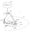
- FIG. 11 is a diagram illustrating an example of a schematic configuration of a wireless communication system according to an embodiment of the present invention.
- the wireless communication system 1 carrier aggregation (CA) and / or dual connectivity (DC) in which a plurality of basic frequency blocks (component carriers) having the system bandwidth of the LTE system as one unit can be applied.
- the wireless communication system 1 also has a wireless base station (for example, LTE-U base station) that can use an unlicensed band.
- a wireless base station for example, LTE-U base station
- the wireless communication system 1 includes SUPER 3G, LTE-A (LTE-Advanced), IMT-Advanced, 4G (4th generation mobile communication system), 5G (5th generation mobile communication system), FRA (Future Radio Access), etc. May be called.
- a radio communication system 1 shown in FIG. 11 includes a radio base station 11 that forms a macro cell C1, and a radio base station 12 (12a-12c) that is arranged in the macro cell C1 and forms a small cell C2 that is narrower than the macro cell C1. I have. Moreover, the user terminal 20 is arrange
- LTE-U unlicensed band
- the user terminal 20 can be connected to both the radio base station 11 and the radio base station 12. It is assumed that the user terminal 20 uses the macro cell C1 and the small cell C2 that use different frequencies simultaneously by CA or DC. For example, assist information (for example, DL signal configuration) regarding the radio base station 12 (for example, LTE-U base station) that uses the unlicensed band is transmitted from the radio base station 11 that uses the license band to the user terminal 20. can do. Further, when CA is performed in the license band and the unlicensed band, it is possible to adopt a configuration in which one radio base station (for example, the radio base station 11) controls the schedules of the license band cell and the unlicensed band cell.
- assist information for example, DL signal configuration
- LTE-U base station LTE-U base station
- the user terminal 20 may be connected to the radio base station 12 without being connected to the radio base station 11.
- the wireless base station 12 using the unlicensed band may be connected to the user terminal 20 in a stand-alone manner.
- the radio base station 12 controls the schedule of the unlicensed band cell.
- Communication between the user terminal 20 and the radio base station 11 can be performed using a carrier having a relatively low frequency band (for example, 2 GHz) and a narrow bandwidth (referred to as an existing carrier or a legacy carrier).
- a carrier having a relatively high frequency band for example, 3.5 GHz, 5 GHz, etc.
- the same carrier may be used.
- the configuration of the frequency band used by each radio base station is not limited to this.
- a wired connection for example, an optical fiber compliant with CPRI (Common Public Radio Interface), an X2 interface, etc.
- a wireless connection It can be set as the structure to do.
- the radio base station 11 and each radio base station 12 are connected to the higher station apparatus 30 and connected to the core network 40 via the higher station apparatus 30.
- the upper station device 30 includes, for example, an access gateway device, a radio network controller (RNC), a mobility management entity (MME), and the like, but is not limited thereto.
- RNC radio network controller
- MME mobility management entity
- Each radio base station 12 may be connected to the higher station apparatus 30 via the radio base station 11.
- the radio base station 11 is a radio base station having a relatively wide coverage, and may be called a macro base station, an aggregation node, an eNB (eNodeB), a transmission / reception point, or the like.
- the radio base station 12 is a radio base station having local coverage, and includes a small base station, a micro base station, a pico base station, a femto base station, a HeNB (Home eNodeB), an RRH (Remote Radio Head), and transmission / reception. It may be called a point.
- the radio base stations 11 and 12 are not distinguished, they are collectively referred to as a radio base station 10.
- the radio base stations 10 that share and use the same unlicensed band are configured to be synchronized in time.
- Each user terminal 20 is a terminal that supports various communication methods such as LTE and LTE-A, and may include not only a mobile communication terminal but also a fixed communication terminal.
- orthogonal frequency division multiple access (OFDMA) is applied to the downlink, and single carrier-frequency division multiple access (SC-FDMA) is used for the uplink.
- SC-FDMA single carrier-frequency division multiple access
- Carrier Frequency Division Multiple Access is applied.
- OFDMA is a multi-carrier transmission scheme that performs communication by dividing a frequency band into a plurality of narrow frequency bands (subcarriers) and mapping data to each subcarrier.
- SC-FDMA is a single-carrier transmission scheme that reduces interference between terminals by dividing the system bandwidth into bands consisting of one or continuous resource blocks for each terminal and using a plurality of terminals with mutually different bands. is there.
- the uplink and downlink radio access methods are not limited to these combinations.
- downlink channels include a downlink shared channel (PDSCH) shared by each user terminal 20, a broadcast channel (PBCH: Physical Broadcast Channel), a downlink L1 / L2 control channel, and the like. Used. User data, higher layer control information, SIB (System Information Block), etc. are transmitted by PDSCH. Also, MIB (Master Information Block) is transmitted by PBCH.
- PDSCH downlink shared channel
- PBCH Physical Broadcast Channel
- SIB System Information Block
- MIB Master Information Block
- Downlink L1 / L2 control channels include PDCCH (Physical Downlink Control Channel), EPDCCH (Enhanced Physical Downlink Control Channel), PCFICH (Physical Control Format Indicator Channel), PHICH (Physical Hybrid-ARQ Indicator Channel), and the like.
- Downlink control information (DCI: Downlink Control Information) including scheduling information of PDSCH and PUSCH is transmitted by PDCCH.
- the number of OFDM symbols used for PDCCH is transmitted by PCFICH.
- the HAICH transmission confirmation information (ACK / NACK) for PUSCH is transmitted by PHICH.
- the EPDCCH is frequency-division multiplexed with the PDSCH, and is used for transmission of DCI and the like as with the PDCCH.
- an uplink shared channel (PUSCH: Physical Uplink Shared Channel) shared by each user terminal 20, an uplink L1 / L2 control channel (PUCCH: Physical Uplink Control Channel), a random access channel (PRACH: Physical Random Access Channel) is used.
- PUSCH may be referred to as an uplink data channel.
- User data and higher layer control information are transmitted by PUSCH.
- downlink radio quality information (CQI: Channel Quality Indicator), delivery confirmation information (ACK / NACK), and the like are transmitted by PUCCH.
- CQI Channel Quality Indicator
- ACK / NACK delivery confirmation information
- a random access preamble for establishing connection with a cell is transmitted by the PRACH.
- a cell-specific reference signal CRS
- CSI-RS channel state information reference signal
- DMRS Demodulation Reference Signal
- a measurement reference signal SRS: Sounding Reference Signal
- a demodulation reference signal DMRS
- the DMRS may be referred to as a user terminal specific reference signal (UE-specific Reference Signal). Further, the transmitted reference signal is not limited to these.
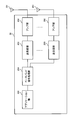
- FIG. 12 is a diagram illustrating an example of the overall configuration of a radio base station according to an embodiment of the present invention.
- the radio base station 10 includes a plurality of transmission / reception antennas 101, an amplifier unit 102, a transmission / reception unit 103, a baseband signal processing unit 104, a call processing unit 105, and a transmission path interface 106.
- the transmission / reception antenna 101, the amplifier unit 102, and the transmission / reception unit 103 may each be configured to include one or more.
- User data transmitted from the radio base station 10 to the user terminal 20 via the downlink is input from the higher station apparatus 30 to the baseband signal processing unit 104 via the transmission path interface 106.
- PDCP Packet Data Convergence Protocol
- RLC Radio Link Control
- MAC Medium Access
- Retransmission control for example, HARQ (Hybrid Automatic Repeat reQuest) transmission processing
- HARQ Hybrid Automatic Repeat reQuest
- the downlink control signal is also subjected to transmission processing such as channel coding and inverse fast Fourier transform, and is transferred to the transmission / reception unit 103.
- the transmission / reception unit 103 converts the baseband signal output by precoding for each antenna from the baseband signal processing unit 104 to a radio frequency band and transmits the converted signal.
- the radio frequency signal frequency-converted by the transmission / reception unit 103 is amplified by the amplifier unit 102 and transmitted from the transmission / reception antenna 101.
- the transmission / reception unit 103 can transmit / receive UL / DL signals in an unlicensed band.
- the transmission / reception unit 103 may be capable of transmitting / receiving UL / DL signals in a license band.
- the transmission / reception unit 103 can be configured by a transmitter / receiver, a transmission / reception circuit, or a transmission / reception device which is described based on common recognition in the technical field according to the present invention.
- the transmission / reception part 103 may be comprised as an integral transmission / reception part, and may be comprised from a transmission part and a receiving part.
- the radio frequency signal received by the transmission / reception antenna 101 is amplified by the amplifier unit 102.
- the transmission / reception unit 103 receives the uplink signal amplified by the amplifier unit 102.
- the transmission / reception unit 103 converts the frequency of the received signal into a baseband signal and outputs it to the baseband signal processing unit 104.
- the baseband signal processing unit 104 performs Fast Fourier Transform (FFT) processing, Inverse Discrete Fourier Transform (IDFT) processing, and error correction on user data included in the input upstream signal. Decoding, MAC retransmission control reception processing, RLC layer and PDCP layer reception processing are performed and transferred to the upper station apparatus 30 via the transmission path interface 106.
- the call processing unit 105 performs call processing such as communication channel setting and release, state management of the radio base station 10, and radio resource management.
- the transmission path interface 106 transmits and receives signals to and from the higher station apparatus 30 via a predetermined interface.
- the transmission path interface 106 transmits / receives signals (backhaul signaling) to / from other radio base stations 10 via an interface between base stations (for example, an optical fiber compliant with CPRI (Common Public Radio Interface), X2 interface). May be.
- CPRI Common Public Radio Interface
- X2 interface May be.
- the transmission / reception part 103 is licensed CC and / or unlicensed CC with respect to the user terminal 20, PUCCH cell setting information, information on the possibility of simultaneous transmission of PUCCH and PUSCH, information on UCI transmission mode, and UCI holding period Downlink control information (DCI) including information and / or higher layer signaling (for example, RRC signaling) is transmitted.
- the transmission / reception part 103 can receive PUSCH from the user terminal 20 at least by the unlicensed CC.
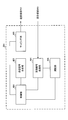
- FIG. 13 is a diagram illustrating an example of a functional configuration of a radio base station according to an embodiment of the present invention. Note that FIG. 13 mainly shows functional blocks of characteristic portions in the present embodiment, and the wireless base station 10 also has other functional blocks necessary for wireless communication.
- the baseband signal processing unit 104 includes at least a control unit (scheduler) 301, a transmission signal generation unit 302, a mapping unit 303, a reception signal processing unit 304, and a measurement unit 305. These configurations may be included in the radio base station 10, and a part or all of the configurations may not be included in the baseband signal processing unit 104.
- the control unit (scheduler) 301 controls the entire radio base station 10. When scheduling is performed by one control unit (scheduler) 301 for the license band and the unlicensed band, the control unit 301 controls communication between the license band cell and the unlicensed band cell.
- the control unit 301 may be a controller, a control circuit, or a control device described based on common recognition in the technical field according to the present invention.
- the control unit 301 controls signal generation by the transmission signal generation unit 302 and signal allocation by the mapping unit 303, for example.
- the control unit 301 also controls signal reception processing by the reception signal processing unit 304 and signal measurement by the measurement unit 305.
- the control unit 301 controls scheduling (for example, resource allocation) of system information, a downlink data signal transmitted on the PDSCH, and a downlink control signal transmitted on the PDCCH and / or EPDCCH. It also controls scheduling of synchronization signals (PSS (Primary Synchronization Signal) / SSS (Secondary Synchronization Signal)) and downlink reference signals such as CRS, CSI-RS, and DMRS.
- PSS Primary Synchronization Signal
- SSS Secondary Synchronization Signal
- the control unit 301 also transmits an uplink data signal transmitted on the PUSCH, an uplink control signal transmitted on the PUCCH and / or PUSCH (for example, a delivery confirmation signal (HARQ-ACK)), a random access preamble transmitted on the PRACH, Controls scheduling of uplink reference signals and the like.
- an uplink data signal transmitted on the PUSCH for example, an uplink control signal transmitted on the PUCCH and / or PUSCH (for example, a delivery confirmation signal (HARQ-ACK)), a random access preamble transmitted on the PRACH, Controls scheduling of uplink reference signals and the like.
- HARQ-ACK delivery confirmation signal
- the control unit 301 transmits, to the transmission signal generation unit 302 and the mapping unit 303, a downlink signal (for example, unlicensed CC) in a carrier that performs listening before downlink transmission (for example, unlicensed CC).
- a downlink signal for example, unlicensed CC
- a carrier that performs listening before downlink transmission for example, unlicensed CC
- PDCCH / EPDCCH may be controlled.
- the control unit 301 acquires UE capability information related to whether or not PF4 / 5 is supported in at least one LBT carrier from the received signal processing unit 304, determines the PUCCH cell of the LAA SCell based on the capability information, and You may control to transmit the PUCCH cell setting information regarding a cell to the user terminal 20.
- the control unit 301 may perform control so as to transmit to the user terminal 20 information regarding whether or not PUCCH and PUSCH can be transmitted simultaneously, information about the UCI transmission mode, information about the UCI holding period, and the like.
- control unit 301 may determine in which cell the user terminal transmits the UCI based on various types of information transmitted to the user terminal 20, and may perform reception processing and scheduling. .
- control unit 301 is based on the A / N (retransmission control information) holding time (for example, at least one of the first holding time (Y) and the second holding time (X)) in the user terminal 20.
- the codebook size used for A / N transmission may be controlled (determined).
- control unit 301 may control the codebook size based on the number of CCs.
- the codebook size may be a fixed size uniquely determined by each TTI (fixed codebook size, see FIG. 17), or may be a dynamically changed size (dynamic codebook size, FIGS. 18 and 19). reference).
- the fixed codebook size may be equal to the maximum number of A / Ns that are expected to be transmitted in each TTI.
- the transmission signal generation unit 302 generates a downlink signal (downlink control signal, downlink data signal, downlink reference signal, etc.) based on an instruction from the control unit 301, and outputs it to the mapping unit 303.
- the transmission signal generation unit 302 can be configured by a signal generator, a signal generation circuit, or a signal generation device described based on common recognition in the technical field according to the present invention.
- the transmission signal generation unit 302 generates, for example, a DL assignment (DL grant) for notifying downlink signal allocation information and a UL grant for notifying uplink signal allocation information based on an instruction from the control unit 301.
- the downlink data signal is subjected to coding processing and modulation processing according to a coding rate, a modulation scheme, and the like determined based on channel state information (CSI: Channel State Information) from each user terminal 20.
- CSI Channel State Information
- the mapping unit 303 maps the downlink signal generated by the transmission signal generation unit 302 to a predetermined radio resource based on an instruction from the control unit 301, and outputs it to the transmission / reception unit 103.
- the mapping unit 303 can be configured by a mapper, a mapping circuit, or a mapping device described based on common recognition in the technical field according to the present invention.
- the reception signal processing unit 304 performs reception processing (for example, demapping, demodulation, decoding, etc.) on the reception signal input from the transmission / reception unit 103.
- the received signal is, for example, an uplink signal (uplink control signal, uplink data signal, uplink reference signal, etc.) transmitted from the user terminal 20.
- the reception signal processing unit 304 can be configured by a signal processor, a signal processing circuit, or a signal processing device described based on common recognition in the technical field according to the present invention.
- the reception signal processing unit 304 outputs the information decoded by the reception processing to the control unit 301. For example, when receiving PUCCH including HARQ-ACK, HARQ-ACK is output to control section 301.
- the reception signal processing unit 304 outputs the reception signal and the signal after reception processing to the measurement unit 305.
- the measurement unit 305 performs measurement on the received signal.
- the measurement part 305 can be comprised from the measuring device, measurement circuit, or measurement apparatus demonstrated based on common recognition in the technical field which concerns on this invention.
- the measurement unit 305 Based on an instruction from the control unit 301, the measurement unit 305 performs LBT on a carrier (for example, an unlicensed band) in which LBT is set, and the LBT result (for example, whether the channel state is free or busy). May be output to the control unit 301.
- a carrier for example, an unlicensed band
- the LBT result for example, whether the channel state is free or busy
- the measurement unit 305 may, for example, receive power (for example, RSRP (Reference Signal Received Power)), received signal strength (for example, RSSI (Received Signal Strength Indicator)), and reception quality (for example, RSRQ (Reference). Signal Received Quality)) and channel status may be measured.
- the measurement result may be output to the control unit 301.
- FIG. 14 is a diagram illustrating an example of the overall configuration of a user terminal according to an embodiment of the present invention.
- the user terminal 20 includes a plurality of transmission / reception antennas 201, an amplifier unit 202, a transmission / reception unit 203, a baseband signal processing unit 204, and an application unit 205.
- the transmission / reception antenna 201, the amplifier unit 202, and the transmission / reception unit 203 may each be configured to include one or more.
- the radio frequency signal received by the transmission / reception antenna 201 is amplified by the amplifier unit 202.
- the transmission / reception unit 203 receives the downlink signal amplified by the amplifier unit 202.
- the transmission / reception unit 203 converts the frequency of the received signal into a baseband signal and outputs it to the baseband signal processing unit 204.
- the transmission / reception unit 203 can transmit / receive UL / DL signals in an unlicensed band.
- the transmission / reception unit 203 may be capable of transmitting / receiving UL / DL signals in a license band.
- the transmission / reception unit 203 can be composed of a transmitter / receiver, a transmission / reception circuit, or a transmission / reception device, which are described based on common recognition in the technical field according to the present invention.
- the transmission / reception unit 203 may be configured as an integral transmission / reception unit, or may be configured from a transmission unit and a reception unit.
- the baseband signal processing unit 204 performs FFT processing, error correction decoding, retransmission control reception processing, and the like on the input baseband signal.
- the downlink user data is transferred to the application unit 205.
- the application unit 205 performs processing related to layers higher than the physical layer and the MAC layer.
- broadcast information in the downlink data is also transferred to the application unit 205.
- uplink user data is input from the application unit 205 to the baseband signal processing unit 204.
- the baseband signal processing unit 204 performs transmission / reception by performing retransmission control transmission processing (for example, HARQ transmission processing), channel coding, precoding, discrete Fourier transform (DFT) processing, IFFT processing, and the like. Is transferred to the unit 203.
- the transmission / reception unit 203 converts the baseband signal output from the baseband signal processing unit 204 into a radio frequency band and transmits it.
- the radio frequency signal frequency-converted by the transmission / reception unit 203 is amplified by the amplifier unit 202 and transmitted from the transmission / reception antenna 201.
- the transceiver unit 203 receives, from the radio base station 10, the license CC and / or the unlicensed CC, PUCCH cell setting information, information on whether PUCCH and PUSCH can be transmitted simultaneously, information on the UCI transmission mode, information on the UCI holding period And / or higher layer signaling (eg, RRC signaling) is received. Further, the transmission / reception unit 203 can transmit the PUSCH to the radio base station 10 with at least the unlicensed CC.
- FIG. 15 is a diagram illustrating an example of a functional configuration of a user terminal according to an embodiment of the present invention. Note that FIG. 15 mainly shows functional blocks of characteristic portions in the present embodiment, and the user terminal 20 also has other functional blocks necessary for wireless communication.
- the baseband signal processing unit 204 included in the user terminal 20 includes at least a control unit 401, a transmission signal generation unit 402, a mapping unit 403, a reception signal processing unit 404, and a measurement unit 405. Note that these configurations may be included in the user terminal 20, and some or all of the configurations may not be included in the baseband signal processing unit 204.
- the control unit 401 controls the entire user terminal 20.
- the control unit 401 can be composed of a controller, a control circuit, or a control device described based on common recognition in the technical field according to the present invention.
- the control unit 401 controls, for example, signal generation by the transmission signal generation unit 402 and signal allocation by the mapping unit 403.
- the control unit 401 controls signal reception processing by the reception signal processing unit 404 and signal measurement by the measurement unit 405.
- the control unit 401 obtains, from the received signal processing unit 404, a downlink control signal (a signal transmitted by PDCCH / EPDCCH) and a downlink data signal (a signal transmitted by PDSCH) transmitted from the radio base station 10.
- the control unit 401 generates an uplink control signal (for example, an acknowledgment signal (HARQ-ACK)) or an uplink data signal based on a downlink control signal, a result of determining whether retransmission control is necessary for the downlink data signal, or the like.
- HARQ-ACK acknowledgment signal
- the control unit 401 transmits, to the transmission signal generation unit 402 and the mapping unit 403, an uplink signal (for example, PUCCH, etc.) in a carrier (LBT carrier) that performs listening before uplink transmission.
- PUSCH a carrier
- the control unit 401 Based on the information (PUCCH cell setting information) regarding whether or not at least one of the LBT carriers is a cell (PUCCH cell, PUCCH SCell) that transmits PUCCH, the control unit 401 acquires the LAA. Judgment is made on whether or not PUCCH can be transmitted on the SCell, and transmission of UCI in each LAA SCell is controlled.
- the control unit 401 can acquire, from the received signal processing unit 404, information on whether or not simultaneous transmission of an uplink control channel (for example, PUCCH) and an uplink shared channel (for example, PUSCH) is possible.
- PUCCH uplink control channel
- PUSCH uplink shared channel
- the control unit 401 determines that PUCCH transmission on any of the LAA SCells is possible based on the PUCCH cell setting information
- the control unit 401 further determines the UCI of each LAA SCell based on the information on the availability of the simultaneous transmission. Transmission can be controlled.
- the control unit 401 may acquire, from the received signal processing unit 404, information related to the UCI transmission mode for specifying which of the various UCIs of the non-LBT carrier and the LBT carrier is transmitted. If the control unit 401 determines that PUCCH transmission on all LAA SCells is not possible based on the PUCCH cell setting information, the control unit 401 further transmits UCI in each LAA SCell based on information on the UCI transmission mode. Can be controlled.
- the control unit 401 may perform control so as to transmit UE capability information regarding the presence / absence of support of PF4 / 5 in at least one of the LBT carriers.
- the control unit 401 controls the various UCIs to be held for a predetermined period (for example, the first holding period and the second holding period), and a plurality of UCIs (for example, all LAA SCells) held for the LBT carrier. (All UCI) may be transmitted simultaneously (collectively) by at least one LAA SCell.
- the control unit 401 transmits A / N based on the holding time of A / N (retransmission control information) (for example, at least one of the first holding time (Y) and the second holding time (X)).
- the code book size used for the control may be controlled.
- the control unit 401 may control (determine) the codebook size based on the number of CCs in addition to the A / N holding time.
- the codebook size may be a fixed size uniquely determined by each TTI (fixed codebook size, see FIG. 17), or may be a dynamically changed size (dynamic codebook size, FIGS. 18 and 19). reference).
- the fixed codebook size may be equal to the maximum number of A / Ns that are expected to be transmitted in each TTI.
- the transmission signal generation unit 402 generates an uplink signal (uplink control signal, uplink data signal, uplink reference signal, etc.) based on an instruction from the control unit 401 and outputs the uplink signal to the mapping unit 403.
- the transmission signal generation unit 402 can be configured by a signal generator, a signal generation circuit, or a signal generation device described based on common recognition in the technical field according to the present invention.
- the transmission signal generation unit 402 generates an uplink control signal related to a delivery confirmation signal (HARQ-ACK) or channel state information (CSI) based on an instruction from the control unit 401, for example.
- the transmission signal generation unit 402 generates an uplink data signal based on an instruction from the control unit 401.
- the transmission signal generation unit 402 is instructed by the control unit 401 to generate an uplink data signal when the UL grant is included in the downlink control signal notified from the radio base station 10.
- the mapping unit 403 maps the uplink signal generated by the transmission signal generation unit 402 to a radio resource based on an instruction from the control unit 401, and outputs the radio signal to the transmission / reception unit 203.
- the mapping unit 403 can be configured by a mapper, a mapping circuit, or a mapping device described based on common recognition in the technical field according to the present invention.
- the reception signal processing unit 404 performs reception processing (for example, demapping, demodulation, decoding, etc.) on the reception signal input from the transmission / reception unit 203.
- the received signal is, for example, a downlink signal (downlink control signal, downlink data signal, downlink reference signal, etc.) transmitted from the radio base station 10.
- the reception signal processing unit 404 can be configured by a signal processor, a signal processing circuit, or a signal processing device described based on common recognition in the technical field according to the present invention. Further, the reception signal processing unit 404 can constitute a reception unit according to the present invention.
- the reception signal processing unit 404 outputs the information decoded by the reception processing to the control unit 401.
- the reception signal processing unit 404 outputs broadcast information, system information, RRC signaling, DCI, and the like to the control unit 401, for example.
- the reception signal processing unit 404 outputs the reception signal and the signal after reception processing to the measurement unit 405.
- the measurement unit 405 performs measurement on the received signal.
- the measurement part 405 can be comprised from the measuring device, measurement circuit, or measurement apparatus demonstrated based on common recognition in the technical field which concerns on this invention.
- the measurement unit 405 performs LBT on a carrier on which LBT is set based on an instruction from the control unit 401.
- the measurement unit 405 may output an LBT result (for example, a determination result of whether the channel state is free or busy) to the control unit 401.
- the measurement unit 405 may measure, for example, received power (for example, RSRP), received signal strength (RSSI), received quality (for example, RSRQ), channel state, and the like of the received signal.
- the measurement result may be output to the control unit 401.
- each functional block (components) are realized by any combination of hardware and / or software.
- the means for realizing each functional block is not particularly limited. That is, each functional block may be realized by one physically coupled device, or may be realized by two or more physically separated devices connected by wire or wirelessly and by a plurality of these devices. Good.
- a radio base station, a user terminal, etc. in an embodiment of the present invention may function as a computer that performs processing of the radio communication method of the present invention.
- FIG. 16 is a diagram illustrating an example of a hardware configuration of a radio base station and a user terminal according to an embodiment of the present invention.
- the wireless base station 10 and the user terminal 20 described above may be physically configured as a computer device including a processor 1001, a memory 1002, a storage 1003, a communication device 1004, an input device 1005, an output device 1006, a bus 1007, and the like. Good.
- the term “apparatus” can be read as a circuit, a device, a unit, or the like.
- the hardware configurations of the radio base station 10 and the user terminal 20 may be configured to include one or a plurality of each device illustrated in the figure, or may be configured not to include some devices.
- processor 1001 there may be a plurality of processors. Further, the processing may be executed by one processor, or the processing may be executed by one or more processors at the same time, sequentially, or in another manner.
- Each function in the radio base station 10 and the user terminal 20 is obtained by reading predetermined software (program) on hardware such as the processor 1001 and the memory 1002, so that the processor 1001 performs computation, and communication by the communication device 1004, This is realized by controlling reading and / or writing of data in the memory 1002 and the storage 1003.
- the processor 1001 controls the entire computer by operating an operating system, for example.
- the processor 1001 may be configured by a central processing unit (CPU) including an interface with peripheral devices, a control device, an arithmetic device, a register, and the like.
- CPU central processing unit
- the baseband signal processing unit 104 (204) and the call processing unit 105 described above may be realized by the processor 1001.
- the processor 1001 reads programs (program codes), software modules, and data from the storage 1003 and / or the communication device 1004 to the memory 1002, and executes various processes according to these.
- programs program codes
- software modules software modules
- data data from the storage 1003 and / or the communication device 1004 to the memory 1002, and executes various processes according to these.
- the program a program that causes a computer to execute at least a part of the operations described in the above embodiments is used.
- the control unit 401 of the user terminal 20 may be realized by a control program stored in the memory 1002 and operated by the processor 1001, and may be realized similarly for other functional blocks.
- the memory 1002 is a computer-readable recording medium such as a ROM (Read Only Memory), an EPROM (Erasable Programmable ROM), an EEPROM (Electrically EPROM), a RAM (Random Access Memory), or any other suitable storage medium. It may be configured by one.
- the memory 1002 may be called a register, a cache, a main memory (main storage device), or the like.
- the memory 1002 can store programs (program codes), software modules, and the like that can be executed to implement the wireless communication method according to an embodiment of the present invention.
- the storage 1003 is a computer-readable recording medium such as a flexible disk, a floppy (registered trademark) disk, a magneto-optical disk (for example, a compact disk (CD-ROM (Compact Disc ROM)), a digital versatile disk, Blu-ray® disk), removable disk, hard disk drive, smart card, flash memory device (eg, card, stick, key drive), magnetic stripe, database, server, or other suitable storage medium It may be constituted by.
- the storage 1003 may be referred to as an auxiliary storage device.
- the communication device 1004 is hardware (transmission / reception device) for performing communication between computers via a wired and / or wireless network, and is also referred to as a network device, a network controller, a network card, a communication module, or the like.
- a network device for example, the transmission / reception antenna 101 (201), the amplifier unit 102 (202), the transmission / reception unit 103 (203), the transmission path interface 106, and the like described above may be realized by the communication device 1004.
- the input device 1005 is an input device (for example, a keyboard, a mouse, etc.) that accepts external input.
- the output device 1006 is an output device (for example, a display, a speaker, etc.) that performs output to the outside.
- the input device 1005 and the output device 1006 may have an integrated configuration (for example, a touch panel).
- each device such as the processor 1001 and the memory 1002 is connected by a bus 1007 for communicating information.
- the bus 1007 may be configured with a single bus or may be configured with different buses between apparatuses.
- the radio base station 10 and the user terminal 20 include a microprocessor, a digital signal processor (DSP), an ASIC (Application Specific Integrated Circuit), a PLD (Programmable Logic Device), an FPGA (Field Programmable Gate Array), and the like. It may be configured including hardware, and a part or all of each functional block may be realized by the hardware. For example, the processor 1001 may be implemented by at least one of these hardware.
- DSP digital signal processor
- ASIC Application Specific Integrated Circuit
- PLD Programmable Logic Device
- FPGA Field Programmable Gate Array
- the channel and / or symbol may be a signal (signaling).
- the signal may be a message.
- the reference signal may be abbreviated as RS (Reference Signal), and may be referred to as a pilot depending on an applied standard.
- a component carrier CC: Component Carrier
- CC Component Carrier
- the radio frame may be configured with one or a plurality of periods (frames) in the time domain.
- Each of the one or more periods (frames) constituting the radio frame may be referred to as a subframe.
- a subframe may be composed of one or more slots in the time domain.
- a slot may be composed of one or more symbols (OFDM symbols, SC-FDMA symbols, etc.) in the time domain.
- the radio frame, subframe, slot, and symbol all represent a time unit when transmitting a signal.
- Different names may be used for the radio frame, the subframe, the slot, and the symbol.
- one subframe may be referred to as a transmission time interval (TTI)
- a plurality of consecutive subframes may be referred to as a TTI
- one slot may be referred to as a TTI.
- the subframe or TTI may be a subframe (1 ms) in the existing LTE, a period shorter than 1 ms (for example, 1-13 symbols), or a period longer than 1 ms. Also good.
- TTI means, for example, a minimum time unit for scheduling in wireless communication.
- a radio base station performs scheduling to allocate radio resources (frequency bandwidth, transmission power, etc. that can be used in each user terminal) to each user terminal in units of TTI.
- the definition of TTI is not limited to this.
- the TTI may be a transmission time unit of a channel-encoded data packet (transport block), or may be a processing unit such as scheduling or link adaptation.
- a TTI having a time length of 1 ms may be called a normal TTI (TTI in LTE Rel. 8-12), a normal TTI, a long TTI, a normal subframe, a normal subframe, or a long subframe.
- TTI shorter than a normal TTI may be called a shortened TTI, a short TTI, a shortened subframe, a short subframe, or the like.
- a resource block is a resource allocation unit in the time domain and the frequency domain, and may include one or a plurality of continuous subcarriers (subcarriers) in the frequency domain. Further, the RB may include one or a plurality of symbols in the time domain, and may have a length of one slot, one subframe, or 1 TTI. One TTI and one subframe may each be composed of one or a plurality of resource blocks.
- the RB may be called a physical resource block (PRB: Physical RB), a PRB pair, an RB pair, or the like.
- the resource block may be composed of one or a plurality of resource elements (RE: Resource Element).
- RE Resource Element
- 1RE may be a radio resource region of 1 subcarrier and 1 symbol.
- the structure of the above-described radio frame, subframe, slot, symbol, and the like is merely an example.
- the configuration such as the cyclic prefix (CP) length can be changed in various ways.
- information, parameters, and the like described in this specification may be represented by absolute values, may be represented by relative values from a predetermined value, or may be represented by other corresponding information.
- the radio resource may be indicated by a predetermined index.
- information, signals, etc. can be output from the upper layer to the lower layer and / or from the lower layer to the upper layer.
- Information, signals, and the like may be input / output via a plurality of network nodes.
- the input / output information, signals, etc. may be stored in a specific location (for example, a memory), or may be managed by a management table. Input / output information, signals, and the like can be overwritten, updated, or added. The output information, signals, etc. may be deleted. Input information, signals, and the like may be transmitted to other devices.
- information notification includes physical layer signaling (eg, downlink control information (DCI), uplink control information (UCI)), upper layer signaling (eg, RRC (Radio Resource Control) signaling), It may be implemented by broadcast information (MIB (Master Information Block), SIB (System Information Block), etc.), MAC (Medium Access Control) signaling), other signals, or a combination thereof.
- DCI downlink control information
- UCI uplink control information
- RRC Radio Resource Control
- MIB Master Information Block
- SIB System Information Block
- MAC Medium Access Control
- the RRC signaling may be referred to as an RRC message, and may be, for example, an RRC connection setup message, an RRC connection reconfiguration message, or the like.
- the MAC signaling may be notified by, for example, a MAC control element (MAC CE (Control Element)).
- MAC CE Control Element
- notification of predetermined information is not limited to explicitly performed, but is performed implicitly (for example, by not performing notification of the predetermined information). May be.
- the determination may be performed by a value represented by 1 bit (0 or 1), or may be performed by a boolean value represented by true or false.
- the comparison may be performed by numerical comparison (for example, comparison with a predetermined value).
- software, instructions, information, etc. may be transmitted / received via a transmission medium.
- software may use websites, servers, or other devices using wired technology (coaxial cable, fiber optic cable, twisted pair and digital subscriber line (DSL), etc.) and / or wireless technology (infrared, microwave, etc.) When transmitted from a remote source, these wired and / or wireless technologies are included within the definition of transmission media.
- system and “network” used in this specification are used interchangeably.
- base station BS
- radio base station eNB
- cell e.g., a fixed station
- eNodeB eNodeB
- cell group e.g., a cell
- carrier femtocell
- component carrier e.g., a fixed station, NodeB, eNodeB (eNB), access point, transmission point, reception point, femtocell, and small cell.
- the base station can accommodate one or a plurality of (for example, three) cells (also called sectors). If the base station accommodates multiple cells, the entire coverage area of the base station can be partitioned into multiple smaller areas, each smaller area being a base station subsystem (eg, an indoor small base station (RRH: The term “cell” or “sector” refers to part or all of the coverage area of a base station and / or base station subsystem that provides communication service in this coverage. Point to.
- RRH indoor small base station
- MS mobile station
- UE user equipment
- terminal may be used interchangeably.
- a base station may also be called in terms such as a fixed station, NodeB, eNodeB (eNB), access point, transmission point, reception point, femtocell, and small cell.
- NodeB NodeB
- eNodeB eNodeB
- access point transmission point
- reception point femtocell
- small cell small cell
- a mobile station is defined by those skilled in the art as a subscriber station, mobile unit, subscriber unit, wireless unit, remote unit, mobile device, wireless device, wireless communication device, remote device, mobile subscriber station, access terminal, mobile terminal, wireless It may also be called terminal, remote terminal, handset, user agent, mobile client, client or some other suitable terminology.
- the radio base station in this specification may be read by the user terminal.
- each aspect / embodiment of the present invention may be applied to a configuration in which communication between a radio base station and a user terminal is replaced with communication between a plurality of user terminals (D2D: Device-to-Device).
- the user terminal 20 may have a function that the wireless base station 10 has.
- words such as “up” and “down” may be read as “side”.
- the uplink channel may be read as a side channel.
- a user terminal in this specification may be read by a radio base station.
- the wireless base station 10 may have a function that the user terminal 20 has.
- the specific operation assumed to be performed by the base station may be performed by the upper node in some cases.
- various operations performed for communication with a terminal may be performed by one or more network nodes other than the base station and the base station (for example, It is obvious that this can be done by MME (Mobility Management Entity), S-GW (Serving-Gateway), etc., but not limited thereto) or a combination thereof.
- MME Mobility Management Entity
- S-GW Serving-Gateway
- each aspect / embodiment described in this specification may be used alone, in combination, or may be switched according to execution.
- the order of the processing procedures, sequences, flowcharts, and the like of each aspect / embodiment described in this specification may be changed as long as there is no contradiction.
- the methods described herein present the elements of the various steps in an exemplary order and are not limited to the specific order presented.
- Each aspect / embodiment described herein includes LTE (Long Term Evolution), LTE-A (LTE-Advanced), LTE-B (LTE-Beyond), SUPER 3G, IMT-Advanced, 4G (4th generation mobile). communication system), 5G (5th generation mobile communication system), FRA (Future Radio Access), New-RAT (Radio Access Technology), GSM (registered trademark) (Global System for Mobile communications), CDMA2000, UMB (Ultra Mobile Broadband) , IEEE 802.11 (Wi-Fi (registered trademark)), IEEE 802.16 (WiMAX (registered trademark)), IEEE 802.20, UWB (Ultra-WideBand), Bluetooth (registered trademark), and other appropriate wireless Systems utilizing communication methods and / or extensions based on them It may be applied to the next generation system.
- LTE Long Term Evolution
- LTE-A Long Term Evolution-Advanced
- LTE-B LTE-Beyond
- SUPER 3G IMT-Advanced
- the phrase “based on” does not mean “based only on”, unless expressly specified otherwise. In other words, the phrase “based on” means both “based only on” and “based at least on.”
- any reference to elements using designations such as “first”, “second”, etc. as used herein does not generally limit the amount or order of those elements. These designations can be used herein as a convenient way to distinguish between two or more elements. Thus, a reference to the first and second elements does not mean that only two elements can be employed there, or that in some way the first element must precede the second element.
- determining encompass a wide variety of actions.
- “Judgment”, “decision” can be, for example, calculating, computing, processing, deriving, investigating, looking up (eg, table, database or another Search in the data structure), ascertaining, etc.
- “determination” and “determination” include receiving (for example, receiving information), transmitting (for example, transmitting information), input (input), output (output), and access. (accessing) (eg, accessing data in memory) and the like.
- “determination” and “determination” may include resolving, selecting, selecting, establishing, comparing, and the like.
Landscapes
- Engineering & Computer Science (AREA)
- Computer Networks & Wireless Communication (AREA)
- Signal Processing (AREA)
- Databases & Information Systems (AREA)
- Mobile Radio Communication Systems (AREA)
Abstract
La présente invention concerne une transmission favorable des UCI (informations de commande de liaison montante) à un moment souhaité dans un ensemble de porteuses en tant que transmission LBT (écouter avant de parler). À cet effet, un terminal utilisateur, selon un mode de réalisation de la présente invention, est caractérisé en ce qu'il comporte : une unité de transmission permettant de transmettre un signal dans une porteuse qui écoute avant d'effectuer une transmission de liaison montante ; une unité de réception permettant de recevoir des informations de réglage d'une cellule PUCCH (canal de commande de liaison montante physique) qui dépend de si au moins une porteuse est une cellule de transmission d'un PUCCH ou non ; et une unité de commande permettant de commander la transmission des UCI dans la porteuse à partir d'informations de réglage de la cellule PUCCH.
Priority Applications (5)
| Application Number | Priority Date | Filing Date | Title |
|---|---|---|---|
| CN201780021612.0A CN109076527A (zh) | 2016-03-31 | 2017-03-30 | 用户终端、无线基站以及无线通信方法 |
| JP2018509406A JPWO2017170814A1 (ja) | 2016-03-31 | 2017-03-30 | ユーザ端末、無線基地局及び無線通信方法 |
| CN202310091198.8A CN116156650A (zh) | 2016-03-31 | 2017-03-30 | 用户终端、无线基站以及无线通信方法 |
| US16/088,302 US20190116489A1 (en) | 2016-03-31 | 2017-03-30 | User terminal, radio base station and radio communication method |
| US16/930,662 US11330424B2 (en) | 2016-03-31 | 2020-07-16 | Terminal, base station, and radio communication method |
Applications Claiming Priority (4)
| Application Number | Priority Date | Filing Date | Title |
|---|---|---|---|
| JP2016073412 | 2016-03-31 | ||
| JP2016-073412 | 2016-03-31 | ||
| JP2016101884 | 2016-05-20 | ||
| JP2016-101884 | 2016-05-20 |
Related Child Applications (2)
| Application Number | Title | Priority Date | Filing Date |
|---|---|---|---|
| US16/088,302 A-371-Of-International US20190116489A1 (en) | 2016-03-31 | 2017-03-30 | User terminal, radio base station and radio communication method |
| US16/930,662 Continuation US11330424B2 (en) | 2016-03-31 | 2020-07-16 | Terminal, base station, and radio communication method |
Publications (1)
| Publication Number | Publication Date |
|---|---|
| WO2017170814A1 true WO2017170814A1 (fr) | 2017-10-05 |
Family
ID=59965831
Family Applications (1)
| Application Number | Title | Priority Date | Filing Date |
|---|---|---|---|
| PCT/JP2017/013136 Ceased WO2017170814A1 (fr) | 2016-03-31 | 2017-03-30 | Terminal utilisateur, station de base sans fil et procédé de communication sans fil |
Country Status (4)
| Country | Link |
|---|---|
| US (2) | US20190116489A1 (fr) |
| JP (2) | JPWO2017170814A1 (fr) |
| CN (2) | CN109076527A (fr) |
| WO (1) | WO2017170814A1 (fr) |
Cited By (5)
| Publication number | Priority date | Publication date | Assignee | Title |
|---|---|---|---|---|
| WO2019190154A1 (fr) * | 2018-03-28 | 2019-10-03 | 삼성전자 주식회사 | Procédé et appareil de transmission d'une demande de planification dans un système de communication mobile |
| WO2020001484A1 (fr) * | 2018-06-26 | 2020-01-02 | Oppo广东移动通信有限公司 | Procédé de transmission de signal montant, dispositif terminal et dispositif réseau |
| WO2020059150A1 (fr) * | 2018-09-21 | 2020-03-26 | 株式会社Nttドコモ | Terminal utilisateur et procédé de communication sans fil |
| EP3826401A4 (fr) * | 2018-08-07 | 2021-09-22 | Huawei Technologies Co., Ltd. | Procédé et dispositif de transmission d'informations |
| US12177835B2 (en) | 2019-03-26 | 2024-12-24 | Panasonic Intellectual Property Corporation Of America | Terminal apparatus to transmit hybrid automatic repeat request information and related communication method |
Families Citing this family (35)
| Publication number | Priority date | Publication date | Assignee | Title |
|---|---|---|---|---|
| US11026251B2 (en) * | 2016-05-12 | 2021-06-01 | Sharp Kabushiki Kaisha | Base station apparatus, terminal apparatus, and communication method therefor |
| CN108633044B (zh) * | 2017-03-24 | 2021-12-28 | 华为技术有限公司 | 数据传输方法、终端设备及接入网设备 |
| US10624070B2 (en) * | 2017-04-14 | 2020-04-14 | Qualcomm Incorporated | Scheduling and transmission scheme for periodic and aperiodic control information |
| US10687359B2 (en) * | 2017-05-25 | 2020-06-16 | Qualcomm Incorporated | System acquisition in a shared radio frequency spectrum band |
| CN114364047B (zh) * | 2017-06-16 | 2024-10-18 | Lg电子株式会社 | 由用户设备和基站执行通信的方法及用于无线通信的装置 |
| EP3646502B1 (fr) * | 2017-08-10 | 2025-07-16 | Beijing Xiaomi Mobile Software Co., Ltd. | Multiplexage d'informations de commande de liaison montante |
| AU2017439729A1 (en) * | 2017-11-17 | 2020-05-28 | Guangdong Oppo Mobile Telecommunications Corp., Ltd. | Resource determining method, apparatus, network element, and system |
| US11246155B2 (en) | 2018-03-27 | 2022-02-08 | Qualcomm Incorporated | Acknowledgement feedback in unlicensed new radio |
| BR112021014409A2 (pt) * | 2019-01-23 | 2021-09-21 | Ntt Docomo, Inc. | Aparelho de transmissão e método de radiocomunicação |
| US12004085B2 (en) * | 2019-02-14 | 2024-06-04 | Ntt Docomo, Inc. | User terminal |
| EP3941111B1 (fr) * | 2019-03-15 | 2026-04-15 | Ntt Docomo, Inc. | Terminal utilisateur et procédé de communication sans fil |
| EP3972356A4 (fr) * | 2019-05-16 | 2023-01-25 | Ntt Docomo, Inc. | Terminal utilisateur et procédé de communication sans fil |
| JP7219340B2 (ja) * | 2019-06-26 | 2023-02-07 | 株式会社Nttドコモ | 端末 |
| CN114586399B (zh) * | 2019-08-15 | 2023-12-26 | 株式会社Ntt都科摩 | 终端、无线通信方法以及系统 |
| CN111800177B (zh) * | 2019-08-16 | 2023-07-25 | 维沃移动通信有限公司 | 信道状态信息csi反馈方法、装置、设备及介质 |
| US20220338039A1 (en) * | 2019-09-27 | 2022-10-20 | Ntt Docomo, Inc. | Terminal and radio communication method |
| WO2021056528A1 (fr) | 2019-09-29 | 2021-04-01 | Zte Corporation | Systèmes et procédés de transmission de signaux |
| WO2021070508A1 (fr) * | 2019-10-07 | 2021-04-15 | パナソニック インテレクチュアル プロパティ コーポレーション オブ アメリカ | Station de base, terminal, procédé d'émission et procédé de réception |
| CN110708765B (zh) * | 2019-10-15 | 2025-03-28 | 中兴通讯股份有限公司 | 上行控制信息复用方法和装置 |
| WO2021075522A1 (fr) * | 2019-10-17 | 2021-04-22 | 株式会社Nttドコモ | Terminal et procédé de communication sans fil |
| CN114830710A (zh) * | 2019-10-18 | 2022-07-29 | 株式会社Ntt都科摩 | 终端以及无线通信方法 |
| US11956717B2 (en) * | 2020-01-16 | 2024-04-09 | Qualcomm Incorporated | Techniques for selecting an uplink control information reporting mode |
| CN113225730B (zh) * | 2020-02-06 | 2024-05-28 | 联发科技股份有限公司 | 支持nr-u的ue能力信息传递的方法及其用户设备 |
| US11528595B2 (en) | 2020-02-06 | 2022-12-13 | Mediatek Inc. | UE capability signaling to support 5G new radio (NR) in unlicensed spectrum (NR-U) |
| US20230107215A1 (en) * | 2020-02-25 | 2023-04-06 | Ntt Docomo, Inc. | Terminal and communication method |
| CN115191127B (zh) * | 2020-02-27 | 2024-11-26 | 株式会社Ntt都科摩 | 终端、无线通信方法以及基站 |
| WO2021191983A1 (fr) * | 2020-03-23 | 2021-09-30 | 株式会社Nttドコモ | Terminal |
| CN115211188B (zh) * | 2020-03-23 | 2025-11-28 | 株式会社Ntt都科摩 | 终端 |
| US11770696B2 (en) * | 2020-03-27 | 2023-09-26 | Mediatek Inc. | UE capability signaling for supporting reference signal based measurements in 5G new radio unlicensed spectrum (NR-U) |
| TWI770884B (zh) * | 2020-03-27 | 2022-07-11 | 聯發科技股份有限公司 | 支援5g新無線電未授權頻譜中基於參考訊號的測量的ue能力信令 |
| EP4207897A4 (fr) * | 2020-08-28 | 2024-06-05 | Ntt Docomo, Inc. | Terminal, procédé de communication sans fil et station de base |
| EP4241523B1 (fr) * | 2020-11-06 | 2026-02-18 | Nokia Technologies Oy | Informations de retard |
| CN116746262A (zh) * | 2021-01-28 | 2023-09-12 | 联发科技(新加坡)私人有限公司 | 移动通信中的跨载波调度的方法和装置 |
| CN115052360B (zh) * | 2021-03-09 | 2025-03-14 | 维沃移动通信有限公司 | 信息反馈、信息发送方法、装置、终端及网络侧设备 |
| JP7703038B2 (ja) | 2021-10-19 | 2025-07-04 | Astemo株式会社 | ロッドの製造方法およびアノード装置 |
Family Cites Families (23)
| Publication number | Priority date | Publication date | Assignee | Title |
|---|---|---|---|---|
| KR101784189B1 (ko) * | 2009-10-28 | 2017-10-12 | 엘지전자 주식회사 | 다중 반송파 시스템에서 상향링크 제어정보 전송 방법 및 장치 |
| EP4017085A1 (fr) | 2010-01-07 | 2022-06-22 | NEC Corporation | Système de radiocommunication, terminal radio, réseau radio, procédé et programme de radiocommunication |
| WO2012144823A2 (fr) * | 2011-04-19 | 2012-10-26 | 엘지전자 주식회사 | Procédé permettant de transmettre des informations de commande dans un système de communication sans fil et dispositif associé |
| US9949275B2 (en) * | 2013-10-01 | 2018-04-17 | Qualcomm Incorporated | Physical uplink control management in LTE/LTE-A systems with unlicensed spectrum |
| US9894641B2 (en) * | 2014-09-26 | 2018-02-13 | Qualcomm, Incorporated | Methods and apparatus for implementing multiple user uplink medium access control protocols in a wireless network |
| EP3242432B1 (fr) * | 2014-12-31 | 2019-09-25 | LG Electronics Inc. | Procédé et dispositif de transmission d'accusé de réception/d'accusé de réception négatif (ack/nack) dans un système de communication sans fil |
| CN113259053A (zh) * | 2015-01-29 | 2021-08-13 | 北京三星通信技术研究有限公司 | 上行控制信号的发送方法及装置 |
| WO2016148530A1 (fr) * | 2015-03-17 | 2016-09-22 | Lg Electronics Inc. | Procédé et appareil pour réaliser une adaptation de débit de données dans un support d'accès assisté sous licence dans un système de communication sans fil |
| KR102658360B1 (ko) * | 2015-04-09 | 2024-04-17 | 삼성전자주식회사 | 비면허 대역을 사용하는 셀룰러 네트워크에서의 자원할당 방법 및 그 장치 |
| US10187907B2 (en) * | 2015-07-05 | 2019-01-22 | Ofinno Technologies, Llc | Preamble transmission in a wireless device |
| US10547366B2 (en) * | 2015-09-04 | 2020-01-28 | Samsung Electronics Co., Ltd. | Method and apparatus for CSI reporting on PUCCH |
| EP3340505B1 (fr) * | 2015-09-11 | 2021-09-01 | Huawei Technologies Co., Ltd. | Procédé d'envoi d'informations de commande et équipement utilisateur |
| EP3989466B1 (fr) * | 2015-09-17 | 2024-03-20 | Apple Inc. | Transmission d'informations de commande de liaison montante dans des systèmes sans fil |
| EP3378264A1 (fr) * | 2015-11-19 | 2018-09-26 | Nokia Solutions and Networks Oy | Taille de répertoire de code harq-ack dynamique dans un spectre sans licence |
| ES3013564T3 (en) * | 2015-12-07 | 2025-04-14 | Ericsson Telefon Ab L M | Uplink control channel configuration for unlicensed carriers |
| EP3393057B1 (fr) * | 2015-12-18 | 2022-02-02 | LG Electronics Inc. | Procédé de transmission d'informations de commande en liaison montante et appareil d'utilisateur pour le réaliser |
| US10743310B2 (en) * | 2015-12-25 | 2020-08-11 | Ntt Docomo, Inc. | User terminal, radio base station and radio communication method |
| JP6309985B2 (ja) * | 2016-01-20 | 2018-04-11 | 株式会社Nttドコモ | ユーザ端末、無線基地局及び無線通信方法 |
| WO2017133012A1 (fr) * | 2016-02-05 | 2017-08-10 | 华为技术有限公司 | Procédé et appareil de transmission d'informations de commande de liaison montante |
| EP3414856B1 (fr) * | 2016-02-09 | 2023-03-22 | Telefonaktiebolaget LM Ericsson (PUBL) | Rétroaction de harq efficace |
| KR102288627B1 (ko) * | 2016-03-02 | 2021-08-11 | 삼성전자 주식회사 | 통신 시스템에서 단말의 상향링크 제어 정보 전송 방법 및 장치 |
| EP3425980A4 (fr) * | 2016-03-16 | 2019-09-25 | HFI Innovation Inc. | Procédé de planification d'informations de commande de liaison montante et appareil de communication sans fil |
| EP3432675B1 (fr) * | 2016-03-31 | 2023-12-13 | Huawei Technologies Co., Ltd. | Procédé et appareil de détermination de la taille d'une fenêtre de contention (cws) dans une procédure d'évaluation de canal dégagé (cca) |
-
2017
- 2017-03-30 CN CN201780021612.0A patent/CN109076527A/zh active Pending
- 2017-03-30 US US16/088,302 patent/US20190116489A1/en not_active Abandoned
- 2017-03-30 WO PCT/JP2017/013136 patent/WO2017170814A1/fr not_active Ceased
- 2017-03-30 CN CN202310091198.8A patent/CN116156650A/zh active Pending
- 2017-03-30 JP JP2018509406A patent/JPWO2017170814A1/ja active Pending
-
2020
- 2020-07-16 US US16/930,662 patent/US11330424B2/en active Active
-
2021
- 2021-07-20 JP JP2021119240A patent/JP7279116B2/ja active Active
Non-Patent Citations (4)
| Title |
|---|
| "Discussion on UCI transmission for eLAA UL", 3GPP TSG-RAN WG1#85 R1-165188, 14 May 2016 (2016-05-14), XP051089817 * |
| "Remaining CP issues for PUCCH on Scell", 3GPP TSG-RAN WG2#90 R2-152137, 16 May 2015 (2015-05-16), XP050971776 * |
| ERICSSON: "PUCCH Design for Enhanced LAA", 3GPP TSG-RAN WG1#84 R1-160998, 6 February 2016 (2016-02-06), XP051064482 * |
| HUAWEI ET AL.: "UCI transmission for eLAA", 3GPP TSG-RAN WG1#84 R1-160747, 6 February 2016 (2016-02-06), XP051064353 * |
Cited By (12)
| Publication number | Priority date | Publication date | Assignee | Title |
|---|---|---|---|---|
| WO2019190154A1 (fr) * | 2018-03-28 | 2019-10-03 | 삼성전자 주식회사 | Procédé et appareil de transmission d'une demande de planification dans un système de communication mobile |
| KR20190113423A (ko) * | 2018-03-28 | 2019-10-08 | 삼성전자주식회사 | 이동통신 시스템에서 스케줄링 요청을 전송하는 방법 및 장치 |
| US11330607B2 (en) | 2018-03-28 | 2022-05-10 | Samsung Electronics Co., Ltd. | Method and apparatus for transmitting scheduling request in mobile communication system |
| KR102780192B1 (ko) * | 2018-03-28 | 2025-03-12 | 삼성전자 주식회사 | 이동통신 시스템에서 스케줄링 요청을 전송하는 방법 및 장치 |
| WO2020001484A1 (fr) * | 2018-06-26 | 2020-01-02 | Oppo广东移动通信有限公司 | Procédé de transmission de signal montant, dispositif terminal et dispositif réseau |
| JP2021528937A (ja) * | 2018-06-26 | 2021-10-21 | オッポ広東移動通信有限公司Guangdong Oppo Mobile Telecommunications Corp., Ltd. | アップリンク信号の伝送方法及び端末装置、ネットワーク装置 |
| JP7162736B2 (ja) | 2018-06-26 | 2022-10-28 | オッポ広東移動通信有限公司 | アップリンク信号の伝送方法及び端末装置、ネットワーク装置 |
| US11968673B2 (en) | 2018-06-26 | 2024-04-23 | Guangdong Oppo Mobile Telecommunications Corp., Ltd. | Uplink signal transmission method, terminal device, and network device |
| EP3826401A4 (fr) * | 2018-08-07 | 2021-09-22 | Huawei Technologies Co., Ltd. | Procédé et dispositif de transmission d'informations |
| US11895696B2 (en) | 2018-08-07 | 2024-02-06 | Huawei Technologies Co., Ltd. | Information transmission method and apparatus |
| WO2020059150A1 (fr) * | 2018-09-21 | 2020-03-26 | 株式会社Nttドコモ | Terminal utilisateur et procédé de communication sans fil |
| US12177835B2 (en) | 2019-03-26 | 2024-12-24 | Panasonic Intellectual Property Corporation Of America | Terminal apparatus to transmit hybrid automatic repeat request information and related communication method |
Also Published As
| Publication number | Publication date |
|---|---|
| US20200351640A1 (en) | 2020-11-05 |
| US20190116489A1 (en) | 2019-04-18 |
| CN109076527A (zh) | 2018-12-21 |
| JPWO2017170814A1 (ja) | 2019-02-14 |
| US11330424B2 (en) | 2022-05-10 |
| CN116156650A (zh) | 2023-05-23 |
| JP7279116B2 (ja) | 2023-05-22 |
| JP2021170813A (ja) | 2021-10-28 |
Similar Documents
| Publication | Publication Date | Title |
|---|---|---|
| JP7279116B2 (ja) | 端末、無線通信方法、基地局及びシステム | |
| JP6321068B2 (ja) | ユーザ端末及び無線通信方法 | |
| JP6917905B2 (ja) | 端末、無線通信方法、基地局及びシステム | |
| JP6317773B2 (ja) | ユーザ端末、無線基地局及び無線通信方法 | |
| JP2022022327A (ja) | 端末 | |
| JP6239672B2 (ja) | ユーザ端末、無線基地局及び無線通信方法 | |
| WO2018047885A1 (fr) | Terminal d'utilisateur, et procédé de radiocommunication | |
| CN108353302A (zh) | 用户终端、无线基站及无线通信方法 | |
| JP6224767B1 (ja) | ユーザ端末及び無線通信方法 | |
| JP6309985B2 (ja) | ユーザ端末、無線基地局及び無線通信方法 | |
| JP6404256B2 (ja) | ユーザ端末及び無線通信方法 | |
| JPWO2017110961A1 (ja) | ユーザ端末、無線基地局及び無線通信方法 | |
| JP2018137792A (ja) | ユーザ端末及び無線通信方法 | |
| WO2018047887A1 (fr) | Terminal d'utilisateur et procédé de radiocommunication | |
| WO2017135344A1 (fr) | Terminal d'utilisateur, station de base sans fil, et procédé de communication sans fil | |
| JP7132225B2 (ja) | 端末、無線通信方法、基地局及びシステム | |
| JPWO2017170809A1 (ja) | ユーザ端末、無線基地局及び無線通信方法 | |
| WO2018062459A1 (fr) | Terminal d'utilisateur et procédé de communications sans fil | |
| WO2017135340A1 (fr) | Terminal utilisateur, station de base sans fil, et procédé de communication sans fil |
Legal Events
| Date | Code | Title | Description |
|---|---|---|---|
| WWE | Wipo information: entry into national phase |
Ref document number: 2018509406 Country of ref document: JP |
|
| NENP | Non-entry into the national phase |
Ref country code: DE |
|
| 121 | Ep: the epo has been informed by wipo that ep was designated in this application |
Ref document number: 17775348 Country of ref document: EP Kind code of ref document: A1 |
|
| 122 | Ep: pct application non-entry in european phase |
Ref document number: 17775348 Country of ref document: EP Kind code of ref document: A1 |